1
! "
#$ %
!
&'((')*+ ,*(+#) #)&#)*#+
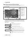
"##$ #$%&&$'
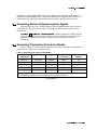
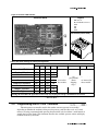
-
30022H7J
30022H8J
30015T5J
30022T5J
30015V7J
30022V6J
(
"$ Document ............. BIRHUK02
Spec Date ................ 20000831
As-of Date ............... 20000831
)#
This manual provides commissioning, programming, operating, and troubleshooting
instructions for Milnor® washer extractors equipped with the Milnor® E-P Plus® microprocessor
control. See the installation manual for information on machine installation procedures and
mechanical requirements. See the service manual for preventive maintenance, service procedures,
and mechanical parts identification. See the schematic manual for electrical parts identification
and electrical troubleshooting instructions.
*&+#%)#
The start-up display sequence for models using the E-P Plus® controller is described in the
document BICJHO01, entitled “Running a Formula.” Use the table of contents for this manual to
locate this document.
,-% --+&
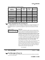
A complete identification of this manual or any document in this manual must include all
specifications shown on the front cover, as defined below:
Published manual number—Primary identification number for the manual or any variation of it.
Specified date—The approximate date of introduction of the product or product change this
manual covers.
As-of date—When a manual for an old product is generated, any new information about the old
product developed up to this date will be included in the manual.
Access date—The date the manual was generated (assembled and formatted).
Applicability—Code(s) that represent a group of machines this manual applies to and/or actual
model numbers of applicable machines. The complete list of applicable models is provided
inside the front cover.
When referring to any document used in this manual (as identified by an eight-character
document number such as BIUUUD13 at the start of the document), a complete identification of
the document must include all specifications shown on the front cover, except substituting the
document number for the published manual number.
&. #
The following, some of which may be used in this publication, are trademarks of Pellerin
Milnor Corporation:
Table 1: Trademarks
Ampsaver®
Autolint®
Auto-Purge®
Autovac
CBW®
Dye-Extractor®
Dyextractor®
E-P Plus®
Gear Guardian®
Hands-Off®
Hydro-Cushion®
Mildata®
— End of BIRHUK02 —
Milnet®
Milnor®
Miltrac
Miltron
Staph-Guard®
System 4®
System 7®
Totaltrol
Sections
Figures, Tables, and Supplements
i. About This Manual (Document BIRHUK02)
i.1.
Scope
i.2.
The Normal Display at Start-up
i.3.
How To Identify This Manual and Its Included Documents
(Document BIUUUD13)
i.4.
Trademarks of Pellerin Milnor Corporation
(Document
BIUUUD14)
Table 1: Trademarks
$
#/(&&
1.1.
Important Owner/User Information (Document BIRHUK01)
1.1.1.
Ensure Safety of All Laundry Personnel
1.1.2.
Customize Data
1.1.2.1.
When to Customize Data
1.1.2.2.
What Customizing Requires
1.1.2.3.
Data Accessibility
1.1.2.4.
If Data Becomes Corrupted
1.2.
1.3.
Determining Load Size
Table 2: Data Use and Alteration
(Document BIWUUO01)
Important Instructions for Pumped Chemical Inlets
(Document BIWUUI01)
1.3.1.
1.3.2.
1.3.3.
1.4.
1.4.1.
1.4.1.1.
1.4.1.2.
1.4.1.3.
1.4.2.
1.4.3.
How Pumped Chemical Systems Can Internally Damage Supplement 1: Preventing Dribbling by
the Washer-extractor
Purging Chemical Lines
Locating Chemical System Components to Reduce the
Figure 1: Proper Routing of Chemical
Risk of Internal Damage
Tubing
Preventing Leaks Which Can Injure Personnel and Cause Figure 2: Proper Chemical Tubing
External Damage
Connection Locations
Connecting Chemical Systems
(Document BICJFI01)
Supplement 2: Maximizing Chemical
Injection Precision
Available Chemical Injection Methods
Chemical Injection Output Signals
Optional Five-Compartment Flushing Chemical
Injector
Liquid Chemical Tube Barbed Connectors
Considerations for Pumped Chemical Systems
Connecting Devices to Receive Injection Signals
Sections
1.4.4.
Figures, Tables, and Supplements
Connecting Chemicals to 30-inch HxJ Models
Table 3: Chemical Injection Signals for
HxJ Models
#0(&&
2.1.
Controls on E-P Plus Washer-extractors
(Document
BICJHC01)
2.1.1.
2.1.2.
2.1.3.
2.2.
Figure 3: Typical Control Panel on 30015
and 30022 E-P Plus Models
Control Functions During Normal Operation
Control Functions During Manual Operation
Control Functions During Programming
Selecting an Industry Formula Set
(Document BICJHC02)
2.3.
Programming the E-P Plus Controller (Document BICJHP01)
2.3.1.
How to Avoid Data Loss
2.3.2.
Return to Run Mode (Option 0)
2.3.3.
Add or Change a Formula (Option 1)
2.3.3.1.
About the Programming Help Screens
2.3.3.2.
Moving Forward and Backward through Steps and
Decisions
2.3.3.2.1.
Actions when the Cursor is at the Step Number
2.3.3.2.2.
Actions when the Cursor is at a Decision within a
Step
2.3.3.3.
Create a New Formula
2.3.3.4.
Delete an Existing Formula
2.3.3.5.
Change an Existing Formula
2.3.3.5.1.
How to Insert or Delete a Step in an Existing
Formula
2.3.3.5.2.
The Step Decisions
2.3.3.5.3.
How to Modulate Water Valves to Regulate
Incoming Water Temperature
2.3.3.5.4.
How to Use Cooldown
2.3.3.5.5.
How to Select the Bath Level
2.3.3.5.6.
How to Select the Steam Code
2.3.3.5.7.
Injecting Chemicals
2.3.3.5.8.
How to Save or Discard Changes
2.3.4.
Configure the Control (Option 2)
2.3.4.1.
Moving Forward and Backward in Configure
2.3.4.2.
The Configure Decisions
2.3.5.
Restoring Standard E-P Plus Formulas (Document BICJUP01)
#(1#
Figure 4: Location of DIP Switches
Table 4: DIP Switch Settings for Industry
Configurations
Table 5: Codes for Inject Times of 100
Seconds and Longer
Sections
Figures, Tables, and Supplements
3.1.
Running a Formula (Document BICJHO01)
3.1.1.
Applying Power
3.1.2.
Selecting and Starting the Formula
3.1.2.1.
Load Machine and Close Door
3.1.2.2.
Selecting a Formula
3.1.3.
Unloading the Machine
3.1.4.
The Display during Automatic Operation
3.1.5.
How to Shorten, Terminate, or Suspend a Running
Formula
3.1.6.
How to Restart after Power Loss
3.1.7.
How the Flush Valve Works
3.1.8.
How Cooldown Works
3.2.
Viewing and Clearing the Formula Count Accumulator
(Document BICJUD01)
#2($
4.1.
The EP-Plus Manual Menu (Document BICJHT02)
4.1.1.
The Manual Menu
4.1.1.1.
Components
4.1.1.2.
How to Access the Manual Menu
4.1.1.3.
How to Return to the Run Mode from the Manual
Menu
4.1.2.
Determining the Software Version
4.1.3.
Viewing Microprocessor Inputs
4.1.4.
Actuating Microprocessor Outputs
4.1.5.
Testing and Verifying the DIP Switch Settings
4.1.6.
Testing Temperature and Level Sensors
4.2.
4.2.1.
4.2.2.
Error Messages (Document BICJHT01)
Error Messages at Power Up
Error Messages during Normal Operation
Table 6: E-P Plus Inputs
Table 7: E-P Plus Outputs
Figure 5: HxJ Processor Board
Table 8: Interpretation of Test DIP Switch
Display
#3()##&-&
5.1.
The E-P Plus Hardware (Document BICJUF01)
5.1.1.
Keyswitches
5.1.1.1.
Run/Program Keyswitch
5.1.1.2.
Automatic/Test Keyswitch
5.1.2.
Display
5.1.3.
Power Supply
Sections
5.1.4.
5.1.5.
5.1.6.
5.1.7.
5.1.8.
5.1.9.
CPU Processor Board
Outputs
Option Outputs
Analog to Digital Convertor
Temperature Probe
Pressure Sensor
Figures, Tables, and Supplements
#/
&&
/(/( -,4-&
Document ............. BIRHUK01
Spec Date ................ 20000831
As-of Date ............... 20000831
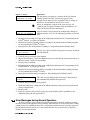
The following two procedures must be completed before this machine is placed in service:
1. Ensure the safety of all laundry personnel.
2. Customize the data contained in the memory of the machine (configuration, formulas, and
productivity/formula accumulator data).
)%"5%
Ensure that all personnel who will operate or maintain this machine read the safety manual
before permitting them to access the machine. Ensure that all user manuals are available to the
appropriate personnel and that all precautions explained in all applicable manuals are observed.
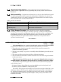
&6+
Customizing the data includes verifying that the controller is configured for the particular
application, modifying certain wash programs if necessary for optimum productivity, and
verifying that the formula count accumulator is cleared so the formula count will be accurate.
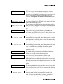
!&6+
•
•
•
•
•
When commissioning the machine
When required by error message
After replacing the microprocessor board
After upgrading the software
After adding or removing optional equipment
!&6
7—Verify configuration. Program formulas and clear
productivity data, if applicable. See the programming and operating sections in this manual for
instructions.
+"$%—Configuration and formula data can only be altered while the keyswitch
is in the Program position (data is protected by the keyswitch). Productivity data, because it is
accumulated in the Run mode, cannot be protected by the keyswitch and is accessible to anyone.
Data is accessible to the extent described in Table 2.
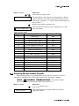
Table 2: Data Use and Alteration
Data Type
How Data can be Used and Altered
Configuration Data
Formula Data
Productivity Data
Data can be read and written over
Data can be read, written over (added to/changed) and cleared
Data can be read and cleared
-+8&#—If the microprocessor senses that data is unusable or
unreliable, an error message will appear—usually at power-up—possibly preventing machine
operation. The consequences and appropriate actions for each error message are explained in the
troubleshooting instructions. Follow these instructions exactly to ensure that corrupt data is
completely eliminated and replaced with valid data. Failure to do so may result in unsafe
operation or machine damage.
— End of BIRHUK01 —
/(0( +&5)6
Document ............ BIWUUO01
Spec Date ................ 20000831
As-of Date ............... 20000831
Putting too much linen into a properly designed laundry washer-extractor will not overload
the machine to its mechanical or electrical detriment if these guidelines are followed:
1. The goods consist of typical cotton and/or synthetic fabrics normally encountered in
commercial laundering operations.
2. The load is not so bulky as to prevent a reasonably balanced distribution prior to the onset of
extraction.
3. The extract speed has not been increased above the designed maximum.
4. The total number of intermediate and final extractions do not exceed the designed maximum
for the extract motor.
Thus, the maximum soiled linen capacity for any properly designed washer-extractor is
essentially limited by the amount of soiled goods that can actually be placed in the cylinder.
The maximum weight of soiled goods that a washer-extractor cylinder will accept depends
on the following factors:
• the internal volume of the cylinder (the space into which the goods can be placed), and
• the density (weight and bulkiness) of the specific goods
For example, many polyester-cotton fabrics have relatively low weights for their bulk so one
should rarely expect to be able to put in a published maximum capacity load of such fabrics. In
fact, published maximum capacities of machines based on the now generally accepted industry
standards will usually be achieved only with the highest density, closely woven fabrics and a
reasonable soil content.
The best load size depends on the size of the machine—plus the type of goods, soil content,
and wash quality desired. Since the latter factors vary considerably, prior experience and/or
experimentation generally yield the best results. Use these guidelines:
1. Overloading a washer-extractor will not increase production because longer wash formulas
and more rewash will be required.
2. Avoid underloads because the inevitable greater extraction imbalance will cause more extract
re-cycles and may stress the machine unnecessarily.
3. Load divided cylinder machines so that the weight in each compartment is approximately
equal at the onset of extraction. Do not put goods with grossly dissimilar water absorption
characteristics in the different compartments. Do not attempt to balance loads of wet goods in
one compartment against dry goods in the other.
— End of BIWUUO01 —
/(( -&#-&#
&-
Document ..............BIWUUI01
Spec Date ................ 20000831
As-of Date ............... 20000831
,&#&)%&-%+&
!
Many pumped liquid chemical systems dribble concentrated chemicals out of the injection
tubes when the system is not used for relatively long periods of time—as after working hours and
during weekends. This puts highly concentrated corrosive chemicals in direct contact with dry
stainless steel surfaces, and often directly on any textiles left in the machine. Chemical
deterioration (rusting) of the stainless steel and damage to the textiles is the inevitable
result.
Pellerin Milnor Corporation accepts absolutely no responsibility whatsoever for damage to
its equipment or to any textiles therein when concentrated chemicals dribble out of the
injection tubes onto any part of the machine or its contents.
Although the injection site is flushed by washer agitation on some models and after each
injection on other models to aid the injection process, this flushing provides absolutely no
protection against harmful dribble which occurs later—when the machine is no longer in use.
One foolproof solution for “dribbling” is to completely purge the appropriate chemical
injection tube with fresh water after every injection, so that only fresh water (which cannot
cause a problem) can dribble out.
Obviously, it is the sole responsibility of the pump and/or chemical supplier (not the
machine manufacturer) to furnish such a flushing device. (We understand that such flushing
type chemical injection systems—both for retrofit to existing systems and for new
installations—are now offered by others.)
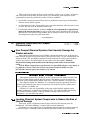
5&)%&&#
.
-+&
If the tubes, pumps, and chemical tanks are kept well below the injection point, the
likelihood of “after-hours dribbling” is reduced, but not totally eliminated.
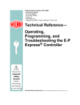
We therefore urge that tubes from any non-flushing pumped chemical system be connected
as shown in Figure 1. Although fresh-water flushing the just-used tubes after each injection
would be better, we believe routing the tubes as indicated will probably minimize the dribbling
effect about as much as possible without flushing. Never permit tanks, pumps, or any portion of
the tubes to be higher than the injection point. If loops in the injection tubes are employed, make
sure the entire loop is well below the injection point.
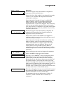
Figure 1: Proper Routing of Chemical Tubing
As shown in Figure 1, all tanks, pumps, and tubing must be lower than the injection point on the
machine and must not dribble chemicals into the machine, nor leak chemicals externally onto any portion
of the machine or its surroundings.
95.!-:
+&
All ports on the inlet are plugged at the Milnor® factory. When replacing plugs with fittings
or when reinstalling plugs, always use the sealant furnished (LocTite RTV Silicone Adhesive or
equivalent). Use properly sized hose barbs, always use clamps, and check for leaks. Use the hose
barbs furnished with your machine only if they provide the proper fit for the tubes employed.
Ensure that excessive pressures cannot build up that might burst or disconnect tubing. Instruct the
operator to monitor for leaks and report any occurences.
When calibrating injections, it is permissible to remove tubes from barbed fittings to take
samples. However, always check for leaks after installing tubes and clamps. A preferable method
is to install a three-way or two two-way valves onto each injection tube for sampling.
—Concentrated liquid
chemicals leaking from a chemical system can burn skin and eyes, cause other types of
injury or illness, and corrode machine components.
• Ensure that excessive pressures cannot build up which might burst or disconnect a
chemical delivery tube.
• Ensure that there are no external chemical leaks when the system is installed or
calibrated.
• Periodically check the system for leaks during operation.
!" # $ —Chemicals dribbling into
the machine when it is idle will corrode machine components and damage any textiles
left in the machine.
• If possible, use a system that flushes the entire chemical delivery tube after each
injection.
• If a non-flushing system is used, install tanks, pumps, and tubing below the injection
point on the machine, such that chemicals travel to the machine at an upward angle.
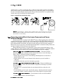
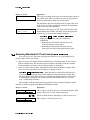
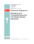
!" % $&—Certain chemicals will react when combined.
• Connect chemical inlets as shown in Figure 2.
Figure 2: Proper Chemical Tubing Connection Locations
Front View of Chemical Injection Points
Legend
1.
2.
3.
4.
5.
Soap
Softener
Bleach
Starch
Sour
"!' ( Pellerin Milnor Corporation accepts absolutely no responsibility for
damage to its equipment or to any textiles therein when concentrated chemicals
dribble out of the injection tubes onto any part of the machine or its contents.
— End of BIWUUI01 —
/(2( &)%&
Document .................BICJFI01
Spec Date ................ 20000831
As-of Date ............... 20000831
Multiple methods are available on System 7® and E-P Plus® washer-extractors to
accommodate chemical systems. Use this section to help determine the best method of chemical
injection and how to connect the chemical system. Always consult the schematic manual for this
machine before connecting chemical systems to the machine.
' ) ' *+ ,-—Contact with high voltage electricity will
kill or seriously injure you. Even with the Master Switch off and/or any Emergency
Stop switches off, three-phase power and control circuit power are still present at
several locations within electric boxes and electrical components.
' . / ,-—Improper wiring can cause the
machine to malfunction, risking injury to personnel, damage to machine components,
and damage to goods.
• Electrical and piping connections described in this section must be made only by
qualified, authorized personnel.
• Lock off and tag out power at the external disconnect switches for the washerextractor and for any chemical devices that provide power to the interpret relay box
(if furnished) before proceeding.
• Do not rely merely on the information in this section when wiring. Consult all
applicable electrical schematics.
• Do not reroute or rearrange any wires not specifically permitted by this instruction.
• Do not connect a common wire to ground. Use the common terminal furnished.
!" 0 + 1 2—Injection times of
less than 10 seconds are discouraged because fine adjustments are not possible and
factors such as pump lag time may cause significant variations in the amount of
chemical delivered.
• Size pumps or valves small enough for adequate control (i.e., for longer injection
times).
• Use two pumps or valves to inject a small or large quantity of the same chemical, if
required.
3$- / Injection of a consistent amount of chemical is important in controlling wash quality and
using chemicals economically. When chemicals are injected by units of time, as is done with
most washer-extractors, injections of short duration can be imprecise because of two reasons:
• Fine adjustments to the delivered quantity are not possible. For example, if an injection of
three seconds is extended by one second, the quantity delivered is theoretically increased
by more than 30 percent. However, if an injection of 20 seconds is increased by one
second, the theoretical quantity is increased by only five percent.
• Variations in the time between the start of the chemical signal and the start of the chemical
delivery into the machine can cause significant differences in the quantity of chemical
injected. In this case, if a pump starts more slowly some times than others, or if the
delivery tubes are partially empty at the start of the inject period, the quantity of chemical
delivered may vary significantly. As an example, assume a peristaltic pump moves
chemical along the delivery tube at a rate of three feet per second. If the delivery tube is
empty for three feet along its length, then one second of the injection time is spent injecting
air rather than chemical. If the programmed injection time is only three seconds, then one
third of the desired chemical is not being delivered. However, if the programmed injection
time is 20 seconds, the chemical delivery is only five percent less than desired.
Increasing the programmed injection time makes any variation less significant. Use
pumps and/or valves sized to allow inject times of at least 10 seconds. If injection times for
a specific chemical vary widely from one formula to another, consider using two pumps or
valves for the same chemical. Actuate one pump for injecting small quantities, and use
both pumps or valves for larger quantities.
"9$&-: &-:1#)—Five discrete signals (for chemicals 1 through 5)
are furnished standard on all washer extractors. These signals are available at a terminal strip on
System 7® and E-P Plus® machines. Check the nameplate on the machine to verify the model.
1#;9&#&;&-:—A five-compartment
dry supply injector mounted externally on the washer-extractors is offered optionally. The five
electrically operated flush valves are wired to chemical injection output signals at terminal strip
TBA.
57&$8$—A six port inlet is standard on all models.
Use these valveless inlets to connect tubes from remote chemical supply injection systems that
are not continuously pressurized and that deliver chemicals only when an injection is
commanded.
&#&)%&
Pumped chemical systems deliver chemicals to the machine intermittently usually via
peristaltic pumps. Inlets on the machine must be unrestricted at all times (valveless). The five port
pumped chemical inlets meet this requirement.
An inherent risk of this method of chemical injection is that concentrated chemicals can
dribble into the machine after it is shut down for the evening, causing machine and/or linen
damage. Because Milnor® has no control over the design or installation of pumped chemical
systems, Pellerin Milnor Corporation accepts absolutely no responsibility for damage to its
equipment or textiles therein caused in this way. Much more information on this subject is
provided in document BIWUUI01, “Important Instructions for Pumped Chemical Inlets” (see
table of contents). Consult this document before connecting a pumped chemical system.
+9
9-:)
Injection signals provide a 110VAC/50Hz or 120VAC/60Hz potential. Each signal can
accomodate one apparatus not exceeding 37 milliamperes. Inject signals cannot be made
potential-free.
!" 4 & —Board components will burn out and
require board replacement if devices driven by inject signals do not meet the electrical
specifications. Pumps generally draw a higher current and will burn out board
components.
& Acquire signals at connector TBS near the rear access panel, next to the incoming power
connections. See Table 3 for connection details.
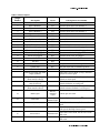
Table 3: Chemical Injection Signals for HxJ Models
Signal
Component
Chemical
Relay
Processor Board
Connection
TBS Terminal
Number
Chemical 1
Detergent
CR01M
M5-3
95
Chemical 2
Bleach
CR02M
M5-6
93
Chemical 3
Sour
CR03M
M5-5
91
Chemical 4
Softener
CR04M
M5-4
75
*Chemical 5
Starch
CR05M
M5-2
85
* Chemical 5 is not used if the machine is equipped and configured for ChemSave. In this case,
relay CR05M closes whenever the machine desires to inject a chemical.
— End of BICJFI01 —
#0
&&
0(/( 5!
Document ...............BICJHC01
Spec Date ................ 20000831
As-of Date ............... 20000831
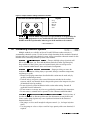
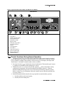
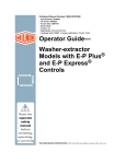
The controls on these Milnor® washer-extractors are predominantly membrane push-buttons,
some of which include indicator lights. Other controls include a keyswitch, a standard emergency
stop button, and a two-position rotary switch for main machine power. Some of these controls
serve different functions in the three operational modes of the machine. The function of each
control in the normal, manual, and programming modes of this machine is described in detail in
this document.
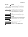
Figure 3: Typical Control Panel on 30015 and 30022 E-P Plus Models
Control Panel
Legend
1.
2.
3.
4.
5.
6.
7.
8.
9.
10.
11.
12.
13.
14.
Start button
Run/Program keyswitch
Pictorial Instructions
Run Indicator light
Master switch
Emergency Stop button
Scroll Down button
Display
Scroll Up button
Next button
Signal Cancel button
Operator Signal light
Manual Mode button
Terminate button
;+*&1#
Normal operation is the state of the machine when the machine control circuit is energized
and the Run/Program keyswitch is in the Run position. The machine may be either idle (waiting
to run a formula) or running. If the machine is idle, the message on the display will begin with
“Run Formula” and include a formula number on the second line.
1. Press the Start button () to initiate the selected wash formula. The formula begins if power
is available at the machine and the loading door is closed.
2. The Run/Program keyswitch must be in the Run position () unless the machine is being
configured or programmed. All control descriptions listed under section 2.1.1 Control
Functions During Normal Operation are based on the keyswitch being in the Run position.
Refer to section 2.1.3 for descriptions of how the controls operate with the keyswitch in the
Program position ().
3. Pictorial instructions briefly describe the steps required for normal machine operation.
1. Load the machine to the rated capacity.
2. Securely close the loading door.
4.
5.
6.
7.
8.
9.
10.
11.
12.
13.
14.
3. Select the appropriate formula for the goods in the machine.
4. Add chemicals if the machine is not connected to an automatic chemical delivery system.
5. Press the Start button.
The Run Indicator light, in the upper left corner of the Start button, indicates the type of wash
step in progress. When the machine is operating in normal mode, e.g., running a wash
formula, the on/off state of this light indicates the type of step in progress.
• Steady on indicates a fill, a drain, or a bath step.
• Brief flashes about every two to ten seconds indicate an extract step.
• Steady off indicates a drain step.
The Master switch controls power to the control circuit of the machine. Changing this switch
from the on position () to the off position () turns off the machine control circuit.
Press the Emergency Stop button to stop the machine by removing power from the machine
controls. Formulas ended in this manner can be resumed at the beginning of the interrupted
step by following the prompts on the display.
When selecting a specific formula to run, press the Scroll Down button () to display the
next lower numbered formula in memory. Press this button with the lowest formula displayed
(Formula 01) to select the highest numbered available formula (maximum of 30 formulas).
The display on these machines is a vacuum fluorescent type displaying two lines of twenty
characters each.
The Scroll Up button () functions in much the same manner as the Scroll Down button
described above. Press this button to display the next higher numbered formula in memory.
The Next button () is not used during normal operation.
Press the Signal Cancel button () to silence the operator signal buzzer which sounds when
a formula completes normally. Also, if a signal is programmed with a chemical injection in
any formula, this button must be pressed to indicate that the chemical has been added and to
resume operation.
The Operator Signal light, in the upper left corner of the Signal Cancel button (), is a
visual indicator that operator attention is required. This light is illuminated simultaneously
with the sounding of the operator signal buzzer.
The Manual button (
) has no effect while a formula is running. Pressing this button when
the display says “Run Formula xx” initiates manual mode, where the controls function as
described in section 2.1.2 Control Functions During Manual Operation.
The Terminate button () cancels all remaining steps in any running formula and initiates
the shutdown procedure for the machine. Formulas ended in this manner cannot be resumed.
;+ 1#
Manual operation is used primarily for troubleshooting the machine by activating outputs
and viewing inputs.
1. The Start button (), when pressed while the Manual button is held down, activates the
selected menu function. Depress the Start and Manual buttons simultaneously to view the
software date code. For other manual menus, release the Start button when the menu appears
on the display.
2. The Run/Program keyswitch has no effect on how the manual mode operates. However, the
status of the switch (either + or –) is displayed in field F in the Test Inputs menu.
3. The pictorial instructions apply only to normal operation, not to troubleshooting or
programming.
4. The Run Indicator light is not activated during manual operation.
5. The Master switch controls power to the control circuit of the machine. Changing this switch
from the on position () to the off position () turns off the machine control circuit.
6. The Emergency Stop button removes power from the controller in the same manner as turning
the Master switch off. If the Run/Program keyswitch is set to the Run position () when
power is restored, the controller will start in the normal operating mode with controls
functioning as described in section 2.1.1 Control Functions During Normal Operation.
7. At the manual menu, the Scroll Down button () displays the available menu items in
reverse numeric order.
8. In the manual menu, the display presents user prompts and selected information. The
software date code and machine configuration are displayed; inputs and outputs and their
respective statuses are shown in those modes. Other menu selections display DIP switch
settings, as well as temperature and level testing information.
9. The Scroll Up button () displays the next higher numbered mode in the manual menu. For
example, pressing this button once will scroll from the Software Date Code mode to the Test
Inputs mode.
10. The Next button () has no function in manual mode.
11. The Signal Cancel button () has no function in manual mode.
12. The Operator Signal light does not operate when the controller is in manual mode.
13. Use the Manual button (
) to enter manual mode when the machine is idle.
14. The Terminate button () cancels manual mode and returns the controller to the normal
operation or programming mode, depending on the setting of the Run/Program keyswitch.
Any outputs that were manually actuated while in manual mode are turned off.
;+&&
The programming mode is used to modify the actions performed in a wash formula, or to
create new wash formulas.
1. The Start button () is used in combination with the Next button () or the Terminate
button () to delete or insert a step in a wash formula, respectively.
2. The Run/Program keyswitch allows programming when set to . The Program menu
includes selections for adding and changing wash formulas, configuring the controller, and
restoring the standard formulas provided with the machine. The keyswitch must be set to the
Run position () for normal machine operation, as described in section 2.1.1 Control
Functions During Normal Operation.
3. The pictorial instructions apply only to normal operation, not to troubleshooting or
programming.
4. The Run Indicator light is not actuated during programming.
5. The Master switch controls power to the control circuit of the machine. Changing this switch
from the on position () to the off position () during programming will shut down the
machine controls. Any programming changes made in the current session will be lost.
6. The Emergency Stop button removes power from the controller in the same manner as turning
the Master switch off. If the Run/Program keyswitch is set to the Run position () when
power is restored, the controller will start in the normal operating mode with controls
functioning as described in section 2.1.1 Control Functions During Normal Operation.
7. Use the Scroll Down button () to change the selected programming parameter to the next
lower-numbered choice.
8. The display presents the programming menus and choices within those menus, including all
configuration and formula parameters.
9. The Scroll Up button () scrolls the available choices upward from the lowest available
number.
10. Use the Next button () to confirm any choice and move to the next decision in the
sequence.
11. The Signal Cancel button is not used in programming.
12. The Operator Signal light is not used in the programming mode.
13. The Manual button is not used in the programming mode.
14. The Terminate button () returns the user to the main programming menu (top line of
display reads Program X Menu) from the Add/Change Formula and the Standard Formulas
menus. The Terminate button has no effect after the Configure menu has been accessed, or
after any parameter of any formula has been accessed in the Add/Change Formula menu.
— End of BICJHC01 —
0(0( )-%;&)
Document ...............BICJHC02
Spec Date ................ 20000831
As-of Date ............... 20000831
This document applies to Milnor® HxJ, T5J, and 30015/30022VxJ model washer-extractors,
all of which use the Milnor® “188 Processor EP+” processor board. This board can be positively
identified by “P/N 08BH18EP_ ” appearing near the Milnor® logo on the processor board.
The Milnor® factory configures each E-P Plus® washer-extractor controller for the industry
specified by the purchaser when the machine is ordered. The configuration process consists of
setting the DIP switches on the processor board and installing the appropriate industry nameplate
on the machine faceplate. The DIP switch settings may be changed in the field, and new industry
nameplates may be obtained from your dealer or the Milnor® parts department.
To change industry configuration, turn the machine off and gain access to the processor
board.
' 6 ' -—Do not open the door to any electric box
without first turning the power off. These controls use 120VAC power or higher, which
is extremely dangerous.
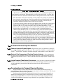
The location of the DIP switches on the microprocessor board are shown in Figure 4, as are
examples of the on and off positions. Set the switches to the desired configuration according to
Table 4. Turn the machine on; the display will show the current configuration.
Figure 4: Location of DIP Switches
Processor Board
Legend
A.
B.
1.
2.
3.
4.
DIP switch
Board identification area
OFF
ON
ON
OFF
DIP Switch (Partial View)
Table 4: DIP Switch Settings for Industry Configurations
Switch Settings
Industry Configuration
S1
S2
S3
S4
S5
S6
S7
S8
Correctional Facilities
ON
ON
ON
ON
Hotels and Motels
OFF
ON
ON
ON
Athletic Laundries
ON
OFF
ON
ON
On
Healthcare Facilities
OFF OFF
ON
ON This switch is prevents/Off
These switches
Restaurants
ON
ON
OFF
ON
not used in
allows
are not used in
these
models.
skipping
these models.
Commercial Laundries
OFF
ON
OFF
ON
steps.*
Shirt Laundries
ON
OFF OFF
ON
Offshore Laundries
OFF OFF OFF
ON
Fire-Fighter
ON
ON
ON
OFF
* Setting S6 off enables the operator to cancel any step in progress except a drain before an extract.
— End of BICJHC02 —
0(( &&5
Document ............... BICJHP01
Spec Date ................ 20000831
As-of Date ............... 20000831
The microprocessor controller used in this washer extractor operates in two modes,
depending on whether the machine is being used to process goods (the Run mode or Formula
menu) or is being programmed with operating characteristics to be used when a wash formula is
started (the Program mode). This document describes the available operator actions and display
feedback in the Program mode.
The Program mode is accessible only when the Run/Program keyswitch is set to the
Program position (), as described below. From the Program menu, there are four options
available:
•
•
•
•
Option 0: OK TURN KEY TO RUN (detailed in section 2.3.2 )
Option 1: ADD/CHANGE FORMULA (detailed in section 2.3.3 )
Option 2: CONFIGURE (detailed in section 2.3.4 )
Option 3: STANDARD FORMULAS
Each of these options is described in detail in this document. For information on how to start
the machine and run a formula, see the appropriate section listed in the table of contents of this
manual.
,"9+5
!" 7 & 8 —Never turn the Run/Program
keyswitch from the Program position to the Run position unless the display says OK
Turn Key to Run.
• Failure to follow this direction will result in the loss of all formula modifications
entered during the current programming session. Formulas not modified during this
session will not be affected.
!" & 1 —Never shut off machine
power, turn off the Master switch, or press the Emergency Stop button to exit the
Program mode.
• Once the Configure menu has been accessed, all configure decisions must be
confirmed by pressing the Next button () before another action can be taken.
• Failure to follow this direction will result in corruption of machine memory.
Use the following procedures to clear corrupted formula and configuration memory and
restore valid data.
Display or Action
Explanation
CHECKSUM ERROR
TURN KEY TO PROGRAM
LANGUAGE ?
0=ENGLISH 0
This display indicates that all memory will be cleared. The
machine controller must be reconfigured and any new
formulas or modifications to standard formulas must be reprogrammed.
Accesses the first configuration decision.
First configure decision.
<1#=
Option 0 allows for a safe return from the Program mode to the Formula menu, preserving
any changes that were made during the programming session and maintaining the integrity of
programming and configuration data.
Display or Action
PROGRAM 0 MENU
OK TURN KEY TO RUN
Explanation
This is Option 0 of the Program menu. From this display, return
to the Formula menu or select another available menu option.
Display or Action
Explanation
Returns to Run mode (Formula menu)
or
/
Scrolls the available choices in the Program menu.
";&<1#/=
Washer extractors with the Milnor® E-P Plus® control system have the capacity for up to 30
unique wash formulas. The space for these formulas is allocated in memory whether or not the
formulas are actually used.
The user interface employs similar procedures for creating a new formula and for changing
an existing formula. Both procedures are detailed below, in section 2.3.3.3 Create a New Formula
and section 2.3.3.5 Change an Existing Formula. The control system will inform the person
programming the machine whether the selected formula has already been programmed.
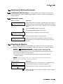
"$&&#)
Display or Action
Explanation
03 TMMQFFFHC LSCWSS*
01 0000----- -------
This is Page A of the programming menu. The cursor is at the
first decision (T=Type of Step). Each decision has an associated
help screen.
03 T TYPE OF STEP
01 0 END FORMULA
This is a typical programming help screen. Help screens appear
automatically if no valid entry is made within four seconds of
accessing the decision.
Accepts the selected value for the current decision and advances
the cursor to the next decision, regardless of the status of the
help screen.
At either Page A or B, displays formula and step name for
selected step if the help screen has not appeared.
MODIFYING
FORMULA 03 - STEP 01
This is a typical display of the formula and step name.
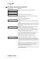
9;,8.,)#+—Each step has
two displays: Page A and Page B.
Display or Action
Explanation
03 TMMQFFFHC SCWSS*
01
This is Page A. In this example, the “03” at the left end of the
display represents the formula number. The “01” below it
represents the step number within that formula. The CWSS*
decisions shown in bold repeat for each chemical programmed in
this step.
03 SPD D E
01
This is Page B. When the cursor is advanced past the last
decision on Page A, Page B appears for the remaining decisions
in this step. The decisions required on both pages vary according
to machine model and options.
Display or Action
Explanation
/
Indexes forward/backward through the step numbers in this
formula.
Accesses the selected step and positions the cursor at decision T,
or saves all changes and exits this formula if this is the last step
of an existing formula.
Exits this formula, clearing the formula if it has not been saved,
or discarding any changes to a previously existing formula.
Display or Action
Explanation
Moves the cursor forward among Pages A and B through each
valid decision in a specific step. This accepts the standard or
default decision if another choice was not previously made.
Moves the cursor backward among the two pages, through each
valid decision within a specific step, except in the following
cases:
• If the cursor is at decision T on Page A, it will move to the
step number.
• If the cursor is at the first decision on Page B, it will back up
to the first decision (C) for the first chemical commanded in
this bath.
Displays the name of the formula and step being modified.
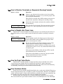
*,;&—Creating a new formula with the E-P Plus® controller entails
adding and defining steps in one of the existing but blank formulas.
Display or Action
Explanation
PROGRAM 1 MENU
ADD/CHANGE FORMULA
ADD/CHANGE FORMULA
00 RETURN TO MENU
/
ADD/CHANGE FORMULA
23 FORMULA NUMBER 23
This is Option 1 of the Program menu. From this display, either
access a formula by number to change or create, or select
another available menu option.
Accesses the formula list for selection of a formula number to
change or create.
This is the Add/Change Formula display. From this display,
either back up to the Program menu, or begin creating or
changing a formula.
Scrolls the available formula numbers. If the selected formula
number hasn't already been programmed, it is selected for add. If
the number has already been programmed, it is selected for
change, as shown in the following two displays.
Formula 23 is available for adding because it does not currently
exist.
Display or Action
Explanation
ADD/CHANGE FORMULA
07 FORMULA NUMBER 07
07 TMMQFFFHC LSCWSS*
01 205012523 200----
Accesses the selected formula for programming. Valid formula
numbers are 01 through 30.
Formula 07, Step 01 selected for programming.
+;&
Display or Action
Explanation
03 TMMQFFFHC LSCWSS*
01 0000------ ------
Formula 07 is available for changing because it already exists.
Delete an existing formula by making step 01 an End step.
Accomplish this by setting the T value for step 01 of the formula
to 0.
;&
Display or Action
Explanation
03 TMMQFFFHC LSCWSS*
01 112217513 2121250
START+NEXT/TERM TO
INS/DELETE THIS STEP
Cursor blinking on step number indicates that adding or deleting
a step is allowed.
Provides a help screen for inserting and deleting steps, as shown
below.
This is the help screen for inserting and deleting steps.
Advances the cursor without deleting or duplicating the selected
step. This key accesses the next step and allows for modification
of the values there.
Scrolls through the available choices for the decision indicated
by the cursor.
Display or Action
Explanation
+
Duplicates the selected step to the next numerical position. If
this is Step 01, the duplicated step becomes the new Step 01 and
all the following steps move to the next higher numerical
position.
Duplication of End Formula or Extract steps is prevented by the
controller.
03 TMMQFFFHC LSCWSS*
01 NEW STEP01 DUPED
This display indicates that the new step has been created as a
copy of the previous step.
Display or Action
Explanation
+
Deletes the selected step. The next step becomes the current step
by assuming the number of the step that was just deleted. All
following steps move one number lower.
Deletion of End Formula is prevented in all cases. A Bath step
can not be deleted if it falls between two Extract steps.
03 TMMQFFFHC LSCWSS*
01 STEP DELETED
This display indicates that the selected step has been deleted
from the wash formula.
—A maximum of 30 formulas may be programmed, with a maximum
combined total of 225 steps in all formulas.
Display or Action
03 TMMQFFFHC LSCWSS*
01
Explanation
This is the Type of Step decision display.
Display or Action
Explanation
0
End formula: The last step of each formula must be of type 0.
This step is automatically added as a last step if the previous step
is type 6 (final extract). A formula may be ended without a final
extract by setting the last step to type 0. If the last step before the
End Formula step is a type other than final extract, the controller
will ask “End Formula #xx?”.
Setting the first step of an existing formula to type 0 deletes the
formula, as described in section 2.3.3.4 Delete an Existing
Formula.
1
One-way wash: Washing routine for increased mechanical action
and minimum energy consumption. Use for smaller pieces where
tangling and “roping” is not a consideration.
2
Two-way wash: Washing routine for use with bedsheets and
other large items which tend to rope and tangle unless reversed.
3
Soak wash: The cylinder does not turn when this step type is
programmed. Use this step type only when no mechanical action
is required, as for especially delicate fabrics. Consider chemical
concentrations, bath time, and liquor temperature when using
this type of step.
4
Intermediate extract 1 (E1): This is the lowest extract speed for
HxJ, FxJ, and 36-inch and 42-inch VxJ models. For other
models, this is low extract speed, used for extractions between
baths or for final extract at low speed if machine has two-speed
extract.
5
This selection differs with machine model. For FxJ, HxJ, and 36inch and 42-inch VxJ models, this causes an intermediate extract
(E2). For other models, this is the final extract sequence. In final
extract the machine runs at intermediate extract speed for a
duration determined by machine model and configuration, the
runs at high extract speed for the remainder of the programmed
extract time. The formula ends when the commanded extract
time expires.
6
Final extract (E3): For certain models only, this is the sequence
leading to the highest extract speed. The machine executes an
intermediate extract 1 (E1) for a duration of 100 seconds. After
100 seconds at E1, the machine accelerates to E3 (high extract
speed) for the remainder of the programmed extract time. When
the programmed extract time ends, the cylinder stops and the
formula ends.
Display or Action
Explanation
!" # $ —For machines with software
date code 95005 or earlier, the minimum valid time for a final extract step is 1:45
(MMQ=013). Attempts to program final extract steps shorter than 1:45 may cause the
controller to continue indefinitely in high extract. Machines running software dated
95006 or later will terminate at the programmed time, but short extract times may not
allow the machine to achieve high extract speed.
• Never program a final extract step for less than 1:45 (MMQ=013) unless the machine
has software dated 95006 or later.
• If the step timer stops counting down at about 1:20 in a final extract, press to
terminate the program, then edit the formula to increase the duration of the final
extract beyond 1:45.
03 TMMQFFFHC LSCWSS*
01 1
Duration of step in minutes, minutes, and quarter minutes.
000
Invalid entry. Controller defaults this entry to 001 (15 seconds).
001
00.25 minutes; 00:15 seconds is minumum programmable time
for a bath step.
013
01.75 minutes; 01:45 seconds is the minimum valid time for an
extract step. Programming an extract step shorter than this may
cause the timer to stop counting down.
113
11.75 minutes; 11:45
633
63.75 minutes; 63:45 is the maximum programmable time for
any single step. To achieve a bath time longer than 63:45,
program two consecutive bath steps with the first ending with a
No Drain. This effectively doubles the maximum allowable bath
time.
The total time required for a formula to run to completion includes factors other than the
total of the times of each step in the formula. For these machines, add 0:40 distribution time each
time the machine enters an extract step from a bath step. Also, add 1:00 for each standard drain
(drain speed), or 1:00 for each two-way wash drain.
03 TMMQFFFHC LSCWSS*
01
xxx
FFF or CCC
---
Temperature decision appears only if the machine is supplied
with and configured for temperature control (Temp Control =
Yes), as described in section 2.3.4 .
Degrees Fahrenheit or Celsius in this bath. Units are selected in
the Configuration menu.
Display if no temperature is commanded
050°F/010°C
Minimum temperature in any bath
205°F/095°C
Maximum temperature in any bath
03 TMMQFFFHC LSCWSS*
01
x
Control of hot water valve
Display or Action
Explanation
0
Hot water valve off
1
Hot water valve on
2
Raises temperature of filling water. See section 2.3.3.5.3 for
more information.
3
invalid response—not allowed
03 TMMQFFFHC LSCWSS*
01
x
Control of cold water valve
0
Cold water valve off
1
Cold water valve on
2
invalid response—not allowed
3
Lowers temperature of filling water. See section 2.3.3.5.4 for
more information.
If a temperature is programmed in a step, the control requires either modulated water (H=2
and C=1 or 3, or C=3 and H=1 or 2) or steam injection, otherwise the cursor returns to the
temperature decision for correction. See section 2.3.3.5.3 for details on how to regulate the
temperature of incoming water.
!"# —When
programming a thermo-modulated temperature for a bath using both hot and cold water valves,
the relationship between the desired temperature and the temperature of a split fill (hot and cold
valves open simultaneously) is important.
If the desired temperature is hotter than the normal split temperature, a faster, more accurate
fill with a more constant temperature is achieved by programming the hot water valve open (H=1)
and the cold water valve to open only to lower the fill temperature (C=3).
If the desired temperature is colder than the normal split temperature, similar results can be
achieved by programming the hot water valve to open only to raise the fill temperature (H=2) and
the cold water valve to remain open constantly (C=1).
$—A cooldown is programmed as a separate bath step following the
bath in which the cooldown is desired. In the cooldown step, command a desired cooldown
temperature with all water valves programmed off (0). The E-P Plus® control automatically
inserts a no drain in the previous bath and 010 in MMQ, for a step time of 1:00.
The commanded cooldown temperature must always be at least 15 degrees Fahrenheit (8
degrees Celsius) hotter than the hottest ambient temperature or the hottest cold water temperature
that will be encountered. If this rule is not followed, achieving the desired cooler temperature
may take a long time, or even be impossible.
After the desired cooldown temperature has been achieved for 15 seconds, the cooldown
process will continue for one minute. Upon completion of the cooldown process, the machine will
drain unless a no drain was programmed to prolong the cooldown bath. Prolonging of the
cooldown bath is useful especially in cases where chemicals are to be added to the cooler bath
liquor.
Display or Action
ILLEGAL COOLDOWN
STEP. PRESS START
Explanation
This display results from commanding all water valves off (0) in
a bath following an extract step.
Display or Action
Explanation
If the machine is configured for cooldown, this keystroke returns
the cursor to the time field (MMQ).
If the machine is not configured for cooldown, but is configured
for temperature control, this keystroke returns the cursor to the
temperature field (FFF).
If temperature control is not configured, this keystroke returns
the cursor to the first water valve field.
%
&"
Display or Action
Explanation
03 TMMQFFFHC LSCWSS*
01
x
The values of high and low bath levels are determined by
machine configuration, as described in section 2.3.4.2 .
1
Low bath level
2
High bath level
Display or Action
Explanation
03 TMMQFFFHC LSCWSS*
01
x
0
Appears only if the machine is supplied with and configured for
temperature control (Temp control=yes) and steam (Steam error
greater than 0).
no steam in this bath
The six available steam codes are combinations of three yes/no decisions, as described
below.
• Early refers to whether steaming should begin at the lowest safe level, or if steaming should
only begin after the commanded level is achieved. Usually, a “Start Steaming Early” code (4,
5, or 6) is used when the machine receives only cold water or when the hot water in the plant
has a relatively low temperature. Use a No response if the machine has both hot and cold
water valves and the commanded temperature is lower than the hot water temperature.
• After refers to whether steam is allowed in this bath after temperature has been achieved once
and subsequently fallen below the commanded temperature. A No response prevents a second
steaming after temperature is first achieved. Use No if chemicals or goods may be damaged
by steam after a chemical injection (as in bleach baths).
• Timer refers to whether the timer runs or stops while steaming up to temperature. Stops
causes the timer to stop counting until the commanded temperature is first achieved. Runs is
for use when some temperature fluctuations are acceptable or when it is certain that the
commanded temperature will be nearly achieved while filling. Use Stops if temperature must
be achieved before adding chemicals, otherwise software will suppress this chemical-add
choice.
Display or Action
Explanation
1
Early=No; After=Yes; Timer=Runs. Control does not start
steaming until commanded liquor level is achieved; if necessary,
steam is allowed after temperature is first achieved; timer runs
while steaming up to temperature.
2
Early=No; After=No; Timer=Stops. Control does not start
steaming until commanded liquor level is achieved; steam is not
allowed after temperature is first achieved; timer stops while
steaming up to temperature.
3
Early=No; After=Yes; Timer=Stops. Control does not start
steaming until commanded liquor level is achieved; if necessary,
steam is allowed after temperature is first achieved; timer stops
while steaming up to temperature.
4
Early=Yes; After=Yes; Timer=Runs. Control starts steaming at
lowest safe level; if necessary, steam is allowed after
temperature is first achieved; timer runs while steaming up to
temperature.
5
Early=Yes; After=No; Timer=Stops. Control starts steaming at
lowest safe level; steam is not allowed after temperature is first
achieved; timer stops while steaming up to temperature.
6
Early=Yes; After=Yes; Timer=Stops. Control starts steaming at
lowest safe level; if necessary, steam is allowed after
temperature is first achieved; timer stops while steaming up to
temperature.
'
Display or Action
Explanation
03 TMMQFFFHC LSCWSS*
01
x
Chemicals can be added to any bath other than a cooldown bath.
A standard chemical injection can be prevented by commanding
C = 0 (no chemical in this bath) or by commanding SS = 00
(zero seconds of chemical inject time). No more than two
chemicals can be programmed per bath.
0
No chemical in this bath
2
Inject chemical number 2
5
Inject chemical number 5 (Five is maximum number of
chemicals.)
03 TMMQFFFHC LSCWSS*
01
1
Select the option determining the point in the step at which this
chemical will be injected.
Display or Action
Explanation
0
with fill. The chemical will be injected simultaneously with the
opening of the water valves.
1
at level satisfied. The chemical injection begins only after the
commanded bath level has been achieved.
2
at level and temperature satisfied. This option is only available if
a steam code of 2, 3, 5, or 6 is used (see section 2.3.3.5.6 ) to
achieve a specified temperature with Timer Stops commanded
(also described in section 2.3.3.5.6 ).
Program the duration of the chemical injection, in seconds.
03 TMMQFFFHC LSCWSS*
01
xx
00
Zero seconds, prohibits this chemical injection.
40
40 seconds. If no specific time is entered, the control
automatically inserts a value of 40. Any other value between 00
and 255 (entered as “Q5”) may be specified and will override the
40-second default duration
B9
119 seconds (example)
Q5
255 seconds (maximum duration)
Inject times longer than 99 seconds are programmed in the two-digit inject time field by
using alphabetic characters to represent values greater than 99 in the first position. The letters A
through Q are used, but not the letter O. The second position is always a number between 0 and
9. Values of the alphabetic characters are defined in Table 5 below:
Table 5: Codes for Inject Times of 100 Seconds and Longer
Alphabetic
Code
Value
Alphabetic
Code
Value
Alphabetic
Code
Value
Alphabetic
Code
Value
A
B
C
D
100
110
120
130
E
F
G
H
140
150
160
170
I
J
K
L
180
190
200
210
M
N
P
Q
220
230
240
250
!" % + 1 2—Chemical
injections should always have a duration of at least 10 seconds. With shorter injection
times, fine adjustments are not possible, and variations in response times have an
exaggerated effect on the quantity delivered.
• Select pumps or valves of the appropriate size to provide for longer injection times.
• If quantities of one chemical must vary greatly among formulas, use two pumps or
valves for that chemical.
Display or Action
03 TMMQFFFHC LSCWSS*
01
0
Explanation
Is a signal required when the chemical is desired? The signal
will not occur until the When to start chemical injection decision
is satisfied. The commanded chemical injection will not begin
until the signal is cancelled.
Display or Action
Explanation
0
No. A signal is not required with this chemical injection.
Chemicals will inject without operator intervention.
1
Yes. A signal is required with this chemical injection. The signal
will start when all programmed conditions for the chemical
(temperature and/or level) are satisfied. The actual injection will
begin only after the signal is cancelled, as below.
03 TMMQFFFHC LSCWSS*
01
3
During normal operation (formula running), this keystroke
cancels the operator signal and allows chemical injection to
begin if this decision is set to 1=Yes.
After programming the first chemical, the controller returns to
the first chemical decision to allow the programming of a second
(final) chemical.
0
No additional chemical in this bath. The cursor advances to the
next decision.
3
Chemical 3 (or any other valid chemical number). Cursor
advances to decision W for this chemical.
Select the wash speed for this step. The default value is Wash 1
for factory-supplied formulas and new bath steps.
03 SPD D E
01 x
0
Wash speed 2: High wash speed for use with goods requiring
less mechanical action. The mechanical action is reduced
because the higher speed reduces the distance the goods are
dropped.
1
Wash speed 1: Normal wash speed.
!" ( 3 31 ,-—The variable
speed inverter used in all single-motor models was programmed at the Milnor® factory
for optimum performance with your machine. The constants necessary to maintain this
performance are written inside the electrical box housing the inverter. Do not enter any
values other than those listed for inverter constants.
03 SPD D E
01
x
Select a drain type for this bath step.
Display or Action
Explanation
0
Standard drain speed—basket turns clockwise at drain
(distribution) speed.
1
Two-way wash speed—basket reverses at wash speed to provide
more mechanical action on the goods as the bath liquor is
draining away.
2
Do not drain—bath liquor is retained for later operations in this
same bath. Chemicals may be added, and temperature or level
may be raised without draining.
3
Stop with fill—the basket is kept stationary during the fill
previous to this drain, but rotates at drain speed for this drain.
4
Stop with drain—the basket is kept stationary during the drain,
allowing no mechanical action.
5
Stop with fill and drain—a combination of drain types 3 and 4,
the basket is held stationary during the previous fill and the
current drain.
03 TMMQFFFHC LSCWSS*
02 x
The cursor returns to this display to program the next step unless
the step just programmed is the last step of a formula or if the
number of steps exceeds 50, in which case the cursor advances
to decision E.
END FORMULA #03
0 NO
Appears if T=0 in previous display and this is not the last
available step in this formula.
0
No. Aborts the previous T=0 selection. Display returns to the T
(type of step) decision.
1
Yes. Accepts that the formula ends here.
Determine how this formula is to end.
03 SPD D E
02
x
0
Stopped. Operator must press to silence the signal.
1
Reversing at wash speed. Operator must press to end the
formula.
2
Drain speed. Operator must press to end the formula.
3
Tumble at wash speed. Signal sounds after two minutes.
Operator must press to end the formula.
Appears if step just previously programmed is the last step of the
formula. The controller is prepared for adding or editing another
formula, or returning to the Programming menu.
ADD/CHANGE FORMULA
00 RETURN TO MENU
PROGRAM 0 MENU
0K TURN KEY TO RUN
RUN FORMULA
00 OK TO POWER OFF
Returns to the Program menu.
This is the Program menu.
Saves changes and new formulas, then returns to the Run mode.
This is the Run Formula display.
"
—Use the procedures detailed above to navigate in a
formula and make changes. The following procedures should be used to return to the formula
menu and either save or discard the changes made.
Display or Action
Explanation
Saves all changes if the cursor is on the Step Number. This key
may need to be pressed more than one time to exit the formula.
Exits the formula and discards all changes made during this
programming session.
<1#0=
Because the microprocessor control system used in this machine is capable of controlling
several different models with a wide variety of options, each unit must be configured to match its
specific model and type of washer-extractor. This configuration informs the microprocessor of
the characteristics of this machine, such as the number of water valves, the presence of
temperature control, cooldown, etc. Such decisions are discrete to the specific machine and must
never be changed unless options are later added or removed. In addition to these hardwarespecific decisions, certain configuration choices, such as the display of English or metric units,
are left to the discretion of the owner/operator.
!" ) 1 —If the controller loses power either
accidentally or intentionally while in the Configure mode, all configuration data may be
corrupted. Reconfigure the controller at installation and any time a memory error is
detected. Although certain codes are discretionary and are so marked below, most
configure codes must match those shown on the metal configuration nameplate unless
optional equipment has been added to or removed from the machine.
9;,8.,
Display or Action
Explanation
This display indicates that the controller is in Program mode
with the Configure menu selected for access.
PROGRAM 2 MENU
CONFIGURE
LANGUAGE ?
0=ENGLISH
0
Access the Configure menu and displays the first configuration
decision.
The language option that appears here may vary according to
how the controller was last configured.
Accepts the displayed selection and automatically advances to
the next configure decision.
Accepts the displayed selection and reverts to the previous
configure decision. In certain cases earlier decisions will affect
later ones. For example, configuring for no temperature control
will automatically configure the controller for no steam, even if
temperature control is later configured.
+
Display or Action
Explanation
LANGUAGE ?
0=ENGLISH
0
/
Display of Language configuration decision. The language
chosen here controls all programming and operational prompts
on the machine display.
Scrolls the available languages, listed below.
0 = English
1 = Spanish
2 = French
3 = German
4 = Dutch
5 = Italian
6 = Portuguese
TEMP CONTROL ?
0=NO, 1=YES
1
Accepts the selected value for the current decision and advances
the cursor to the next decision, regardless of the status of the
help screen. This action is required for each configuration
decision.
Select 0=No if this machine is not equipped with steam,
cooldown, or the equipment required to provide or control these
optional functions. If 0=No is selected, the next available
decision will be Water Level Units.
Select 1=Yes if this machine is equipped with the necessary
valves and supply piping to perform steaming and/or cooldown,
as well as any necessary electronic boards to control these
options.
TEMP UNITS ?
0=°F, 1=°C
Select 0=°F to use Fahrenheit as the temperature scale.
0
Select 1=°C to use Celsius as the temperature scale.
This decision appears only if the machine is configured
for temperature control (the value for the Temp Control decision,
above, must be 1).
Display or Action
STEAM ERROR ?
0 = NO STEAM
Explanation
0
This decision appears only if the machine is configured for
temperature control (described above).
Select 0=No Steam if the machine is not equipped for steaming,
as in the case of a machine with temperature control used
exclusively for cooldown.
Select from options 1 through 3 if steam is available. The
number of minutes selected is the maximum time that the
machine will steam in an attempt to achieve the desired
temperature before a steam error is displayed. This self-clearing
error does not stop machine operation. However, for formula
steps where the timer is commanded to stop while steaming until
the desired temperature is achieved, production may be severly
restricted by steam errors.
COOLDOWN ERROR ?
0 = NO COOLDOWN
0
This decision appears only if the machine is configured, and
equipped with the mechanical and electrical hardware for
temperature control (described above).
Select 0=No Cooldown if the machine is not equipped for
cooldown, as in the case of a machine with temperature control
used exclusively for steaming.
Select from options 1 through 3 if cooldown is available. The
number of minutes selected is the maximum time that the
machine will cooldown in an attempt to achieve the desired
temperature before an error is displayed. The error is selfclearing and does not stop machine operation. However,
production may be severly restricted by cooldown errors if the
cooldown temperature is set lower than the incoming cold water
temperature.
WATER LEVEL UNITS?
0=CM 1=INCHES
1
Select 0=CM to have the water level displayed in centimeters.
OFFSET HEIGHT ?
18
This value is set at the Milnor® factory to compensate for the
height difference between bottom of the cylinder and the
location of the pressure tube connection on the drain sump.
Because the pressure tube between the pressure transducer and
the cylinder connects at an elevation not exactly equal to the
bottom of the cylinder, this value allows for an accurate display
of the water level. The unit of this value is tenths of an inch, so a
difference of 1.8 inches is entered as 18. The maximum
allowable value is 3 inches prior to software version 97004, and
4.5 inches with software versions 97004 and later.
LOW LEVEL HEIGHT ?
6
This value is the depth of the water measured from the bottom of
the cylinder shell. This level will be used for any programmed
bath step commanding a low level of bath liquor.
Select 1=INCHES to display water level in inches.
The minimum valid value for this decision is 5 inches (13
centimeters), and the maximum value is 10 inches (26
centimeters).
Display or Action
Explanation
This value is the depth of the water measured from the bottom of
the cylinder shell. This level will be used for any programmed
bath step commanding a high level of bath liquor.
HIGH LEVEL HEIGHT ?
10
The minimum valid value for this decision is equal to the value
of the Low Level Height configured just before. The maximum
value is 10 inches (26 centimeters).
MACHINE TYPE ?
0=VxJ, 1=TxJ
0
This decision only appears on T5J, V6J, and V7J models with
basket dimensions of 30015 and 30022. Select the appropriate
machine type as stated on the machine nameplate.
!" . 1—
Improper configuration will cause machines to
malfunction.
• Misconfigured VxJ models will only run at one
wash speed and one extract speed.
• Misconfigured TxJ models will run in only one
wash speed, and will not run in high extract speed.
);&
Programming mode 3 allows the owner/operator with access to a programming key to
perform either of these two actions:
1. Option 0 replaces all existing formulas with the factory default formulas for the selected
industry configuration. This selection replaces formulas 1 through 10 with the standard
industry formulas and removes all data from formulas 11 through 30.
2. Option 1 replaces only formulas 1 through 10 with the standard industry formulas. This
leaves any user-programmed data in formulas 11 through 30 intact.
!" 0 —Other than the two methods described above, it
is not possible to selectively delete field-modified or field-programmed formulas with
this programming mode. This mode erases all field-programmed formulas 1 through 10
or 1 through 30 as specified. For selective deletions and modifications, use Program
mode 1 (Add/Change Formula).
The remainder of this document details the procedure for restoring the industry standard
formulas on models employing the Milnor® E-P Plus® controller.
Display or Action
Explanation
PROGRAM 0 MENU
OK TURN KEY TO RUN
/
PROGRAM 3 MENU
STANDARD FORMULAS
This is Option 0 of the Program menu. From this display, either
return to Run mode or select another menu item.
Scrolls available choices (0 through 3) in the Program menu.
This is Option 3 of the Program menu.
Display or Action
Explanation
Accesses the Standard Formulas option of the Program menu.
CORRECTIONAL LAUNDRY
0 DEFAULT 30 FORMULA
Option 0 (Default 30 Formulas) of the Standard Formula menu
effectively deletes all 30 formulas, then replaces formulas 1
through 10 with the factory-supplied standard formulas for the
selected industry. Formulas 11 through 30 are replaced with
blank formulas.
CORRECTIONAL LAUNDRY
1 DEFAULT 10 FORMULA
Option 1 (Default 10 Formulas) deletes only formulas 1 through
10 and replaces them with the factory-supplied standard
formulas for the selected industry. Formulas 11 through 30 are
not modifed with this selection.
/
Cancels this procedure without changing or deleting any
formulas.
If the procedure is cancelled, the display returns to Option 3 of
the Program menu.
PROGRAM 3 MENU
STANDARD FORMULAS
CORRECTIONAL LAUNDRY
** PLEASE WAIT **
Defaults the selected set of formulas, either 1 through 30, or 1
through 10.
Appears for approximately five seconds as the standard formulas
are written.
Replaces the previous display when the process is completed.
PROGRAM 3 MENU
STANDARD FORMULAS
/
PROGRAM 0 MENU
OK TURN KEY TO RUN
RUN FORMULA
00 OK TO POWER OFF
Scrolls the available choices (0 Default 30 Formulas or 1
Default 10 Formulas).
Scroll to Program menu item 0 before exiting Program mode.
This is Program menu item 0. It's now safe to turn the
Run/Program keyswitch to the Run position.
Returns to Formula menu.
Formula menu; run a formula or shut down the machine.
— End of BICJHP01 —
#
1#
(/( ;&
Document .............. BICJHO01
Spec Date ................ 20000831
As-of Date ............... 20000831
"##%,
Display or Action
Explanation
The Run/Program keyswitch must be set to the Run position
before the main wall disconnect (fuse or circuit breaker) is
closed to provide power to the machine.
When power is first applied to the machine, the display shows the software copyright
information, machine name, and the checksum number. The checksum number changes with any
programming change. To detect unauthorized programming, record the checksum at the end of
each authorized programming session and compare it to the checksum displayed at each power
up.
Some Milnor® washer extractors with E-P Plus® controls do not use a speed sensing device
to verify that the basket has stopped rotating. Therefore, when power is first applied to the
machine, at least 80 seconds must elapse before any further operations can be attempted. This
provides sufficient time for the basket to coast to a complete stop if power was lost while the
machine was in a high speed extract and restored before the basket stopped.
' 4 ' ,-—The linen inside or hanging partially
outside a turning cylinder can suddenly wrap around your hand, arm, or body. The
inertia of the spinning cylinder can cause the entangled linen to twist off or sever body
parts. You can be killed or seriously injured.
• Never put any part of your body inside this machine or touch the linen while the
machine is turning.
));&
5 +—Load the machine to the rated capacity and securely
close the loading door. Review Determining Load Size (see table of contents) for guidelines on
loading machines.
);&
Display or Action
Explanation
This is the Run Formula display. From this display, the operator
can disconnect power from the machine without risking damage
to electronic parts, or he can select a formula to run, as described
below.
RUN FORMULA
00 OK TO POWER OFF
indexes forward through the 30 formulas.
indexes backward through the 30 formulas.
RUN FORMULA
07 FORMULA NUMBER 07
starts the machine with the selected formula.
indicates that the formula selected for running has not been
programmed or is not available. This display appears for three
seconds.
RUN FORMULA
DOES NOT EXIST
Example display: Formula 07 selected for running.
How a formula ends depends on the machine type, how the last step of the formula was
programmed, and whether the formula finishes without interruption or is terminated manually.
' 6 ' ,-—The linen inside or hanging partially
outside a turning cylinder can suddenly wrap around your hand, arm, or body. The
inertia of the spinning cylinder can cause the entangled linen to twist off or sever body
parts. You can be killed or seriously injured.
• Never put any part of your body inside this machine or touch the linen while the
machine is turning.
Depending on the How to End code, the controller will describe how the cycle is ending and
instruct the operator to press to escape this step in the cycle.
Display or Action
Explanation
display during the last 15 seconds of coast, or during the entire
coast time if the formula was manually terminated.
UNLOCKING THE DOOR
PLEASE WAIT
At the end of the coast time, the operator alarm sounds.
WAITING TO UNLOAD
U
Silences the operator alarm. The door unlocks, and the machine
may be unloaded.
+#%"&1#
Display or Action
Explanation
23:04 F02S01 02:37
TEMP A168/D170 LEV 1
These two displays alternate during normal operation.
23:04 STEP 01 02:37
TEMP A168/D170 SPD 0
23:04
F02S01
02:37
23:04 is the time remaining in the formula.
F02S01 indicates that the current formula is 02 (F02) and the
current step is 01 (S01).
02:37 is the time remaining in this step.
23:04
STEP01
02:37
STEP01 is the current step
EXTRACT indicates that the machine is currently executing an
extract.
TIMEHALT indicates that the timer is stopped while a chemical
is being injected. The chemical supplier must connect equipment
for this option.
TEMP A168/D170 LEV 2
Temperature in this machine is measured in degrees Fahrenheit
or Celsius, according to machine configuration.
A168 indicates that the current achieved temperature is 168
degrees. Temperature is displayed only if machine is equipped
with and configured for temperature control.
D170 indicates that the desired temperature for this step is 170
degrees. Temperature is displayed only if the machine is
equipped with and configured for temperature control.
LEV 2 indicates that the bath level achieved is Level 2.
SPD 0 indicates the bath speed (either 0 or 1) for this step.
SPD 0
LEV 2
WAIT FOR LEVEL 2 H indicates that Level 2 is programmed
for this step, but is not yet achieved. The H indicates that the hot
water valve is open; C indicates cold water, and 3 indicates extra
water.
CHEM 03 is displayed when Chemical 03 is being injected. The
number for each chemical (up to five may be connected) is
displayed as the chemical is injected. See also section 3.1.7 for
information about the chemical flush valve.
FINAL EXTRACT indicates that the step in progress is the final
step of the wash formula.
,)&)#
;&
Display or Action
Explanation
+
Cancels a step. Advances the step timer to zero for any bath, a
drain not followed by an extract, or any extract in progress. The
next step begins automatically.
This operation is possible only if DIP switch 6 on the processor
board is in the off position, allowing the cancelling of steps.
This is the Run Formula display. The door interlock, described
in section 3.1.3 , must expire before the door can be opened.
RUN FORMULA
00 OK TO POWER OFF
!
Cancels the current formula and returns the machine to the Run
Formula display.
,
,5
The E-P Plus® control remembers the formula and step it was executing if power fails or if
the wall disconnect or master switch is turned off while the machine is operating in automatic
mode.
Display or Action
Explanation
PRESS START TO RUN
STEP xx - FORMULA yy
On most machine models, this display appears when power is
restored. The formula and step which were in progress when
power was interrupted are shown.
Resumes the formula at the displayed formula and step. If the
outage occured in a bath step, level and temperature (if
commanded) must again be satisfied, even if these were already
satisfied before power was lost. Any commanded chemicals will
be injected again.
If the outage occured during a drain, that step will be repeated,
then followed by the next commanded step.
If the outage occured during an extract step, the previous bath
will be repeated before the extract step begins.
"
Terminates the formula in progress.
,;9!.
The E-P Plus® controller includes an output signal that activates the flush valve for 30
seconds after the last chemical has been injected into each bath. If a bath is shortened or
terminated before of while this valve is energized, the flush valve will be turned off. Shortening
or terminating a bath may prevent the flush valve from activating.
#
,,!.
Goods must be cool enough to handle immediately after a wash cycle is finished. However, a
drastic temperature change may set wrinkles in goods of certain fabrics. Therefore, many Milnor®
washer extractors employ a feature called cooldown to gradually lower the water temperature and
thus provide cool goods at the end of the wash cycle without setting wrinkles.
For HxJ models, the cooldown valve is turned on until high (cooldown) level is reached.
This causes the drain to open and the cooldown valve to close until high level is lost. When high
level is lost, the drain closes and the cooldown valve opens. This process continues until the
cooldown step is complete.
— End of BICJHO01 —
(0( ,;&
"&
Document .............. BICJUD01
Spec Date ................ 20000831
As-of Date ............... 20000831
The microprocessor controller increments a discrete counter for each formula near the end of
the formula. This count is maintained until the counter is cleared. The maximum number of times
a formula can be counted before resetting the accumulator is 999, after which the count will
remain at 999 until cleared. The count for each formula can only be viewed and/or cleared while
the machine is in the Run mode but not running a formula (machine is idle).
!" #7 & —The accumulated data can
be corrupted or become inaccurate if power is lost for an extended period of time, the
maximum count of 999 is reached, or the memory is corrupted by electrical
interference.
• Apply power to the machine for at least 15 seconds every 48 hours to retain the
formula count. See “Important Owner/User Information” for more detailed
information.
• To help ensure an accurate count, record the value and clear each accumulator before
it reaches 999 counts.
• If the display shows “Accumulator Error,” the count for all formulas must be cleared.
See the document on error messages for more information.
Display or Action
Explanation
This is the normal display at power-up.
RUN FORMULA
00 OK TO POWER OFF
/ Selects a formula by indexing forward/backward through the
formula numbers (01-30).
With any formula selected,
RUN FORMULA
038
05 FORMULA NUMBER 05
+
Displays the count in the upper right corner of the display.
This example shows that 38 loads were processed with formula
05 since the counter was reset.
Clears the count for the selected formula.
— End of BICJUD01 —
#2
$
2(/( Document ...............BICJHT02
Spec Date ................ 20000831
As-of Date ............... 20000831
&#—The Manual menu is made up of these selections:
1. Software Date Code—a display of the software type and date code, both of which are fixed in
the software; and the industry type, which is determined by setting the DIP switches on the
processor board.
2. Test Inputs—allows viewing of microprocessor inputs for testing when a formula is not
running. Devices, including the door latch and the level transducer, provide signals to the
microprocessor by grounding certain inputs. The status of these inputs can be monitored in
this mode, and changes to the input status will appear instantaneously.
3. Test Outputs—allows the actuation of outputs for testing when a formula is not running.
Outputs are signals from the microprocessor to other devices, such as chemical pumps and
motor contactors.
4. Test DIP Switch—displays a hexadecimal number which is unique for each possible setting
of the DIP switch. This number can be used with the appropriate tables to determine the
industry configuration of the machine, as well as whether the machine is configured to allow
the operator to skip certain steps during automatic operation.
5. Test Temp and Level—displays the pressure transducer voltage, actual level and calculated
level on the top line; and the temperature sensor signal and actual temperature on the lower
line. This menu selection is used with special testing equipment to calibrate the machine at
the factory.
,"
Display or Action
Explanation
The machine must be idle (power on, but not running a formula)
before the Manual menu can be accessed. Also, the
Run/Program keyswitch must be at the Run position ().
RUN FORMULA
00 OK TO POWER OFF
MANUAL MENU
1 SOFTWARE DATE CODE
Accesses the Manual menu.
Reverse type indicates blinking cursor position. Select one of the
Manual menu modes or return to the Run mode, as described
below.
Display or Action
Explanation
/
,
&
Display or Action
Explanation
MANUAL MENU
1 SOFTWARE DATE CODE
This is the Manual menu display.
Exits the Manual menu to the Run mode.
+&),
Display or Action
Explanation
MANUAL MENU
1 SOFTWARE DATE CODE
+
Enters the Manual menu from Run mode.
This is the Run mode display. Select a formula to run, or turn off
machine power.
RUN FORMULA
00 OK TO POWER OFF
Returns to the Run mode.
Run mode selected; control is awaiting selection of a valid
formula number. The formula number that was selected when
the Manual menu was accessed appears on the display.
RUN FORMULA
00 OK TO POWER OFF
Scrolls forward/backward through the available modes of the
Manual menu.
Accesses the Manual menu.
Manual menu accessed and Software date code mode selected.
Hold both buttons depressed to view the software date code and
machine configuration information, as shown below.
EP-PLUS/H7J 97005
RESTAURANTS LAUNDRY
Machine style (H7J), software date code (97005) and
configuration (Restaurants Laundry).
RUN FORMULA
xx FORMULA NUMBER xx
Run mode display is restored when the + button
combination is released.
, #-#
The on/off state of each input to the microprocessor can be displayed by using the Test
Inputs selection of the Manual menu. The machine must be idle (not running a formula).
Display or Action
Explanation
MANUAL MENU
2 TEST INPUTS
Accesses the Manual menu.
Manual menu accessed and Test Inputs mode selected.
Display or Action
Explanation
+
ABCDEFGHIJKLMNOP (-)
+--++----+----+- OFF
Accesses the Test Inputs mode.
The input display code on the top row corresponds to a display
code in . The status of the input is displayed beneath each code.
If the input is energized, a “+” appears. Non-energized inputs are
represented by “–”.
Restores the controller to the Run mode.
This is the Run mode display. Select a formula to run, or shut
down the machine.
RUN FORMULA
00 OK TO POWER OFF
Table 6: E-P Plus Inputs
Display Code
Input Name
Connector-Pin
A
B
C
D
E
F
G
H
I
J
K
L
M
N
O
P
Door closed
Level 1 (low level) achieved
Vibration switch tripped
Input from Inverter
Level 2 (high level) achieved
Keyswitch in Program position
Input from Ampsaver
Halt—external fault
Halt—bath time
not used
not used
not used
not used
not used
not used
not used
M6-1
M6-9
M6-2
M6-10
M6-3
M6-11
M6-4
M6-12
M6-5
M6-13
M6-6
M6-14
M6-7
M6-15
M6-8
M6-16
" #1#
Machine functions may be tested individually or in groups by using the Test Outputs
component of the Manual menu. The machine must be idle (not running a formula).
' # ' ,-—Bare manual outputs
actuate washer-extractor mechanisms. Keep all personnel clear.
Display or Action
Explanation
MANUAL MENU
3 TEST OUTPUTS
Accesses the Manual menu.
This is the Manual menu display with the Test Outputs
component selected.
Display or Action
Explanation
+
TEST OUTPUTS
01 INJECT CHEMICAL 5
/
Accesses the output testing selection.
This is the Output testing display.
Indexes forward and backward through the output names, as
shown in Table 7.
Example display with output in place to be selected and
subsequently actuated.
TEST OUTPUTS
07 COLD WATER VALVE
Accesses the selected output for actuation. All outputs are
initially disabled when accessed.
Example display with output accessed and disabled.
COLD WATER VALVE
0=OFF 1=ON
0
COLD WATER VALVE
0=OFF 1=ON
1
COLD WATER VALVE
0=OFF 1=ON
0
HOT WATER VALVE
0=OFF 1=ON
0
RUN FORMULA
00 OK TO POWER OFF
Enables the output (turns the output on).
Example display with output enabled. The cold water valve is
open.
If the output was already on, this keystroke turns it off.
Example display with output disabled. The cold water valve is
closed.
Disables (turns off) the output if it was previously enabled, and
advances to the next output.
Display after pressing to advance to the next output.
Disables the output if it was enabled, then returns to the Run
mode.
Display of Run mode.
Table 7: E-P Plus Outputs
Output
Number
1
2
3
4
5
6
7
8
9
10
11
12
13
14
15
16
17
18
19
20
21
22
Description
Device
Inject chemical 5
Inject chemical 1
Inject chemical 4
Inject chemical 3
Inject chemical 2
Hot water valve
Cold water valve
Drain solenoid
Flush valve
Cooldown (if equipped)
Extra water (if equipped)
Reuse drain (if equipped)
Steam (if equipped)
not used
not used
Door interlock
Unlock door
Wash clutch
Extract speed (use only with
empty cylinder)
Distribution (drain) speed
(Door must be closed)
Clockwise wash speed (Door
must be closed)
Counter-clockwise wash speed
(Door must be closed)
K1
K2
K3
K4
K5
K6
K7
K8
K9
K10
K11
K12
K13
K14
K15
K16
K17
K18
23
Buzz signal
24
Run light
25
Reversing wash speed
26
High extract speed
27
Fill to level 1
28
Fill to level 2
K19
K20
K21
K22
Boardmounted
signal
Boardmounted light
Consequences of Actuation
Operates inject device for chemical 5
Operates inject device for chemical 1
Operates inject device for chemical 4
Operates inject device for chemical 3
Operates inject device for chemical 2
Opens valve
Opens valve
Closes drain
Opens flush valve
Operates cooldown valve, if equipped
Operates extra water valve, if equipped
Operates reuse drain, if equipped
Operates steam valve, if equipped
Energizes door latch to locked position
Energizes door latch to unlocked position
Engages wash clutch
Locks door, releases brake (if any), and turns
cylinder at extract speed.
Locks door, releases brake (if any), and turns
cylinder at drain speed.
Locks door, releases brake (if any), and turns
cylinder clockwise at wash speed.
Locks door, releases brake (if any), and turns
cylinder counter-clockwise at wash speed.
Sounds operator alarm
Turns on light in Start button (
)
Locks door and reverses cylinder at wash
speed.
Locks door and turns cylinder clockwise at
Functional test
wash speed, then high extract speed.
Locks door, closes drain, fills to level 1 with
Functional test
cold water.
Locks door, closes drain, fills to level 2 with
Functional test
cold water.
Functional test
%+-),)
For all HxJ machines, the set of default formulas is determined by how the DIP switches on
the processor board are set. The bank of DIP switches is identified in Figure 5.
Figure 5: HxJ Processor Board
Processor Board
Legend
A.
B.
C.
D.
E.
F.
G.
H.
I.
J.
K.
Display connector
Switch panel connector
DIP switches
Temperature probe
connector
Pressure transducer for
level
Capacitor to retain
memory
Outputs to chemical
pumps
Standard outputs
Operator signal buzzer
CPU chip
Input connector
There is one unique number which identifies each possible combination of on/off settings at
the DIP switch. While the industry configuration (switch 1 through switch 4) is readily available
from the Software version mode (described in section 4.1.2 Determining the Software Version),
the settings of other switch positions are only apparent from this display or by visually inspecting
the processor board.
Display or Action
Explanation
MANUAL MENU
1 SOFTWARE DATE CODE
, Enters the Manual menu from the Run mode.
This is the first item of the Manual menu.
Scrolls down to the Test DIP Switch item.
This is the Test DIP Switch item of the Manual menu.
MANUAL MENU
4 TEST DIP SWITCH
+
Accesses the Test DIP Switch function and displays the DIP
switch setting.
This is an example of the DIP switch display. Referencing this
number in Table 8 shows that the sample machine is configured
for Restaurants Laundry, and that switch positions 5 and 6 are
enabled.
052
Terminates the Manual menu and returns controller to Run
mode.
Table 8: Interpretation of Test DIP Switch Display
!
Industry
Configuration
Standard
Display Value
Value if
Position 5 is
ON
Value if
Position 6 is
ON
Value if Both
Positions 5
and 6 are ON
Correctional
Hotel/Motel
Athletic
Healthcare
Restaurants
Commercial
Shirt Laundry
Offshore
Fire-Fighter
0
1
2
3
4
5
6
7
8
16
17
18
19
20
21
22
23
24
32
33
34
35
36
37
38
39
40
48
49
50
51
52
53
54
55
56
;)
The Test Temperature & Level selection on the Manual menu is designed primarily for use
by the Milnor® factory for testing and calibration of machines before delivery. The display is
explained briefly here, as special testing equipment is required to make adjustments from this
display.
Display or Action
R00088 A:01.0 C:01.0
R00099 A:082F [TEMP]
Explanation
The top line of the display applies to the level sensing circuit.
The “R” and the five characters immediately following it on the
top line indicate the voltage being delivered by the pressure
transducer on the processor board (see Figure 5). The “A” value
is the actual instantaneous level read by the transducer. Because
this display is only available when the drain is open, the actual
level will normally reflect no water in the machine cylinder. The
“C” value is a calculated average of the transducer levels, used
to negate the effects of rising and falling water levels caused by
the reversing wash motion. Again, in normal conditions, this
value will reflect that there is no water in the machine.
The bottom line of the display applies to the temperature sensing
circuit. Similar to the “R” value of the top line, the first six
characters of the bottom line indicate the voltage being delivered
by the temperature probe to the processor board (see Figure 5).
The “A” value on the bottom line is the temperature in degrees
Fahrenheit detected by the temperature probe.
— End of BICJHT02 —
2(0( Document ...............BICJHT01
Spec Date ................ 20000831
As-of Date ............... 20000831
,#
If an error message appears during power up, the error must be cleared before the machine
can be run or programmed.
Display or Action
Explanation
The microprocessor performs a memory check each time the
machine is turned on. This error message appears if the
microprocessor detects that the accumulator data is corrupt, in
which case all accumulators must be reset to zero.
ACCUMULATOR ERROR
TERMINATE TO CLEAR
CHECKSUM ERROR,
TURN KEY TO PROGRAM
Resets all accumulators and clears the error message. See
“Viewing and Clearing the Formula Count Accumulator” (see
Table of Contents) for more information.
Appears if there is illegal data in the configuration, formula, or
industry memory areas. Use the following procedure to clear this
error.
1. Reconfigure the machine according to the configuration information in “Programming the EP Plus® Control” (see Table of Contents).
2. Reinstall the standard (default) formulas according to the default formula loading procedure
in “Programming the E-P Plus® Control”.
3. Reprogram any lost wash formulas according to “Programming the E-P Plus® Control”.
MEMORY: FLASH
IS NOT TALKING
This message appears when the microprocessor cannot read from
the flash memory.
1. Lock off and tag out power to the machine.
2. Replace flash memory. Contact the Milnor® factory to ensure that the replacement memory is
the most current version for your machine.
3. Restore power to machine.
4. Reconfigure the machine according to the configuration information in “Programming the EP Plus® Control” (see Table of Contents).
5. Reinstall the standard (default) formulas according to the default formula loading procedure
in “Programming the E-P Plus® Control”.
6. Reprogram lost wash formulas according to “Programming the E-P Plus® Control”.
A/D BOARD IS NOT
TALKING
This error message indicates that the analog to digital board is
not communicating with the microprocessor.
1. Lock off and tag out power to the machine.
2. Check the connections at both ends of the ribbon cable between the processor board and the
analog to digital board.
3. Restore power.
4. If the error persists, lock off and tag out power to the machine. Have a qualified service
technician replace the the suspect board.
*&1#
If an error message appears on the bottom line of the display while the machine is running,
the timer shown on the top line will stop counting. When the error is corrected, the timer resumes
counting down. To troubleshoot most errors, suspend the formula in progress and turn power off.
Do not terminate the formula if it is to be resumed after the error is corrected. See "Running a
Formula" for more information.
Display or Action
DOOR NOT CLOSED
CHECK LEVEL SWITCH
LEVELS STILL MADE
TOO LONG TO FILL
TOO LONG TO STEAM
TOO LONG TO COOL
TOO LONG TO DRAIN
CHECK PROBE
EXTERNAL FAULT
INVERTER FAULT
Explanation
This error message indicates that the door input is not made
while the machine is running. Verify that the door is closed, then
check the door switch and its connection to the microprocessor.
Press if necessary to resume operation after the error is
corrected. Never operate this machine while this message is
present.
The level switch may be faulty, perhaps reporting that level 2
was achieved before level 1. Check the level switch and its input
connection to the microprocessor.
The microprocessor is still receiving information that a level is
made just before or during an extract step, or immediately before
the fill for a bath step. This error is self-clearing when level is
lost.
Time to fill to level exceeded 10 minutes. Check the water
valves, strainers, supply lines, and water pressure. The machine
will continue to fill until level is reached, at which time the error
will automatically clear and normal operation will resume.
The configured maximum time to steam up to the desired
temperature has been exceeded. Check the steam valve, strainer,
main steam header and pressure, etc. Steaming will continue
until temperature is achieved, when the error will automatically
clear and normal operation will resume.
The configured maximum time to cool down to the desired
temperature has been exceeded. Check the cooldown valve and
strainer if equipped, cold water pressure, and position of vernier
valve on cooldown inlet. Cooldown will continue until the
desired temperature is achieved, when the error will
automatically clear.
The machine did not drain properly in the allotted drain time.
This self-correcting error will clear when the water level in the
basket is low enough to begin the next operation.
This error message indicates that the resistance of the
temperature probe is outside the specified range. Test the probe
by disconnecting the probe leads from the processor board and
checking the resistance with an accurate digital ohmmeter.
Resistance between the two leads must be between 2K and 35K
Ohms. Resistance between each lead and ground must be
infinite.
The programmed chemical injection failed, usually because the
chemical supply system is empty. When chemicals are added
and can be injected, this error will clear automatically, allowing
operation to resume.
This error message appears if the microprocessor does not
receive an input from the inverter within 14 seconds of the
beginning of the formula. After 14 seconds without an inverter
input, the timer stops, the basket is stationary, and the drain
valve opens. To recover, press the Next key ().
Display or Action
VIBRATION SW TRIPPED
RECOVERY SEQUENCE
Explanation
When the vibration switch closes, the timer stops. After 80
seconds, the basket reverses at wash speed as the cylinder fills
with water. When low level is achieved, the cylinder reverses for
one additional minute at wash speed, then accelerates to extract
speed.
— End of BICJHT01 —
!
#3
)##&-&
3(/( ,
Document ............... BICJUF01
Spec Date ................ 20000831
As-of Date ............... 20000831
The Milnor® E-P Plus® microprocessor control is designed specifically for Milnor® washerextractors. Along with certain external electromechanical relay logic and sensing devices, it
controls all machine and system functions. Not every microprocessor system includes all the
following components.
>%,
4&>%,—This keyswitch allows controlling who has the necessary access
to modify wash formulas. Formulas can be modified only when this switch is turned from the Run
position () to the Program position (). To safeguard wash formulas, keep this key in a
secure place with restricted personnel access.
"&4>%,—This keyswitch allows controlling who has the necessary
access to operate the machine in Test mode for troubleshooting. Test mode can only be accessed
when this switch is turned from the Automatic position () to the Test position (). To reduce
the risk of personal injury and machine damage, keep this key in a secure place with restricted
personnel access.
+#%
Machines in the FxJ and HxJ model lines, as well as the 30015 and 30022VxJ models, use a
vacuum fluorescent display consisting of two lines of 20 characters each. This type of display is
easily identified by green characters on a black background when operating, or a nearly black
background when not operating.
,)##%
The power supply serves to provide a regulated specific voltage to the processor board and
certain auxiliary boards and devices. It converts control circuit alternating current voltage to +12
volts direct current, –12 volts direct current, and +5 volts direct current. The power supply is
switchable between 120 volts and 240 volts alternating current input voltage.
Although the +12VDC and –12VDC are not adjustable, the +5VDC is rather sensitive and
the power supply must be adjusted so the actual voltage at the processor board is between
5.04VDC and 5.06VDC as measured by an accurate digital voltmeter. If this voltage is not
within the stated range, the machine is likely to malfunction.
!
8
The central processing unit (CPU) processes data received from the various inputs, stores
information, and responds to each pushbutton entry with the appropriate action. Data is stored in
one or more of the following types of memory chips on the CPU board, depending on the
machine model.
SRAM—Static Random Access Memory stores the accumulator (formula count) data as long as
the machine has power, or via a capacitor for approximately 24 hours with power off. This
type of component is also used to retain the last formula and step in progress when power is
turned off at the machine while a formula is running. SRAM is used in all E-P Plus®
controllers.
Flash Memory—similar to EEPROM memory in function, flash memory can be electrically
erased and reprogrammed, but is faster and can retain more data than EEPROM memory.
Flash memory is used only on 188 processor boards (those used in HxJ, T5J, and 30015 and
30022VxJ models). The two flash memory chips reside in sockets IC2 and IC12. The chip in
socket IC12 contains operating instructions and the complete set of industry standard
formulas. As software updates are made available, this chip will be replaced. The chip in
socket IC2 holds the industry formulas and user changes to those formulas, as well as machine
configuration data. The chip in socket IC2 will not normally need replacing for software
updates.
1#
Depending on the processor board, output relays may be either socket-mounted to a separate
output board, or permanently soldered to the processor board. HxJ, TxJ, and 30015 and 30022VxJ
models use the 188 processor board with soldered relays.
For models other than the HxJ, TxJ, and 30015 and 30022VxJ, the 16 output relays are
socket-mounted SPDT electromechanical relays with contacts capable of faithfully conducting a
maximum of 25VA (0.1 ampere (100 millliamperes) at 220/240VAC, or 0.2 amperes (200
milliamperes) at a maximum of 110/120VAC). The output voltage will be either 220/240VAC or
110/120VAC, depending on machine model and type.
These outputs and their power source are intended only to drive another relay with higher
contact ratings that may, in turn, drive a pump, valve, solenoid, etc. from a separate power source.
Never use these outputs to directly drive a pump, valve, or solenoid unless the maximum current
required never exceeds the above values. Higher ampere or VA loads will burn out traces on the
printed circuit board or possibly overload and damage the control circuit transformer.
Machines in the HxJ, TxJ, and 30015 and 30022VxJ model lines use the 188 processor board
with output relays soldered to the processor board. These relays have the same load parameters as
those used in other models, but are SPST (single pole, single throw) rather than the SPDT (single
pole, double throw) relays used on the 788 board.
## —Although the relays on
188 processor boards are capable of handling higher loads, failure to restrict current
loads to the values stated above may cause traces on the processor board to fail, thus
destroying the board.
!
1#1#
The 188 E-P Plus® processor board used in HxJ, TxJ, and 30015 and 30022VxJ models
includes the option output relays as well as the standard output relays directly on the board. All
22 of the output relays on the 188 processor board are identical.
!
"
"+9
This component converts analog signals, such as from the temperature probe, to a digital
signal that can be used by the microprocessor. The A/D convertor is a part of the 188 processor
board used in HxJ, TxJ, and 30015 and 30022VxJ models. The A/D convertor also provides a
fixed voltage which is used as a reference for sensing temperature.
#
&#$
A thermistor temperature probe is provided in the machine sump if the machine is equiped
for optional temperature control. This probe is a resistor that changes value according to
temperature.
$
)
The 188 E-P Plus® processor board, used in all HxJ, TxJ, and 30015 and 30022VxJ models,
contains a pressure transducer unit mounted directly to the board. This transducer produces a very
small voltage that increases as the water level in the basket rises.
— End of BICJUF01 —