1
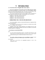
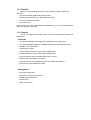
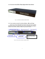
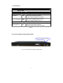
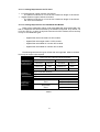
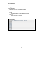
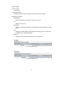
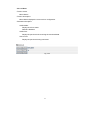
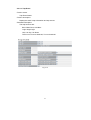
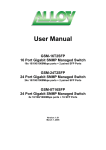
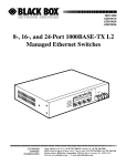
ALLOY 16-Port Gigabit Web Smart Switch GSS-16T2SFP (16x 10/100/1000Mbps ports + 2 paired SFP Ports) User’s Manual Version: 1.03 February 8, 2005 Table of Contents CAUTION ---------------------------------------------------------------------------------------------------------- III ELECTRONIC EMISSION NOTICES ----------------------------------------------------------------------------- III CHAPTER 1. INTRODUCTION ------------------------------------------------------------------------------ 2 1-1. OVERVIEW OF THE16 GIGABIT WEB SMART SWITCH ------------------------------------------------ 2 1-2. CHECKLIST ------------------------------------------------------------------------------------------------- 3 1-3. FEATURES -------------------------------------------------------------------------------------------------- 3 1-4. OVERVIEW OF THE 16 GIGABIT WEB SMART SWITCH ----------------------------------------------- 5 1-4-1. User Interfaces on the Front Panel (Button, LEDs and Plugs)------------------------- 5 1-4-2. User Interfaces on the Rear Panel------------------------------------------------------------ 6 1-5. OVERVIEW OF THE OPTIONAL SFP MODULES -------------------------------------------------------- 7 CHAPTER 2. INSTALLATION-------------------------------------------------------------------------------- 8 2-1. STARTING THE 16 GIGABIT WEB SMART SWITCH ---------------------------------------------------- 8 2-1-1. Hardware and Cable Installation -------------------------------------------------------------- 8 2-1-2. Cabling Requirements --------------------------------------------------------------------------- 9 2-1-2-1. Cabling Requirements for TP Ports -------------------------------------------------- 10 2-1-2-2. Cabling Requirements for 1000SX/LX SFP Modules ---------------------------- 10 2-1-2-3. Switch Cascading in Topology ------------------- Error! Bookmark not defined. 2-1-3. Configuring the Management Agent of 16 Gigabit Web Smart Switch -------- Error! Bookmark not defined. CHAPTER 3. OPERATION OF WEB-BASED MANAGEMENT -----------------------------------11 4-1. WEB MANAGEMENT HOME OVERVIEW --------------------------------------------------------------- 12 4-2. CONFIGURATION ----------------------------------------------------------------------------------------- 15 4-2-1. System Configuration -------------------------------------------------------------------------- 16 4-2-2. Ports Configuration ----------------------------------------------------------------------------- 18 4-2-3. VLAN Mode Configuration -------------------------------------------------------------------- 19 4-2-4. VLAN Group Configuration ------------------------------------------------------------------- 22 4-2-5. PVID Configuration ----------------------------------------------------------------------------- 25 4-2-6. Aggregation Configuration -------------------------------------------------------------------- 27 4-2-7. Mirror Configuration ---------------------------------------------------------------------------- 28 4-2-8. Quality of Service Configuration------------------------------------------------------------- 29 4-2-9. Bandwidth Management----------------------------------------------------------------------- 36 4-2-10. Trap Event Configuration -------------------------------------------------------------------- 38 4-2-11. Max. Packet Length --------------------------------------------------------------------------- 39 4-3. MONITORING --------------------------------------------------------------------------------------------- 40 4-3-1. Statistics Overview------------------------------------------------------------------------------ 40 4-3-2. Detailed Statistics ------------------------------------------------------------------------------- 41 4-4. MAINTENANCE ------------------------------------------------------------------------------------------- 44 4-4-1. Status ---------------------------------------------------------------------------------------------- 44 4-4-1-1.Switch Status ------------------------------------------------------------------------------- 45 4-4-1-2. TP / Fiber Ports Status------------------------------------------------------------------- 47 4-4-1-3. Aggregation -------------------------------------------------------------------------------- 48 4-4-1-4. VLAN----------------------------------------------------------------------------------------- 49 4-4-1-5. Mirror----------------------------------------------------------------------------------------- 51 4-4-1-6. Trap Event ---------------------------------------------------------------------------------- 52 4-4-1-7. Maximum Packet Length---------------------------------------------------------------- 53 4-4-2. Warm Restart ------------------------------------------------------------------------------------ 54 4-4-3. Factory Default ---------------------------------------------------------------------------------- 55 4-4-4. Logout --------------------------------------------------------------------------------------------- 56 CHAPTER 4. MAINTENANCE ----------------------------------------------------------------------------- 57 5-1. RESOLVING NO LINK CONDITION --------------------------------------------------------------------- 57 5-2. Q&A----------------------------------------------------------------ERROR! BOOKMARK NOT DEFINED. APPENDIX A TECHNICAL SPECIFICATIONS -------------------------------------------------------- 58 APPENDIX B MIB SPECIFICATIONS ------------------- ERROR! BOOKMARK NOT DEFINED. ii Caution Electronic Circuit devices are sensitive to static electricity. Dry weather conditions or walking across a carpeted floor may cause you to acquire a static electrical charge. To protect your switch, always: • Touch the metal chassis of your computer to ground the static electrical charge before you handle the switch. • Pick up the switch by holding it on the left and right edges only. Electronic Emission Notices Federal Communications Commission (FCC) Statement This equipment has been tested and found to comply with the limits for a class A computing device pursuant to Subpart J of part 15 of FCC Rules, which are designed to provide reasonable protection against such interference when operated in a commercial environment. European Community (CE) Electromagnetic Compatibility Directive This equipment has been tested and found to comply with the protection requirements of European Emission Standard EN55022/EN60555-2 and the Generic European Immunity Standard EN50082-1. EMC: EN55022(1988)/CISPR-22(1985) EN60555-2(1995) EN60555-3 IEC1000-4-2(1995) IEC1000-4-3(1995) IEC1000-4-4(1995) class A class A 4K V CD, 8KV, AD 3V/m 1KV – (power line), 0.5KV – (signal line) Australian C-Tick Compliance. This equipment is compliant with the required Australian C-Tick standards. iii About this user’s manual This user’s manual will guide you on how to install, configure and monitor the 16 port Gigabit Web Smart Switch through the built-in web management interface. Overview of this user’s manual Chapter 1 “Introduction” describes the features of the 16 Gigabit Web Smart Switch Chapter 2 “Installation” Chapter 3 “Operation of the Web-based Management” Chapter 4 “Maintenance” 1. Introduction 1-1. Overview of the 16 Gigabit Web Smart Switch The 16-port Gigabit Web Smart Switch meets all IEEE 802.3/u/x/z Gigabit, Fast Ethernet specifications. The switch includes 14x 10/100/1000Mbps Copper Ports, and 2 paired Gigabit Copper/SFP Ports. The switch can be managed through its Ethernet port using a Web-based browser such as Internet Explorer. Port 15 and 16 supports dual media. SFP mini-GBIC for Fiber connections (LC single mode and multimode) and copper 10/100/1000Mbps with auto-detection. 1000Mbps LC, Multi-Mode, SFP Fiber transceiver 1000Mbps LC, 10km, SFP Fiber transceiver 1000Mbps LC, 30km, SFP Fiber transceiver 1000Mbps LC, 50km, SFP Fiber transceiver 1000Mbps WDM-SC, 20km, 1550nm SFP Fiber WDM transceiver 1000Mbps WDM-SC, 20km, 1310nm SFP Fiber WDM transceiver The 10/100/1000Mbps copper port meets all IEEE 802.3/u/x/z Gigabit and Fast Ethernet specifications. The 1000Mbps SFP Fiber ports via SFP modules are compliant with all IEEE 802.3z and 1000Base-SX/LX standards. 1000Mbps Single Fiber WDM transceivers are designed with an optic Wavelength Division Multiplexing (WDM) technology that transports bi-directional full duplex signal over a single fiber. • Key Features in the GSS-16T2SFP QoS: The switch offers powerful QoS functions. This feature adds support of TOS fields within the IP header (equal DSCP low 3 bits) on Layer 3 of the network framework and 6 types of network transmission events on Layer 4. VLAN: The switch supports Port-based VLAN and IEEE802.1Q Tagged VLAN. With support for 16 active VLANs having a VLAN ID from 1 to 4094. Port Trunking: Allows one or more links to be aggregated together to form a Link Aggregation Group. 2 1-2. Checklist Before you start installing the switch, verify that the package contains the following: The GSS-16T2SFP Gigabit Web Smart Switch Mounting Accessories (for 19” Rack Shelf mounting) This User's Manual CD-ROM AC Power Cord Please notify your sales representative immediately if any of the aforementioned items are missing or damaged. 1-3. Features The 16 port Gigabit Web Smart Switch, provides comprehensive features as listed below. • Hardware • 14x 10/100/1000Mbps Auto-negotiation Gigabit Ethernet copper ports • 2x 10/100/1000Mbps copper or 1000Mbps SFP Fiber dual media auto sense. • 400KB on-chip frame buffer • Jumbo frame support • Programmable classifier for QoS (Layer 4/Multimedia) • 8K MAC address and 4K VLAN support (IEEE802.1Q) • Per-port shaping, policing, and Broadcast Storm Control • IEEE802.1Q-in-Q nested VLAN support • Full-duplex flow control (IEEE802.3x) and half-duplex backpressure • Extensive front-panel diagnostic LEDs • Management • Easy port configuration • Port traffic monitoring and counters • Simple system Information • Port mirroring • Static trunk function 3 • 802.1Q VLAN • Maximal packet length up to 9216 bytes for jumbo frame applications • Broadcasting Suppression to avoid network problems • Trap event sending • Firmware Defaults and Customised Firmware saving and restoring • Supports hot plug/unplug SFP modules • Quality of Service (QoS) for real time applications based on information from Layer 2 to Layer 4. • Built-in web-based management 4 1-4. Overview of the GSS-16T2sfp Gigabit Web Smart Switch Fig. 1-1 Full View of the GSS-16T2SFP Switch 1-4-1. User Interfaces on the Front Panel (Button, LEDs and Plugs) There are 16 copper Gigabit Ethernet ports and 2 SFP fiber ports for optional removable modules on the front panel of the switch. LED display area, locating on the left side of the panel, contains a Power LED, which indicates the power status of the switch, and 16 LED’s indicate the status of the ports on the switch. TP Port Status Indication LEDs Power Indication LED Gigabit Ethernet Port Fiber Port Status Indication LEDs RESET Button: RESET button is used to restore the system default settings. Fig. 1-2 Front View of the GSS-16T2SFP Switch 5 SFP Fiber Port • LED Indicators LED POWER Color System LED Green Function Lit when +5V DC power is on and good 10/100/1000Ethernet coppers Port 1 to 16 LED On when connection with remote device is good LINK/ACT Green Blinks when any traffic is present Off when cable connection is not good Green when 1000Mbps speed is active Green/ Amber when 100Mbps speed is active 10/100/1000Mbps Amber Off when 10Mbps speed is active 1000SX/LX Gigabit Fiber Port 15, 16 LED On when connection with the remote device is good SFP(LINK/ACT) Green Blinks when any traffic is present Off when module connection is not good Table1-1 1-4-2. User Interfaces on the Rear Panel AC Line 100-240V 50/60 Hz Fig. 1-3 Rear View of the GSS-16T2SFP Switch 6 1-5. Overview of the Optional SFP Modules With the GSS16T2SFP switch, copper ports 15 and 16 are paired with the SFP Fiber ports (LC); these ports support 10/100/1000Mbps on the copper interface or 1000Mbps Fiber via the SFP interfaces. 1000Mbps SFP Fiber transceiver can be used for high-speed uplink connections to fiber backbones or servers. A range of optional SFP types are listed below: 1000Mbps LC, MM, SFP Fiber transceiver (MGBIC-MLC) 1000Mbps LC, SM 10km, SFP Fiber transceiver (MGBIC-SLC10) 1000Mbps LC, SM 40km, SFP Fiber transceiver (MGBIC-SLC40) 1000Mbps LC, SM 50km, SFP Fiber transceiver (MGBIC-SLC50) 1000Mbps LC, SM 80km, SFP Fiber transceiver (MGBIC-SLC80) 1000Mbps LC, SM 120km, SFP Fiber transceiver (MGBIC-SLC120) Fig. 1-4 Front View of 1000Base-SX/LX LC, SFP Fiber Transceiver Fig. 1-5 Front View of 1000Base-LX WDM SC SFP Fiber Transceiver WDWDMM 7 2. Installation 2-1. Starting the GSS16T2SFP Gigabit Web Smart Switch This section provides a quick start guide for: - Hardware and Cable Installation - Management Station Installation - Software booting and configuration 2-1-1. Hardware and Cable Installation Please Note: ⇒ Wear a grounding strap device to avoid damaging the switch with electrostatic discharge. ⇒ Be sure that the power switch is in the ‘OFF’ position, before you insert the power cord. • Installing any optional SFP Fiber Transceivers to the GSS16T2SFP Gigabit Web Smart Switch. Fig. 2-1 Installation of Optional SFP Fiber Transceiver • Connecting the SFP Module to the Chassis: The optional SFP modules are hot swappable, so you can plug or unplug them while the power is applied to the switch. 1. Verify that the SFP module is of the correct type to suit the switch 2. Slide the module along the slot and ensure that the module is properly seated against the slot socket/connector. 3. Install the media cable for network connection 4. Repeat the above steps, as needed, for each module to be installed into the switch 8 • Copper Ports Cable Installation ⇒ The switch copper ports support MDI/MDI-X auto-crossover. This enables use of either straight-through or crossover Cat 5E cables. ⇒ Use Cat. 5 grade RJ-45 copper cables to connect to the copper RJ-45 ports. ⇒ Repeat the above steps, as needed, for each RJ-45 port to be connected. • Power On The switch supports 100-240 VAC, 50-60 Hz power supply. The power supply will automatically convert the local AC power source to DC power. When initial power is applied, all the LED indicators will light up for a brief period while the system performs its startup tests. Once the initial tests (‘POST test’) have completed all except the power LED should return to an off state. • Firmware Loading After power on, the boot-loader will load the switch firmware into the main operational memory. This process will take about 30 seconds. Once completed, the switch will flash all the LED’s once switch to a ready state. 2-1-2. Cabling Requirements To help ensure a successful installation and keep network performance at its optimum level, please take care in using correct Cat5E or greater cabling. Please ensure that Stranded core runs for no more than 10 meters, and that solid core runs for a maximum of 100meters. Poor cabling is the most common cause for network dropouts, or poor performance. 9 2-1-2-1. Cabling Requirements for TP Ports ⇒ For Fast Ethernet copper network connections The Cable must be Cat. 5 or Cat. 5e with a maximum length of 100 meters. ⇒ Gigabit Ethernet copper network connection The Cable must be Cat. 5 or Cat. 5e with a maximum length of 100 meters. Cat. 5e is recommended. 2-1-2-2. Cabling Requirements for 1000SX/LX SFP Module There are two categories of fiber, multi mode (MM) and single mode (SM). The later is categorized into several classes by the distance it supports. They are SX, LX, LHX, XD, and ZX. In terms of physical connectors for SFP modules, there currently is only LC and WDM SC types Gigabit Fiber with multi-mode LC SFP module Gigabit Fiber with single-mode LC SFP module Gigabit Fiber with WDM SC 1310nm SFP module Gigabit Fiber with WDM SC 1550nm SFP module The following table lists the types of fiber that are supported. Others not listed here may be support upon request. Multi-mode Fiber Cable and Modal Bandwidth IEEE 802.3z Gigabit Ethernet 1000SX 850nm Multi-mode 62.5/125µm Modal Bandwidth Distance Multi-mode 50/125µm Modal Bandwidth Distance 160MHz-Km 220m 400MHz-Km 500m 200MHz-Km 275m 500MHz-Km 550m Single-mode Fiber 9/125µm 1000BaseLX/LHX/XD/ZX Single-mode transceiver 1310nm 10Km, 40Km Single-mode transceiver 1550nm 50Km, 80Km 1000Base-LX Single Fiber (WDM SC) Single-Mode *20Km Single-Mode *20Km Table2-1 10 TX(Transmit) 1310nm RX(Receive) 1550nm TX(Transmit) 1550nm RX(Receive) 1310nm 4. Operation of Web-based Management This chapter instructs you how to configure and manage the GSS16T2SFP Gigabit Web Smart Switch through the web user interface. The default values of the GSS16T2SFP Gigabit Web Smart Switch are listed in the table below: IP Address 192.168.1.1 Subnet Mask 255.255.255.0 Default Gateway 192.168.1.254 Password admin Table 4-1 Browse the switch via its IP address http://192.168.1.1 The following screen (see Fig.4-1) should display and ask for a system password in order to login. The default password is “admin”. Note: the management interface can only be used by one administrator any one time. For best display results, we recommend you use Microsoft IE and have the resolution at 1024x768. 11 Fig. 4-1 4-1. Web Management Home Overview After you have successfully logged into the switch the system status information is displayed as in Fig. 4-2. This page informs you about the basic information of the system, including “Switch Status”, “TP Port Status”, “Fiber Port Status”, “Aggregation”, “VLAN”, “Mirror”, “Trap Event”, and “Maximum Packet Length”. From this information, you can ascertain the software version used, MAC address, port status and so on. For more details, please refer to Section 4-4-1. 12 Fig. 4-2 13 • The Basic Page Layout. The switch graphic at the top section of the windows, displays the current status of both Copper TP and Fibre SFP ports. The left side of the main window, provides the gateway to the sub menu options. These submenus are grouped into 3 parts, Configuration Monitoring Maintenance The functions of each group are described in the corresponded sections through the remainder of this manual. The following list is the main function tree. Root Configuration Monitoring Maintenance 14 4-2. Configuration 11 functions are including in the System Configuration group. Each of them will be described in detail in the following sections. Configuration System Configuration Ports Configuration VLAN Mode Configuration VLAN Group Configuration PVID Configuration Aggregation Configuration Mirror Configuration QoS Configuration Bandwidth Management Trap Event Configuration Max. Packet Length 15 4-2-1. System Configuration System configuration is one of the most important options in the switch. Without proper configuration, the network manager will not be able to manage or access the switch. The switch supports manual IP address settings. When the IP address is changed, you must reboot the switch to have the settings take effect. Changing the IP address will require you to change you management IP in your web browser. Fig. 4-3 Function name: System Configuration Function description: Set IP address, subnet mask, default gateway, system name, password and auto logout timer for the switch. Parameter description: MAC Address (RO) : The Ethernet MAC address of the management agent in this switch. Firmware Version (RO): The firmware version of this switch. Hardware Version (RO): The hardware version of this switch. Serial Number (RO): The serial number is assigned by the manufacturer. 16 IP Address (RW): Configure the IP settings. Then, click <Apply> button to update. Default: 192.168.1.1 Subnet Mask (RW): Configure the Subnet Mask setting. Then, click <Apply> button to update. Default: 255.255.255.0 Default Gateway (RW): The Default Gateway is used in Routed networks to determine the net hop for all non local destinations. Default: 192.168.1.254 System Name (RW): Set a special name for this switch. Up to 16 characters are allowed in this parameter. Any alphanumeric characters and null are acceptable. Default: GSS-16T2SFP Password (RW): Set a password for this switch. Up to 16 characters are allowed in this parameter. Any alphanumeric character is acceptable. Default: admin Auto Logout Timer (RW): Set the auto-logout timer. Valid values are 0 ~ 60 minutes. 0 Value means the auto-logout timer is disabled. Default: 0 17 4-2-2. Ports Configuration Function name: Port Configuration Function description: Port Configuration allows changing of the various port settings. Parameter description: Mode: Set the speed and duplex of the port. - If the media is 1Gbps fiber, then there are three modes to choose from: Auto Speed, 1000 Full and Disable. - If the media is TP (copper), then there are additional Speed/Duplex settings. Speed modes = 10,100 or 1000Mbps, and duplex modes = full duplex or half duplex. The following table summarizes the functions that each media type supports. Media type 1000M TP 1000M Fiber NWay ON/OFF ON/OFF Speed 10/100/1000M 1000M Duplex Full for all, Half for 10/100 Full In Auto Speed mode, there is no default values. In Forced mode, default values depend on your settings. Flow Control: Select from either Enable or Disable for Flow Control. If flow control is set to Enabled, then both parties can send PAUSE frames to the transmitting device(s) if the receiving port is too busy to handle the data rate being sent to it. When it is set to Disabled, then there will be no flow control on the port. In congested situations the switch will drop packets. Default State : Enable Fig. 4-4 18 4-2-3. VLAN Mode Configuration The switch supports Port-based VLAN and Tag-based VLAN (802.1q). 16 active VLANs can be support with VLAN ID’s from 1~4094. VLAN configuration is used to partition your LAN into small broadcast domains (groups). Properly configuring VLANS can improve your network security and increase network performance by limiting broadcast propagation. Function name: VLAN Mode Setting Function description: There are 4 VLAN Modes: Port-based, Tag- based, Metro mode or Disabled. These are selected from the drop down list. Selecting one will take affect immediately. Parameter description: VLAN Mode: Disable: Disable all VLAN functions. This is the default setting. Port-based: Port-based VLAN simply groups ports together. Ports within the same group can talk to each other ports not in the same group are blocked from communicating. Any port can be a member of more than one VLAN to enable shared server, internet or uplink ports. This switch can support up to a maximal of 16 port-based VLAN groups. Tag-based: Tag-based VLAN identifies its members by a VID that is included in the headers of packets sent and received. This is quite different from portbased VLAN, in that Tagged VLANs can exist as groups across multiple switches in your enterprise where as port VLANS are local only to the switch that they are defined on. Port ingress (incoming) and egress (outgoing) rules allow for filtering of packets that don’t conform to your specific policies on accepting or denying non Tagged packets. Each tag-based VLAN that is configured must be assigned a VLAN name and a VLAN ID. Valid VLAN ID’s are from 1 to 4094. Administrators can create a total of up to 16 Tag VLAN groups. 19 Metro Mode: Metro Mode is a quick configuration VLAN option designed for Metro WAN deployment. It uses Port-based VLAN and creates 14 or 15 Portbased VLAN groups. Fig. 4-5 20 Up-link Port: This feature is only enabled when the metro mode is selected. Option 15: All ports are assigned a unique VLAN with Port 15. Port 15 ends up a member of 15 VLAN groups, one VLAN for each port. This secures intra port traffic, but allows all ports access to a single uplink port(15). Each VLAN has 2 members. 15 VLANS in total. Option 16: All ports are assigned a unique VLAN with Port 16. Port 16 ends up a member of 15 VLAN groups, one VLAN for each port. This secures intra port traffic, but allows all ports access to a single uplink port (16). Each VLAN has 2 members. 15 VLANS in total. Option 15&16: All ports are assigned a unique VLAN with Port 15 and 16. Both ports 15 and 16 end up members of 14 VLAN groups, one VLAN for each port. This secures intra port traffic, but allows all ports access to both uplink ports (15 and 16). Each VLAN has 2 members. 14 VLANS in total. Fig. 4-6 21 4-2-4. VLAN Group Configuration Function name: VLAN Group Configuration Function description: In port-based VLAN mode, this will display the ID – Description - and Members of existing port-based VLAN groups. If in tag-based VLAN mode, this will display the ID - Description – VID and Members of the existing tag-based VLAN group. The switch can only be configured to support either port-based VLAN or tag-based VLAN. When selecting one of the VLAN modes, the switch will display the appropriate configuration data as required. You can easily create and delete VLAN groups by using the <Add Group> and <Delete Group> function buttons, or click the Group ID directly to edit it. Parameter description: ID (Group ID): When you want to edit a VLAN group, you must select the Group ID field. Then enter your Tag Based VLAN Group Settings or Port Based VLAN Group Settings depending on your VLAN mode selection. Description: The description defined by administrator is associated with a VLAN group. VID: VLAN identifier. Each tag-based VLAN group has a unique VID. It appears only in tag-based mode. Member: This is used to add or delete ports as members of this VLAN. Use the check box (;) beside the port x to enable it. 22 Fig. 4-7 Add Group: Create a new port-based VLAN or tag-based VLAN, depending on the VLAN mode selected. Fig. 4-8 23 Delete Group: Select the check box (;) beside the ID, to delete a group. Then press the <Delete Group> button to delete the group. Fig. 4-9 24 4-2-5. PVID Configuration Function name: PVID Configuration Function description: From within this menu users can assign a VID number for each port. The range of VID numbers is from 1 to 4094. You can also choose ingress filtering rules to each port. There are two ingress filtering rules which can be applied to the switch. Ingress Filtering Rule 1 is “forward only packets with VID matching this port’s configured VID”. Ingress Filtering Rule 2 is “drop untagged frame”. Parameter description: Port 1-16: Port number. PVID: The PVID range will be from 1-4094. Before you set a PVID number, ensure that you have created a Tag-based VLAN with VID of the same number. For example, if port 1 receives an untagged packet, the switch will apply the PVID (assume VID 5) to tag this packet, the packet then will be forwarded as a packet tagged with VID 5. Rule 1: Forward only packets with VID matching this port’s configured VID. You can apply Rule 1 as a way to a given port to filter unwanted traffic. In Rule 1, a given port checks if the received packet is a member of the VLAN which the received port has been assign via its PVID. For example, if port 1 receives a tagged packet with VID=100 (VLAN name=VLAN100), and if Rule 1 is enabled, the switch will check if port 1 is a member of VLAN100. If it is, then the received packet is forwarded; otherwise, the received packet is dropped. Rule 2: Drop untagged frame. You can configure a given port to accept all frames (Tagged and Untagged) or just receive tagged only frames. If the former is the case, then packets either tagged or untagged will be processed. If the later is the case, only packets carrying a VLAN tag will be processed, all other packets will be discarded. Note: If Rule 1 is enabled and port 1, for example, receives an untagged packet, the switch will apply the PVID of port 1 to tag this packet, the packet then will be forwarded. Tag: This is an egress rule applied on data transmitted out of the port. Select untag or tag. Tag means that the outgoing packets must carry VLAN tag headers, select the check box (;). Untag means that the outgoing packets carry no VLAN tag headers. 25 Untag State: If this is enabled and the Untag VID matches the VID of the packet, then the tag would be removed. If enabled without a match, no operation will occur. If disabled, no operation will occur. Untag VID: Valid range is 0~4094. Fig. 4-10 26 4-2-6. Aggregation Configuration The Aggregation (Port Trunking) Configuration is used to configure Link Aggregation. You can bundle more than one port with the same speed, full duplex and the same MAC to be a single logical port, thus the logical port aggregates the bandwidth of these ports. This allows you to create a higher speed uplink or backbone connection via bandwidth aggregation. For example, if there are three Fast Ethernet ports aggregated in a logical port, then this logical port has bandwidth three times as high as a single Fast Ethernet port has. Function name: Aggregation Configuration Function description: Display the current setup of Aggregation/Trunking. With this function you can add a new trunk group or modify the members of an existing trunk group. Parameter description: Normal: Define ports that will not participate in any aggregation/trunking group. Group 1~8: Group the ports that you need to aggregate/trunk. Up to 8 ports can be selected for each group. Fig. 4-11 27 4-2-7. Mirror Configuration Function name: Mirror Configuration Function description: Mirror Configuration is used to monitor the traffic on the network. For example, assume that Port A is a Sniffer Port and Port B is the Source Port, this allows the traffic passed by Port B to be copied to Port A for monitoring purposes. Parameter description: Sniffer Mode: Used for the activation or de-activation of the Port Mirror function. Default is disable. Sniffer Port: Set up the port that will perform the monitoring. Valid port is Port 1~16 and default is Port 1. Source Port: Set up the port that will be monitored. Select the check box (;) under the port label. Valid port range is Port 1~16. Fig. 4-12 28 4-2-8. Quality of Service Configuration The switch offers powerful QoS functions including: VLAN tagged priority for 8 levels, TOS field IP header (equal DSCP low 3 bits) on Layer 3 network framework, 6 types of layer 4 network transmission events, and IP DiffServe QoS services. In the Quality of Service (QoS) Configuration there is an option named ”Default Class”. Once you have selected one of the four QoS methods, this Default Class is used to group packets that do not match any of the QoS rules defined for the particular QoS method selected. For instance, if you set the QoS function as VLAN Tag Priority mode, and then choose Default Class as High, the priority of the packets with no tags will be considered as High priority precedence. The initial value of the Default Class is High. Fig. 4-13 Function name: VLAN Tag Priority Function description: VLAN tags have 3 bits that belonging to a priority flag. These 3 bits can define 8 traffic classifications. These classifications can then be mapped to High priority or Low priority queues. Packets tagged as High priority will be forwarded over packets with a low priority when the destination port is in a congested state. 29 Fig. 4-14 Parameter description: Quality of Service (QoS) Vlan Tag Configuration: Used for setting up QoS based on Vlan tags. Port: Select the port which your bit mapping will apply. Optionally you can select to control all ports at the same time from the “All” selection. Bit 0, Bit 1, Bit 2: Control the Tag priority and offer 8 levels of QoS. Class: The 8 levels of QoS are then mapped to High or Low Priorities for each ports output queue respectively. 30 Function name: IP ToS Classification Function description: Within the Layer 3 network framework is a TOS field for IP headers. The GS16T2SFP can prioritize packet forwarding based on this TOS header. TOS Headers include 3 bits for 8 levels of TOS. Once again these 8 levels can be mapped to High or Low priority queues. Fig. 4-15 Parameter description: Quality of Service (QoS) ToS Configuration: Used for setting up the TOS QoS based on Layer 3 IP headers. Port: Select the port which your bit mapping will apply. Optionally you can select to control all ports at the same time from the “All” selection. Bit 0, Bit 1, Bit 2: Control the TOS priority and offer 8 levels of QoS. Class: The 8 levels of TOS are then mapped to High or Low Priorities for each ports output queue respectively. 31 Function name: IP TCP/UDP Port Classification Function description: In L4 QoS Configuration you can prioritize packets based on the application type that they contain. ie. Down prioritize web browsing, e-mail and FTP. Parameter description: Disable IP TCP/UDP Port Classification: Disables all L4 application based QoS. Down prioritize web browsing, e-mail, FTP and news: Enable Low prioritization for standard Internet Applications Prioritize IP Telephony (VoIP): Enable High prioritization for VoIP applications Prioritize iSCSI: Enable High prioritization for iSCSI applications Prioritize web browsing, e-mail, FTP transfers and news: Enable High prioritization for standard Internet Applications. Prioritize Streaming Audio/Video: Enable High prioritization for standard Video and Audio Streaming Applications Prioritize Databases (Oracle, IBM DB2, SQL, Microsoft): Enable High prioritization for Database Applications 32 Advanced Mode: The Advanced Mode allows you to further customize the initial simple configuration defaults with your own TCP/UDP port definitions. Or create your own definition list from scratch. Refer Fig 4-16. Special TCP/UDP class: Select the custom TCP/UDP port definitions as High or Low priority. Default class (all other TCP/UDP ports): Select all other TCP/UDP ports as a default priority class of High or Low. Port: Select the port which your Special TDP/UDP class will apply. Optionally you can select to control all ports at the same time from the “All” selection. Special UDP/TCP Port Selection: The following are port numbers defined by the six specific default TCP/UDP L4 rules: Down prioritize web browsing, e-mail, FTP and news: port number 80,280,443,25,110,20,21,69,119,2009 Prioritize IP Telephony (VoIP):1718,1719,1720 Prioritize iSCSI:3225,3260,3420 Prioritize web browsing, e-mail, FTP transfers and news: 80,280,443,25,110,20,21,69,119,2009 Prioritize Streaming Audio/Video: 2979,1755,7070,7071,554,8000 Prioritize Databases (Oracle, IBM DB2, SQL, Microsoft):66,1571,1575,523,118,156,3306,1232,1433,1434 33 Fig. 4-16 Advanced Mode Fig. 4-17 Simple Mode Simple Mode: Toggle the <Simple> / <Advanced> button to switch between modes and to display details on the TCP/UDP ports configured (See Fig 4-17). 34 Function name: IP Diffserv Classification Function description: IP Diffserve Classification supports up-to 64 (0~63) Traffic Classifications based on a 6-bit field in the DSCP header of IP packets. The GSS-16T2SFP switch allows mapping of these 64 classifications to High or Low priority queues. Parameter description: IP Differentiated Services (DiffServ) Configuration: Used for setting up the IP Differentiated Services Configuration QoS. Diffserv: Display 64 (0~63) DiffServ Priority items. Class: The 64 traffic types can be mapped to High Priority or Low Priority queues. Fig. 4-18 35 4-2-9. Bandwidth Management Function name: Bandwidth Management Function description: The Bandwidth Management function is used to set Ingress and Egress bandwidth limits for each port. Fig. 4-19 Parameter description: Port Number: Select the port which you want to add a Rate control policy to. Optionally you can select to control all ports at the same time from the “All” selection. All Traffic for Ingress Rate Limiting: Define the rate for incoming traffic on the selected port. Incoming traffic will be discarded if the rate exceeds the value you set up in Data Rate field. Pause frames are also generated if flow control is enabled. The limited format of the packet includes unicast, broadcast and multicast. Valid range is 0~1000. Broadcast & Multicast for Ingress Rate Limiting: Define the rate for incoming Broadcast and Multicast traffic on the selected port. Incoming traffic will be discarded if the rate exceeds the value you set up in Data Rate field. The limited format of the packet only includes broadcast and multicast. Valid range is 0~1000. 36 All Traffic for Egress Rate Limiting: Define the rate for outgoing traffic on the selected port. Packet transmission will be delayed if the rate exceeds the value you set up in Data Rate field. Traffic may be lost if egress buffers are congested. The limited format of the packet includes unicast, broadcast and multicast. Valid range is 0~1000. 37 4-2-10. Trap Event Configuration Function name: Trap Event Configuration Function description: The Trap Event Configuration enables the GSS-16T2SFP switch to send out the trap information when pre-defined events occur. The switch offers 7 different trap events and 2 configurable trap host. Trap messages are enabled by selecting the tick (;) box beside each event description. Most events support a counter function to help identify the number of times that the event has occurred. (not inc. Warm Boot and Cold Boot events) Parameter description: The Trap functions are listed below. Boot: Warm Boot, Cold Boot Login: Illegal Login Link: Link Up, Link Down Tx/Rx error: Rx error threshold, Tx error threshold Fig. 4-20 38 4-2-11. Max. Packet Length Function name: Max. Packet Length Function description: The switch is capable of dealing with 9k Jumbo Frames. Jumbo frames are effective in point to point environments for large payload data transfers. They maximize the data to header payload ratio, so that more data is sent with less header information. (note the transmitting and receiving nodes need to support Jumbo Frames) Parameter description: Max. Frame Size for Jumbo Frame(bytes): Set up the maximum packet length that each port can accept. Maximum length can be 1518 bytes, 1532 bytes or 9216 bytes. The default is 1518 bytes. Fig. 4-21 39 4-3. Monitoring There are two functions contained in the monitoring section of the management. Monitoring Statistics Overview Detailed Statistics 4-3-1. Statistics Overview The Statistics Overview function collects summary information about port based traffic counters. This can includes Frames, Bytes, and Errors. In the Fig. 4-22, all ports are displayed in a summary format. If any counter overflows its maximum level, then it will reset and resume from 0 (zero). Function name: Statistics Overview Function description: Display a summary of each port’s traffic, including Tx Bytes, Tx Frames, Rx Bytes, Rx Frames, Tx Errors and Rx Errors. Parameters description: Tx Bytes: Total transmitted bytes. Tx Frames: Number of the packet transmitted. Rx Bytes: Total received bytes. Rx Frames: Number of the packet received. Tx Errors: Number of bad packets transmitted. Rx Errors: Number of bad packets received. 40 Fig. 4-22 4-3-2. Detailed Statistics Function name: Detailed Statistics Function description: Displays detailed counters for a specific port. Fig. 4-23 Parameter description: Rx Packets: Number of the packet received. RX Octets: Total received bytes. Rx High Priority Packets: Number of Rx packets classified as high priority. Rx Low Priority Packets: Number of Rx packets classified as low priority. Rx Broadcast: Number of the received broadcast packets. Rx Multicast: Number of the received multicast packets. Tx Packets: Number of the packets transmitted. 41 TX Octets: Total transmitted bytes. Tx High Priority Packets: Number of Tx packets classified as high priority. Tx Low Priority Packets: Number of Tx packets classified as low priority. Tx Broadcast: Number of the transmitted broadcast packets. Tx Multicast: Number of the transmitted multicast packets. Rx 64 Bytes: Number of 64-byte frames (includes non valid packets) received. Rx 65-127 Bytes: Number of 65 ~ 126-byte frames (includes non valid packets) received. Rx 128-255 Bytes: Number of 127 ~ 255-byte frames (includes non valid packets) received. Rx 256-511 Bytes: Number of 256 ~ 511-byte frames (includes non valid packets) received. Rx 512-1023 Bytes: Number of 512 ~ 1023-byte frames (includes non valid packets) received. Rx 1024-Bytes: Number of 1024-max_length-byte frames (includes non valid packets) received. Tx 64 Bytes: Number of 64-byte frames (includes non valid packets) transmitted. Tx 65-127 Bytes: Number of 65 ~ 126-byte frames (includes non valid packets) transmitted. Tx 128-255 Bytes: Number of 127 ~ 255-byte frames (includes non valid packets) transmitted. Tx 256-511 Bytes: Number of 256 ~ 511-byte frames (includes non valid packets) transmitted. Tx 512-1023 Bytes: Number of 512 ~ 1023-byte frames (includes non valid packets) transmitted. 42 Tx 1024-Bytes: Number of 1024-max_length-byte frames (includes non valid packets) transmitted. Rx CRC/Alignment: Number of Alignment errors and CRC error packets received. Rx Undersize: Number of short frames (<64 Bytes) with valid CRC. Rx Oversize: Number of long frames(according to max_length register) with valid CRC. Rx Fragments: Number of short frames (< 64 bytes) with invalid CRC. Rx Jabber: Number of long frames(according tomax_length register) with invalid CRC. Rx Drops: Frames dropped due to the lack of receiving buffer. Tx Collisions: Number of collisions experienced during transmission. Tx Drops: Number of frames dropped due to excessive collision, late collision, or frame aging. Tx FIFO Drops: Number of frames dropped due to the lack of transmitting buffer. Fig. 4-23 43 4-4. Maintenance There are four functions contained in the maintenance section. Maintenance Status Warm Restart Factory Default Logout 4-4-1. Status 8 sections are reported on in the switch status screen TP Port Status, Fiber Port Status, Aggregation, VLAN, Mirror, Trap Event and Maximum Packet Length Status Switch Status TP Port Status Fiber Port Status Aggregation VLAN Mirror Trap Event Maximum Packet Length 44 4-4-1-1.Switch Status Fig. 4-24 Function name: Switch Status Function Description: Display the status information of this switch. Parameter Description: Product Name: Display the product name of the switch Firmware Version: Display the firmware version of the switch. Hardware Version: Display the hardware version of the switch. Serial Number: The serial number is assigned by the manufacturer. IP Address: Display the IP address of the switch. Subnet Mask: Display the subnet mask of the switch. Default Gateway: Display the default gateway of the switch. 45 MAC Address: Display the Ethernet MAC address of the switch. System Name: Display the model of the switch. Auto Logout Timer: Display the setting of auto-logout timer in the web UI. 46 4-4-1-2. TP / Fiber Ports Status Function name: TP/Fiber Ports Status Function description: TP/Fiber Port Status, displays a summary of the port status Fig. 4-25 Parameter description: Port: Port 1 – 16. Both port 15 and 16 are optional SFP modules. Link Status: Displays link as active or down. Speed: Displays the speed and duplex of all ports. Options are: <Copper> 10Mbps, 100Mbps and 1000Mbps Half duplex and Full duplex. <Fiber SFP> 1000Mbps supported only. Flow Control: Display port flow control status. There are two types of flow control in Ethernet, Backpressure for halfduplex operation and Pause flow control (IEEE802.3x) for full-duplex operation. The switch supports both methods. Default: Enabled 47 4-4-1-3. Aggregation Function name: Aggregation Status Function description: Display the current setup of Aggregation/Trunking. Parameter description: Normal: Ports not participating in any aggregation/trunking groups. Group 1~8: Display the members of the Group. Fig. 4-26 48 4-4-1-4. VLAN Function name: VLAN Status Function description: Display the status the switch VLAN mode and VLAN group settings. Parameter description: VLAN Mode: Display Port-based, Tag-based or metro mode VLAN. ID: Display the Group ID. Description: Display the description defined by administrator associated with the VLAN group. VID: Display the VLAN identifier. Each tag-based VLAN group has a unique VID. It appears only in tag-based modes. Member: Display the port members belonging to each VLAN Group. Fig. 4-27 Tag-based VLAN Fig. 4-28 Port-based VLAN 49 Fig. 4-29 Metro mode VLAN 50 4-4-1-5. Mirror Function name: Mirror Status Function description: Mirror Status displays the current mirror configuration. Parameter description: Sniffer Mode: Display the mirror status Default is disabled. Sniffer Port: Display the port that is the receiving the monitored data. Source Port: Display the port that is being monitored. Fig. 4-30 51 4-4-1-6. Trap Event Function name: Trap Event Status Function description: Display the switch’s trap information and trap events. Parameter description: The trap functions are: Boot: Warm Boot, Cold Boot Login: Illegal Login Link: Link Up, Link Down Tx/Rx error: Rx error threshold, Tx error threshold Fig. 4-31 52 4-4-1-7. Maximum Packet Length Function name: Max. Packet Length Status Function description: Display the per port setting for maximum packet length. Parameter description: Max. Frame Size: Display the per port setting for maximum packet length. Options are: 1518 bytes, 1532 bytes or 9216 bytes. Fig. 4-32 53 4-4-2. Warm Restart The Web management interface offers a Warm Restart option. This simply reboots the switch with the current switch settings intact. (optionally you could also press the RESET button on the front panel to reset the switch the switch). Function name: Warm Restart Function description: Reboot the switch. This will take around thirty (30) seconds to complete the system boot. Fig. 4-33 54 4-4-3. Factory Default Function name: Factory Default Function description: Factory Default function will reset the default setting and replace the current working configuration. Fig. 4-34 55 4-4-4. Logout The GSS-16T2SFP support an auto logout from the web interface, but there is also a manual logout function. If you need to release control of the web management so that another user can access it immediately, then you can manually perform a Logout with this function. The switch is then immediately available to other users. Function name: Logout Function description: Logout from the web interface. Fig. 4-35 56 5. Maintenance 5-1. Resolving No Link Condition The possible causes for a not receiving link are: z The attached device is not powered on z The cable may not be the correct type or is faulty z The installed building premise cable is faulty (internal wall/ceiling cabling) z The port may be faulty. 57 Appendix A Technical Specifications Features • • • • • • • • • • • • • • • • • 14 (10/100/1000Mbps) Gigabit Ethernet (TP) switching ports compliant with IEEE802.3, 802.3u, 802.3z and 802.3ab. 2 Gigabit Copper/SFP paired ports for support of Fiber or Copper media. Non-blocking store-and-forward shared-memory Web-Smart switched. Supports auto-negotiation for configuring speed and duplex mode. Supports 802.3x flow control for full-duplex ports. Supports collision-based and carrier-based backpressure for half-duplex ports. All ports can be configured for disabled mode, forced mode or auto-polling. Supports Head of Line (HOL) blocking prevention. Supports broadcast storm filtering. Web-based management provides the ability to completely manage the switch from any web browser. Supports Port-based VLAN and Protocol-based (IEEE802.1Q) VLAN. Auto-aging with programmable inter-age time. Supports 802.1p Class of Service with 2-level priority queuing. Supports port trunking with flexible load distribution and failover Supports port sniffer function Programmable maximum Ethernet frame length from 1518 to 9216 bytes. Efficient self-learning and address recognition mechanism enables forwarding rate at wire speed. 58 Hardware Specifications Standard Compliance: IEEE802.3/802.3ab / 802.3z / 802.3u / 802.3x Network Interface: Configuration 10/100/1000Mbps Gigabit copper 1000Base-SX Gigabit Fiber 1000Base-LX Gigabit Fiber Mode Connector NWay TP (RJ-45) 1000 FDX *SFP 1000 FDX *SFP 1000 FDX *SFP 1000Base-LX Single Fiber WDM Port 1 - 16 15,16(Option) 15,16(Option) 15,16(Option) *Port 15, 16 are Copper/SFP fiber dual media ports with auto detected feature *Optional SFP module supports LC or WDM SC transceiver Transmission Mode: 10/100Mbps supports full or half duplex 1000Mbps supports full duplex only Transmission Speed: 10/100/1000Mbps for Copper 1000Mbps for Fiber (SFP) Full Forwarding/Filtering Packet Rate: PPS (packets per second) Forwarding Rate 1,488,000PPS 148,800PPS 14,880PPS Speed 1000Mbps 100Mbps 10Mbps MAC Address and Self-learning: 8K MAC address 4K VLAN table entries, Buffer Memory: Embedded 400 KB frame buffer Flow Control: IEEE802.3x compliant for full duplex Backpressure flow control for half duplex Cable and Maximum Length: TP 1000Base-SX 1000Base-LX 1000Base-LX WDM Cat. 5 UTP cable, up to 100m Up to 220/275/500/550m, Depending on Multi-Mode Fiber type Single-Mode Fiber, various distances 10/30/50Km etc… Single-Mode Single Fiber, up to 20Km 59 Diagnostic LED: System LED : Per Port LED: 10/100/1000M TP Port 1 to 16 1000M SFP Fiber Port 15,16 Power Requirement : Power : LINK/ACT, 10/100/1000Mbps : SFP(LINK/ACT) AC Line Voltage : 100∼240 V Frequency : 50∼60 Hz Consumption : 30W Ambient Temperature : 0° to 50°C : 5% to 90% Humidity Dimensions : 44(H) × 442(W) × 209(D) mm Comply with FCC Part 15 Class A & CE Mark Approval, C-Tick 60