1
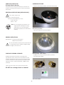
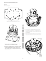
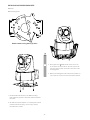
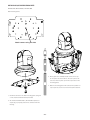
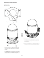
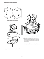
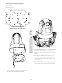
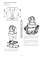
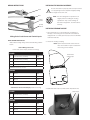
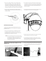
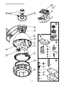
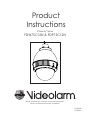
Product
Instructions
IP Ready™ Series
FDW75C12N & FDP75C12N
Before attempting to connect or operate this product,
please read these instructions completely.
81-IN5329
04/28/06
-1-
IMPORTANT SAFEGUARDS
1. Read Instructions - All the safety and operating instructions should be read
before the unit is operated.
2. Retain Instructions -The safety and operating instructions should be retained
for future reference.
3. Heed Warnings - All warnings on the unit and in the operating instructions
should be adhered to.
4. Follow Instructions - All operating & user instructions should be followed.
5. Electrical Connections - Only a qualified electrician should make electrical
connections.
6. Attachments - Do not use attachments not recommended by the product
manufacturer as they may cause hazards.
7. Cable Runs - All cable runs must be within permissible distance.
8. Mounting - This unit must be properly and securely mounted to a supporting
structure capable of sustaining the weight of the unit. Accordingly:
a. Installation should be made by a qualified installer.
b. Installation should be in compliance with local codes.
c. Care should be exercised to select suitable hardware to install the unit,
taking into account both the composition of the mounting surface and
the weight of the unit. Be sure to periodically examine the unit and the
supporting structure to make sure that the integrity of the installation
is intact. Failure to comply with the foregoing could result in the unit
separating from the support structure and falling,with resultant damages
or injury to anyone or anything struck by the falling unit.
UNPACKING
Unpack carefully. Electronic components can be damaged if improperly handled
or dropped. If an item appears to have been damaged in shipment, replace it
properly in its carton and notify the shipper. Be sure to save:
1. The shipping carton and packaging material. They are the safest material in
which to make future shipments of the equipment.
2. These Installation and Operating Instructions.
SAFETY PRECAUTIONS
!
CAUTION
RISK OF
ELECTRIC SHOCK!
CAUTION: TO REDUCE THE RISK OF
ELECTRICAL SHOCK, DO NOT EXPOSE
COMPONENTS TO WATER OR MOISTURE.
The lightning flash with an arrowhead symbol, within an
equilateral triangle, is intended to alert the user to the
presence of non-insulated "dangerous voltage" within the
product's enclosure that may be of sufficient magnitude
to constitute a risk of electric shock to persons.
!
The exclamation point within an equilateral triangle is
intendedtoalerttheusertopresenceofimportantoperating
and maintenance (servicing) instructions in the literature
accompanying the appliance.
SERVICE
If the unit ever needs repair service, customer should contact Videolarm
(1-800-554-1124) for return authorization & shipping instructions.
TECHNICAL SUPPORT
Videolarm has set-up a 24 hour technical support line for their customers.
24 HOUR TECHNICAL SUPPORT
1-800-554-1124
LIMITED WARRANTY FOR VIDEOLARM INC. PRODUCTS
VIDEOLARM INC. warrants this Product to be free from defects in material or workmanship, as follows:
PRODUCT CATEGORY
PARTS
LABOR
All Enclosures and Electronics
Three (3) Years
Three (3) Years
Pan/Tilts
Three (3) Years **6 months if used in autoscan
Three (3) Years **6 months if used in autoscan
Poles/PoleEvators
Three (3) Years
Three (3) Years
Warrior/Q-View/I.R. Illuminators
Five (5) Years
Five (5) Years
Controllers
Three (3) Years
Three (3) Years
Power Supplies
Three (3) Years
Three (3) Years
Accessory Brackets
Three (3) Years
Three (3) Years
During the labor warranty period, to repair the Product, Purchaser will either return the defective product, freight prepaid, or deliver it to Videolarm Inc. Decatur GA.
The Product to be repaired is to be returned in either its original carton or a similar package affording an equal degree of protection with a RMA # (Return Materials
Authorization number) displayed on the outer box or packing slip. To obtain a RMA# you must contact our Technical Support Team at 800.554.1124, extension 101.
Videolarm will return the repaired Product freight prepaid to Purchaser.Videolarm is not obligated to provide Purchaser with a substitute unit during the warranty
period or at any time. After the applicable warranty period, Purchaser must pay all labor and/or parts charges.
The limited warranty stated in these product instructions is subject to all of the following terms and conditions:
1. NOTIFICATION OF CLAIMS: WARRANTY SERVICE: If Purchaser believes that the Product is defective in material or workmanship, then written notice
with an explanation of the claim shall be given promptly by Purchaser to Videolarm but all claims for warranty service must be made within the warranty period.
If after investigation Videolarm determines that the reported problem was not covered by the warranty, Purchaser shall pay Videolarm for the cost of investigating
the problem at its then prevailing per incident billable rate. No repair or replacement of any Product or part thereof shall extend the warranty period as to the entire
Product.The specific warranty on the repaired part only shall be in effect for a period of ninety (90) days following the repair or replacement of that part or the
remaining period of the Product parts warranty, whichever is greater.
2. EXCLUSIVE REMEDY: ACCEPTANCE: Purchaser’s exclusive remedy and Videolarm’s sole obligation is to supply (or pay for) all labor necessary to repair
any Product found to be defective within the warranty period and to supply, at no extra charge, new or rebuilt replacements for defective parts.
3. EXCEPTIONS TO LIMITED WARRANTY: Videolarm shall have no liability or obligation to Purchaser with respect to any Product requiring service during
the warranty period which is subjected to any of the following: abuse, improper use: negligence, accident, lightning damage or other acts of God (i.e., hurricanes,
earthquakes), modification, failure of the end-user to follow the directions outlined in the product instructions, failure of the end-user to follow the maintenance
procedures recommended by the International Security Industry Organization, written in product instructions, or recommended in the service manual for the Product.
Furthermore,Videolarm shall have no liability where a schedule is specified for regular replacement or maintenance or cleaning of certain parts (based on usage)
and the end-user has failed to follow such schedule; attempted repair by non-qualified personnel; operation of the Product outside of the published environmental
and electrical parameters, or if such Product’s original identification (trademark, serial number) markings have been defaced, altered, or removed. Videolarm
excludes from warranty coverage Products sold AS IS and/or WITH ALL FAULTS and excludes used Products which have not been sold by Videolarm to the Purchaser.
All software and accompanying documentation furnished with, or as part of the Product is furnished “AS IS” (i.e., without any warranty of any kind), except where
expressly provided otherwise in any documentation or license agreement furnished with the Product.
4. PROOF OF PURCHASE: The Purchaser’s dated bill of sale must be retained as evidence of the date of purchase and to establish warranty eligibility.
DISCLAIMER OF WARRANTY EXCEPT FOR THE FOREGOING WARRANTIES,VIDEOLARM HEREBY DISCLAIMS AND EXCLUDES ALL OTHER WARRANTIES, EXPRESS OR IMPLIED,
INCLUDING, BUT NOT LIMITED TO ANY AND/OR ALL IMPLIED WARRANTIES OF MERCHANTABILITY, FITNESS FOR A PARTICULAR PURPOSE AND/OR ANY WARRANTY WITH REGARD TO ANY CLAIM
OF INFRINGEMENT THAT MAY BE PROVIDED IN SECTION 2-312(3) OF THE UNIFORM COMMERCIAL CODE AND/OR IN ANY OTHER COMPARABLE STATE STATUTE.VIDEOLARM HEREBY DISCLAIMS
ANY REPRESENTATIONS OR WARRANTY THAT THE PRODUCT IS COMPATIBLE WITH ANY COMBINATION OF NON-VIDEOLARM PRODUCTS OR NON-VIDEOLARM RECOMMENDED PRODUCTS
PURCHASER CHOOSES TO CONNECT TO PRODUCT.
LIMITATION OF LIABILITY THE LIABILITY OF VIDEOLARM, IF ANY, AND PURCHASER’S SOLE AND EXCLUSIVE REMEDY FOR DAMAGES FOR ANY CLAIM OF ANY KIND WHATSOEVER,
REGARDLESS OF THE LEGAL THEORY AND WHETHER ARISING IN TORT OR CONTRACT, SHALL NOT BE GREATER THAN THE ACTUAL PURCHASE PRICE OF THE PRODUCT WITH RESPECT TO WHICH
SUCH CLAIM IS MADE. IN NO EVENT SHALL VIDEOLARM BE LIABLE TO PURCHASER FOR ANY SPECIAL, INDIRECT, INCIDENTAL, OR CONSEQUENTIAL DAMAGES OF ANY KIND INCLUDING, BUT NOT
LIMITED TO, COMPENSATION, REIMBURSEMENT OR DAMAGES ON ACCOUNT OF THE LOSS OF PRESENT OR PROSPECTIVE PROFITS OR FOR ANY OTHER REASON WHATSOEVER.
FDW75C12N, FDP75C12N
IP Ready Network Housing
ASSEMBLING THE UNIT:
Remove content from all boxes. Contents should include:
IP Ready Network Housing with 12Vdc input, wall mount or
pendant mounting, heater & blowers, ready for standard IP
PTZ cameras.
ELECTRICAL SPECIFICATIONS (OUTDOOR ONLY):
!
Power 12Vdc, Class 2 Only
Total Power: 21 watts Housing only
Accessories (Heater/Blower): 21 watts
Heater: 20 watts
Blower: 1 watt
NOTE: This unit is designed for operation in an
upright position. Installing the housing
upside down may cause damage to
the internal equipment, and will void the
warranty.
Main Housing Assembly
Either with wall mount or pendant bracket
GENERAL INSTRUCTIONS:
Tools Required: .100" Flat Head Screwdriver
Phillips Head Screwdriver
!
Be sure the bracket is properly and securely mounted
to a supporting structure capable of rigidly holding
the weight of the entire unit.
CARE AND CLEANING OF DOMES:
Dome Assembly - Clear or Tinted
Do notUHPRYHWKHSURWHFWLYHÀOPXQWLOWKHSURGXFWLV
assembled and installed.
All FDW75 and FDP75 units include an optically clear
polycarbonate dome. The dome is an optical device and
VKRXOGEHKDQGOHGZLWKH[WUHPHFDUH/HDYHSURWHFWLYHÀOP
on dome until product is fully assembled and installed. Even
though the dome is virtually unbreakable, it can be easily
scratched.
Clean only with a clean cotton cloth and warm water.
DO NOT use a strong solvent or cleanser!
3 Packet Assemblies
-3-
INSTALLATION OF PTZ CAMERA
instruction for the model that matches the unit you have.
INDEX OF CAMERAS
AXIS 213
5
AXIS 214
6
AXIS 215
CANON VB-C10R
7
8
CANON VB-C50iR
9
CANON VC-C4R / VC-C50iR
10
ELMO PTC-200C
11
ELMO PTC-201
12
ELMO PTC-400C
13
ELMO PTC-401
14
JVC VN-C30U
15
PANASONIC BB-HCM381 / KX-HMC280
16
PIXORD 261 / 262
17
SONY SNCRZ30
18
SONY SNCRZ50
19
TOSHIBA IK-WB21A
20
-4-
INSTALLING QUICK RELEASE BRACKETS
AXIS 213
2539 Mounting Plate:
Attach camera using these (2) holes
½"
3. Place (3) 8 x 32 x 9Phillips head screws on the top
of the spacer as shown above. Be sure to place the
1"
screws so that they line up with the open slots on the
mounting plate.
4. Slide the mounting plate with camera into position on
top of spacers. Secure 3 screws and captive fastener.
Captive Screw
2"
1. Install the camera to the 2539 mounting plate using
(2) 10-32 screws and lockwashers provided.
2. The Axis 213 camera requires 3.5" of spacing for optimal
position within the housing. Use (4) 2" spacer(s), plus
(4) 1" spacer(s) and (4) ½" spacer(s) provided in the (2)
hardware packets.
(3) screws
in housing
-5-
INSTALLING QUICK RELEASE BRACKETS
AXIS 214
2685 Mounting Plate:
Attach camera using these (3) holes
2"
3. Place (3) 8 x 32 x
Phillips head screws on the top
of the spacer as shown above. Be sure to place the
screws so that they line up with the open slots on the
mounting plate.
4. Slide the mounting plate with camera into position on
top of spacers. Secure 3 screws and captive fastener.
1. Install the AXIS 214 camera to the 2685 mounting
plate using the (3) 3mm x 12mm bolt and lock washers
provided.
2. The AXIS 214 camera requires 2” of spacing for optimal
position within the housing. Use the 4 (2”) spacers
provided in the packet.
-6-
INSTALLING QUICK RELEASE BRACKETS
AXIS 215
3026 Mounting Plate:
MOUNTING HOLE
MOUNTING HOLE
1"
1"
2"
3. Place (3) 8 x 32 x s Philips head screws on the top of
the spacer as shown above. Be sure to place the screws
so that they line up with the open slots on the
monting plate.
4. Slide the mounting plate with camera into position on
top of spacers. Secure 3 screws and captive fastener.
1. Install the Axis 215 camera to the 3026 mounting plate using the
(4) #8 screws and lock washers provided.
2. The AXIS 215 camera requires 4” of spacing for optimal position
within the housing. Use (1) 2” spacer along with (2) 1” spacers
provided in the packaging.
INSTALLING QUICK RELEASE BRACKETS
CANON VB-C10R
2539 Mounting Plate:
Attach camera using these (2) holes
½"
3. Place (3) 8 x 32 x 9Phillips head screws on the top
of the spacer as shown above. Be sure to place the
1"
screws so that they line up with the open slots on the
mounting plate.
4. Slide the mounting plate with camera into position on
top of spacers. Secure 3 screws and captive fastener.
Captive Screw
2"
1. Install the camera to the 2539 mounting plate using
(2) 10-32 screws and lockwashers provided.
2. The Canon VB-C10R camera requires 4" of spacing for
optimal position within the housing. Use (4) 2" spacer(s),
plus (4) 1" spacer(s) and (4) ½" spacer(s) provided in the
(2) hardware packets.
(3) screws
in housing
-7-
INSTALLING QUICK RELEASE BRACKETS
CANON VB-C50iR
2539 Mounting Plate:
Attach camera using these (2) holes
½"
3. Place (3) 8 x 32 x 9Phillips head screws on the top
of the spacer as shown above. Be sure to place the
1"
screws so that they line up with the open slots on the
mounting plate.
4. Slide the mounting plate with camera into position on
top of spacers. Secure 3 screws and captive fastener.
Captive Screw
2"
1. Install the camera to the 2539 mounting plate using
(2) 10-32 screws and lockwashers provided.
2. The Canon VB-C50iR camera requires 3.5" of spacing for
optimal position within the housing. Use (4) 2" spacer(s),
plus (4) 1" spacer(s) and (4) ½" spacer(s) provided in the
(2) hardware packets.
(3) screws
in housing
-8-
INSTALLING QUICK RELEASE BRACKETS
CANON VC-C4R / VC-C50iR
2539 Mounting Plate:
Attach camera using these (2) holes
1"
3. Place (3) 8 x 32 x 9Phillips head screws on the top
of the spacer as shown above. Be sure to place the
1"
screws so that they line up with the open slots on the
mounting plate.
4. Slide the mounting plate with camera into position on
top of spacers. Secure 3 screws and captive fastener.
Captive Screw
2"
1. Install the camera to the 2539 mounting plate using
(2) 10-32 screws and lockwashers provided.
2. The Canon VC-C4R / VC-C50iR camera requires 4" of
spacing for optimal position within the housing. Use (4)
2" spacer(s), plus (8) 1" spacer(s) provided in the (2)
hardware packets.
(3) screws
in housing
-9-
INSTALLING QUICK RELEASE BRACKETS
ELMO PTC-200C
Mounting plate for this unit is included in the housing
packet. Remove existing mounting plate installed in the unit
before proceeding.
2539 Mounting Plate:
Attach camera using these (4) holes
½"
1"
2. The Elmo PTC-200C camera requires 3.5" of spacing for
optimal position within the housing. Use (4) 2" spacer(s),
plus (4) 1" spacer(s) and (4) ½" spacer(s) provided in the
(2) hardware packets.
2"
1. Place the camera onto the quick release bracket using
the (4) metric 3M Phillips head screws provided with the
kit.
- 10 -
INSTALLING QUICK RELEASE BRACKETS
ELMO PTC-201
Mounting plate for this unit is included in the housing
packet. Remove existing mounting plate installed in
the unit before proceeding.
2539 Mounting Plate:
Attach camera using these (4) holes
½"
2. The Elmo PTC-201 camera requires 2½" of spacing for
2"
optimal position within the housing. Use (4) 2" spacer(s)
plus (4) ½" spacer(s) provided in the (2) hardware
packets.
3. Place (3) 8 x 32 x 9Phillips head screws on the top
of the spacer as shown above. Be sure to place the
screws so that they line up with the open slots on the
mounting plate.
4. Slide the mounting plate with camera into position on
top of spacers. Secure 3 screws and captive fastener.
1. Place the camera onto the quick release bracket using
the (4) metric 3M Phillips head screws provided with the
kit.
- 11 -
INSTALLING QUICK RELEASE BRACKETS
ELMO PTC-400C
Mounting plate for this unit is included in the housing
packet. Remove existing mounting plate installed in the unit
before proceeding.
2539 Mounting Plate:
Attach camera using these (4) holes
½"
1"
2. The Elmo PTC-400C camera requires 3.5" of spacing for
optimal position within the housing. Use (4) 2" spacer(s),
plus (4) 1" spacer(s) and (4) ½" spacer(s) provided in the
(2) hardware packets.
3. Place (3) 8 x 32 x 9Phillips head screws on the top
of the spacer as shown above. Be sure to place the
screws so that they line up with the open slots on the
mounting plate.
2"
4. Slide the mounting plate with camera into position on
top of spacers. Secure 3 screws and captive fastener.
1. Place the camera onto the quick release bracket using
the (4) metric 3M Phillips head screws provided with the
kit.
- 12 -
INSTALLING QUICK RELEASE BRACKETS
ELMO PTC-401
Mounting plate for this unit is included in the housing
packet. Remove existing mounting plate installed in
the unit before proceeding.
2539 Mounting Plate:
Attach camera using these (4) holes
1"
2. In the packet, there will be a number of 2 inch and 1
inch spacers. Take four of the 1 inch spacers and screw
2"
them onto the spacers that are on the base bracket
(to make a 3 inch spacer). Place two 8/32 X 9 Philips
head screws on the three inch spacer in the dome. Be
sure to place the screws so they line up with the two
open screw slots on the quick release bracket. Place
the Elmo PTC-401C pan/tilt and quick release bracket
in the housing, sliding the two open screw slots over the
screws in the housing. Slide the bracket forward, and
then tighten the captive screw on the bracket.
1. Remove the mounting plate from the camera and
place it onto the quick release bracket using the (4)
metric 3M Phillips head screws provided with the kit.
Then place the ELMO mounting plate back onto the
Elmo PTC-401C.
- 13 -
INSTALLING QUICK RELEASE BRACKETS
JVC VN-C30U
2539 Mounting Plate:
Attach camera using these (3) holes
½"
2. In the packet, there will be a number of 2 inch and
2"
½ inch spacers. Take four of the ½ inch spacers and
screw them onto the spacers that are on the base
bracket (to make a 2½ inch spacer). Place two 8/32
X 9 Philips head screws on the two and a half inch
spacer in the dome. Be sure to place the screws so
they line up with the two open screw slots on the quick
release bracket. Place the JVC VN-C30U pan/tilt and
quick release bracket in the housing, sliding the two
open screw slots over the screws in the housing. Slide
the bracket forward, and then tighten the captive
screw on the bracket.
1. Remove the mounting plate from the camera and
place it onto the quick release bracket using the (3)
metric 3M Phillips head screws provided with the kit.
Then place the mounting plate back onto the
JVC VN-C30U.
- 14 -
INSTALLING QUICK RELEASE BRACKETS
PANASONIC BB-HCM381 / KX-HMC280
2539 Mounting Plate:
Attach camera using this hole
½"
1"
3. Place (3) 8 x 32 x 9Phillips head screws on the top
of the spacer as shown above. Be sure to place the
2"
screws so that they line up with the open slots on the
mounting plate.
4. Slide the mounting plate with camera into position on
top of spacers. Secure 3 screws and captive fastener.
1. Install the camera to the 2539 mounting plate using the
¼ x 20, washer and lockwasher provided.
2. The Panasonic BB-HCM381 / KX-HMC280 requires 3½"
of spacing to properly position the camera within the
housing.
- 15 -
INSTALLING QUICK RELEASE BRACKETS
PIXORD 261 / 262
2630 Mounting Plate:
Attach camera using these (3) holes
½"
3. Place (3) 8 x 32 x 9Phillips head screws on the top
of the spacer as shown above. Be sure to place the
screws so that they line up with the open slots on the
mounting plate.
4. Slide the mounting plate with camera into position on
top of spacers. Secure 3 screws and captive fastener.
1. Install the camera to the 2630 mounting plate using
WKH[[ÁDWKHDGVFUHZVQXWVDQGZDVKHUV
provided.
2. The PIXORD 261/262 cameras require ½“ of spacing to
properly position the camera within the housing. Use
(4) ½” spacers provided in the hardware packets.
- 16 -
INSTALLING QUICK RELEASE BRACKETS
SONY SNCRZ30
2539 Mounting Plate:
Attach camera using this hole
2"
2. The SNCRZ30 require 2” of spacing to properly position
the camera within the housing. Use (4) 2” spacers
provided in the hardware packets.
3. Place (3) 8 x 32 x 9Phillips head screws on the top
of the spacer as shown above. Be sure to place the
screws so that they line up with the open slots on the
mounting plate.
4. Slide the mounting plate with camera into position on
top of spacers. Secure 3 screws and captive fastener.
1. Attach the camera to the 2539 mounting plate using
the (1) ¼ x 20 bolt, washer and lockwasher provided.
- 17 -
INSTALLING QUICK RELEASE BRACKETS
SONY SNCRZ50
2539 Mounting Plate:
Attach camera using this hole
½"
2"
2. The SONY SNCRZ50 require 2 ½ ” of spacing to properly
position the camera within the housing. Use (4) 2”
spacers plus (4) ½ “ spacers provided in the hardware
packet.
3. Place (3) 8 x 32 x 9Phillips head screws on the top
of the spacer as shown above. Be sure to place the
screws so that they line up with the open slots on the
mounting plate.
4. Slide the mounting plate with camera into position on
top of spacers. Secure 3 screws and captive fastener.
1. Attach the SNCRZ50 camera to 2539 mounting plate
using 3mm x 8mm bolt lockwashers provided.
- 18 -
INSTALLING QUICK RELEASE BRACKETS
TOSHIBA IK-WB21A
2539 Mounting Plate:
Attach camera using these (4) holes
1"
2"
2. The Toshiba 1K-WB21A requires 3” of spacing to properly
position the camera within the housing. Use (4) 2”
spacers plus (4) 1” spacers provided in the hardware
packets.
3. Place (3) 8 x 32 x 9Phillips head screws on the top
of the spacer as shown above. Be sure to place the
screws so that they line up with the open slots on the
mounting plate.
4. Slide the mounting plate with camera into position on
top of spacers. Secure 3 screws and captive fastener.
1. Remove the quick release bracket from the camera.
Using (4) 8 x 32 x 3/8 bolts and star washers attach the
quick release place to the 2539 mounting plate.
- 19 -
INSTALLING THE HOUSING ASSEMBLY:
WIRING INSTRUCTIONS
Be sure the bracket is properly and securely mounted
RJ45
!
to a supporting structure capable of rigidly holding
the weight of the entire unit.
BNC
NOTE: This unit is designed for operation in an
upright position. Installing the housing
upside down may cause damage to
the internal equipment, and will void the
(Large)
Power
warranty.
(Small)
Alarms
INSTALLING PENDANT MOUNT
Wiring Color Code Power and Control Inputs
AFTER CAMERA INSTALLATION
1. This unit includes a 1½" NPT housing for a standard 1½"
NPT pipe. The housing can be used with other brackets
designed with 1½" male pipe threads, such as the WM20G
wall mount bracket.
2. Attach the housing coupling.
Make inside housing wiring connections following Chart B
below.
NOTE: Pipe threads should be clean and rustIUHH8VHWKH7HÁRQ™ tape included with
the housing on the threads.
Chart A Wiring Color Code
Power and Control Inputs (Outside of housing)
POWER
1
Camera Power (+12 VDC)
Red
2
Camera Power (-12 VDC)
Orange
3
Accessory Power (+12 VDC)
Yellow
4
Accessory Power (-12 VDC)
Green
Add thread
sealing tape
CONTROL RJ45 Ethernet Connector
ALARMS
1
Alarm 1
Blue
2
Alarm 2
Violet
3
Alarm 3
Gray
4
Common
White
Chart B Power and Control Outputs (Inside of housing)
$VPDOOUROORI7HÁRQWDSHLVSURYLGHGZLWKDOOSHQGDQWXQLWV
POWER
7HÁRQ7DSH
1
Camera Power (+12 VDC)
Red
2
Camera Power (-12 VDC)
Orange
ALARMS
1
Alarm 1
Blue
2
Alarm 2
Violet
3
Alarm 3
Gray
4
Common
White
- 20 -
2. The wall mount bracket provided with the FDW7 includes
3. Mount the housing assembly to the mounting bracket
a location for conduit entry. If you wish to install conduit to
WKHEUDFNHWUHPRYHWKHFRQGXLWKROHSOXJ,QVWDOOÀWWLQJIURP
below the wall mount and secure with conduit nut from
and housing coupling. A safety cable is included with
the housing to temporarily hold it while making wiring
connections. Loop the safety cable over one of the set
screws on the housing coupling and make the appropriate
connections using the (2) screw-down connectors supplied.
4. Undo the safety cable and twist the housing onto the
housing coupling. Secure all (3) setscrews provided on the
housing coupling.
inside the bracket.
3. Open the access door on the bottom of the wall mount by
loosening the screw nearest the mounting plate.
Set screws
INSTALLING WALL MOUNT
A wall mount bracket comes standard with this unit, and
a template is included to use as a guide for mounting the
bracKet to a wall.
1. Choose the desired location for installation and mark
the drill holes using the template. Screw (2) bolts (not
Access panel
provided) about ¾ of the way into the (2) top holes. Run
approximately 8 of wiring out of the wall.
NOTE: Be sure the hardware and the mounting surface
can support the weight of the wall mount bracket
plus the weight of the housing and drive unit.
The load will be subjected to vibration from the
camera motor and wind.
CONNECTING THE TRIM RING ASSEMBLY TO THE
HOUSING TOP:
4. Attach the wires from the wall to the connector provided.
using the wiring color code chart as a guide.
5. Once all wiring connections are made, place the wires
inside the wall mount bracket and close the access door.
Secure with the screw removed earlier.
2. There is a safety lanyard that is attached to the inside of
the dome assembly. Take the open end of the lanyard and
loop it around the lanyard tab that is located inside the
housing top.
1. Open the access door on the bottom of the wall mount by
loosening the screw nearest the mounting plate.
3. The safety lanyard is now attached to the housing.
- 21 -
Exploded View for Replacement Parts
12
Not included
on 12Vdc
housings
13
16
14
6
17
(1)
11
10
(1)
(4)
9
(2)
8
(1)
7
6
(3)
(1)
4
1
(2)
(2)
3
(1)
5
18
(2)
(2)
(4)
(8)
(1)
19
2
(3)
(1)
1
(4)
(4)
(4)
(3)
- 22 -
(1)
(4)
(1)
(4)
(1)
(4)
(3)
(1)
Replacement Parts List
Part Number
Description
1
RPFD7501
LOWER TRIM RING
2
FD7T
TINTED REPLACEMENT CAPSULE
FD7C
CLEAR REPLACEMENT CAPSULE
3
RPFD703
DOME CLAMPING BRACKET
4
RPFD072
24 VAC HEATER
5
RPFD080
(12 VDC) BLOWER (USED IN 24V HOUSINGS)
6
RPFD060
CAMERA BRACKET
7
RPFD050 (MODEL FD7HB)
CONNECTION PCB (24VAC ONLY)
RPRH707 (MODEL FD7NHB)
CONNECTION PCB (NETWORK MODELS) (24VAC ONLY)
8
RPFD040
HOUSING HARDWARE
9
RPFD709
HOUSING TOP
10
RPFD2612
HOUSING TOP - GASKET
11
WM10
WM10 WALL MOUNT
12
RPNET02
NETWORK HOUSINGS POWER BOARD (NOT INCLUDED ON 12VDC UNITS)
13
RPNET04
NETWORK CAMERA BRACKETS
14
SD0170
PENDANT HOUSING COUPLING
15
SD0180
QUICK RELEASE PIPE COUPLING
16
SD0160
PENDANT MOUNT BRACKET
17
RPPKH2090
HOUSING HARDWARE PACKET A
18
RPPKH2071
HOUSING HARDWARE PACKET B
19
RPPKE1100
ELECTRICAL PACKET
N/S
RPPKE1125
ELECTRICAL PACKET, HB, FIXED NETWORK
N/S
RPTRAN02
40VA WALL TRANSFORMER
- 23 -
Mounting Template
R .733
2.132
5.500
1.537
2.981
2.000
3.250
- 24 -
Product Registration/Warranty
Thank you for choosing Videolarm. We value your patronage and are solely committed to
providing you with only the highest quality products available with unmatched customer service
levels that are second-to-none in the security industry.
Should a problem arise, rest assure that Videolarm stands behind its products
by offering some of the most impressive warranty plans available: 3 Years
on all Housings, Poles, Power Supples, and Accessories and 5 Years on
all camera systems (SView, QView, Warriors), and InfraRed Illuminators.
Register Your Products
Option 1: Online
Option 2: Mail-In
Take a few moments and validate your purchase with our Online Product Registration Form
www.videolarm.com/productregistration.jsp
at
or complete and mail-in the bottom portion of this flyer.
Register your recent Videolarm purchases and benefit from the following:
• Simple and Trouble-Free RMA process
• Added into customer database to receive product updates / news
• Eliminate the need to archive original purchase documents:
Receipts, Purchase Orders, etc…
Cut at the dotted Line
Main Contact Info
Place in envelope, affix stamp and mail to: Videolarm ATTN: Warranty
2525 Park Central Ave.
Decatur, GA 30035
First Name:
Last Name:
Professional Title:
Company:
Address 1:
Address 2:
City:
State / Province/Country:
Zip / Postal Code:
Phone Number:
Product Information
Please Circle One:
Name & Location of Company / Store where Purchased:
(City, State, Country)
Videolarm Product ID
Product Description
Serial #
(Available only for Camera Systems, IR Illuminators, Wireless Devices)
PO#
E-mail Address:
Business
Personal