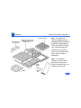
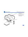
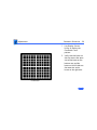
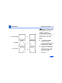
1
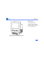
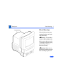
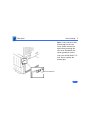
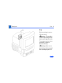
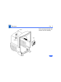
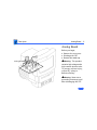
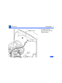
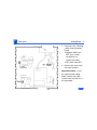
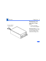
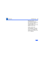
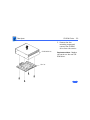
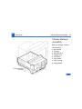
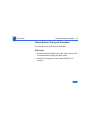
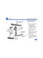
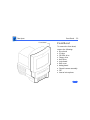
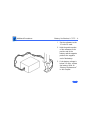
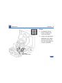
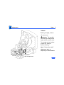
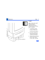
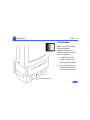
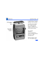
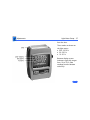
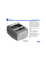
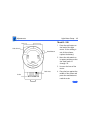
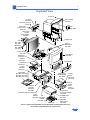
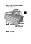
K Service Source
Macintosh LC 520/550/575
Macintosh LC 520, Macintosh LC 550,
Macintosh LC 575
Service Source
Basics
Macintosh LC 520, 550, 575
Basics
Overview - 1
Overview
This manual includes
complete repair procedures
for the LC 520, LC 550, and
LC 575, shown at left.
Figure: Macintosh LC 520, LC 550, LC 575
Basics
Product Information - 2
Product Information
Identifying Features
The LC 575 logic board includes a 68LC040 processor, an
additional communications slot, and a new hook-and-loopattached battery. The LC 520 and LC 550 do not include these
features.
The LC 550 and LC 575 ship with
• the newer manual-inject 1.4 MB Apple SuperDrive and
require the keyhole-shaped bezel.
• a revised chassis harness assembly that does not use a
floppy drive adapter
• the newer, caddyless CD 300+ CD ROM drive
Basics
Product Information - 3
Compatibility Notes
You can exchange the chassis harness assembly of the LC
520 or LC 550 with the newer chassis harness assembly of
the LC 575. The newer chassis harness assembly requires
the manual-inject floppy drive and caddyless CD ROM drive.
K Service Source
Specifications
Macintosh LC 520, 550, 575
Specifications
Processor - 1
Processor
LC 520
LC 550
LC 575
Coprocessor
Motorola 68030 microprocessor
25 MHz
Built-in memory management unit (MMU)
Motorola 68030 microprocessor
33 MHz
Built-in MMU
Motorola 68LC040 microprocessor
33 MHz
Built-in MMU
Socket for optional math coprocessor
Specifications
Memory - 2
Memory
RAM
4 MB of dynamic RAM on board
Expandable to 36 MB (100 ns or faster SIMMs)
72-pin DRAM SIMM connector
ROM
1 MB of ROM
PRAM
256 bytes of clock/calendar/parameter memory
Long-life lithium battery
Specifications
VRAM
Memory - 3
512K of VRAM on board (displays up to 256 colors or 8-bit
color)
Expandable to I MB (displays up to 32,000 colors or 16-bit
color)
68-pin VRAM SIMM connector (LC 520)
Two VRAM SIMM slots (LC 575)
Specifications
Disk Storage - 4
Disk Storage
Floppy Drive
Internal 1.4 MB Apple SuperDrive, auto-inject (LC 520)
Internal 1.4 MB Apple SuperDrive, manual-inject (LC 550 and
LC 575)
Hard Drive
3.5-inch, internal 80, 160, 250, or 320 MB SCSI hard drive
CD-ROM Drive
Internal Apple CD 300i CD-ROM drive (LC 520)
Internal Apple CD 300+ CD-ROM drive (LC 550 and LC 575)
Specifications
I/O Interfaces - 5
I/O Interfaces
Serial
Two RS-232/RS-422 serial ports; mini DIN-8 connectors
SCSI
One SCSI parallel port; DB-25 connector
Connects up to six external SCSI devices
Apple Desktop Bus
Processor-Direct Slot
Two Apple Desktop Bus (ADB) ports; mini DIN-4 connectors
Maximum of three ADB devices recommended
Maximum current draw: 500 mA (Mouse draws 10 mA; keyboard
draws 25 mA.)
Internal expansion slot for 96 or 114-pin processor-direct
expansion cards
Specifications
Communications
Slot (LC 575)
Sound
I/O Interfaces - 6
Internal expansion for 50-pin modem and Ethernet cards
Sound-output port capable of delivering stereo sound
Sound-input port for monaural sound input
Front headphone jack capable of delivering stereo sound
Specifications
I/O Devices - 7
I/O Devices
Keyboard
Standard 80-key Apple keyboard with numeric keypad; ADB
connector
Soft power-on switch
2.5 mm travel, 18 mm vertical and horizontal pitch
Two-level tilt adjustment
Mouse
Apple Desktop Bus Mouse II
New, ergonomic design
Microphone
Built-in electret, omnidirectional microphone
Speaker
Adjustable sound control on front of bezel
Specifications
Sound and Video - 8
Sound and Video
Sound Generator
Video Display
Records at 11 kHz or 22 kHz sample rate
Plays back at 22 kHz sample rate
Two speakers with enhanced stereo sound
Allows playback and recording of ordinary audio compact discs
14-in. diagonal, 13-in. viewable screen
Trinitron CRT with high-contrast glass
.26-mm aperture grille pitch
640 pixels by 480 lines; 70 dpi
Specifications
Electrical - 9
Electrical
Line Voltage
100–240 VAC; Universal power supply
Frequency
47–63 Hz, single phase
Maximum Power
120 W
Specifications
Physical - 10
Physical
Dimensions
Weight
Height: 17.9 in. (45.5 cm)
Width: 13.5 in. (34.4 cm)
Depth: 16.5 in. (42.0 cm)
40.5 lb. (18.4 kg)
Specifications
Environmental - 11
Environmental
Operating
Temperature
Storage
Temperature
50–104° F (10–40° C)
-40 to 149° F (-40 to 65° C)
Relative Humidity
20–95% noncondensing
Altitude
0–10,000 ft. (operating)
K Service Source
Troubleshooting
Macintosh LC 520, 550, 575
Troubleshooting
General/ - 1
General
The Symptom Charts included in this chapter will help you
diagnose specific symptoms related to your product. Because cures
are listed on the charts in the order of most likely solution, try
the first cure first. Verify whether or not the product continues to
exhibit the symptom. If the symptom persists, try the next cure.
(Note: If you have replaced a module, reinstall the original module
before you proceed to the next cure.)
If you are not sure what the problem is, or if the Symptom Charts
do not resolve the problem, refer to the Flowchart for the product
family.
For additional assistance, contact Apple Technical Support.
Troubleshooting
Symptom Charts/Video - 2
Symptom Charts
Video
Screen is black, too
dark, or too bright;
audio and drive
operate
1
2
3
4
5
6
7
Screen is bright and
audio is present, but
no video information
is visible
1
2
3
Adjust contrast button on front bezel.
Adjust brightness. Use Screen Control Panel.
Check yoke cable connection.
Perform video adjustments. Refer to “Video” in Adjustments
chapter.
Perform battery verification.
Replace analog board.
Replace CRT.
Perform video adjustments. Refer to “Video” in Adjustments
chapter.
Replace analog board.
Replace CRT.
Troubleshooting
Symptom Charts/Video (Continued) - 3
Video
Single vertical or
horizontal line is
displayed
(Continued)
Note: A thin, gray, horizontal line may be visible across the
bottom third of a lit screen. This line is inherent in the design of
Trinitron monitors. Do not replace modules.
Otherwise,
1
2
Replace analog board.
Replace CRT.
Predominant color
tint or color cannot be
adjusted
1
Perform video adjustments. Refer to “Video” in Adjustments
chapter.
Replace analog board.
Replace CRT if red, green, or blue cannot be turned off using
appropriate controls.
Black screen spots
(burnt phosphors)
Replace CRT.
2
3
Troubleshooting
Symptom Charts/Video (Continued) - 4
Video
(Continued)
Picture breaks into
diagonal lines, or
picture rolls
vertically or
horizontally
1
Out of convergence
(color bleeds from
text or lines)
1
Flashing or wavy
screen or monitor
emits high-pitched
noise
Replace analog board.
2
2
3
Perform video adjustments. Refer to “Video” in Adjustments
chapter.
Replace analog board.
Perform convergence adjustment. Refer to “Convergence” in
Adjustments chapter.
Replace analog board.
Replace CRT.
Troubleshooting
Symptom Charts/Video (Continued) - 5
Video
Screen jitters or
flashes
1
2
3
4
(Continued)
Verify that adjacent computer equipment is properly
grounded. Move electrical devices away from monitor.
Temporarily shut off all fluorescent lights in area.
Check that all ground cables are secure.
Disconnect internal floppy drive, CD-ROM drive, and hard
drive.
Replace analog board.
Out of focus
1
2
3
Perform focus adjustment. Refer to “Focus” in Adjustments.
Replace analog board.
Replace CRT only if one part of display remains out of focus
despite adjustment of focus controls to their limits.
Raster size too short/
tall or narrow/wide
1
Adjust horizontal or vertical size control. Refer to
Adjustments chapter.
Replace analog board.
2
Troubleshooting
Symptom Charts/Video (Continued) - 6
Video
Linearity bad (size of
text/graphics differs
at top, bottom, or
sides of screen)
1
Raster tilted or
shifted
1
2
2
3
4
(Continued)
Perform video adjustments. Refer to “Video” in Adjustments
chapter.
Replace analog board.
Verify that adjacent computer equipment is properly
grounded. Move electrical devices away from monitor.
Temporarily shut off all fluorescent lights in area.
Perform appropriate geometric adjustments. Refer to
Adjustments chapter.
Perform yoke adjustment. Refer to “Yoke” in Adjustments
chapter.
Replace analog board.
Troubleshooting
Symptom Charts/Video (Continued) - 7
Video
Raster not centered
1
2
3
Raster distorted
(barrel-shaped,
corners not square,
stretched or
compressed at top of
display, or sides not
perpendicular)
1
2
3
4
(Continued)
Verify that adjacent computer equipment is properly
grounded. Move electrical devices away from monitor.
Temporarily shut off all fluorescent lights in area.
Adjust horizontal or vertical center control. Refer to
Adjustments chapter.
Replace analog board.
Verify that adjacent computer equipment is properly
grounded. Move electrical devices away from monitor.
Temporarily shut off all fluorescent lights in area.
Perform appropriate geometric adjustments. Refer to
Adjustments chapter.
Replace analog board.
Replace CRT (only in rare instances).
Troubleshooting
Symptom Charts/Floppy Drive - 8
Floppy Drive
Audio and video are
present, but internal
floppy drive does not
operate
1
2
3
4
5
Replace bad disk with known-good disk.
Replace floppy drive.
Replace logic board. Retain customer’s SIMMs.
Replace floppy drive.
Replace chassis harness cable.
Disk ejects; display
shows icon with
blinking “X”
1
2
3
4
Replace bad system disk with known-good system disk.
Replace floppy drive.
Replace logic board. Retain customer’s SIMMs.
Replace chassis harness cable.
Troubleshooting
Symptom Charts/Floppy Drive (Continued) - 9
Floppy Drive
Does not eject disk
Internal floppy drive
runs continuously
1
2
(Continued)
3
4
Insert opened paper clip into hole beside floppy drive.
Switch off system and hold mouse button down while
switching system on (to complete eject cycle).
Remove front drive bezel.
Replace floppy drive.
1
2
3
4
5
Replace bad disk with known-good disk.
Replace floppy drive.
Replace logic board. Retain customer’s SIMMs.
Replace floppy drive.
Replace chassis harness cable.
Troubleshooting
Symptom Charts/Floppy Drive (Continued) - 10
Floppy Drive
Unable to insert disk
all the way
1
2
3
4
(Continued)
To eject previously inserted disk, insert opened paper clip
into hole beside floppy drive.
Switch off system and hold mouse button down while
switching system on (to complete eject cycle).
Remove front drive bezel.
Replace floppy drive.
Troubleshooting
Symptom Charts/Hard Drive - 11
Hard Drive
Internal or external
hard drive does not
operate
1
2
3
4
5
6
Verify that SCSI loopback card is not attached.
Verify that external drive is properly terminated.
Replace hard drive.
Replace logic board. Retain customer’s SIMMs.
Replace hard drive.
Replace chassis harness cable.
Works with internal
or external SCSI
device but does not
work with both
1
Verify that SCSI device ID switch setting on external device
is higher than 0. Also verify that ID switch setting on
external SCSI device does not duplicate ID switch settings on
any other attached external SCSI devices.
Replace terminator on external SCSI device.
Replace SCSI select cable.
2
3
Troubleshooting
Symptom Charts/CD-ROM Drive - 12
CD-ROM Drive
CD-ROM drive does
not accept disc
1
2
3
Replace disc (if dirty or damaged).
Remove front drive bezel.
Replace CD-ROM drive mechanism.
Volume control does
not operate correctly
1
2
Reset PRAM.
Replace chassis harness assembly.
Macintosh cannot
mount CD-ROM drive
1
2
Verify proper CD-ROM software is installed.
Start up from known-good system, Disk Tools, or external
SCSI device.
Replace CD-ROM drive mechanism.
3
Troubleshooting
Symptom Charts/Peripheral - 13
Peripheral
Cursor does not move
Cursor moves, but
clicking mouse
button has no effect
1
2
3
4
5
6
Check mouse connection.
If mouse was connected to keyboard, connect it to rear ADB
port instead. If mouse works, replace keyboard.
If mouse does not work in any ADB port, replace mouse.
Reset PRAM.
Remove additional PDS and CS cards.
Replace logic board. Retain customer’s SIMMs.
1
2
Replace mouse.
Replace logic board. Retain customer’s SIMMs.
Troubleshooting
Symptom Charts/Peripheral (Continued) - 14
Peripheral
Cannot double-click
to open application,
disk, or server
1
2
4
5
Remove extra system files on hard drive.
Clear parameter RAM. Hold down <Command> <Option> <P>
<R> keys during system startup but before “Welcome to
Macintosh” appears.
If mouse was connected to keyboard, connect it to rear ADB
port instead. If mouse works, replace keyboard.
If mouse does not work in any ADB port, replace mouse.
Replace logic board. Retain customer’s SIMMs.
1
2
3
4
5
Check keyboard connection to ADB port.
Replace keyboard cable.
Replace keyboard.
Reset PRAM.
Replace logic board. Retain customer’s SIMMs.
3
No response to any
key on keyboard
(Continued)
Troubleshooting
Symptom Charts/Peripheral (Continued) - 15
Peripheral
Known-good
ImageWriter or
ImageWriter II does
not print
1
2
Known-good
LaserWriter does not
print
1
2
3
4
5
3
4
(Continued)
Make sure that Chooser and Control Panel are set correctly.
Replace printer driver and system software with knowngood.
Reset PRAM.
Replace printer interface cable.
Replace logic board. Retain customer’s SIMMs.
Make sure that Chooser and Control Panel are set correctly.
Replace printer driver and system software with knowngood.
Reset PRAM.
Refer to Networks and Communications manual.
Troubleshooting
Symptom Charts/Miscellaneous - 16
Miscellaneous
Clicking, chirping,
or thumping sound
1
2
Replace analog board.
Replace logic board. Retain customer’s SIMMs.
Smoke/odor
1
2
Inspect analog board and logic board for any signs of burnt
components.
Replace analog board.
1
2
3
4
5
6
Connect power cord.
Switch power on.
Replace power cord.
Replace keyboard.
Replace analog board.
Replace logic board. Retain customer’s SIMMs.
No video, no audio, and
no drive operation
Troubleshooting
Symptom Charts/Miscellaneous (Continued) - 17
Miscellaneous
(Continued)
Screen shows “Sad
Macintosh” icon and
black vertical lines;
screeching sound
1
2
Replace RAM SIMMs on logic board.
Replace logic board. Retain customer’s SIMMs.
Headphone jack does
not operate correctly
1
2
Verify that headphone jack is seated properly.
Replace chassis harness assembly.
Speaker jacks do not
operate
1
2
Verify that speaker jacks are seated properly.
Replace logic board.
System automatically
restarts after
shutdown
Check whether test jumper is installed on analog board (location:
BD 11). If it is installed, remove it.
Troubleshooting
Symptom Charts/Miscellaneous (Continued) - 18
Miscellaneous
“Sad Macintosh” icon
1
2
3
4
(Continued)
Replace bad disk with known-good disk.
Disconnect internal and external IDE or SCSI devices. If the
flashing “?” appears, re-attach devices one at a time.
Troubleshoot software issue on device that produces problem.
Replace RAM SIMMs on logic board.
Replace logic board. Retain customer’s SIMMs.
K Service Source
Take Apart
Macintosh LC 520, 550, 575
Take Apart
Rear Housing
Rear Housing - 1
Rear Housing
No preliminary steps are
required before you begin
this procedure.
Warning: This product
contains high voltage and a
high-vacuum picture tube.
To prevent serious injury,
review CRT safety in
Bulletins/Safety.
±
Never use a
grounding wriststrap until
after discharging the CRT.
±Warning:
Take Apart
Rear Housing - 2
Note: If the rear cover has
bronze tape on the rear
cover shield, remove the
tape before removing the
rear cover. Bend back the
center ground pin on the
rear cover shield about 1/8
inch. Do not replace the
bronze tape.
Center Ground Pin
Take Apart
Rear Housing
Rear Housing - 3
1
2
Using a Torx
screwdriver, remove
the five screws.
Lift off the rear cover.
Take Apart
Fan - 4
Fan
Fan
Before you begin, remove
the rear cover.
This product
contains high voltage and a
high-vacuum picture tube.
To prevent serious injury,
review CRT safety in
Bulletins/Safety.
±Warning:
Warning: Never use a
grounding wriststrap until
after discharging the CRT.
±
Take Apart
Fan - 5
P ush out the two latches and
remove the fan assembly.
Latch
Latch
Fan
Take Apart
Analog Board - 6
Analog Board
Before you begin,
• Remove the rear cover
• Discharge the CRT
• Remove the anode cap
Analog Board
This product
contains high voltage and a
high-vacuum picture tube.
To prevent serious injury,
review CRT safety in
Bulletins/Safety.
±Warning:
Warning: Never use a
grounding wriststrap until
after discharging the CRT.
±
Take Apart
Analog Board - 7
Degauss Panel
Ground Cable
Ground
Cable
1
Disconnect the two
ground cables from the
degauss panels.
Take Apart
Analog Board - 8
2
Internal
Microphone
Connector
WARNING:
High Voltage Areas
Disconnect the internal
microphone connector.
Take Apart
Analog Board - 9
3
Cable
Retainer
4
Disconnect the following
cables from the analog
board:
• Degauss cable from
BP2 (use a small
screwdriver to
release the latch)
• CRT cable from BD1
Remove the wires from
the cable retainer.
Replacement Note: If you
are replacing the analog
board, remove the cable
retainer and reinstall it on
the new board.
Take Apart
Analog Board - 10
5
CRT Board Assembly
Caution: Twisting,
bending, or applying
force to the video board
assembly could damage
the neck of the CRT. Be
sure to pull the CRT
board assembly straight
off the CRT.
Remove the CRT board
assembly from the neck
of the CRT.
Take Apart
Analog Board - 11
6
Analog
Board
Remove the analog board.
Replacement Note: Some
analog boards may include a
test jumper (located at BD
11). To avoid restart
problems, remove this
jumper from the existing
or replacement analog board.
Replacement Note: Perform
the cutoff adjustment
whenever you replace the
analog board. See “Video” in
the Adjustments chapter.
Take Apart
I/O Door - 12
I/O Door
No preliminary steps are
required before you begin
this procedure.
I/O Door
Caution: Review the ESD
precautions in Bulletins/
Safety.
Take Apart
I/O Door - 13
1
2
Tab
Tab
I/O
Door
Remove the two screws.
Push down on the two
tabs and remove the I/O
door.
Take Apart
Logic Board - 14
Logic Board
Before you begin, remove
the I/O door.
Logic Board
Caution: You can access and
remove the LC 520 logic
board merely by removing
the I/O door at the rear of
the machine. Although
upgrading the logic board is
now extremely easy, do not
neglect to follow proper
ESD precautions: use a
grounded workbench pad,
and always wear a
grounding wriststrap.
Take Apart
Logic Board - 15
Pull out the logic board.
Logic
Board
Take Apart
Drive Bezel - 16
Drive Bezel
No preliminary steps are
required before you begin
this procedure.
Caution: Review the ESD
precautions in Bulletins/
Safety.
Drive
Bezel
Take Apart
Drive Bezel - 17
Using a flat-blade
screwdriver, push up the
latch. Pull down and remove
the drive bezel.
Latch
Drive
Bezel
Take Apart
Floppy Drive - 18
Floppy Drive
Before you begin, remove
the drive bezel.
Floppy
Drive
Caution: You can access and
remove the floppy drive
merely by removing the
drive bezel at the front of
the machine. Although
replacing the floppy drive is
now extremely easy, do not
neglect to follow proper
ESD precautions: use a
grounded workbench pad,
and always wear a
grounding wriststrap.
Take Apart
Floppy Drive - 19
Note: The LC 520 includes
an auto-inject 1.4 MB
floppy drive and a chassis
harness assembly that
requires a floppy drive
connector adapter. The LC
550 and 575 include
manual-inject 1.4 MB
floppy drives and chassis
harness assemblies that
allow the floppy drive cable
to connect directly to the
drive.
Take Apart
Floppy Drive - 20
Push down the latch and pull
out the floppy drive.
Floppy
Drive
Latch
Take Apart
Connector Adapter
(LC 520 Only)
Floppy Drive - 21
Macintosh LC 520
Auto-inject Floppy
Drive
1
Pull out the floppy
drive connector adapter
Replacement Note: Be sure
to reinstall the floppy drive
connector adapter on the
replacement floppy drive.
Take Apart
Floppy Drive - 22
Auto-inject
Floppy Drive
and Shield
Auto-inject Floppy
Drive Carrier
2
Remove the four
mounting screws and
remove the floppy drive
from the carrier.
Take Apart
Floppy Drive - 23
3
Auto-inject
Floppy Drive
Shield
Auto-inject
Floppy Drive
Pull out the sides of the
floppy drive shield, lift
the back of the shield,
and remove it from the
floppy drive.
Take Apart
Floppy Drive - 24
Manual-Inject
Floppy Drive
Macintosh LC 550 and
575 Manual-inject
Floppy Drive
Remove the four mounting
screws and remove the
floppy drive from the
carrier.
Note: Do not remove the
metal case from the manualinsert floppy drive in the LC
550 and LC 575.
Manual-inject
Floppy Drive
Take Apart
CD-ROM Drive - 25
CD-ROM Drive
Before you begin, remove
the drive bezel.
Caution: You can access and
remove the CD-ROM drive
merely by removing the
drive bezel at the front of
the machine. Although
upgrading the CD-ROM drive
is now extremely easy, do
not neglect to follow proper
ESD precautions: use a
grounded workbench pad,
and always wear a
grounding wriststrap.
CD-ROM Drive
Take Apart
CD-ROM Drive - 26
1
CD-ROM
Drive
Latch
Pull up the latch and
pull out the CD-ROM
drive.
Take Apart
CD-ROM Drive - 27
2
CD Connector
or Hard Drive
Adapter
CD Audio Adapter
Pull out the CD
connector adapter and
the CD audio adapter.
Replacement Note: Be sure
to reinstall the CD connector
adapter on the replacement
CD-ROM drive.
Take Apart
CD-ROM Drive - 28
Replacement Note: Be sure
to reinstall the correct
drive connector adapter and
CD audio adapter. The
adapters used for the LC 520
and LC 575 are very
similar, but are not
interchangeable. The bases
of the LC 520 adapters are
shorter than the bases of the
LC 575 adapters.
Take Apart
CD-ROM Drive - 29
3
CD-ROM Drive
Carrier
Remove the four
mounting screws and
remove the CD-ROM
drive from the carrier.
Replacement Note: Replace
the carrier on the new CDROM drive.
Take Apart
Hard Drive - 30
Hard Drive
Before you begin, remove
the I/O door.
Hard Drive
Caution: You can access and
remove the LC 520 hard
drive merely by removing
the I/O door at the rear of
the machine. Although
upgrading the hard drive is
now extremely easy, do not
neglect to follow proper
ESD precautions: use a
grounded workbench pad,
and always wear a
grounding wriststrap.
Take Apart
Hard Drive - 31
1
Hard Drive
Latch
Push down the latch and
remove the hard drive.
Take Apart
Hard Drive - 32
2
Pull out the hard drive
connector adapter.
Replacement Note: Be
sure to reinstall the
hard drive connector
adapter on the
replacement hard drive.
Hard Drive
Connector
Adapter
Take Apart
Hard Drive - 33
3
4
Carrier
Hard
Drive
Remove the four screws.
Remove the hard drive
from the carrier.
Replacement Note: Replace
the carrier on the new hard
drive.
Take Apart
Chassis Harness Assembly - 34
Chassis Harness
Assembly
Before you begin, remove
the following:
• Drive bezel
• I/O door
• CD-ROM drive
• Floppy drive
• Hard drive
• Logic board
• Rear housing
• Analog board
Chassis Harness
Assembly
Take Apart
Chassis Harness Assembly - 35
This product
contains high voltage and a
high-vacuum picture tube.
To prevent serious personal
injury or equipment
damage, review CRT safety
in Bulletins/Safety.
±Warning:
Chassis
Harness
Assembly
Latches
Never use a
grounding wriststrap until
after discharging the CRT.
±Warning:
1
Latches
2
Discharge the CRT.
Press in the four
latches and lift off the
chassis harness
assembly.
Take Apart
Chassis Harness Assembly - 36
Chassis Harness Take Apart Strategy
Background
After product introduction, Apple Service adjusted the
service strategy for the chassis harness assembly in Mac
TV, LC 500 Series, and Performa 500 Series computers.
Originally, the chassis harness assembly was a single
service assembly. As of November 1994, the chassis
harness assembly is divided into several service piece parts.
Identifying the Chassis Harness Assembly
There are three slightly different chassis harness
assemblies and Apple service strategy varies with the type
of chassis. The three chassis harness assemblies differ
according to the combination of floppy and CD-ROM drives
they support.
Take Apart
Chassis Harness Assembly - 37
• Chassis 922-1824 supports the auto-insert Apple
SuperDrive and CD-ROM drives earlier than the 300i+.
This chassis requires a floppy drive adapter, and the CDROM connector bridge is about 1-1/2 inches above the
CD-ROM drive bay.
• Chassis 922-0557 supports the manual-insert Apple
SuperDrive and CD-ROM drives earlier than the 300i+.
This chassis uses a ribbon cable to connect the floppy
drive, and the CD-ROM connector bridge is about 1-1/2
inches above the CD-ROM drive bay.
• Chassis 661-1094 supports the manual-insert Apple
SuperDrive and the 300i+ CD-ROM drive. This chassis
uses a ribbon cable to connect the floppy drive, but the
CD-ROM connector bridge is only 1/2 inch above the CDROM drive bay.
Take Apart
Chassis Harness Assembly - 38
For more information, refer to Apple Service Guide,
Macintosh Computers, Vol. 3 (1994), page 110.
Service Parts Now Available for Chassis 922-1824 and
922-0557
661-0981 Shield Kit (EMI shielding)
922-1825 PCBA Front Panel (front panel control board)
922-1826 Speaker Assembly (speaker and wire)
922-0117 Screw
076-0489 Chassis Kit (bare chassis)
922-0503 FoxConn Cable Assembly (logic board connector
and cable assembly)
Take Apart
Chassis Harness Assembly - 39
Service Parts Now Available for Chassis 661-1094
661-0981 Shield Kit (EMI shielding)
922-1825 PCBA Front Panel (front panel control board)
922-1826 Speaker Assembly (speaker and wire)
922-0117 Screw
Take Apart
Chassis Harness Assembly - 40
Chassis Harness Take Apart Procedures
First remove the chassis harness assembly.
EMI Shields
1
2
Remove the EMI shields in this order: lower shield, front
drive and speaker shield, top panel shield.
Remove the front panel control board shield if it is
present.
Take Apart
Chassis Harness Assembly - 41
Speaker Assembly
First remove the EMI
shields.
Caution: The speaker wire
connections on the chassis
cable bridge are very
fragile. Avoid removing or
replacing the speaker wires
unless you need to replace
the chassis or have isolated
the problem to the speaker
wires. (That is, replace and
test the speakers, front
panel control board, and
analog board first.)
Take Apart
Chassis Harness Assembly - 42
1
2
Disconnect the speaker wire spade connector from the
back of the speaker.
Remove the Phillips screws from the front of the
speaker.
Replacement Note: Detach the replacement speaker from its
wires and connect the replacement speaker to the original
speaker wires.
Speaker Wires
Note: The speaker wire connectors are very fragile.
1
2
Look down on the chassis cable bridge and locate the
notches in the cable bridge on top of the wire connectors.
Using a jeweler's screwdriver, very gently press down
on the tab in the middle of the wire connector. You will
feel or hear a snap.
Take Apart
Chassis Harness Assembly - 43
3
Slide out the wire connector.
Replacement Note: The analog board slides into the
computer and completes the connection to the speaker wires;
thus, the speaker wire connectors must sit securely in the
cable bridge.
4
Slide the speaker wire connector into its position in the
cable bridge and press up until the connector is secure.
You may need to use a jeweler's screw driver to adjust
the small metal tab in the center of the speaker wire
connector.
Take Apart
Chassis Harness Assembly - 44
Front Panel Control Board
First remove the EMI
shields.
1
2
Disconnect the front
panel control cable.
Remove the Phillips
screw and remove the
board.
Take Apart
Chassis Harness Assembly - 45
Logic Board Connector and Cable Assembly
First remove the EMI shields, speaker assembly, and front
panel control board.
Overview of removal procedures (Detailed steps follow the
overview.)
First disconnect all the connections from the top of the
chassis. Then route the cables through to the underside of the
chassis and disconnect the logic board connector.
Take Apart
Chassis Harness Assembly - 46
1
Hard
Drive
Connector
CD-ROM
Connector
Left
Speaker
Cable
Connector
Right
Speaker
Cable
Connector
Analog
Board
Connector
Bridge
Cable
Floppy Drive Connector
Stand at the front of the
chassis, looking down at
the top of the chassis,
and disconnect the
following in the order
listed: analog board
connector, CD-ROM
drive connector, and
hard drive connector.
(The connector tabs
operate much like largescale SIMM slot
connectors on logic
boards.)
Take Apart
Chassis Harness Assembly - 47
2
3
4
5
Route the analog board and the CD-ROM/hard drive
cables through the large square hole behind the CD-ROM
drive bay.
Push the floppy drive cable (if present) and front panel
control cable to the underside of the chassis.
Turn the chassis over and stand at the rear of the chassis.
Release the three tabs from the sides and center of the
logic board connector and remove the logic board
connector and cable assembly.
Take Apart
Chassis Harness Assembly - 48
Overview of replacement procedures (Detailed steps follow
the overview.)
Connect the logic board connector to the underside of the
chassis, route the cables through the appropriate openings,
and connect the connectors on the top and front of the chassis.
After replacing the logic board connector and cable
assembly, replace the speakers, front panel control board,
and EMI shields.
1
Place the chassis with the underside facing up and the
speakers facing away from you.
Take Apart
Chassis Harness Assembly - 49
2
Analog
Board
Connector
Logic
Board
Connector
CD-ROM
Drive Cable/
Hard Drive
Cable
Control
Panel
Cable
Floppy
Drive
Cable
3
Arrange the logic board
connector and cable
assembly as shown.
Face the connector slot of
the logic board connector
toward the rear and from
the back of the
connector route the CDROM/hard drive,
analog, and floppy drive
cables under the
connector. Extend the
control panel connector
cable from the back of
the logic board connector
toward the front of the
chassis.
Take Apart
Chassis Harness Assembly - 50
Logic Board Connector
and Cable Assembly
1
2
Slide the side extension
of the logic board
connector down the
front side of the small
keyed tabs. The logic
board connector will
snap into place.
Note: Be sure the center
tab snaps into place at
the same time.
Route the front panel
control cable through the
hole in the front of the
chassis
Take Apart
Chassis Harness Assembly - 51
3
4
5
Route the floppy drive cable through its opening at the
back of the floppy drive bay.
Carefully route the analog and CD-ROM/hard drive
cables through the large opening behind the CD-ROM
drive bay
Turn over the chassis so that the top is up and the
speakers are at the front, facing you.
Important: Be sure to reconnect the CD-ROM, hard drive,
and analog connectors in the proper order. When you
position the CD-ROM, hard drive, and analog connectors, be
sure that the power cables are placed toward the outside of
the chassis and the data ribbon cables are placed toward the
inside of the chassis.
6
7
Locate the CD-ROM, hard drive, and analog connectors.
Position the CD-ROM connector with the connector slot
Take Apart
Chassis Harness Assembly - 52
8
9
facing the front of the chassis and the power cables
facing toward the outside edge of the chassis. Slip the
connector extension through the slot in the side of the
chassis and slide the connector into place.
Position the hard drive connector with the connector slot
facing the rear of the chassis and the power cables facing
toward the outside edge of the chassis. Slip the connector
extension through the slot in the side of the chassis and
slide the connector into place.
Position the analog board connector with the connector
slot facing the rear and the power cables facing toward
the outside edge of the chassis. You will have to route the
cable under the connector (between the connector and the
cable bridge). Slightly push forward one of the keyed
tabs and slide the connector into place.
Take Apart
Chassis Harness Assembly - 53
10 To replace the speakers, front control panel board, and
EMI shields, reverse the take-apart procedures above.
Pay attention to the caution regarding the fragility of the
speaker wire connectors and their replacement
procedures.
Take Apart
CRT - 54
CRT
CRT
Before you begin, remove
the following:
• Drive bezel
• I/O door
• CD-ROM drive
• Floppy drive
• Hard drive
• Logic board
• Rear cover
• Analog board
• Chassis harness assembly
Take Apart
CRT - 55
Mounting Screws
Degauss
Panel
This product
contains high voltage and a
high-vacuum picture tube.
To prevent serious injury,
review CRT safety in
Bulletins/Safety.
±Warning:
Degauss
Panel
Never use a
grounding wriststrap until
after discharging the CRT.
±Warning:
1
Remove the four
mounting screws and
lift off the two degauss
panels.
Take Apart
CRT - 56
2
Lift off the CRT.
Replacement Note: Be sure
the microphone cable is not
caught under the CRT.
CRT
Microphone Cable
Take Apart
Internal Microphone - 57
Internal Microphone
Internal
Microphone
Before you begin, remove
the following:
• Drive bezel
• I/O door
• CD-ROM drive
• Floppy drive
• Hard drive
• Logic board
• Rear cover
• Analog board
• Chassis harness assembly
• CRT
Take Apart
Internal Microphone - 58
This product
contains high voltage and a
high-vacuum picture tube.
To prevent serious injury,
review CRT safety in
Bulletins/Safety. Never use
a grounding wriststrap until
after discharging the CRT.
±Warning:
Push out the two latches and
remove the internal
microphone board and the
rubber microphone gasket.
Replacement Note: Be sure
the rubber gasket is in place
before replacing the
microphone board.
Take Apart
Front Bezel - 59
Front Bezel
Front Bezel
To remove the front bezel,
remove the following:
• Drive bezel
• I/O door
• CD-ROM drive
• Floppy drive
• Hard drive
• Logic board
• Rear cover
• Analog board
• Chassis harness assembly
• CRT
• Internal microphone
Take Apart
Front Bezel - 60
This product
contains high voltage and a
high-vacuum picture tube.
To prevent serious injury,
review CRT safety in
Bulletins/Safety.
±Warning:
Front Bezel
Never use a
grounding wriststrap until
after discharging the CRT.
±Warning:
K Service Source
Upgrades
Macintosh LC 520, 550, 575
Upgrades
Macintosh Processor Upgrade - 1
Macintosh Processor Upgrade
(including 256K Cache Card)
Macintosh
Processor Upgrade
Before you begin, remove
the following:
• I/O door
• Logic board
• Card in PDS slot (if any)
Caution: Review the ESD
precautions in Bulletins/
Safety.
Upgrades
Macintosh Processor Upgrade - 2
Note: The Macintosh
Processor Upgrade kit
allows 68LC040 computers
to switch between a
PowerPC 601 processor
and a 68LC040 processor.
The upgrade board includes
the PowerPC 601 processor
on board and a socket to
accept the customer’s
68LC040 processor.
Upgrades
Macintosh Processor Upgrade - 3
Note: The PowerPC upgrade
for the Macintosh LC 520
and 550 consists of a
Macintosh LC 575 logic
board, the PowerPC
Upgrade Card, a new rear
panel, and the 575 product
ID label.
To install this upgrade,
follow the Macintosh LC 575
PowerPC Upgrade
procedures in this topic,
substituting the 575 logic
board, rear panel, and ID
label for those installed on
the Macintosh LC 520 and
550.
Upgrades
Macintosh Processor Upgrade - 4
Note: Refer to the Macintosh
Processor Upgrade manual
for information about
specifications and
troubleshooting.
Upgrades
Macintosh Processor Upgrade - 5
Macintosh Processor
Hook-and-Loop Upgrade with 256K
Cache Card
Fasteners
040 Heat Sink
256K
Cache
Card
Spacer
Processor
Removal
Tool
Note: The Macintosh
Processor Upgrade comes
packaged with the Macintosh
Processor Upgrade board,
256K cache card, 040 heat
sink, and hook-and-loop
fasteners. If you need to
order service replacement
parts, order the parts
separately.
Note: To install the
upgrade, you will need a
processor removal tool.
Order the removal tool as a
separate service part.
Upgrades
Macintosh Processor Upgrade - 6
Note: The cache card comes
installed on the upgrade
board.
Upgrades
Macintosh Processor Upgrade - 7
Installation Procedure
Overview
These are the basic steps to
installing the Macintosh
Processor Upgrade.
• Remove the 68LC040
processor from the
customer’s logic board
• Install the 68LC040
processor on the upgrade
board
• Prepare the upgrade and
logic boards for
installation
• Install the upgrade board
on the logic board
Upgrades
Macintosh Processor Upgrade - 8
• Reinstall the cache card
on the upgrade board
Detailed procedures follow.
Upgrades
Macintosh Processor Upgrade - 9
Remove the 68LC040
Processor from the
Logic Board
1
68LC040
Processor
Locate the 68LC040
processor on the logic
board.
Upgrades
Macintosh Processor Upgrade - 10
Processor
Processor
2
Position the teeth of the
processor removal tool
in the groove between
the processor and the
logic board socket.
Caution: Be sure to lift
up on the handle of the
processor removal tool.
Pressing down could
damage components on
the logic board.
Processor
Removal Tool
Logic Board Socket
Upgrades
Macintosh Processor Upgrade - 11
Processor
Processor
Note: This graphic shows
the proper way to remove a
68LC040 chip from its logic
board. Your logic board may
differ somewhat from this
graphic.
3
Processor
Removal Tool
Logic Board Socket
4
Caution: Pry up each
side of the processor
only slightly to avoid
bending the pins.
Gently lift up the
processor removal tool
handle and pry up each
side of the processor
from the socket.
Remove the processor.
Upgrades
Macintosh Processor Upgrade - 12
Spacer
Install the 68LC040
Processor on the
Upgrade Board
Note: The alignment corner
of the 68LC040 processor is
missing one pin. The
alignment corner of the
spacer is missing a pin hole.
1
Alignment Corners
68LC040
Processor
2
Position the spacer
alignment corner over
the 68LC040 processor
alignment corner
Place the spacer on the
processor.
Upgrades
Macintosh Processor Upgrade - 13
Caution: Forcing the
68LC040 processor
connector pins into the
socket could damage the pins.
If the processor resists
installation, check the pin
alignment.
68LC040
Processor
Caution: Place the upgrade
board on a firm even surface
to avoid bending the upgrade
board when pressing the
processor into the socket.
Caution: Use two thumbs to
evenly distribute the
pressure as you press the
processor into the socket.
Upgrades
Macintosh Processor Upgrade - 14
3
4
Hold the processor and
spacer together and
position the spacer
alignment corner over
the upgrade socket
alignment corner.
Press the processor
connector pins into the
socket until you hear a
“snap.”
Upgrades
Macintosh Processor Upgrade - 15
Note: On a correctly
installed 040 processor, a
very small gap separates the
040 chip from the metal
spacer. A larger gap caused
by the barrel sockets of the
upgrade board separates the
upgrade board and the
spacer.
040 Processor
Small Gap
Barrel
Sockets
Spacer
Upgrades
Macintosh Processor Upgrade - 16
Prepare the Upgrade
and Logic Boards for
Installation
Note: The following steps
explain how to prepare the
upgrade board and logic
board to connect with each
other.
1
Upgrade
Board
256K Cache
Card
Remove the 256K cache
card from the upgrade
board.
Upgrades
Macintosh Processor Upgrade - 17
Note: You will reinstall the
cache card after the upgrade
board connects to the logic
board.
Caution: The EMI clips on
the bottom of the LC 575
logic board flex easily. Do
not apply heavy pressure
directly to these clips or you
may bend the logic board.
Antistatic Foam
Logic Board,
Bottom Side
EMI Clips
Upgrades
Macintosh Processor Upgrade - 18
2
3
Hook-and-Loop
Fastener
Note: This step helps
prevent the logic board
from bending when you
apply pressure in the
next few steps.
Place a piece of
antistatic foam directly
under the processor
socket on the bottom
side of the logic board.
Peel the tape from the
remaining sides of the
two hook-and-loop
fasteners. Afix the
fastener in the position
shown on the logic board.
Upgrades
Macintosh Processor Upgrade - 19
Battery
4
Note: This step makes
room for the processor
upgrade board.
Move the battery from
its original hook-andloop fastener to the
fastener on the chip
behind the ADB ports.
Hook-and-Loop
Fastener
Upgrades
Macintosh Processor Upgrade - 20
CHANGE
Upgrade Connector
Alignment Corner
Install the Upgrade
Board on the Logic
Board
Caution: Forcing the
upgrade board connector
pins into the logic board
socket could damage the pins.
If the connector resists
installation, check the pin
alignment.
1
Logic Board Socket
Alignment Corner
Position the upgrade
connector alignment
corner over the logic
board socket alignment
corner.
Upgrades
Macintosh Processor Upgrade - 21
2
3
Carefully align the pins
along all sides of the
processor and socket.
Firmly press the
connector pins into the
logic board socket.
Upgrades
Macintosh Processor Upgrade - 22
Note: After you install the
upgrade board, connect the
battery cable through the
hole in the upgrade board
and reinstall the cache card.
PowerPC Heat Sink
4
5
r Hole
y for
Battery
Connector
Drop the battery
connector through the
hole in the upgrade board
and connect the battery
to the logic board.
Caution: The heat of the
heat sink can melt the
battery cable.
Route the battery cable
to avoid contact with the
heat sink.
Battery Cable
Upgrades
Macintosh Processor Upgrade - 23
6
7
Processor
Upgrade
Board
Long Row of Pins
Long Pin Socket
Note: There are two
sockets on the cache
card.
Align the longer cache
card socket with the
longer row of pins on the
upgrade board.
Firmly press the cache
card onto the upgrade
board.
Note: To install the
software, refer to the
upgrade Owner’s Guide.
Cache
Card
Upgrades
Macintosh Processor Upgrade - 24
Logic Board and
Upgrade Board
Returns
Return the upgrade and
logic boards to their original
conditions before sending
them to Apple. Be sure to
remove the upgrade board
from the logic board and
reinstall the 68LC040
processor on the logic board.
Replacement Caution: To
avoid bending any pins when
removing the 68LC040
processor, pry up each side
only slightly.
K Service Source
Additional Procedures
Macintosh LC 520, 550, 575
Additional Procedures
Battery Verification, LC 520 - 1
Battery
Verification, LC
520
Before you begin, remove
the following:
• I/O door
• Logic board
If handled or
discarded improperly, the
lithium battery in the
computer could explode.
Review battery handling and
disposal instructions in
Bulletins/Safety.
±Warning:
Battery
Additional Procedures
Battery Verification, LC 520 - 2
Caution: Review the ESD
precautions in Bulletins/
Safety.
1
Negative
Probe
2
Positive
Probe
3
Set the voltmeter to the
10 volts DC scale.
Hold the positive probe
of the voltmeter to the
positive end of the
battery and the negative
probe to the negative
end of the battery.
If the battery voltage is
below 3.0 volts, replace
the battery. Refer to
“Battery Replacement”
in this chapter.
Additional Procedures
Battery
Battery Verification, LC 575 - 3
Battery
Verification, LC
575
Before you begin, remove
the following:
• I/O door
• Logic board
• Battery
Caution: Review the ESD
precautions in Bulletins/
Safety.
Additional Procedures
Battery Verification, LC 575 - 4
1
2
3
Set the voltmeter to the
10 volts DC scale.
Hold the positive probe
of the voltmeter to the
positive end of the
battery and the negative
probe to the negative
end of the battery.
If the battery voltage is
below 3.0 volts, replace
the battery. Refer to
“Battery Replacement”
in this chapter.
Additional Procedures
Battery Replacement, LC 520 - 5
Battery
Replacement, LC
520
Before you begin, remove
the following:
• I/O door
• Logic board
If handled or
discarded improperly, the
lithium battery in the
computer could explode.
Review battery handling and
disposal instructions in
Bulletins/Safety.
±Warning:
Battery
Additional Procedures
Battery Replacement, LC 520 - 6
Caution: Review the ESD
precautions in Bulletins/
Safety.
1
Cover
Battery
Holder
2
Insert a small flatblade screwdriver into
the top of the battery
holder cover and gently
push down and out with
the screwdriver to
release the tab.
Repeat on the other end
and remove the cover
from the battery holder.
Additional Procedures
Battery Replacement, LC 520 - 7
3
4
Grasp the battery and
remove it from the
holder.
Return the battery to
Apple for proper
disposal. For battery
packaging and labeling
instructions, refer to
the safety information in
Bulletins/Safety.
Additional Procedures
Battery
Battery Replacement, LC 575 - 8
Battery
Replacement, LC
575
Before you begin, remove
the following:
• I/O door
• Logic board
Caution: Review the ESD
precautions in Bulletins/
Safety.
Additional Procedures
Battery Replacement, LC 575 - 9
1
2
Battery
Connector
Hook-and-Loop
Base
Pull up and disconnect
the connector.
Pull up and remove the
battery from its hookand-loop base.
K Service Source
Adjustments
Macintosh LC 520, 550, 575
Adjustments
Geometry - 1
Geometry
Before you begin, remove
the rear cover.
This product
contains high voltage and a
high-vacuum picture tube.
To prevent serious injury,
review CRT safety in
Bulletins/Safety.
±Warning:
Adjustment
Controls
WARNING:
High Voltage Areas
Adjustments
Geometry - 2
Note: The controls on this
monitor require a small
hex-head plastic tool to
make adjustments. If the tool
is long, it will be too
flexible, which will make
fine adjustments difficult.
Use a short hex-head
plastic tool to minimize
flexing.
Do not use
metal alignment tools—they
are a shock hazard.
±Warning:
Adjustments
Geometry - 3
Vertical Center
1
All-White Screen
2
Use Display Service
Utility to display the
All-White Screen test
pattern.
Using a hex-head plastic
adjustment tool, adjust
the vertical center (VS)
control until the raster
is centered (top to
bottom) in the display
area.
Adjustments
Geometry - 4
Horizontal Center
All-White Screen
Using a hex-head plastic
adjustment tool, adjust the
horizontal center (HS)
control until the raster is
centered (side to side) in the
display area.
Adjustments
Geometry - 5
Vertical Size
1
All-White Screen
2
Using a hex-head plastic
adjustment tool, adjust
the vertical height (VH)
control until the raster
height is 7 inches
(± 1/8 inch) or 176
mm (± 2 mm).
Verify this height. If it
is off, repeat the
vertical size adjustment
and, if necessary, the
vertical center
adjustment.
Adjustments
Geometry - 6
Horizontal Size
All-White Screen
Note: Due to video features
and timing differences
across the Apple line of
Macintosh computers, the
width of the raster/image
area on the Macintosh LC
520 screen may vary up to
3/16 inch at each side of the
screen. Perform the
horizontal size adjustment
to set the display to its
proper width.
Adjustments
Geometry - 7
Using a hex-head plastic
adjustment tool, adjust the
horizontal width (HW)
control until the raster is
9 1/4 inches (± 1/8 inch)
or 235 mm (± 2 mm).
Adjustments
Geometry - 8
Focus
1
Focus
Focus
WARNING:
High Voltage Areas
2
Use Display Service
Utility to display the
Focus test pattern.
Using a hex-head plastic
adjustment tool, adjust
the focus control until
the Focus test pattern is
as clear as possible.
Adjustments
Video - 9
Video
Before you begin, remove
the rear cover.
This product
contains high voltage and a
high-vacuum picture tube.
To prevent serious injury,
review CRT safety in
Bulletins/Safety.
±Warning:
Note: Perform the cutoff
adjustment prior to
adjusting the white balance.
Adjustment
Controls
WARNING:
High Voltage Areas
Adjustments
Video - 10
Replacement Note: Perform
the cutoff adjustment
whenever you replace the
CRT or the analog board.
Adjustments
Video - 11
Cutoff
Gray Bars
Note: Perform the cutoff
and white balance
adjustments after the
monitor has been on for at
least 10 minutes.
1
2
3
Contrast Up Button
Use Display Service
Utility to display the
Gray Bars test pattern.
Press the Contrast Up
button and set screen
contrast to maximum.
Select the Screen Control
Panel in the Control
Panels folder. Drag the
Adjustments
Video - 12
4
brightness control to
midrange.
Using a hex-head plastic
adjustment tool, set the
red (RB), green (GB),
and blue (BB)
background controls to
the full
counterclockwise
positions.
Adjustments
Video - 13
5
6
Set the green (GG) and
blue (BG) drive controls
to their 3/4 position by
turning the controls to
their full clockwise
position and then turn
back 1/4 turn
counterclockwise.
Set the sub-contrast
control (SC) to its full
clockwise position.
Adjustments
Video - 14
7
Gray Bars
8
Using a hex-head plastic
adjustment tool, adjust
VG2 until the first bar
in the test pattern is
completely black and the
second bar is barely
visible.
Set the sub-contrast
control (SC) to the
center position.
Adjustments
Video - 15
White Balance
Gray Bars
Note: Perform the cutoff
and white balance
adjustments after the
monitor has been on for at
least 10 minutes.
1
2
Contrast Up Button
Use Display Service
Utility to display the
Gray Bars test pattern.
Press the Contrast Up
button and set screen
contrast to maximum.
Adjustments
Video - 16
3
Select the Screen Control
Panel in the Control
Panels folder. Drag the
brightness control to
midrange.
Adjustments
Video - 17
4
5
Gray Bars
Note the predominant
color.
Using a hex-head plastic
adjustment tool,
alternately adjust the
red (RB), green (GB),
and blue (BB)
background controls
until there is no
predominant color in
the four darkest bars.
Adjustments
Video - 18
Gray Bars
Note: The darkest bar must
remain completely black
throughout the rest of the
procedure. If you notice a
predominant color in the
darkest bar, readjust the
appropriate background
control.
6
If necessary, adjust the
blue (BG) and green
(GG) drive controls
until there is no
predominant color in
the four brightest bars.
Adjustments
Video - 19
7
Gray Bars
Check the four darkest
bars, and if necessary,
adjust the red (RB),
green (GB), and blue
(BB) background
controls until there is no
predominant color.
Adjustments
Video - 20
8
All-White Screen
9
Use Display Service
Utility to display the
All-White Screen test
pattern.
Using the light meter,
adjust the sub-contrast
control (SC) until the
luminance measures 33
feet lamberts (± 3 foot
lamberts), which on the
light meter is
• Model R77: 25 on the
bottom scale
• Model L-248: middle
of the 10 scale
• Model 246: 25 on the
red scale
Adjustments
Video - 21
Important: Over time, light
meter tolerance can vary. If
you doubt your meter’s
accuracy, verify the
readings with a known-good
light meter or photometer.
Adjustments
Convergence - 22
Convergence
Before you begin, remove
the rear cover.
Yoke Convergence
Controls
This product
contains high voltage and a
high-vacuum picture tube.
To prevent serious injury,
review CRT safety in
Bulletins/Safety.
±Warning:
CRT Video
Board
WARNING:
High Voltage Areas
Adjustments
Convergence - 23
1
Crosshatch I
Convergence
Control
2
Use Display Service
Utility to display the
Crosshatch I test
pattern.
Using a hex-head plastic
adjustment tool, adjust
the convergence control
on the CRT video board
for best overall
convergence.
Adjustments
Convergence - 24
3
N/S Amp
Upper
Correction
Lower
Correction
Crosshatch I
4
5
Using a hex-head plastic
adjustment tool, adjust
the N/S amp control for
best convergence of
horizontal lines at the
top and bottom of the
screen.
Adjust the lower
correction control for
best convergence of
vertical lines at the
bottom of the screen.
Adjust the upper
correction control for
best convergence of
vertical lines at the top
of the screen.
Adjustments
Geometric Distortion - 25
Geometric
Distortion
Before you begin, remove
the rear cover.
This product
contains high voltage and a
high-vacuum picture tube.
To prevent serious injury,
review CRT safety in
Bulletins/Safety.
±Warning:
Adjustment
Controls
WARNING:
High Voltage Areas
Adjustments
Geometric Distortion - 26
1
2
Crosshatch I
Use Display Service
Utility to display the
Crosshatch I test
pattern.
Verify that the boxes on
the top row are the same
size as the boxes on the
bottom row, and the
boxes on the left side are
the same size as the
boxes on the right side.
Adjustments
Geometric Distortion - 27
±Warning: The entire yoke
Horizontal Bow
assembly has very high
voltage. To prevent
electrical shock, do not
touch the yoke assembly, the
anode wire, or the yoke
wires.
3
Pin Phase
Vertical Angle
4
To determine which
control to adjust,
compare the display with
the distortions shown.
Using a hex-head plastic
adjustment tool, adjust
the control (see next
page for control
locations).
Adjustments
Geometric Distortion - 28
5
6
Using a hex-head plastic
adjustment tool, adjust
the control that is
appropriate for the
distortion.
If the display is so
distorted that you can’t
tell which adjustments
to make, perform the
adjustments in the
following sequence:
• Pin Phase (KS)
• Vertical Angle (PR)
• Horizontal Bow (PB)
Adjustments
Geometric Distortion - 29
7
8
Analog
Board
If the display is still
distorted, repeat the
vertical angle and pin
phase adjustments.
If you can’t correct the
distortion, replace the
analog board. See
“Analog Board” in the
Take Apart chapter.
Adjustments
Yoke - 30
Yoke
Before you begin, remove
the rear cover.
This product
contains high voltage and a
high-vacuum picture tube.
To prevent serious injury,
review CRT safety in
Bulletins/Safety.
Plastic Yoke Collar
±Warning:
Yoke Clamp
Screw
WARNING:
High Voltage Areas
Adjustments
Yoke - 31
Because you
must make yoke adjustments
from the rear of the
computer, use a mirror to
view the computer screen.
Do not reach around the
computer to adjust collars
and rings.
±Warning:
Note: If you replace the
CRT, you will probably need
to adjust the yoke.
Adjustments
Yoke - 32
1
Yoke Clamp
Screw
2
Using an insulated
Phillips screwdriver,
loosen the yoke clamp
screw two or three
turns.
Switch on the computer.
Adjustments
Plastic Yoke Collar
Yoke - 33
3
With one hand, grasp
the plastic yoke collar
and rotate it until the top
and bottom edges of the
picture are parallel with
the top and bottom of the
bezel.
Adjustments
Plastic Yoke Collar
Yoke - 34
4
5
6
Yoke Clamp
Screw
7
Switch off and unplug the
computer.
Discharge the CRT.
Hold the plastic yoke
collar in position and
carefully tighten the
yoke clamp screw so that
the collar cannot slip. Do
not overtighten the
screw.
Replace the rear cover
and switch on the
computer.
Adjustments
Yoke - 35
8
Verify that the top and
bottom edges of the
picture are parallel with
the top and bottom of the
bezel.
Adjustments
Light Meter Setup - 36
Light Meter Setup
This topic covers setup for
three light meter models:
R77, L-248, and 246.
Model R77 (Apple part
number 076-0310) is the
newest model available.
Model R77
The R77 light meter is
capable of reading luminance
from 10 to 1,000
footcandles (fc).
Before you begin, remove
the 10X multiplier plate
Adjustments
Light Meter Setup - 37
from the lens.
Three scales are shown on
the light meter:
• 200-1000 fc
• 50-250 fc
• 10-50 fc
Because display screen
luminance typically ranges
from 10 to 50 fc, take
readings from the bottom
scale only.
Adjustments
Light Meter Setup - 38
To measure a display
screen’s luminance,
1
2
Set the scale switch to
the bottom position (to
set up the 10-50 fc
scale).
Place the lens against the
middle of the screen and
read the bottom scale.
Note: When the light meter
is not in use, slide the scale
switch to its top position,
and store the meter in its
protective case.
Important: If you suspect the
light meter is giving false
Adjustments
Light Meter Setup - 39
readings, verify the
readings with a known-good
light meter or photometer.
Also check the age of the R77
light meter by its four-digit
manufacturing date stamp
(such as 0398 for March
1998).
Caution: Dropping the
meter can permanently
damage its accuracy. A
shock-damaged meter might
read incorrectly or its
pointer may not drop to
zero.
Adjustments
Light Meter Setup - 40
Lens
Model L-248
1
Side Switch
Read Button
2
3
Red Area
Scale
4
Press the red button on
the back of the light
meter. If the reading is
out of the red area,
replace the battery.
Move the side switch to
its upper position so that
the scale reads 10
through 18.
Uncover the lens of the
meter.
Place the lens against the
middle of the screen and
press the read button to
read the scale.
Adjustments
Light Meter Setup - 41
Model 246
Lens
Swivel Head
1
2
3
Scale
4
Remove the metal slide,
if installed, from the
top of the light meter.
Install the white lens
with the red dot.
Rotate the swivel head
so the lens of the meter
faces the monitor.
Place the lens against the
middle of the screen and
read the scale.
K Service Source
Exploded View
Macintosh LC 520, 550, 575
Exploded View
1
Exploded View
Screw (5)
I/O Door
922-1827
922-0704 (LC 575)
Rear Housing
922-1835
Screw
Rear Case
Access Cover
815-1154
Rear Case
Access
Cover Shield
805-0137
Fan
922-1803
Rubber Feet
CRT
661-1666
661-1667
(Australia)
661-1668
(Europe)
Internal
Microphone
922-1802
Analog Board
661-0192
Hard Drive
Connector
Adapter
922-1820
Hard Drive*
Front Bezel
922-1834
* Drive Bezel
Hard Drive
Carrier
922-0621
Screw (4)
Logic Board
661-0812 (LC 520)
661-1830 (LC 550)
661-0867 (LC 575)
Chassis
Harness
Assembly
922-1824
922-0767 (with 661-0222) CD
Audio
CD
Adapter
922-1822 Connector
Adapter
922-1821 (LC)
Floppy Drive
Shield (metal)
922-1808
Floppy
Drive
661-0474
661-0121
Screw (4)
Floppy
Drive
Carrier
922-0445
Floppy Drive
Connector Adapter
922-1823
CD-ROM Drive
661-0222
CD-ROM
Drive Carrier
922-0850
Screw (4)
This is a generic representation of a product family. Configurations may vary.
For number of part with asterisk, see parts list.