1
dCine Technical Manual
Version 1.4
Version History
Version
Date
Updated By
Purpose
1.0
20110930
James Gardiner
Initial Creation
1.3
20111005
James Gardiner
Added more options
1.4
20120907
James Gardiner
Updated ref to Settings.xml file.
Copyright©2012 digitAll Pty Ltd
1
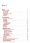
Table of Contents
Introduction.........................................................................................................................................................................4
Basic architecture...............................................................................................................................................................4
BootStrap.exe...................................................................................................................................................................4
GUIapp.exe......................................................................................................................................................................5
MediaPlayer.exe..............................................................................................................................................................5
Quitting the Application..................................................................................................................................................5
Operating system optimisations......................................................................................................................................5
Install/Upgrade process..................................................................................................................................................6
Logging system................................................................................................................................................................7
Master control file “MediaSettings.xml” and “Settings.xml”........................................................................................8
Control File linking or includes......................................................................................................................................8
Key XML Tags..................................................................................................................................................................9
<LocationName> and <ScreenName>........................................................................................................................9
<Groups>....................................................................................................................................................................9
<Interface>................................................................................................................................................................10
<Channels>...............................................................................................................................................................12
<DisplayDevices>.....................................................................................................................................................14
<AudioDevices>.......................................................................................................................................................16
<TCPIPServices>......................................................................................................................................................18
<Reboot>...................................................................................................................................................................19
<IP>...........................................................................................................................................................................20
<Logging>.................................................................................................................................................................21
<Variables>...............................................................................................................................................................23
<IPcamera>...............................................................................................................................................................24
IP camera Configurations................................................................................................................................24
<AutoSchedule>.......................................................................................................................................................26
<Security>.................................................................................................................................................................29
<IO>..........................................................................................................................................................................31
Automation and the GUI.................................................................................................................................31
<Devices>........................................................................................................................................................34
<Serial>...........................................................................................................................................................37
<IP>.................................................................................................................................................................38
<Events>..........................................................................................................................................................39
<Trigger>.........................................................................................................................................................41
Trigger syntaxEach trigger can be defined using the following process:...................................................41
Trigger types...............................................................................................................................................42
Defining a trigger messagePart of defining a trigger requires setting up how and what messages will be
sent from the dCine. The dCine allows for messages to be sent via any of the following three methods.
....................................................................................................................................................................43
<Macros>.........................................................................................................................................................46
Theatre states..............................................................................................................................................46
Macro Sytex................................................................................................................................................47
Command SyntaxA macro can be made up of two different types of commands. “Trigger” and “Sleep”.
....................................................................................................................................................................47
Error Handling............................................................................................................................................48
<DCIDevice>............................................................................................................................................................49
<MediaStore>...........................................................................................................................................................51
<Streamer>................................................................................................................................................................53
Copyright©2012 digitAll Pty Ltd
2
<WaterMark>............................................................................................................................................................54
<email>.....................................................................................................................................................................56
<Time>......................................................................................................................................................................57
Time Zone Selection...................................................................................................................................57
NTP server Selection..................................................................................................................................58
Manually Set Time......................................................................................................................................58
Auto creation of MediaSetting.xml.................................................................................................................................59
Examples............................................................................................................................................................................60
DeviceName.xml Example.............................................................................................................................................63
Copyright©2012 digitAll Pty Ltd
3
Introduction
This document covers the technical aspects of the configuration of a dCine Media Player. This
includes configuration of enterprise features and integration with other systems and technologies.
This document is for service engineers and custom installers. This document covers low level
configuration options that only a trained engineer should use or need to use. For genral operation,
please refer to the user manual.
Basic architecture
The dCine runs on windows based operating systems. It is made up of three executables.
1. Bootstrap.exe
2. GUIapp.exe
3. MediaPlayer.exe
A typical install has a hard disk with two partitions - (1) The system partition containing the
operating system, and (2) the video/data partition including the dCine software and video content
files. This partition is usually defined as drive “V” under the operating system. Having separate
system/application partitions allows for the system partition to be restored from an image/backup
without destroying the dCine install and all the media loaded onto the system.
The system will have a user called “player” with administrator privileges. This user account is set
with a password of “player” and will auto login when the system boots.
BootStrap.exe
Bootstrap is the initial process run when starting the system. It should have a link to it from the
special “startup” folder in the start menu. It will start the dCine software after auto login. This
ensures the software is started when the system is booted.
Bootstrap performs a number of setup tasks to ensure the system is operating correctly.
1. It will check to see if a more up to date release package is in the channel directory. If it finds
a newer version, it will install that version.
2. It will check the licenses and if need be, download a VPN configuration that goes with that
Copyright©2012 digitAll Pty Ltd
4
license making it show up on the support network under the correct IP and network access
permissions.
3. It will then start two processes - (1) the interface process (GUIapp.exe), and (2) the
MediaPlayer.exe process.
After it has finished, it will exit and be removed from memory. Support engineers can then upgrade
it remotely by replacing it with a new version.
GUIapp.exe
This process is used to display the control interface. When it starts, it will wait until a live control
socket to the MediaPlayer.exe is operational before loading the control. The way the interface
is displayed, screen, position etc, is controlled by the MediaSetting.xml file. Note: it is possible to
operate the software with the control hidden. This would be a more common method for a Video
out only installation with remote access only used to control the system.
MediaPlayer.exe
This is the playback engine of the MediaPlayer. It controls all playback, operates the automation
tasks and also acts as a http and ftp server.
Quitting the Application
To quit the application, you must exit both the GUIapp.exe and the MediaPlayer.exe. To do
this you need to set focus on the application you want to exit. For example, click on the video
display area (MediaPlayer.exe), then press “CONTROL-Q”. Click on the control area
(GUIapp.exe), then press “CONTROL-Q”.
Operating system optimisations
The operating system the MediaPlayer is installed on to should have a number of optimisations.
Some of these are performed by the upgrade process, but many cannot be and must be done by
hand. These include:
1. Removing the bootup graphic from the boot sequence (Adding /noguiboot to
boot.ini file)
2. Disabling the ability for switching users in the login preferences.
3. Disabling all autostart features on all drives and types. This is an important change that
Copyright©2012 digitAll Pty Ltd
5
stops many viruses.
4. Optimising the interface by: Setting the windows appearance options to basic and disabling
shadow and fade effects.
5. Many more optimisations are performed by the Install process. See Install process below.
Install/Upgrade process
When installing or upgrading the system, place an install package into the v:\channel directory.
This package will have a name similar to:
cine.20110101.rar
This file is a rar compressed collection of files that make up the install. The 20110101 portion of
the filename represents the date/version. Other text giving more detail may also be shown such as
cine.20110101.dev.rar representing a development release.
In this rar file are all the files that Bootstrap requires to install the software. One of the files is a
configuration file that manages installation of the files.
Other scripts are also run which:.
1. Check that the network devices are named correctly.
2. Check that the TAP virtual network devices exist for the support VPN link to use.
3. Disable common services not needed. This is a “very” important part of the install as it
disables “auto update” and other services that can interrupt the system. It also stops other
services that viruses could use to infect the system.
4. Sets up the firewall to be “ON” but with open ports for all services the dCine will need.
Again, this is a very important step as it protects against viruses that can travel via RPC etc.
When the BootStrap.exe is started, it will perform this install process if:
1. the dCine has not been installed previously.
2. It sees a new release cine.XXXXXXXX.rar file.
There is a script in the bin directory called “_force_reinstall.reg”. If you open this file, it
will remove the registry setting that records the information about what is currently installed.
Bootstrap will think the software has not been installed and install the cine.XXXXXXXX.rar
package it finds in the v:\channel directory. The “_force_reinstall.reg” script is
Copyright©2012 digitAll Pty Ltd
6
commonly used to force a re-install or to REVERT back to a previous version. For example, to
revert back to a previous version, remove the newer package and leave the package of the version
you want in the v:\channel directory. Run the “_force_reinstall.reg” script. Start
Bootstrap, and it will install that version.
Logging system
The dCine creates three different types of logs (a Bootstrap, Media and Operational log). For
information about configuring these logs, please refer to the <Logging> section of this document.
The log entries can be used in order to help program the string patterns which will identify
incoming messages. The logs are also invaluable if trying to problem solve a bug or other issues
with the dCine.
During installation, service engineers can monitor the logs for incoming messages from external
devices such as serial or network/socket ports. These log entries can then be used to help program
the dCine to react to an incoming message (i.e. monitor for an event which may then fire a trigger).
The Operation log can become very large. An auto delete feature will by deleting ageing files. It is
highly recommended that the logging function is always enabled.
Copyright©2012 digitAll Pty Ltd
7
Master control file “MediaSettings.xml” and “Settings.xml”
MediaSettings.xml/Settings.xmlis the root configuration file that controls all aspects of
the player. This includes how all critical aspects of the player are configured. This file is an easy to
read, XML file. It is expected support engineers will setup the more complex areas of configuration
directly in this file.
Note: The name of the control file was changed from “MediaSettings.xml” to “Settings.xml”
in versions released after Jan, 2012.
Configuration options as set out in this manual are not always required. However, a typical option
as described below should ALWAYS appear in the Setting.xml file. Otherwise unexpected
results may occur.
The Settings.xml also acts as a scripting language for setting up automation configurations.
See the Automation section for more details.
Control File linking or includes
The Settings.xml file can be split into multiple files. This allows you to create XML modules
for common configuration settings. An example of this is that we supply to partners a list of XML
files for common devices that can be automated, such as Projectors and Audio processors.
To include a XML file it is: (See the example Setting.xml file better context)
<Include>NEC_projector.xml</Include>
The NEC_projector .xml file would then contain something like the following:
<NEC_Projector>
<Display>
.
.
<Douser>
<Closed>${NecProjector} %02%16%00%00%00%18 2000</Closed>
<Open>${NecProjector} %02%17%00%00%00%19 2000</Open>
</Douser>
.
.
</Display>
</NEC_Projector>
Note: The Root tag <NEC_Projector> is ignored and can be named anything, but it is suggested
you make it the same as the file name.
The result to the MediaPlayer is a single Settings.xml file; however the Settings.xml can
be made up from a number of module XML files.
Copyright©2012 digitAll Pty Ltd
8
The most important issue to understand when using “Includes” is that certain portions of the
Settings.xml file are controlled by the interface, such as the Network Interface configuration,
the IP camera configuration and the Name and location settings.
These portions of the
Settings.xml file cannot be in an Included XML file. The MediaPlayer application cannot
update included XML files.
Key XML Tags
<LocationName> and <ScreenName>
<LocatioName> and <ScreenName> define the player variables displayed in the top right of
the GUI interface. They can be set using the interface and going to:
Buttons: Admin->System
It is important these items are set correctly as these are the descriptive names a support engineer
will use to find a system. For example, if you call a support engineer and say you are from a certain
site, he can quickly type in a search string to find your system based on these configuration options.
<Groups>
<Groups> is an option available to dCine owners who also have access to digitAll’s Virtual Private
Network. Through membership of a ‘group’ or ‘groups’ on the network, support engineers can
exercise virtual management over the dCines that belong to their business or network. The <Group>
option allows you to see whether or not you have membership of a group and, if so, which one (or
ones – a dCine can belong to multiple groups). Each group allows certain permissions of its
managers and conversely, bars others outside the group from accessing those machines. If you
require changes to your group settings, please contact the network manager. Attempted changes to
group settings by local users will be overwritten/reset by the network manager.
Copyright©2012 digitAll Pty Ltd
9
<Interface>
This portion of the Settings.xml sets up the GUI interface.
<Interface>
<Enable>Yes</Enable>
<Port>4242</Port>
<FileName>Control.swf</FileName>
<EnableGUI>Yes</EnableGUI>
<DisplayDevice>01</DisplayDevice>
<Rect>
<Left>0</Left>
<Top>96</Top>
<Width>1024</Width>
<Height>576</Height>
</Rect>
<Windows>
<Projector>10.1.1.13\\index.html</Projector>
<DCIServer>10.1.1.12\\index.html</DCIServer>
<Camera>10.1.1.19\\image.html&time=${time}</Camera>
</Windows>
</Interface>
The above options configure exactly how the GUI will appear on this control screen.
The dCine can have a touch screen or standard screen with mouse and keyboard. It is possible to
run the MediaPlayer with no GUI interface at all, for example in digital signage enviornments. A
typical cinema install would require this set of Interface configuration options.
Options:
<Enabled> : This option turns on/off the socket control port.
Values YES or NO. Default YES.
<Port> : Defines which socket/port the dCine will use for the GUI screen to communicate
with it. Default: 4242
<Filename> : This is the file name of the Adobe Flash © control application. The default
is Control.swf. This file is found in the same directory at the GUIapp.exe and
Mediaplayer.exe. Ie, “v:\channel\bin”
<EnableGUI> : This option turns on/off the GUI interface. Ie, the GUIapp.exe will not
be started. Default: YES
<DisplayDevice> : This option tells the dCine which of the configured displays should
be used to display the Control GUI. DisplayDevice is typically the first device <01>
and is defined in the MediaSetting.xml file in another area under the tag
<DisplayDevices>. Default: 01
Copyright©2012 digitAll Pty Ltd
10
<Rect> : This option defines the area of the selected <DisplayDevice> to use for the
GUI control. For example, if the <DisplayDevice> is a 1024x768 resolution display,
we can set the GUI to only use 1024x600 at position 0,0, the top portion of the display or
stretch it to the full height of the display. If the <Rect> option is absent, the GUI by
default will fill the full resolution of the <DisplayDevice>.
In order to avoid display problems, support engineers should double check to ensure that the
<DisplayDevice> option and the options under <Rect> are accurate. These control what
screen and what portion of that screen should be used to display the GUI. It can be set to utilise any
resolution and any area of that resolution. NOTE: These options are connected with the screen
resolution control options. See <DisplayDevices> below.
Copyright©2012 digitAll Pty Ltd
11
<Channels>
This section of the configuration controls the creation of the channel.
<Channels>
<01>
<Enable>Yes</Enable>
<ChannelName>Channel01</ChannelName>
<FileName>NotSet</FileName>
<DisplayDevice>02</DisplayDevice>
<Aspect>CentreCrop</Aspect>
<Rect>
<Left>0</Left>
<Top>0</Top>
<Width>1440</Width>
<Height>900</Height>
</Rect>
</01>
</Channels>
The channel is a section of the screen devoted to the playback of content/media. As part of its
digital signage functions, the dCine software can be configured to create more than one channel,
This capacity for multiple channels enables the dCine to display discreet content on different parts
of the screen or drive more then one screen from the one player.
For a typical digital cinema install, only one channel is used. The interface GUI can only control
one channel. The important options to understand in the above config set are:
<ChannelName> : This option defines which file in the “v:\channel\playlist” directory
will act as the channel event list file. For example, the default channel name is Channel01. There
will be a file called “v:\channel\playlist\Channel01.ply”. This file contains all events
that have been programmed on the player, including automation events and session-start events.
<FileName> : Deprecated. No longer used. Can be deleted.
<DisplayDevice> : This option defines which SCREEN is used as the display device. See
DisplayDevice definition below.
<Aspect> : This option sets the way the player will deal with the aspect ratios of different content.
In other words, if the content aspect ratio is wider than the aspect ratio of the display, then this
option will ensure that the player automatically readjusts for that difference. Based on this option
the player will zoom up/down the content into the viewable area.
Copyright©2012 digitAll Pty Ltd
12
The possible options are:
1. CentreCrop: This option ensures that the image fills the height of the displayable area.
However this may result in the image going outside the display area, or the appearance of
black piller boxes to each side of the image.
2. Full: The image will be made to fit the height and width of the display area. For example,
if the display area is 16:9 aspect and a 4:3 image is shown, the image will be stretched to
16:9 making the image look wider.
3. KeepAspect: This option will shrink the image and make sure the full image is viewable.
This can result in letter boxes or biller boxes, whichever ensures the full image is on screen.
4. BottomMask: Similar to KeepAspect, but will move the image to the top of the screen.
5. TopMask: Similar to KeepAspect, but will move the image to the bottom of the screen.
BottomMask and TopMask are similar to KeepAspect, but when letter box bars are present,
the black area is not set to be above and below the image. Instead, the image will be pushed to the
top or bottom of the screen.
Copyright©2012 digitAll Pty Ltd
13
<DisplayDevices>
This option defines the active screens used on the system.
<DisplayDevices>
<01>
<Enable>Yes</Enable>
<Rect>
<Left>0</Left>
<Top>0</Top>
<Width>1024</Width>
<Height>768</Height>
<Frequency>60</Frequency>
</Rect>
</01>
<02>
<Enable>Yes</Enable>
<Rect>
<Left>0</Left>
<Top>0</Top>
<Width>1440</Width>
<Height>900</Height>
<Frequency>60</Frequency>
</Rect>
</02>
</DisplayDevices>
The dCine system has two video outputs. Output 1 is for displaying the GUI screen, while Output 2
connects to the media playback screen. Output 2 would typically connect to a projector. The
DisplayDevices section of the configuration file defines the resolutions of these screens.
NOTE: When the dCine software starts, it will over-ride any modifications that have been made to
the display settings and revert to the output settings described above.
If the 3D feature is being used, a 3rd screen will be defined with the same resolution and frequency
of screen 2.
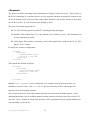
Typically the <01> screen definition is set by an engineer to best suit the GUI screen in use. The
common setting for a touchscreen is 1024x768, but any resolution/screen can be used. If support
engineers are modifying the <01> screen definition, they may also need to modify the active area
of the <Interface>. Screen <02> can be hand edited in the MediaSetting.xml file
(however it is more usual to modify screen <2> via the GUI interface).
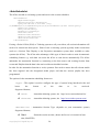
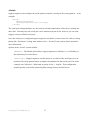
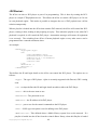
Buttons: Admin->Display
The GUI interface includes a diagram illustrating the link between screen display values and their
effects on the screen. Support engineers can use this GUI interface to assist them in configuring the
display.
Copyright©2012 digitAll Pty Ltd
14
Copyright©2012 digitAll Pty Ltd
15
<AudioDevices>
These options define how the Audio devices should be used by the dCine Media Player. A
configuration example follows:
<AudioDevice>
<Enable>Yes</Enable>
<Mode>5.1</Mode>
<SPDIF>On</SPDIF>
<Volume>90</Volume>
</AudioDevice>
These options are controlled by the GUI and are usually never edited by hand. Find the GUI page
at:
Buttons: Admin->Audio
The main Auto Devices options of interest to support engineers are the <Mode>, <SPDIF> and
<Volume>. The rest are deprecated or are reserved for internal use.
<Mode> : This option allows support engineers to configure the ways in which the dCine
will treat the audio in any media file. As an example, when “5.1” is selected, if any
“STEREO” content is played, the dCine will perform a real time mix to 5.1 before output.
This real time mixing process includes taking advantage of SR encoding if found matrixed
into a Stereo stream. If the audio is 5.1 and STEREO is configured, the dCine will mix
down the 5.1 to stereo. Other speaker set ups are also available for configuration. Based on
the speaker setup selected, the audio will be matrixed into those speakers for best possible
Copyright©2012 digitAll Pty Ltd
16
results. In general, most locations/installs have 5.1 and most content/media is 5.1 leading to
a direct pass through of the audio with no change.
<SPDIF> : This option must be turned on if SPDIF is in use, or else the system may output
incorrect audio. Typically installers use optical SPDIF; however, installers can also use coax
SPDIF by installing a coax SPDIF header cable in the dCine.
SPDIF is a domestic
implementation that can carry stereo PCM or raw AC3 data streams. (Others are possible but
the dCine only supports PCM and AC3). If the SPDIF option is off, the system will only
output stereo PCM even if an AC3(5.1) audio stream is available.
This option must be
turned on if using SPDIF; however, if this option is on when NOT using SPDIF problems
may result. Typically, the analogue output will only output in STEREO.
<Volume> : The volume option sets the master output volume of the system. It is
recommended that cinemas with external sound processors set the dCine volume option to
95%. The dCine can then be programmed with automation commands to control sound
through the external sound processor. The dCine real time GAIN feature can be used to
ensure best possible results from any audio stream. Master Volume can be controlled by
automation; however the original purpose of the Master Volume option was for digital
signage type applications where the player acted as the audio processor.
Copyright©2012 digitAll Pty Ltd
17
<TCPIPServices>
This option is used to setup the internal HTTP and FTP servers built into the dCine:
<TCPICServices>
<Http>
<Enable>Yes</Enable>
<Port>80</Port>
<Directory>..\</Directory>
</Http>
<FTP>
<Enable>Yes</Enable>
<Port>21</Port>
<Directory>..\</Directory>
</FTP>
</TCPICServices>
The dCine has a built in Web server and FTP server. These services are integral to certain
functionings of the dCine. Typically, the <TCPIPServices> options should always be present
in the Settings.xml file and configured as shown above. Disabling or changing them in any
way is likely to break functionality.
The HTTP server is needed to allow Web remote control of the dCine. This includes the Flash ©
based remote interface and the dUsher for mobile devices/phone.
The FTP server allows the movement of media files in and out of the dCine over a network. It is
also commonly used to upload upgrades.
Copyright©2012 digitAll Pty Ltd
18
<Reboot>
The Reboot option sets up the system to reboot itself nightly:
<Reboot>
<Enable>No</Enable>
<Time>00:00</Time>
</Reboot>
This option is usually set up using the GUI. It is found on the screen:
Buttons: Admin->System
If a system is left on 24 hours a day over prolonged periods, it is recommended that you set up the
nightly reboot function. A reboot will refresh the memory subsystem and ensure performance
issues do not develop.
This reboot function is primarily for digital signage applications because such sites are usually left
to operate with no human intervention or power cycles.
Copyright©2012 digitAll Pty Ltd
19
<IP>
This option sets up the Network Interface on the dCine:
<IP>
<EnableDHCP>No</EnableDHCP>
<Address>10.30.100.160</Address>
<SubMask>255.255.255.0</SubMask>
<Gateway>10.30.100.5</Gateway>
<DNSAutoEnable>No</DNSAutoEnable>
<DNSAddress>10.11.1.2</DNSAddress>
</IP>
This configuration can be modified via the GUI:
Buttons: Admin->System
The top right portion of the screen will show the IP configuration. Clicking on the Change button
allows the user to edit the values.
It is important that the dCine be connected to the internet with the correct network configuration so
that remote users can access the system. Remote support engineers can then access the dCine via
the Web for monitoring, network ingest and Network based automation purposes.
The correct network configuration is also required for the VPN to connect to the digitAll support
network. The network requires that the dCine have access to the internet in order for the VPN to
work. For this reason, it is important that the IP address, gateway and DNS be set up correctly.
Typically many installers leave the configuration on DHCP. The DHCP configuration enables the
dCine to select the correct setting from the Internet DSL modem or similar device.
However, it is possible that the IP address can change between reboots when using DHCP. STATIC
configuration is best (setting by hand) if you are likely to be effected by IP address changes.
A dCine can have more then one network interface installed. In order to nominate which interface
the dCine GUI controls, the desired network interface must be allocated a specific name.
“digitAll – MediaPlayer”
When the BootStrap.exe runs and discovers a new install, it will run a script to ensure an
interface exists with this name. It will look for the most likely interface and rename it.
If <EnableDHCP> is YES, the <Address>, <Netmask> and <Gateway> options are ignored.
If <DNSAutoEnabled> is YES, <DNSAddress> is ignored.
<Address>, <Netmask>, <Gateway> and <DNSAddress> are as named.
Copyright©2012 digitAll Pty Ltd
20
<Logging>
The dCine logs many aspects of its operations. The Logging option allows you to configure where
log files will be stored on the hard drive and how often they will be deleted. As an example:
<Logging>
<Media>
<File>
<Enable>Yes</Enable>
<Filename>..\log\Media_</Filename>
<Dated>Yes</Dated>
<MaxDayLog>365</MaxDayLog>
</File>
</Media>
<Operations>
<File>
<Enable>Yes</Enable>
<Filename>..\log\Oper_</Filename>
<Dated>Yes</Dated>
<MaxDayLog>90</MaxDayLog>
</File>
</Operations>
</Logging>
Logging is an important feature. Apart from keeping track of when media is played, it also keeps
track of many low level events. Such a feature is important when trying to work out bugs or the
causes of other issues or problems that may relate to operator error, communication failure, etc.
The d-Cine creates two types of log files – the Media log and the Operation log. The <Media> log
keeps track of when media files are played. The <Operations> log keeps track of low level data
used for debugging and GUI interface operations tracking (i.e. what button was pressed by an
operator and when.) The Media and Operations log files can be turned off but typically should not
be.
The XML configurations outlined above are self explanatory. What follows is a description of the
Media and Operations log options.
<Enable> : Enable is used to turn on/off the logging feature. Default: YES
<Filename> : The Filename option contains the file name, including path, to the relevant log file.
The default setting for this option is “..\log\LogType_”. This setting indicates where the log
files should be created, based on the location of the MediaPlayer.exe executable. The “..”
indicates that support engineers can find the log file by moving into the parent directory above the
directory where MediaPlayer.exe lives (usually the bin directory), then clicking into the
“log” directory. A file is created called “logtype_XXXXXXXX.log” where XXXXXXXX is
the current date added to the end of the ”LogType_” filename.
Copyright©2012 digitAll Pty Ltd
21
<Dated> : The Dated option makes a new file per day with an extension representing that date. If
not configured, the Dated option keeps adding to the named file.
<MaxDayLog> : MaxDayLog allows support engineers to stipulate the maximum number of days
that the log history will keep. If a log file is older then MaxDayLog in days, it will be deleted
automatically.
Copyright©2012 digitAll Pty Ltd
22
<Variables>
Variables are used to help configure automation scripting:
<Variables>
<PioneerSerial>COM3,9600,N,8,1</PioneerSerial>
<AP20>IP:10.30.100.165:14500</AP20>
<JNIOR>IP:10.30.100.14:9200</JNIOR>
</Variables>
Variables are used in the XML configuration files to help set up device control. For example, in the
above example, the variable name “AP20” is defined as “IP:10.30.100.165:14500”. Any
appearance of the variable name in the form of ${AP20} in an XML configuration file, will be
replaced with the string: “IP:10.30.100.165:14500”
In order to demonstrate this for readers, the following is taken from the Datasat_AP20.xml
module used as an <Include> for controlling the Datasat AP20 cinema audio processor:
<Power>
<On>${AP20} PO%0d</On>
<Off>${AP20} PF%0d</off>
</Power>
As the variable ${AP20} is defined as “IP:10.30.100.165:14500”, the dCine will actually
see the automation command string as:
<Power>
<On>IP:10.30.100.165:14500 PO%0d</On>
<Off>IP:10.30.100.165:14500 PF%0d</off>
</Power>
This allows the Datasat_AP20.xml module to refer to a variable for the communications
address (i.e. the IP address and port number that the dCine will connect to). The use of variables has
a number of advantages. First, it enables support engineers to change all the automation commands
by modifying just that single variable. Further, it allows for the implementation of a control module
by using the <Include> option for that module.
Support engineers are encouraged to try and utilise the modules as are. However the modules can be
customised to suit.
Copyright©2012 digitAll Pty Ltd
23
<IPcamera>
For a real time feed of what is going on in the cinema, we ustilise IP cameras:
<IPcamera>
<Enable>off</Enable>
<Type>VIVOTEK</Type>
<Delay>1000</Delay>
<IP>10.30.1.17</IP>
<Offset>0</Offset>
<Width>320</Width>
<Height>240</Height>
<HeightOffset>0</HeightOffset>
</IPcamera>
These options are typically configured in the GUI:
Buttons: Admin->System->IPcamera config
An important feature of the dCine is the ability to add a live feed of an IP or network camera to the
interface. This is especially important if controlling the system from a remote location. If a
location based problem occurs, such as lights not working, masking not working, or projector
colour spacing being wrong, an agent at the remote location can actually see what is going on.
When cinema goers are left wondering what is going wrong the ability for the remote support agent
to see what is happening makes it far more likely the session can get to screen even after a problem.
The dCine supports cameras with the ability to send jpeg stills via http requests. The dCine will
pull a still image from the camera at set intervals defined by the <Delay> option.
The <Type> option defines the type of camera used. It also defines the URL used to retrieve the
jpeg still from the camera. (Note: This option will be replaced in future releases. Currently only a
small number of cameras are supported by the dCine software. It is anticipated that the URL will be
made configurable so as to support any camera.
<IP> The IP option defines the IP address of the camera.
<Offset>, <Width>, <Height> and <HeightOffset> These options allow support engineers to define
the image size that it is expected will be delivered from the camera. It also allows for the
configuration of an offset to move an image in the viewable area.
If this option is disabled, the dCine will fall back to displaying a proxy grab of the current playing
item if available.
IP camera Configurations
It is important to configure the IP camera to produce low resolution, highly compressed stills. If the
Copyright©2012 digitAll Pty Ltd
24
monitoring agent is retrieving images frequently this can add significant load to the network. It is
recommended that the IP camera be set to as low a quality and resolution that is acceptable. This
will reduce any potential load on the network, which is especially important when monitoring the
system over a WAN (Wide area network) ie a remote location.
A common setting would be 320x240 resolution images at 50% quality. It is also recommended to
reduce the internal camera frame rate to 1-3fps. Disable any audio features if present.
Copyright©2012 digitAll Pty Ltd
25
<AutoSchedule>
The dCine can talk to a ticketing system and retrieve the session schedules:
<AutoSchedule>
<Type>Venue</Type>
<Automation>Start</Automation>
<Query>IP:192.168.0.107:4016 {vrq}
{1}HOBART{2}0{3}2{4}MediaPlayer{5}3{8}101379432241!{1}4%03 10000</Query>
<OnInit>no</OnInit>
<Daily>04:28</Daily>
<NoOfDays>7</NoOfDays>
<Vars>Yes</Vars>
<Verbose>true</Verbose>
<PreStart>120</PreStart>
<Preload>60</Preload>
</AutoSchedule>
If using a Point Of Sale (POS) or Ticketing system to sell your tickets, all session information will
need to be entered into that system. Point of sale or ticketing systems typically make session data
(such as a Session Time Display or the Projection automation system data) available to other
systems (the dCine). The dCine takes advantage of this type of data in order to assist its automatic
scheduling features e.g. such data can assist the dCine to start shows automatically. The dCine
undertakes the automation function by connecting to the data source and creating Session Start
events and Playlists that the data it has retrieved about scheduled sessions.
In order for the automation function to work, operators first need to ensure that all relevant media
has been ingested into the designated media player and that the session playlist has been
programmed.
The options for the automation scheduling feature are:
<Type> : This option is used to configure the type of system being interfaced with, and
hence
the
format
of
the
data
to
be
retrieved.
Supported formats;
Venue
- Australian ticketing system, site http://www.venuesolutions.biz/
Showcase
- Australian ticketing system, site http://www.ticket-systems.com/
<Automation> : Automation Session Type (depends on your automation system)
Supported formats;
Start
- Starts the session on time, (hence the Server is in control of start
time, MASTER)
Copyright©2012 digitAll Pty Ltd
26
Prepare
- Prepares the session by loading but not starting it at the scheduled
time. It is expected an external device, such as an older Automation system, would
trigger the start of the session. (hence the Server is a SLAVE)
<Query> : The Query option enables support engineers to formulate requests for data
from the Point of sale system. To retrieve such data, support engineers need to specify
particular information regarding the location in their query.
Supported formats for the Query option;
IP:XX.XX.XX.XX:Port URLEncodedString [timeout]
Note: See IP Trigger programming information
ftp://username:[email protected]/directory/file
Note: Username & password is optional
<OnInit> : (optional) Support engineers should select either Yes or No for this option. If
the option is set to Yes, your dCine will run the AutoSchedule process on start up.
<Daily> : (optional) Support engineers can use the Daily option to set the time of day they
wish the dCine to contact the Ticketing system for retrieval of the POS data. The dCine will
use this data to update events.
Format HH:MM, eg. 07:00.
Note: Do not use the Daily option in circumstances where a session may be running
as it will interrupt that session.
<Weekly> : (optional) This option operates similarly to the Daily option, except it allows
for the scheduling of data retrieval on a weekly basis.
Format DayOrWeek HH:MM, eg. Monday 07:00
<NoOfDays> : (optional) This option allows the support engineer to nominate a set of
limits around the POS data that the dCine processes.
Format: Num, eg. 7 (seven days/1 week in advance)
<Vars> : Use the Variables option to create a file containing variables that can be used by a
Session information system in order to undertake its functions (e.g. display session times).
Copyright©2012 digitAll Pty Ltd
27
Copyright©2012 digitAll Pty Ltd
28
<Security>
The dCine interface implements security access layer: expression? Singular?
<Security>
<WebAccess>Off</WebAccess>
<Console>Off</Console>
<Monitor>
<Access>monitor</Access>
<Password>81dc9bdb52d04dc20036dbd8313ed055</Password>
</Monitor>
<Operator>
<Access>operator</Access>
<Password>81dc9bdb52d04dc20036dbd8313ed055</Password>
</Operator>
<Editor>
<Access>editor</Access>
<Password>81dc9bdb52d04dc20036dbd8313ed055</Password>
</Editor>
<Admin>
<Access>admin</Access>
<Password>81dc9bdb52d04dc20036dbd8313ed055</Password>
</Admin>
<Tech>
<Access>tech</Access>
<Password>81dc9bdb52d04dc20036dbd8313ed055</Password>
</Tech>
</Security>
Security can limit access by users, either via the Web or Machine Console/GUI
Access Levels are listed below:
montior
- can only watch machine operations
operator
- can control playback and automation functions
editor
- can add/delete content, and create playlists
- can change machine name, TCPIP, projector resolution, audio, view logs,
admin
edit users
tech
- can access automation programming etc.
The following code provides an example of the way in which a user and the user’s level of security
can be defined in the Settings.xml file.
Format:
<UserName>
<Access>monitor</Access>
<Password>81dc9bdb52d04dc20036dbd8313ed055</Password>
Copyright©2012 digitAll Pty Ltd
29
</UserName>
The Default MediaSetting.xml file contains an example configuration for security access. In
the example above, the security settings are disabled. If turned on by modifying the
<Webaccess> or <Console> values to true, the users defined below these options will be
active. All user passwords will be '1234'
Copyright©2012 digitAll Pty Ltd
30
<IO>
This portion of the MediaSetting.xml file is used to set up all the automation messages
coming into and out of the dCine. Based on these messages, the dCine can perform as a fully
featured Automation system.
Configuring the IO section for automation requires a number of steps. These steps include having
the support engineer
•
Set up relevant devices for the dCine to monitor, such as serial ports, sockets and contact
closure units;
•
Define “string patterns” that the dCine will monitor for on configured devices. Each string
pattern is allocated a specific name denoted as an event.
•
Define <Triggers> (for example “Door Open”) and how the dCine needs to communicate
this trigger out through a configured IO device;
•
Define <Macros> (Macros describe a group of Triggers).
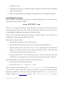
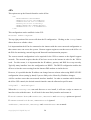
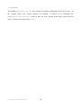
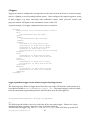
Automation and the GUI
Once configured, all events and triggers are programmable via the GUI. You can set up an
<Event> to trigger anything from starting a show to triggering a device or a <Macro>. A playlist
can be programmed to trigger any device at any stage of the session.
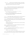
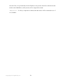
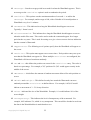
With the GUI Automation control screen, you can send a trigger to any device.
Copyright©2012 digitAll Pty Ltd
31
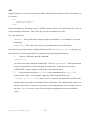
The Automation Control screen seen in the above diagram is split into 4 sections;
Auditorium : These are external triggers that effect the theatre, such as lights, masking
and doors.
Audio : These are controls that effect the audio processor, such as the volume, mute and
input selections.
Display : These are external triggers that effect the display or projector.
Theatre State : This section of the automation screen is made up of one button only. It
shows the <Macro>s that can be run. Please see the Macro Section for more information.
List All is a debug tool used by support engineers to find problems in the automation
configuration.
Lamp Hours is deprecated and will be removed in future releases.
The automation GUI remembers the last known state of a trigger device, e.g. Lights:UP indicates
that the lighting system was last sent the “UP” message. This helps support engineers to debug the
automation system by making clear to the engineer that a message has been sent, even if a resulting
action on the dCine has not occurred. For example, if the automation GUI screen says lights should
be down but you observe they are still up, you can deduce that the message was lost if you have
evidence that the automation did trigger the event.
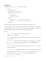
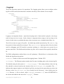
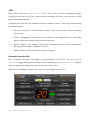
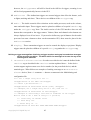
The automation trigger list also contains a special “List All” button that is used to debug all
automation triggers.
Copyright©2012 digitAll Pty Ltd
32
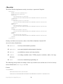
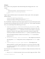
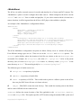
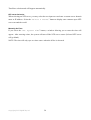
You can use the List All button to search for a defined Trigger. After pressing List All you
will see the “Trigger Type:” and the “Trigger Name:”. This tells you how the trigger will
appear on the automation button screen. The “Args:” section describes exactly what the trigger
will do. The above diagram includes an example for the “Args:” for Lights:UP “Device 00 Pulse PIN:3 On 1000”
In the above example, the “Lights:UP” trigger is programmed to send a message to a hypothetical
contact closure unit configured as device 0. This unit is sent a message to pulse pin 3 to the On
state for 1000 milliseconds (1 second). Having the capacity to see the command as it will eventuate
is useful for debugging purposes; this is because it takes into account the ${VARIABLENAME}
used to generate the commands. Support engineers can visually check what the result expressions
are and select and test the messages going out.
Copyright©2012 digitAll Pty Ltd
33
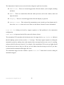
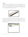
<Devices>
IO-Contact-Closure devices are defined in the Devices section. An IO-Contact-Closure device is
typically used to talk to traditional cinema systems such as lights, masking and doors. These
cinema systems are usually controlled through an automation process that simulates buttons being
pressed i.e. a contact coming together to make a circuit. The dCine uses industrial strength USB
devices from Measurement Computing to perform these tasks.
Support engineers should install the relevant driver for the Measurement Computing unit. The
driver should be installed by default on a dCine, however the driver installer can also be
downloaded from the digitAll website. Once the driver is installed and the device has been
connected, support engineers will need to detect the device using a utility that comes with the driver
installer called InstaCal.
Copyright©2012 digitAll Pty Ltd
34
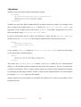
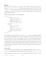
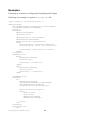
Once the device has been detected by the Instacal utility, it will be allocated a device number,
(usually “00”). The device type will also be displayed. (See image above) The device number and
type are needed when setting up devices in the MediaSetting.xml file.
It is highly
recommended that support engineers perform diagnostic tests during the installation process. Note:
you can use the InstaCal tool at any time to run diagnostic tests on the device.
The list of device types that are compatible with the dCine software are:
USB_ERB08 : 8 port output device
USB_ERB24 : 24 port output device
USB_SSR24 : 24 port in or output solid state device (Has the red light indicators)
An example follows:
<Devices>
<00>
<Enable>Yes</Enable>
<Type>USB_SSR24</Type>
<ID>00</ID>
<IO>OOOOOOOOOOOOOOOOOOOOIIII</IO>
</00>
</Devices>
The options in the Devices section perform the following functions:
<Enable> : This option allows you to Enable(Yes) or Disable(No) the device.
<Type> : The type option allows you to set the type of device the dCine will be
communicating with. This value will have been made available through the InstaCal
tool when the device was installed.
<ID> : The <ID> is the number allocated to the device when it is detected by the InstaCal
tool during the installation process. “00” is generally allocated to the first device. You can
install up to 256 devices, (although one is usually enough).
<IO> : This section defines the terminal type on the IO-contact-closure device. Devices of
type USB_ERB08 and USB_ERB24 have only output terminals. The USB_SSR24 device
can also accept input signals. The following string of ‘O’s and ‘I’s represent which which
terminals on the device are “I” inputs or “O” outputs. Typically the 8 input device
Copyright©2012 digitAll Pty Ltd
35
USB_ERB08 would be <IO>OOOOOOOO</IO> and the 24 port unit USB_ERB24 would
be <IO>OOOOOOOOOOOOOOOOOOOOOOOO</IO>.
The USB_SSR24 device can also have inputs. In the above example,
<IO>OOOOOOOOOOOOOOOOOOOOIIII</IO>, the last 4 terminals have been set up to
act as Inputs.
Once the IO device is configured, you can set up <Event> to listen for an input on an ‘I’ (input)
terminal or set a <Trigger> to send a message out an ‘O’ (output) terminal.
Note: all activity on the IO-contact-Closure device is logged into the operational log. If a problem
taking to the device occurs, or an error is detected in the device, the log entry should indicate this.
Copyright©2012 digitAll Pty Ltd
36
<Serial>
Support engineers can configure the serial option to monitor a serial port for a string pattern. As an
example;
<Serial>
<Enable>Yes</Enable>
<Settings>COM1,9600,N,8,1</Settings>
</Serial>
The serial port settings/attributes are also set here and must match those of the device sending the
data. Note: Currently only one serial port can be monitored by the dCine, however you can send
triggers out any available serial ports.
Once the serial port is configured support engineers can define events to listen for, such as a string
pattern like “FireAlarm” coming from another device. See the Events section of this manual for
more information.
Options in the <Serial> section include;
<Enable> : The Enable option allows support engineers to Enable(Yes) or Disable(No)
the monitoring of a serial device.
<Settings> : Support engineers use this option to set which of the serial ports is to be
monitored for string patterns and to configure the attributes for that serial port. The earlier
example sets COM port 1, 9600 baud, no parity, 8 bits , 1 stop bit. This configuration
should typically work when monitoring data coming from an external device.
Copyright©2012 digitAll Pty Ltd
37
<IP>
Support engineers can use the IP option to define what network socket the dCine will monitor. As
an example;
<IP>
<Enable>Yes</Enable>
<Port>4241</Port>
</IP>
When monitoring for incoming events, a TCP/IP network socket on the dCine must be set up to
accept incoming connections. Note: Only one port can be monitored at a time.
The <IP> options are;
<Enable> : This option allows support engineers to Enable(Yes) or Disable(No) the port
monitoring.
<Settings> : This value is the socket or port number the dCine will monitor.
Once network port monitoring is configured and the dCine MediaPlayer.exe is running, you
may check to see if the port specified is working correctly by doing the following;
1.
Under a CMD shell, enter the command;
> netstat -a
You will see the port configured, default 4242, listed as “LISTENING”. This indicates that
dCine has opened the port and is listening for connections. If the port is not listed as
“LISTENING”, support engineers will need to investigate the issue.
2.
Using a telnet tool such as “telnet” in the command shell or “putty.exe”,
connect to the socket. As an example, under the CMD command shell, enter;
> telnet 127.0.0.1 4242, where 127.0.0.1 is the local loopback IP, and 4242 is the
default socket port number for which the dCine is listening. This command will connect you
directly to the socket. From here you can type in the string patterns you are testing. You can
also type “HELP” to receive a list of events and the string patterns associated with those
events.
Copyright©2012 digitAll Pty Ltd
38
<Events>
Here we define events, giving them a name and describing what will trigger that event. As an
example;
<Events>
<SerialStart>Serial %7e%07%05%47%02%01%ff</SerialStart>
<SocketStart>Socket Start</SocketStart>
<IOstart>Device 00 Pin:21 High</IOstart>
</Events>
Support engineers define the names of events under the <Events> option. Such events might be
defined as follows;
<UserDefined>InputType</UserDefined>
<EventSerial>Serial URLEncodedString</EventSerial>
<EventIP>IP URLEncodedString</EventSerial>
<EventKeyboard>Keyboard URLEncodedString</EventKeyboard>
The <UserDefined> configuration option allows support engineers to specify which input the dCine
will monitor and the string pattern that will fire the relevant event. In the example immediately
above, we are monitoring for three different types of events.
1. <SerialStart>Serial %7e%07%05%47%02%01%ff</SerialStart> : This
configured event monitors for a string pattern of non printable Hex characters on the serial
port as configured in the <Serial> option above. For the current example we expect nonprintable hex characters. The support engineer specifies these characters using the URL
encoded representations of the characters; that is, a “%” symbol is used followed by the Hex
value representing the character as shown in an ascii table (e.g. “%7e” is a hex character
with the value 7e).
2. <SocketStart>Socket Start</SocketStart> : This configured event listens for
the string pattern “start” coming into the socket as configured in the <Socket> option
above.
3. <IOstart>Device 00 Pin:21 High</IOstart> : This configured event
monitors terminal 21 on an IO-Contact-Closure device to see if it moves from low to high,
for example in circumstances where a pushed button or a Master automation system send a
message to the dCine.
Once Events have been configured, there are two methods to configure what actions will arise from
these events;
1. Set up a <Macro> with the same name as the event you wish to trigger your Macro. When
Copyright©2012 digitAll Pty Ltd
39
an event fires and the event name is the same as the macro name, this will make that macro
fire.
2. Set up an event to listen for in the “Events” section of the GUI interface. In order to define
an event, go to;
Buttons:Events->New,
Then Buttons:Edit, Then Buttons:Type
Select “Input From IO” and then select the button beneath “Type” to list the
configured events. From the window which pops up in this section, select the event to listen
for. Use the buttons on the right hand side of the screen to select the ACTION to perform
when the event fires. Please see the operational manual for more information.
Copyright©2012 digitAll Pty Ltd
40
<Trigger>
Triggers are used to configure the messages that can be sent out from the dCine to external systems,
such as a lighting or screen masking/curtain system. Once configured by support engineers, many
of these triggers (e.g. those associated with auditorium control, audio processor control, and
projector control) will appear in the automation section of the GUI.
A typical example of a trigger configuration has been set out below.
<Trigger>
<CueOut>Serial %6f%07%05%47%20%83%ff</CueOut>
<Proj>
<Include>PJLink.xml</Include>
</Proj>
<Audio>
<Include>Pioneer.xml</Include>
</Audio>
<Lights>
<Off>Device 00 Pulse Pin:0</Off>
<Prg1>Device 00 Pulse Pin:1</Prg1>
<Prg2>Device 00 Pulse Pin:2</Prg2>
<Up>Device 00 Pulse Pin:3</Up>
<Cleaning>Device 00 Pulse Pin:4</Cleaning>
</Lights>
<Door>
<Open>Device 00 Pulse Pin:5</Open>
<Close>Device 00 Pulse Pin:6</Close>
</Door>
<Curtains>
<Open>Device 00 Pulse Pin:7</Open>
<Close>Device 00 Pulse Pin:8</Close>
</Curtains>
<Masking>
<Scope>Device 00 Pulse Pin:9</Scope>
<Wide>Device 00 Pulse Pin:10</Wide>
</Masking>
</Trigger>
Trigger syntaxEach trigger can be defined using the following process:
(i)
The following entry defines a trigger that will not show up on the GUI interface with a button as it
is not defined within a <DeviceNameToTrigger> tag. This named trigger is still accessible
from the automation programming interface and will show up in the full trigger list..
<TriggerName>MessageChannel Message</TriggerName>
(ii)
The following code defines a device to which the dCine can send a trigger. That device is then
configured to have a number of possible states as defined within the
<DeviceNameToTrigger> tag. The DeviceNameToTrigger name will show up on the GUI
Copyright©2012 digitAll Pty Ltd
41
automation screen indicating what state was last sent to that device
. For example “DeviceNameToTrigger:State1ForDeviceName”
When a DeviceNameToTrigger button is pressed, a new window showing all the possible
StateXForDeviceName configured within the <DeviceNameToTrigger> tag will be
shown.As this Device is not defined under the <proj> or <Audio> tag, the button will appear in
the Auditorium section of the Automation GUI.
<DeviceNameToTrigger>
<State1ForDeviceName>MessageChannel Message</State1ForDeviceName>
<State2ForDeviceName>MessageChannel Message</State2ForDeviceName>
.
.
<DeviceNameToTrigger>
.
.
In the following example, the <DeviceNameToTrigger> is nested in a special tag of <Proj>
or <Audio>. If a <DeviceNameToTrigger> is
placed within <Proj>, these DeviceNameToTrigger buttons will appear under the
Display/Projector section of the Automation GUI. If a <DeviceNameToTrigger> is placed
under the <Audio> tag, it is placed under the Audio section of the Automation GUI. Under the
Audio section of the GUI interface, the buttons will not appear. Only have Volume level and audiochannel select buttons are shown. These are hard coded buttons and cannot be changed.
<Proj>
<DeviceNameToTrigger>
<State1ForDeviceName>MessageChannel Message</State1ForDeviceName>
<State2ForDeviceName>MessageChannel Message</State2ForDeviceName>
.
.
<DeviceNameToTrigger>
</Proj>
In this example, we define the <Audio> section of the automation. However, in this case we are
including an external XML template for the Datasat AP20 sound processor. A list of template files
are available from digitAll for common audio processors. See the manual above on using the
<Include> tag.
<Audio>
<Include>Datasat_AP20.xml</Include>
</Audio>
Trigger types
The <Trigger> configuration option is split into 4 areas. Depending on the Trigger type, these
options must be placed in different areas under the <Trigger> section of the Settings.xml
file;
Button Not Displayed : If a trigger message is defined but it is not the child of a
DeviceNameToTrigger, it will not be displayed on the Automation Button GUI.;
Copyright©2012 digitAll Pty Ltd
42
however, the TriggerName will still be listed in the full list of triggers, meaning it can
still be fired programatically, but not via the GUI.
Auditorium : The Auditorium triggers are external triggers that effect the theatre, such
as lights, masking and doors. These devices are children of the <Trigger> tag.
Audio : The Audio controls effect selections on the audio processor, such as the volume,
mute and audio-input. These triggers must be placed as children of a special <Audio> tag
under the <Trigger> tag. Note: The Audio section of the GUI interface does not add
buttons that correspond to the trigger names. Volume, Mute and channel-select buttons are
always displayed even if not in use. If you need to define any special buttons for the audio
processor but want a button to show on the automation GUI, these must be placed in the
Auditorium section.
Display : These automation triggers are used to control the display or projector. Display
triggers must be placed as children of a special <Proj> tag under the <Trigger> tag.
Defining a trigger messagePart of defining a trigger requires setting up how and what messages
will be sent from the dCine. The dCine allows for messages to be sent via any of the
following three methods.
1. IO-Contact-Closure Devices: In order to use this device it must be defined in the
<Device> tag as described in the <Device> section explained above. In the device
section support engineers must set a device number (for the prescribed device) and the
terminal types. What follows are examples of sending a message to an IO-ContactClosure device; Note: <!--comment --> denotes a comment in the MediaSetting.xml
configuration file.
<!-- Set a single relay ON or Off -->
<Trigger>Device 00 Set PIN:5 On</Trigger>
<!-- Pulse a pin definition -->
<Trigger>Device No Pulse PIN:X On/Off [time] </Trigger>
<!-- Example, Set a single relay ON for 1 sec, then off -->
<Trigger>Device 00 Pulse PIN:5 On 1000</Trigger>
<!-- Example of controlling a full bank of terminals in one trigger
This is used to set a bank on relays to a position;
X - leave relay in current state.
0 - Turn relay off.
1- Turns relay on. -->
<Trigger>Device No X000 X111 XXXX XXXX XXXX XXXX</Trigger>
Copyright©2012 digitAll Pty Ltd
43
2. Internet Socket: The dCine can talk to an unlimited number of internet sockets. In
the trigger definition, you can refer to any IP:Socket address. See, for instance, the
following example:
<!--IP trigger definition -->
<Trigger>IP:XX.XX.XX.XX,Port=XX,ConnectTimeout=XX URLEncodedString
Timeout=XX</Trigger>
<! example of talking to a Web server to send a message follows -->
<Door>IP:10.1.1.1,Port=80,ConnectionTimeout=500 GET+%2Fstate.xml
%3FrelayState%3D2+HTTP%2F1.1%0d%0a%0d%0a Timeout=1000</Door>
Socket based triggers have become a common method for automation messaging. With
socket based messaging, you can connect to any device that exposes a socket and send a
string pattern message into that device. Note: Socket based triggers do not support handshake based messaging, such as a login process, and therefore such messaging is not
recommended. Further, due to the tendency for protocols to change over upgrades, problems
are likely to occur. Non-handshake type messaging is more likely to work with more
devices and should require less maintenance..However if a handshake type protocol is
desired/required, a device driver specific to the protocol used would need to be
implemented..
If there are any problems or faults when using socket based messaging, these will be
reflected in the operational log..
3. Serial: Serial based messaging is most commonly used to communicate with older
devices such as Audio players (CD-players, DAT-players). The dCine can send messages
via all of its installed serial ports but can only listen to one of these serial ports. Serial ports
must be specified in the <IO> section in order to monitor for messages.(Please see the <IO>
section on this manual)
Note the following example of a serial based messaging configuration:
<!--Serial definition -->
<Trigger>Serial URLEncodedString</Trigger>
<!-- Example sending a message out of the serial port being monitored -->
<Trigger>Serial LightsOff</Trigger>
<!-- definition of sending a message out any connected COM port -->
<Trigger>COMX,Baud,d,p,s
URLEncodedString [timout]</Trigger>
<!-- example sending a message “LightsOff” out COM3 -->
<Trigger>COM3,9600,8,n,1 LightsOff</Trigger>
Copyright©2012 digitAll Pty Ltd
44
Copyright©2012 digitAll Pty Ltd
45
<Macros>
Macros are used to tie together a set of triggers. This is useful for defining a single button to
represent a “Theatre
State”. A scripting type language within the XML text of the
Settings.xml file is used to tie together a set of triggers..A Macro can be fired in the same way
a <Trigger> is used, .however in the case of macros, one trigger message will encapsulate all the
triggers defined in the macro.
Note the following example of a macro configuration:
<Macros>
<PreSession>
Trigger Lights:House
Trigger Audio:Volume:50
Trigger Audio:Input:NonSync
Trigger Door:Open
Trigger Curtains:Closed
Trigger Proj:Douser:Closed
Trigger Proj:Input:eCinema
</PreSession>
<PreShow>
Trigger Curtains:Open
Sleep 5.0
Trigger Lights:Prog1
Sleep 5.0
Trigger Audio:Input:eCinema
Trigger Audio:Volume:70
Trigger Proj:Macro:eCinema
Trigger Proj:Douser:Open
</PreShow>
</Macros>
In the example above, support engineers can use the <Macros> option as a convenient method for
setting up all devices/equipment into the correct configuration for a particular environment. In the
above example there is a macro called <PreShow>. This macro will send all Trigger messages
required to configure the theatre for the PreShow portion of a session. The macros feature is
especially important in more complex sites that may receive feeds from a plethora of sources such
as a DCI-player, an eCinema-player, a BluRay-player, a Satellite box, a Terrestial-TV-box etc. Each
video source requires that multiple devices are specifically configured for the selected video device
to work correctly.
Theatre states
As macros help with setting up the state of all the equipment and theatre, the idea of “Theatre
States” is used in the interface to represent this to the GUI. The heading “Theatre State” is
shown in the middle top section of the “AutoM” automation GUI section of the interface.,. Under
Copyright©2012 digitAll Pty Ltd
46
the heading “Theatrre State” a button showing the last activated Macro used. Selecting this button
will list all programmed macros for selection by the dCine operator giving him maual control .The
top-middle of the GUI displays “TheaterState:” and is shown at all times so the operator can
see the last macro used on the GUI. This enables the operator to understand at a glance how the
system is configured.
Macro Sytex
The syntax of a macro is reflected in the following example:
<Macros>
<MacroName>
Command
Command
.
.
</MacroName>
</Macros>
Command SyntaxA macro can be made up of two different types of commands. “Trigger” and
“Sleep”.
The trigger command is followed by a Trigger definition. Example;
<!-- Trigger auditorium lights to UP -->
Trigger Lights:UP
<!-- Trigger Audio volume -->
Trigger Audio:Volume:50
<!-- sleep X seconds before sending the next trigger →
Sleep 1.5
To understand what the trigger syntax should be, see this example;
<!-- See this Trigger definition -->
<Trigger>
<Lights>
<UP>Device 00 Pulse Pin:3</UP>
</Lights>
</Trigger>
<!-- to refer to this trigger, the Macro trigger command must be →
Trigger Lights:UP
In the above example, the trigger command refers to the XML tags with a “:” character between the
levels, finishing with the level where the actual trigger message is defined.
Copyright©2012 digitAll Pty Ltd
47
Error Handling
If your Macros refer to a non existent trigger, an error message will appear in the Operation Log
when the trigger attempts to fire that command.
Copyright©2012 digitAll Pty Ltd
48
<DCIDevice>
The dCine can slave a DCI-player as part of its programming. This is done by treating the DCIplayer as a simple VTR/playback device. This allows the dCine to control a DCI player as if it was
its own playback engine. This makes it possible to integrate the use of DCI payback into a dCine
solution transparently.
When a playlist is loaded into the dCine that contains DCI material, the dCine will control the DCIplayer, creating a show, loading it and preparing it to play. Then when the playlist is run, when DCI
playback is required, it will control the DCI-player. Automation messages will ensure all equipment
is set correctly. The switching from dCine eCinema playback engine or any other source can be
programmed into a smooth continuous show.
An example:
<DCIDevice>
<Type>Qube</Type>
<IP>
<User>QubeAdmin</User>
<Password>ararat</Password>
<Address>10.30.7.11</Address>
<Port>80</Port>
<SSL>Off</SSL>
</IP>
<MediaStore />
<KeyStore />
</DCIDevice>
This defines the IP and login details so the dCine can control the DCI player. The options are as
follows:
<Type> : The type of DCI-player. Qube is currently supported with Doremi, GDC coming
soon.
<IP> : sectiopn defines the IP and login details needed to talk to the DCI-Player
<User> : this is the user name to use.
<Password> : The password to use.
<Address> : the IP address of trh DCI player.
<Port> : port to use for the control commands to the DCI player.
<SSL> : if SSL type encruption is used in talking to the DCI player.
<MediaStore> : This defined where a Media Library system lives on the network. If a
playlist is loaded into the dCine from the ceintrol dStore library, when this Playlist is loaded
Copyright©2012 digitAll Pty Ltd
49
into the dCine, if any media that is in the Playliust is not present, the dCine will look for this
media on the MediaStore, and if present, tell it to ingest this content.
<KeyStore> : If a Key is required for content, this data source will be contacted to see if
it is available.
Copyright©2012 digitAll Pty Ltd
50
<MediaStore>
The dCine can utilise external sources for media and playlists for eCinema and DCI content. The
<MediaStore> option is used to configure these data sources. When configured, the dCine can list
“Local” and “dStore” lists or media and playlists. If you select content which is located on a
remote location, it will be ingested into the dCine or DCI player when added to a playlist.
An example of the <MediaStore> configuration follows;
<MediaStore>
<Local>
<Playlist>../playlist/</Playlist>
<Media>../media/</Media>
<DCP>../DCIPlayer/</DCP>
<Keys>../keys/</Keys>
</Local>
<Store>
<Config>ftp://dstore:[email protected]/config.xml</Config>
<Playlist>ftp://dstore:[email protected]/storage/playlist/</Playlist>
<Media>ftp://dstore:[email protected]/storage/media/</Media>
<DCP>ftp://dstore:[email protected]/storage/dcp/</DCP>
<Keys>ftp://dstore:[email protected]/storage/keys/</Keys>
</Store>
</MediaStore>
The dCine MediaStore configuration can point at a dStore Library server or another dCine player.
Four different storage types are set. These are set in the <Local> and <Store> options. The
<Local> option defines where the location of the files are relative to the MediaPlayer.exe
executable. For example, for <Playlist>, the value of “../playlist/” refers to the parent
directory (bin) of where Mediaplayer.exe resides. Ie, directory called “playlsit” in the
same directory as “bin”. This would typically be “V:\channel\playlist”
The different types of media sources are:
<Playlist> : a repository of playlists.
<Media> : a repository of media files.
<DCP> : a repository of DCP's. This would need to point to a dStore system as the dCine
does not play DCP (but will come a in future release)
<Keys> : With DCP's comes the need for keys. This would also usually point to the dStore
and its cache of KDM's for the content it has.
<Remote> defines the remote location of the files applicable to the <Playlist>, <Media>,
<DCP> and <Keys> files This option specifies a FTP location using the standard URL syntax used
Copyright©2012 digitAll Pty Ltd
51
to specify a FTP location. This includes the username and password. For example:
ftp://username:password@ip_address/path
Note: under <Remote> we have the same , <Playlist>, <Media>, <DCP> and <Keys>
options as in <Local>, however, an extra option of <Config> is also present.
The <Config> option points to a file containing extra information used by the dCine to find a
description of files contained in the defined storage areas. FTP does not allow for efficient reading
of files, so the dCine or dStore library create XML data files containing all the information about
files stored in that location.
When this option is set up, the dCine will use It in the following ways;
1.
you can list local and remote media/DCPs when adding a item to a playlist. When this
playlist is saved, it will also add to the ingest queue all the media added from a remote location that
is not currently available locally. This ensures the dCine/DCI-palyer has those file locally for
playback.
2.
If the <AutoSchedule> runs and a scheduled playlist does not exist on the dCine but
does exist on the MediaStore location, the system will download that playlist and add all missing
media into the ingest queue.
3.
When editing/creating playlists, you can list playlists on the MedisStore and save them to
the dCine. This will automatically add any missing media the the ingest queue.
Copyright©2012 digitAll Pty Ltd
52
<Streamer>
The dCine can utilise streaming based technologies to display content on screen. This is done by
the dCine connecting to a streamer device over the network and then streaming the content to the
dCine for display on the projector/video output. Most streamers can provide streams to more then
one dCine at a time. Ie , one streamer on to multiple screens.
The type of Streamers supported are:
TV: This includes typical terrestrial TV including analog and digital.
Satellite: This includes Pay TV or any Satellite you are able to receive. (The Streamers can
accept CAM/Security cards)
Video-Input: This includes converting a local video signal from a play-out device (ie. Tape
player) or live Camera.
Example of a streamer configuration:
<Streamer>
<digitalTV>
<Type>Dreambox</Type>
<IP>10.11.1.208</IP>
</digitalTV>
</Streamer>
This options are defined as follows:
<Streamer>
<DeviceName>
<Type>DeviceType</Type>
<IP>10.11.1.208</IP>
</DeviceName>
.
.
.
</Streamer>
Multiple <DeviceNames> can be configured. For example, you may have more then one
Satellite box and a TV box. The DeviceName given to each entry will be listed in the GUI
interface when activating the streamer.
Once selected, the dCine will contact the streamer device based on the IP address given. It will
download and make a list of available channels on that streamer which you can select via the GUI
interface. Once a channel is selected, the streamer will be programmed to pick up that channel and
start streaming it to the dCine.
Copyright©2012 digitAll Pty Ltd
53
<WaterMark>
The WaterMark feature is a security feature that places data into the video stream. If the playback
of the content is pirated, it is possible to analyse the recording to work out when and where the
content was recorded.
Following is an example of the Watermark configuration options:
<WaterMark>
<Type>QRCode</Type>
<Enable>True</Enable>
<Time>
<Average>600</Average>
<Variable>60</Variable>
<FrameHold>1</FrameHold>
<FirstFrameHold>1</FirstFrameHold>
</Time>
<Appearance>
<Position>
<X>0.75</X>
<Y>0.25</Y>
</Position>
<Position>
<X>0.25</X>
<Y>0.25</Y>
</Position>
<Movement>
<Width>0.1</Width>
<Height>0.1</Height>
</Movement>
<Size>0.1</Size>
<Transparency>0.05</Transparency>
</Appearance>
</WaterMark>
When this option is active, a QRCode or text, will be displayed in the video stream at random time,
random positions. The Watermark will also display for as little as 1 frame and with transparency
making it very difficult to see. To remove the Watermark would require a frame by frame analysis
and hand removal of the code. This would be significant amount of work taking a very long time
and costing a significant amount.. There is also a good chance the code is missed.
The WaterMark options are:
<Type> : The type of watermark. <QRCode> or plain text (Not yet supported). QRCode is
a encoded image including checksum data. (See:
http://http://en.wikipedia.org/wiki/QR_code )
<Enable> : This option allows you to enable or disable the WaterMark feature.
<Time> : This set of options set up the frequency of the WaterMark image.
Copyright©2012 digitAll Pty Ltd
54
<Average> : Sets the average period in seconds for when the WaterMark appears. This is
an average as the <Variable> option is used to randomise the period.
<Variable> : This options sets the maximum number of seconds +/- to add to the
<Average>. For example, and Average of 600, with a Variable of 60 would produce a
WaterMark every 9 to 11 minutes.
<FrameHold> : This indicates how long the WaterMark should appear on screen.
Typically, 1 frame is used.
<FirstFrameHold> : This indicates how long the WaterMark should appear on screen
when the media files starts. This can be used to make the watermark appear for a longer
period at the very start. This is used for testing or to give viewers a more obvious indication
that the content is Watermark.
<Appearance> : The following set of options specify how the WaterMark will appear on
the screen.
<Position> : This option must appear one or more times. Each position entry sets up an
area that the WaterMark can appear in. When multiple <Positions> are configured, the
WaterMark will choose from them randomly.
<X> and <Y> : this defines the position on screen for the <Position> entry. The value is
based on a percentage. For example, a X,Y position of 0.5,0.5 would appear exactly in the
middle of the screen.
<Movement> : this defines the amount of random movement allowed for each position on
screen.
<Width> and <Height> : This defined exactly how much the Watermark can move
randomly around the <Positions> as defined above. For example, 0.05,0.05 would
indicate a movement of +/- 5% in any direction.
<Size> : indicated the size of the WaterMark. Example, 0.1 would indicate 10% of the
screen height.
<Transparency> : This indicates the level of transparency of the watermark. For
example, 0.05 indicates 5%, which is very transparent. This can still be decoded to work out
the data in the WaterMark but is much harder to see.
Copyright©2012 digitAll Pty Ltd
55
<email>
You can define an Email address(s) to be contacted when important events occur on the dCine.
Example:
<Mail>
<To>[email protected],[email protected]</To>
<Host>smtp.gmail.com</Host>
<Port>465</Port>
<SSL>true</SSL>
<Username>[email protected]</Username>
<Password>Password</Password>
</Mail>
If an important issue occurs on a dCine, an Email can be sent to a predefined email address. This
feature is mainly used by the Auto Scheduler to inform the projectionist of any errors that have
occurred during that process. For example, a new show is scheduled but not programmed.
Options:
<To> : This is a list of one or more email addresses separated by a comma.
<Host> : This is the SMTP server to contact to send the Email.
<Port> : This is the port to use to communicate with the SMTP server.
<SSL> : this sets if SSL security is used when talking to the SMTP server.
<Username> : The username to use of using <SSL> security to send the Email.
<Password> : The password to use if using <SSL> security.
In the above example, the dCine is setup to send Email via a Gmail account.
Copyright©2012 digitAll Pty Ltd
56
<Time>
From starting a show to logging when events happen, it is important to have an accurate clock. To
ensure accurate time, the clock can be synchronised to a ntp “Network Time Protocol” source. This
is the common protocol for keeping accurate time. Example:
<Time>
<NTPserver>oceania.pool.ntp.org</NTPserver>
<TimeZone>AUS Eastern Standard Time</TimeZone>
</Time>
There options are typically set in the GUI. The button sequence is:
Buttons:Admin->System->Time/TZ config
This screen allows you to set the TimeZone and optional NTP server IP or domain name address.
The system can run without a NTP server. If no NTP server is present, the system can drift over
time and should be checked regularly. The TimeZone selected may have day light saving time
adjustments connected to that zone. This adjustments will happen under both settings NTP source or
manual.
Time Zone Selection
Selection of the time zone is very important. When connected to an NTP source, that source
delivers the time based as GMT (+0:00 hours), and the TimeZone selection adjusts the time to
correct it for the region selected. Day light saving clock adjustments are also embedded into the
Copyright©2012 digitAll Pty Ltd
57
TimeZone selection and will happen automatically.
NTP server Selection
When selecting an NTP server, you may select the text input area and enter a custom server domain
name or IP address. Select the “Select a Preset” button to display some common open NTP
servers around the world.
Manually Set Time
If you select the “Set System Time” button, a window allowing you to enter the time will
appear. After entering a time, the system will turn off the NTP server source (Selected NTP server
will go blank).
NOTE: The time will only sync to a time source when the dCine is rebooted.
Copyright©2012 digitAll Pty Ltd
58
Auto creation of MediaSetting.xml
When installing a system for the first time, or if you have problems with the current
MediaSetting.xml file and are having problems getting it to work, you can use the auto creation
feature.
If the dCine software starts and no MediaSetting.xml file exists, the dCine will attempt to create one
using the current setting of the system. The dCine will do the following:
1. It will set up the <IP> section with the same configured setting as currently on the network
interface. Ie, if it is staticly set, with IP, Netmask and gateway, this will go into the
MedisSettings.xml file created.
2. The current Display settings will be set. For example, if you have 2 screen active, one
1024x720
and
one
at
1920x1080,
the
<DisplayDevices>
portion
of
the
Settings.xml will mirror these settings.
3. The rest of the MediaSetting.xml file will be based on a common standard setting.
NOTE: This auto creation section should be vetted as it is known to have errors due to updates and
upgrades to the system.
Copyright©2012 digitAll Pty Ltd
59
Examples
Following are examples of configuration filesSetting.xml Example
Following is an example of a typical Settings.xml file:
<?xml version="1.0" encoding="utf-8" ?>
<MediaSettings>
<LocationName>Astor_Cinema_Ararat</LocationName>
<ScreenName>Cinema1</ScreenName>
<Groups />
<Interface>
<Enable>Yes</Enable>
<Port>4242</Port>
<FileName>Control.swf</FileName>
<EnableGUI>Yes</EnableGUI>
<DisplayDevice>01</DisplayDevice>
<Tabs>
<DCIServer>http://Qube/mama</DCIServer>
<Projector>http://10.30.7.12/</Projector>
<Camera>http://www.d-cine.net/</Camera>
</Tabs>
</Interface>
<TCPICServices>
<Http>
<Enable>Yes</Enable>
<Port>80</Port>
<Directory>..\</Directory>
</Http>
<FTP>
<Enable>Yes</Enable>
<Port>21</Port>
<Directory>..\</Directory>
</FTP>
</TCPICServices>
<Channels>
<01>
<Enable>Yes</Enable>
<ChannelName>Channel01</ChannelName>
<FileName>NotSet</FileName>
<DisplayDevice>02</DisplayDevice>
<Aspect>CentreCrop</Aspect>
<Rect>
<Left>0</Left>
<Top>0</Top>
<Width>1920</Width>
<Height>1080</Height>
</Rect>
</01>
</Channels>
<DisplayDevices>
<01>
Copyright©2012 digitAll Pty Ltd
60
<Enable>Yes</Enable>
<Rect>
<Left>0</Left>
<Top>0</Top>
<Width>1024</Width>
<Height>768</Height>
<Frequency>60</Frequency>
</Rect>
</01>
<02>
<Enable>Yes</Enable>
<Rect>
<Left>0</Left>
<Top>0</Top>
<Width>1920</Width>
<Height>1080</Height>
<Frequency>60</Frequency>
</Rect>
</02>
</DisplayDevices>
<AudioDevice>
<Enable>Yes</Enable>
<Type>NoSet</Type>
<Password>NoSet</Password>
<Mode>5.1</Mode>
<SPDIF>On</SPDIF>
<Volume>75</Volume>
<Processor>
<LeftGain>1.0</LeftGain>
<LeftDelay>0.0</LeftDelay>
<CentreGain>1.0</CentreGain>
<CentreDelay>0.0</CentreDelay>
<RightGain>1.0</RightGain>
<RightDelay>0.0</RightDelay>
<SurLeftGain>1.0</SurLeftGain>
<SurLeftDelay>0.0</SurLeftDelay>
<SurRightGain>1.0</SurRightGain>
<SurRightDelay>0.0</SurRightDelay>
<LFEGain>1.0</LFEGain>
<LFEDelay>0.0</LFEDelay>
</Processor>
</AudioDevice>
<Reboot>
<Enable>No</Enable>
<Time>00:00</Time>
</Reboot>
<IP>
<EnableDHCP>No</EnableDHCP>
<Address>10.30.7.10</Address>
<SubMask>255.255.255.0</SubMask>
<Gateway>10.30.7.5</Gateway>
Copyright©2012 digitAll Pty Ltd
61
<DNSAutoEnable>No</DNSAutoEnable>
<DNSAddress>10.30.7.5</DNSAddress>
</IP>
<Logging>
<Media>
<File>
<Enable>Yes</Enable>
<Filename>..\log\Media_</Filename>
<Dated>Yes</Dated>
<MaxDayLog>365</MaxDayLog>
</File>
</Media>
<Operations>
<File>
<Enable>Yes</Enable>
<Filename>..\log\Oper_</Filename>
<Dated>Yes</Dated>
<MaxDayLog>90</MaxDayLog>
</File>
</Operations>
</Logging>
<Variables>
<SoftwareCopyright>digitAll pty ltd</SoftwareCopyright>
<WrittenBy>Martin Gardiner and James Gardiner</WrittenBy>
<ZIPCode>12345</ZIPCode>
<NecProjector>IP:10.30.7.12:7142</NecProjector>
<PioneerAMP>COM1,9600,N,8,1</PioneerAMP>
<QubePlayer>IP:10.30.7.11:5000</QubePlayer>
</Variables>
<IO>
<Devices>
<00>
<Enable>Yes</Enable>
<Type>USB_ERB08</Type>
</00>
</Devices>
<Serial>
<Enable>No</Enable>
<Settings>COM1,9600,N,8,1</Settings>
</Serial>
<Events>
<CueIn>Serial %7e%07%05%47%02%01%ff</CueIn>
</Events>
<Trigger>
<CueOut>Serial %6f%07%05%47%20%83%ff</CueOut>
<Lights>
<UP>Device 00 Set X XX01 XXXX XXXX XXXX XXXX XXXX</UP>
<PR1>Device 00 Set X XX10 XXXX XXXX XXXX XXXX XXXX</PR1>
<DOWN>Device 00 Set X XX00 XXXX XXXX XXXX XXXX XXXX</DOWN>
</Lights>
<Masking>
<Scope>Device 00 Pulse PIN:6 On 2000</Scope>
Copyright©2012 digitAll Pty Ltd
62
<Flat>Device 00 Pulse PIN:5 On 2000</Flat>
</Masking>
<Include>NEC_Projector_Ararat_C1.xml</Include>
<Audio>
<Include>Pioneer.xml</Include>
</Audio>
</Trigger>
<Macros>
<Include>macros_Ararat_C1.xml</Include>
</Macros>
</IO>
<DCIDevice>
<Type>Qube</Type>
<IP>
<User>QubeAdmin</User>
<Password>ararat</Password>
<Address>10.30.7.11</Address>
<Port>80</Port>
<SSL>Off</SSL>
</IP>
<MediaStore />
<KeyStore />
</DCIDevice>
<IPcamera>
<Time>
<NTPserver>oceania.pool.ntp.org</NTPserver>
<TimeZone>AUS Eastern Standard Time</TimeZone>
</Time>
</IPcamera>
</MediaSettings>
DeviceName.xml Example
Example of a XML Device file used as an Include in the above MediaSetting.XML file. Note: the
<Variables> feature is used in this example:
<Pioneer>
<Power>
<On>${PioneerAMP} PO%0d</On>
<Off>${PioneerAMP} PF%0d</off>
</Power>
<Input>
<NonSync>${PioneerAMP} 01FN%0d</NonSync>
<DCI>${PioneerAMP} 10FN%0d</DCI>
<eCinema>${PioneerAMP} 04FN%0d</eCinema>
<Scaler>${PioneerAMP} 19FN%0d</Scaler>
<CD>${PioneerAMP} 01FN%0d</CD>
<TUNER>${PioneerAMP} 02FN%0d</TUNER>
<USB>${PioneerAMP} 30FN%0d</USB>
<CDR>${PioneerAMP} 03FN%0d</CDR>
Copyright©2012 digitAll Pty Ltd
63
<DVD>${PioneerAMP} 04FN%0d</DVD>
<TV>${PioneerAMP} 05FN%0d</TV>
<Video1>${PioneerAMP} 10FN%0d</Video1>
<DVR1>${PioneerAMP} 15FN%0d</DVR1>
<DVR2>${PioneerAMP} 16FN%0d</DVR2>
<HDMI1>${PioneerAMP} 19FN%0d</HDMI1>
<HDMI2>${PioneerAMP} 20FN%0d</HDMI2>
</Input>
<Volume>
<00>${PioneerAMP}
<01>${PioneerAMP}
<02>${PioneerAMP}
<03>${PioneerAMP}
00VL%0d</00>
01VL%0d</01>
02VL%0d</02>
03VL%0d</03>
<04>${PioneerAMP}
<05>${PioneerAMP}
<06>${PioneerAMP}
<07>${PioneerAMP}
<08>${PioneerAMP}
<09>${PioneerAMP}
04VL%0d</04>
05VL%0d</05>
06VL%0d</06>
07VL%0d</07>
08VL%0d</08>
09VL%0d</09>
<10>${PioneerAMP}
<11>${PioneerAMP}
<12>${PioneerAMP}
<13>${PioneerAMP}
<14>${PioneerAMP}
<15>${PioneerAMP}
10VL%0d</10>
11VL%0d</11>
12VL%0d</12>
13VL%0d</13>
14VL%0d</14>
15VL%0d</15>
<16>${PioneerAMP}
<17>${PioneerAMP}
<18>${PioneerAMP}
<19>${PioneerAMP}
<20>${PioneerAMP}
<21>${PioneerAMP}
16VL%0d</16>
17VL%0d</17>
18VL%0d</18>
19VL%0d</19>
20VL%0d</20>
21VL%0d</21>
<22>${PioneerAMP}
<23>${PioneerAMP}
<24>${PioneerAMP}
<25>${PioneerAMP}
<26>${PioneerAMP}
<27>${PioneerAMP}
22VL%0d</22>
23VL%0d</23>
24VL%0d</24>
25VL%0d</25>
26VL%0d</26>
27VL%0d</27>
<28>${PioneerAMP}
<29>${PioneerAMP}
<30>${PioneerAMP}
<31>${PioneerAMP}
<32>${PioneerAMP}
<33>${PioneerAMP}
28VL%0d</28>
29VL%0d</29>
30VL%0d</30>
31VL%0d</31>
32VL%0d</32>
33VL%0d</33>
<34>${PioneerAMP}
<35>${PioneerAMP}
<36>${PioneerAMP}
<37>${PioneerAMP}
<38>${PioneerAMP}
<39>${PioneerAMP}
34VL%0d</34>
35VL%0d</35>
36VL%0d</36>
37VL%0d</37>
38VL%0d</38>
39VL%0d</39>
<40>${PioneerAMP} 40VL%0d</40>
<41>${PioneerAMP} 41VL%0d</41>
Copyright©2012 digitAll Pty Ltd
64
<42>${PioneerAMP}
<43>${PioneerAMP}
<44>${PioneerAMP}
<45>${PioneerAMP}
42VL%0d</42>
43VL%0d</43>
44VL%0d</44>
45VL%0d</45>
<46>${PioneerAMP}
<47>${PioneerAMP}
<48>${PioneerAMP}
<49>${PioneerAMP}
<50>${PioneerAMP}
<51>${PioneerAMP}
46VL%0d</46>
47VL%0d</47>
48VL%0d</48>
49VL%0d</49>
50VL%0d</50>
51VL%0d</51>
<52>${PioneerAMP}
<53>${PioneerAMP}
<54>${PioneerAMP}
<55>${PioneerAMP}
<56>${PioneerAMP}
<57>${PioneerAMP}
52VL%0d</52>
53VL%0d</53>
54VL%0d</54>
55VL%0d</55>
56VL%0d</56>
57VL%0d</57>
<58>${PioneerAMP}
<59>${PioneerAMP}
<60>${PioneerAMP}
<61>${PioneerAMP}
<62>${PioneerAMP}
<63>${PioneerAMP}
58VL%0d</58>
59VL%0d</59>
60VL%0d</60>
61VL%0d</61>
62VL%0d</62>
63VL%0d</63>
<64>${PioneerAMP}
<65>${PioneerAMP}
<66>${PioneerAMP}
<67>${PioneerAMP}
<68>${PioneerAMP}
<69>${PioneerAMP}
64VL%0d</64>
65VL%0d</65>
66VL%0d</66>
67VL%0d</67>
68VL%0d</68>
69VL%0d</69>
<70>${PioneerAMP}
<71>${PioneerAMP}
<72>${PioneerAMP}
<73>${PioneerAMP}
<74>${PioneerAMP}
<75>${PioneerAMP}
70VL%0d</70>
71VL%0d</71>
72VL%0d</72>
73VL%0d</73>
74VL%0d</74>
75VL%0d</75>
<76>${PioneerAMP}
<77>${PioneerAMP}
<78>${PioneerAMP}
<79>${PioneerAMP}
<80>${PioneerAMP}
<81>${PioneerAMP}
76VL%0d</76>
77VL%0d</77>
78VL%0d</78>
79VL%0d</79>
80VL%0d</80>
81VL%0d</81>
<82>${PioneerAMP}
<83>${PioneerAMP}
<84>${PioneerAMP}
<85>${PioneerAMP}
<86>${PioneerAMP}
<87>${PioneerAMP}
82VL%0d</82>
83VL%0d</83>
84VL%0d</84>
85VL%0d</85>
86VL%0d</86>
87VL%0d</87>
<88>${PioneerAMP}
<89>${PioneerAMP}
<90>${PioneerAMP}
<91>${PioneerAMP}
<92>${PioneerAMP}
88VL%0d</88>
89VL%0d</89>
90VL%0d</90>
91VL%0d</91>
92VL%0d</92>
Copyright©2012 digitAll Pty Ltd
65
<93>${PioneerAMP} 93VL%0d</93>
<94>${PioneerAMP}
<95>${PioneerAMP}
<96>${PioneerAMP}
<97>${PioneerAMP}
<98>${PioneerAMP}
93VL%0d</94>
93VL%0d</95>
93VL%0d</96>
93VL%0d</97>
93VL%0d</98>
<99>${PioneerAMP} 93VL%0d</99>
</Volume>
<Mute>
<On>${PioneerAMP} MO%0d</On>
<Off>${PioneerAMP} MF%0d</Off>
</Mute>
<Mode>
</Mode>
<Stereo>${PioneerAMP} 0001SR%0d</Stereo>
<ProLogicII>${PioneerAMP} 0054SR%0d</ProLogicII>
<THX>${PioneerAMP} 0056SR%0d</THX>
<MultiChannelON>${PioneerAMP} 0150SR%0d</MultiChannelON>
<MultiChannelOFF>${PioneerAMP} 0009SR%0d</MultiChannelOFF>
<USB>
<Play>${PioneerAMP} 10US%0d</Play>
<Pause>${PioneerAMP} 11US%0d</Pause>
<Repeat>${PioneerAMP} 16US%0d</Repeat>
</USB>
<MultiChannel>
<on></on>
<off></off>
</MultiChannel>
</Pioneer>
Copyright©2012 digitAll Pty Ltd
66