1
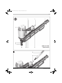
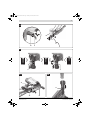
OBJ_BUCH-1037-001.book Page 1 Tuesday, December 8, 2009 1:15 PM Robert Bosch GmbH Power Tools Division 70745 Leinfelden-Echterdingen Germany www.bosch-pt.com 1 609 929 U15 (2009.12) PS / 352 UNI GSN Professional 90-21 RK | 90-34 DK de en fr es pt it nl da sv no fi Originalbetriebsanleitung Original instructions Notice originale Manual original Manual original Istruzioni originali Oorspronkelijke gebruiksaanwijzing Original brugsanvisning Bruksanvisning i original Original driftsinstruks Alkuperäiset ohjeet el tr pl cs sk hu ru Πρωτότυπο οδηγιών χρήσης Orijinal işletme talimat Instrukcja oryginalna Původní návod k používání Pôvodný návod na použitie Eredeti használati utasítás Оригинальное руководство по эксплуатации uk Оригінальна інструкція з експлуатації ro Instrucţiuni originale bg Оригинална инструкция sr sl hr et lv lt ar fa Originalno uputstvo za rad Izvirna navodila Originalne upute za rad Algupärane kasutusjuhend Instrukcijas oriģinālvalodā Originali instrukcija ΔϴϠλϷ ϞϴϐθΘϟ ΕΎϤϴϠόΗ ̶Ϡλ έΎ̯ ίήσ ̵ΎϤϨϫέ OBJ_BUCH-1037-001.book Page 3 Tuesday, December 8, 2009 1:03 PM |3 5 6 7 4 3 2 1 11 A 10 9 8 GSN 90-21 RK Professional 13 12 6 Bosch Power Tools 1 609 929 U15 | (8.12.09) OBJ_BUCH-1037-001.book Page 4 Tuesday, December 8, 2009 1:03 PM 4| B1 ≥5 7 14 B2 7 C 10 1 609 929 U15 | (8.12.09) 9 Bosch Power Tools OBJ_BUCH-1037-001.book Page 5 Tuesday, December 8, 2009 1:03 PM |5 D 10 9 E 3 3 F1 F2 16 17 15 Bosch Power Tools 8 1 609 929 U15 | (8.12.09) OBJ_BUCH-1037-001.book Page 6 Tuesday, December 8, 2009 1:03 PM 6| F3 G 19 16 21 20 22 15 H 18 I 24 23 J 6 1 609 929 U15 | (8.12.09) Bosch Power Tools OBJ_BUCH-1037-001.book Page 20 Tuesday, December 8, 2009 1:03 PM 20 | English Safety Notes en General Safety Rules for Pneumatic Tools WARNUNG Read and observe all safety warnings and instructions. Failure to follow the following safety warnings and instructions may result in electric shock, fire and/or serious injury. Save all warnings and instructions for future reference. 1) Work area safety a) Keep work area clean and well lit. Cluttered or dark areas invite accidents. b)Do not operate the pneumatic tool in explosive at- 3) Personal safety a) Stay alert, watch what you are doing, and use common sense when operating a pneumatic tool. Do not use a pneumatic tool while tired or under the influence of drugs, alcohol, or medication. A moment of inattention while operating a pneumatic tool may result in personal injury. b)Use personal protective equipment. Always wear eye protection. Protective equipment such as dust mask, non-skid safety shoes, hard hat, or hearing protection used for appropriate conditions will reduce personal injuries. c) Prevent unintentional starting. Make sure that the pneumatic tool is switched off before connecting mospheres, such as in the presence of flammable it to the air supply, picking it up or carrying it. liquids, gases or dusts. While working the work- When your finger is on the On/Off switch while car- piece, sparks can be created which may ignite the rying the pneumatic tool or when connecting the dust or fumes. pneumatic tool to the air supply while it is switched c) Keep children and bystanders away from your workplace while operating the pneumatic tool. Dis- on, accidents can occur. d)Remove any adjustment tools before switching on tractions from other persons can cause you to lose the pneumatic tool. A wrench or key left attached to control over the pneumatic tool. a rotating part of a pneumatic tool may result in personal injury. 2) Pneumatic tool safety a) Use compressed air of Quality Class 5 in accordance with DIN ISO 8573-1 and a separate maintenance unit close to the pneumatic tool. The compressed air supplied should be free of foreign material and moisture to protect the pneumatic tool from damage, contamination, and the formation of rust. b)Check the connections and the air supply lines. All maintenance units, couplers, and hoses should conform to the product specifications in terms of pressure and air volume. Too low pressure impairs the function of the pneumatic tool; too high pressure can result in material damage and personal injury. c) Protect the hoses from kinks, restrictions, solvents, and sharp edges. Keep the hoses away from heat, oil, and rotating parts. Immediately replace a damaged hose. A defective air supply line may result in a wild compressed-air hose and can cause personal injury. Raised dust or chips may cause serious eye injury. d)Make sure that hose clamps are always tightened firmly. Loose or damaged hose clamps may result in uncontrolled air escape. e)Do not overreach. Keep proper footing and balance at all times. This enables better control of the pneumatic tool in unexpected situations. f) Dress properly. Do not wear loose clothing or jewellery. Keep your hair, clothing and gloves away from moving parts. Loose clothes, jewellery or long hair can be caught in moving parts. g) If devices are provided for the connection of dust extraction and collection facilities, ensure these are connected and properly used. Use of dust collection can reduce dust-related hazards. h)Do not directly inhale the exhaust air. Avoid exposing the eyes to exhaust air. The pneumatic tool's exhaust air can contain water, oil, metal particles and debris from the compressor. This can cause damage to one's health. 4) Pneumatic tool use and care a) Use the clamping devices or a vice to secure and support the workpiece. Holding the workpiece by hand or against your body will not allow for safe operation of the pneumatic tool. b)Do not overload the pneumatic tool. Use the pneumatic tool intended for your work. The correct pneumatic tool will do the job better and safer at the rate for which it is designed. 1 609 929 U15 | (8.12.09) Bosch Power Tools OBJ_BUCH-1037-001.book Page 21 Tuesday, December 8, 2009 1:03 PM English | 21 c) Do not use a pneumatic tool that has a defective On/Off switch. A pneumatic tool that cannot be controlled with the switch is dangerous and must be repaired. Safety Warnings for Compressed-air Nailers/Staplers Wear safety goggles. d)Disconnect the air supply before making any adjustments, changing accessories, or placing the pneumatic tool aside. This safety measure prevents accidental starting of the pneumatic tool. e)Store idle pneumatic tools out of the reach of children. Do not allow persons unfamiliar with the pneumatic tool or these instructions to operate the device. Pneumatic tools are dangerous in the hands of untrained users. f) Maintain the pneumatic tool with care. Check for misalignment or binding of moving parts, breakage of parts and any other condition that may affect the pneumatic tool's operation. Have damaged parts repaired before using the pneumatic tool. Many accidents are caused by poorly maintained pneumatic tools. g) Use the pneumatic tool, accessories, application tools, etc. according to these instructions. Take into consideration the working conditions and the activities to be carried out. Use of the pneumatic tool for operations different from those intended could result in hazardous situations. 5) Service a) Have your pneumatic tool repaired only through a qualified repair person and only using original replacement parts. This will ensure that the safety of the pneumatic tool is maintained. f Always assume that the pneumatic tool is loaded with fasteners. Careless handling of the pneumatic tool can lead to unexpected shot actuation of fasteners and cause injury. f When working, hold the pneumatic tool in such a manner that your head and body cannot be injured in case of sudden kickback due to a malfunction of the energy supply or from hard objects/locations in the workpiece. f Never point the pneumatic tool at yourself or at persons close by. Unexpected actuation will expel a fastener, which can lead to injury. f Do not actuate the pneumatic tool until firmly placed against the workpiece. When the pneumatic tool is not in contact with the workpiece, the fastener can bounce away from the fastening point and overload the pneumatic tool. Do not work on ladders or scaffolds when the actuation system “Contact actuation” is set. In particular, do not move from one fastening location to another, close boxes or enclosures, or fasten transport-securing fixtures on e.g., vehicles and waggons, via scaffolds, stairs, ladders or ladder-like constructions, such as roof battens. With this actuation system, a fastener will be discharged each time when accidentally applying the pneumatic tool while the discharge lock-off is pressed in. This can lead to injury. f Observe the conditions of the job site. It is possible that fasteners can burst through thin workpieces or be deflected when working in corners or against edges, and harm persons. Disconnect the air supply, when the fastener is jammed in the pneumatic tool. When the pneumatic tool is still connected to the power supply, it can accidentally be actuated when removing a jammed fastener. f Use caution when removing a jammed or stuck fastener. The system can be under tension and cause the fastener to be shot or thrust out, while attempting to clear the jam. Bosch Power Tools 1 609 929 U15 | (8.12.09) OBJ_BUCH-1037-001.book Page 22 Tuesday, December 8, 2009 1:03 PM 22 | English f Do not use this to pneumatic tool to fasten electrical f The pneumatic tool may only be connected to lines, wiring. It is not suitable for fastening electrical wiring, for which the maximal permissible pressure of the can damage the insulation of electric cables and thus pneumatic tool cannot be exceeded by more than lead to electric shock and danger of fire. 10 %; for higher pressures, a pressure control valve f Never use oxygen or flammable gases as the energy source for the pneumatic tool. Flammable gases are dangerous and can cause the pneumatic tool to explode. f Use appropriate detectors to determine if utility lines (pressure reducer) with preceding pressure-limitation valve in the compressed-air line must be installed. Excessive pressure leads to abnormal operation or breakage of the pneumatic tool, which can lead to injury. are hidden in the work area or call the local utility company for assistance. Contact with electric lines can lead to fire and electric shock. Damaging a gas line can lead to explosion. Penetrating a water line causes property damage or may cause an electric shock. Functional Description Read all safety warnings and all instructions. 7 Magazine slider Failure to follow the warnings and instructions 8 Magazine may result in electric shock, fire and/or serious 9 Selector switch for actuation system injury. 10 Trigger 11 Outlet Intended Use 12 Air-connection coupling The pneumatic tool is intended for connecting work in 13 Supply-air hose roofing, encasing, battening, manufacturing wall and ceil- 14 Nail strip* ing elements, wood facades, pallets, wood fences, noisereduction walls and boxes. Only the fasteners (nails, staples, etc.) specified in table “Technical Data” may be used. Product Features The numbering of the product features refers to the illustration of the pneumatic tool on the graphics page. 15 Magazine lock 16 Lock pin 17 Driver blade 18 Magazine holder 19 Magazine retainer at shot duct 20 Magazine rail 21 Locking screw 22 Cover lid 1 Workpiece protector 23 Spring clip 2 Discharge lock-off 24 Screwable eyelet for pneumatic tool suspension 3 Depth stop 4 Air outlet 5 Handle *Accessories shown or described are not part of the standard delivery scope of the product. A complete overview of accessories can be found in our accessories program. 6 Air connector 1 609 929 U15 | (8.12.09) Bosch Power Tools OBJ_BUCH-1037-001.book Page 23 Tuesday, December 8, 2009 1:03 PM English | 23 Technical Data Compressed-air nailer GSN 90-21 RK GSN 90-34 DK Professional Professional 3 601 D91 0.. 3 601 D91 3.. 98 96 – Single actuation with safety run z z – Contact actuation z z Article number Driving force at 6.3 bar (91 psi) Nm Actuation systems Fastener – Type Nail strip Nail strip Plastic-bonded Paper-bonded Round head D-head – Length mm 50 – 90 50 – 90 – Diameter mm 2.8 – 3.8 2.8 – 3.8 ° 21 34 73 99 Magazine angle Magazine capacity, max. Engine oil SAE 10, SAE 20 ml 0.25 – 0.5 0.25 – 0.5 Internal volume ml 997 997 Rated pressure bar 4–8 4–8 " 3/8 3/8 bar 10 10 Connecting thread Supply-air hose – Max. operating pressure at 20 °C – Inner diameter of hose " 3/8 3/8 m 30 30 l 3.02 3.02 – Height mm 342 355 – Width mm 105 105 – Length mm 542 485 kg 3.89 3.8 – Max. hose length Air consumption per driving procedure at 6.8 bar (100 psi) Dimensions Weight according to EPTA-Procedure 01/2003 Noise/Vibration Information Measured noise values determined according to EN 12549. Typically the A-weighted noise levels of the pneumatic tool are: Sound pressure level 110 dB(A); sound power level 123 dB(A). Uncertainty K=2 dB. Wear hearing protection! Overall vibrational values (vector sum of three directions) determined according to EN 28662 and EN ISO 8662. Vibrational emission value ah <2.5 m/s2. Uncertainty K = 1.5 m/s2. Bosch Power Tools 1 609 929 U15 | (8.12.09) OBJ_BUCH-1037-001.book Page 24 Tuesday, December 8, 2009 1:03 PM 24 | English Declaration of Conformity We declare under our sole responsibility that the product described under “Technical data” is in conformity with the following standards or standardization documents: EN 792 according to the provisions of the directives 98/37/EC (until 28 Dec 2009), 2006/42/EC (from 29 Dec 2009). – Connect the air connector 6 with a supply-air hose 13 equipped with an air-connection coupling 12. – Check the proper function by placing the outlet 11 or the rubber workpiece protector 1 of the pneumatic tool onto a piece of scrap wood or wood material, and discharging once or twice. Loading the Magazine (see figures B1 – B2) Technical file at: Disconnect the air supply before making any Robert Bosch GmbH, PT/ESC, adjustments, changing accessories, or plac- D-70745 Leinfelden-Echterdingen Dr. Egbert Schneider Dr. Eckerhard Strötgen Senior Vice President Head of Product Engineering Certification ing the pneumatic tool aside. This safety measure prevents accidental starting of the pneumatic tool. f Use only original Bosch accessories (see “Technical Data”). The precision parts of the pneumatic tool such as the magazine, the outlet and the shot duct are Robert Bosch GmbH, Power Tools Division D-70745 Leinfelden-Echterdingen Leinfelden, 08.12.2009 matched to Bosch staples, nails and brads. Other manufacturers use other steel qualities and sizes. Using fasteners not permitted, can damage the pneumatic tool and cause injuries. Assembly While loading the magazine, hold the pneumatic tool in such a manner that the outlet 11 is not pointed at your own body or at other persons. Connecting the Air Supply (see figure A) Make sure that the pressure of the compressed-air sys- – Pull back the magazine slider 7 until it engages at the rear. tem is below the maximum permitted rated pressure of Note: The magazine slider must slide back with only low the pneumatic tool. Firstly, set the air pressure to the force (finger-pressure). A tight-running magazine slider lower value of the recommended rated pressure (see causes the nails to be driven in at an incorrect angle. “Technical Data”). – Clean and lubricate the magazine slider 7 as required When in doubt, check the pressure at the air inlet with a pressure gauge with the pneumatic tool switched on. and make sure that the magazine 8 is not dirty/soiled. – Insert a fitting nail strip 14. For maximum performance, the values for the supply-air Do not use nail strips with less than 5 nails. Do not in- hose 13 (connection thread, maximum operating pres- sert more than 2 nail strips. Make sure that the heads sure, inner hose diameter, maximum hose length; see of the nails do not overlap. “Technical Data”) must be observed. GSN 90-34 DK: With this pneumatic tool, a lock function The compressed air supplied should be free of foreign of the magazine slider prevents the last nails from being material and moisture to protect the tool from damage, discharged. Approx. 7 nails remain in the magazine. contamination, and the formation of rust. – Completely pull back the magazine slider 7 once more All fittings, connecting lines and hoses must be dimensioned for the pressure and the required air volume. to free the lock. – Carefully guide the magazine slider to the front until it Avoid restrictions in the air supply, e.g., from pinching, touches the nail strip. kinking, or stretching! Make sure that the magazine slider is slid beyond the head of the last nail. Connecting the Air Supply to the Pneumatic Tool – Empty the magazine 8. (See “Emptying the Magazine”, page 26) For the following worksteps, a fastener can be discharged when interior parts of the pneumatic tool are Note: Do not let the magazine slider snap back without guiding it. Otherwise, the magazine slider could become damaged, and there is danger of your fingers being caught or pinched. not in the starting position due to repairs, maintenance or transport. 1 609 929 U15 | (8.12.09) Bosch Power Tools OBJ_BUCH-1037-001.book Page 25 Tuesday, December 8, 2009 1:03 PM English | 25 Operation Working with Contact Actuation (see figure D) – Press selector switch 9 inward and at the same time Actuation systems pivot it to the upper position until it engages. The actuation system “contact ac- The pneumatic tool can be operated with two different tuation” is set. actuations systems: – Single actuation with safety run – Release the selector switch 9 again. With this actuation system, the discharge lock-off 2 – Press and hold the trigger 10. must first be firmly pressed against the workpiece. A – Firmly position the outlet 11 or the rubber workpiece fastener is not discharged until the trigger 10 is pulled. protector 1 on the workpiece until discharge lock-off 2 Afterwards, further discharging procedures can only is pressed in completely. be actuated, when the trigger and the discharge lock- A nail is discharged. off have first been set back to the starting position. – Contact actuation With this actuation system, the trigger 10 must be pulled first. A fastener is always discharged when the discharge lock-off 2 is firmly pressed against the workpiece while the trigger is pressed. This enables a higher working speed to be achieved. The actuation system is set via the selector switch 9. – Allow the pneumatic tool to bounce back from the workpiece. – For another driving procedure, completely lift the pneumatic tool from the workpiece and position it firmly at the next desired location. – Move the pneumatic tool uniformly over the workpiece by lifting it off and applying it again. Each time when applying the pneumatic tool while the discharge lock-off is pressed in, a nail will be dis- Starting Operation Disconnect the air supply before making any adjustments, changing accessories, or plac- charged. – As soon as the desired amount of nails have been driven in, release trigger 10 again. ing the pneumatic tool aside. This safety measure prevents accidental starting of the pneumatic tool. Working Advice Disconnect the air supply before making any adjustments, changing accessories, or plac- Working with Single Actuation (see figure C) ing the pneumatic tool aside. This safety – Press selector switch 9 inward and at the same time measure prevents accidental starting of the pivot it to the bottom position until it engages. pneumatic tool. The actuation system “single actua- Check the proper function of the safety and actuation de- tion” is set. vices, and the tight seating of all screws and nuts each time before using. – Release the selector switch 9 again. Disconnect a defective or not properly operating pneu- – Firmly position the outlet 11 or the rubber workpiece matic tool immediately from of the air supply and contact protector 1 on the workpiece until discharge lock-off 2 an authorised service agent for Bosch power tools. is pressed in completely. Do not perform any incorrect manipulations on the pneu- – Afterwards, briefly press trigger 10 and release again. A nail is discharged. – Allow the pneumatic tool to bounce back from the workpiece. – For another driving procedure, completely lift the matic tool. Do not disassemble or block any components of the pneumatic tool, such as the discharge lock-off. Do not carry out “emergency repairs” with unsuitable means. The pneumatic tool is to be maintained regularly and properly (see “Maintenance and Cleaning”, page 27). pneumatic tool from the workpiece and position it firmly at the next desired location. Bosch Power Tools 1 609 929 U15 | (8.12.09) OBJ_BUCH-1037-001.book Page 26 Tuesday, December 8, 2009 1:03 PM 26 | English Avoid any weakening and damage whatsoever of the To increase the driving depth, turn the depth stop an- pneumatic tool, e.g., through: ticlockwise. – Imprinting or engraving, – Retrofitting measures not approved by the manufacturer, – Guiding along templates manufactured of hard materi- – Refill the magazine. (See “Loading the Magazine”, page 24) – Test the new driving depth on a test workpiece. Repeat the worksteps as required. al, e.g. steel, – Dropping on or sliding over the floor, Clearing Jams (see figures F1 – F3) – Using as a hammer, Single nails can become jammed in the shot duct. If this – Applying any kind of force. should occur frequently, please contact an authorised Make sure to check whatever is below or behind your workpiece. Do not shoot nails into walls, ceilings or floors, when persons are behind them. The nails can burst through the workpiece and injure someone. Do not shoot a nail onto an already driven-in one. This could cause the nail to deform, the nails could become jammed or the pneumatic tool could move uncontrolled. When the pneumatic tool is used under cold ambient conditions, the first nails will be driven in slower than usual. Once the pneumatic tool has warmed up during working, normal operating speed will be regained. Avoid blank shots in order to reduce the wear of the impact striker. For longer work breaks or after finishing work, disconnect the pneumatic tool from the air supply and empty the magazine. Emptying the Magazine – Pull back the magazine slider 7 until it engages at the rear. – Remove the nail strips 14. Discard nail strips with less than 5 nails. – Completely pull back the magazine slider 7 once more to free the lock. – Carefully guide the magazine slider to the front until it touches the beginning of the magazine. Note: Do not let the magazine slider snap back without guiding it. Otherwise, the magazine slider could become damaged, and there is danger of your fingers being caught or pinched. Adjusting the Depth Stop (see figure E) The driving depth of the nails can be set with depth stop 3. – Empty the magazine 8. (See “Emptying the Magazine”, page 26) – To reduce the driving depth, turn the depth stop clockwise. service agent for Bosch power tools. – Empty the magazine 8. (See “Emptying the Magazine”, page 26) – Open the magazine lock 15. – Pull the magazine 8 away from the housing until it slips off of lock pin 16. This makes the jammed nail in the shot duct accessible. – Remove the jammed nail. For this, us a pair of pliers, if required. – When driver blade 17 is extended, push it back into the piston using a lubricated screwdriver or other suitable lubricated object. – Lubricate the shot duct with 2 – 3 drops of engine oil (SAE 10 or SAE 20). – Reinsert the magazine 8 again: Open the magazine lock 15, if required. Guide lock pin 16 into the opening of magazine holder 18. Align the magazine to magazine retainers 19 and push the magazine completely to the front. Lock the magazine by completely folding magazine lock 15 up. – Refill the magazine. (See “Loading the Magazine”, page 24) Changing a Magazine Rail (see figure G) The magazine rails 20 can wear after prolonged use of the pneumatic tool. Replace defective magazine rails. – Empty the magazine 8. (See “Emptying the Magazine”, page 26) – Loosen locking screw 21 (3 mm) with the supplied Allen key. – Pull cover lid 22 out of the magazine 8. – Allow the defective magazine rails 20 to slide out of the magazine. – Insert new magazine rails into the magazine. – Insert cover lid 22 back into the magazine and tighten locking screw 21. or 1 609 929 U15 | (8.12.09) Bosch Power Tools OBJ_BUCH-1037-001.book Page 27 Tuesday, December 8, 2009 1:03 PM English | 27 Changing the Workpiece Protector (see figure H) The workpiece protector 1 at the end of the discharge – Remove the rear screw of the exhaust cap with the supplied Allen key. lock-off 2 protects the workpiece until the pneumatic tool – Screw the eyelet 24 firmly into the exhaust cap. is correctly placed for the driving procedure. – Hook the eyelet to the balancer hook. The workpiece protector can be removed and replaced. – Remove spring clip 23 and pull the workpiece protector from the discharge lock-off 2. – Push the new workpiece protector over the discharge lock-off and mount the spring clip again. Transport and Storage For transport, disconnect the pneumatic tool from the air supply; especially when using ladders or moving in an unusual stance or posture. At the workplace, carry the pneumatic tool only by the Stationary Use of the Pneumatic Tool (see figure I) handle 5 and with the trigger 10 released. For stationary use, the pneumatic tool can be fastened to Always store the pneumatic tool disconnected from the a balancer. air supply and at a clean and dry location. The screwable eyelet 24 is required for this. When not using the pneumatic tool for a longer period of time, cover steel parts with a fine oil coating. This prevents the formation of rust. Maintenance and Service Maintenance and Cleaning Disconnect the air supply before making any Lubricating the Pneumatic Tool (see figure J) adjustments, changing accessories, or plac- When the pneumatic tool is not connected to a mainte- ing the pneumatic tool aside. This safety measure prevents accidental starting of the pneumatic tool. If the pneumatic tool should fail despite the care taken in manufacture and testing, repair should be carried out by an authorised customer services agent for Bosch power tools. nance unit, it must be lubricated at regular intervals: – For light-duty use 1x per day. – For heavy-duty use 2x per day. Apply 2 – 3 drops of lubricant into air connector 6. Do not apply too much lubricant, which could then accumulate in the pneumatic tool and be emitted via air outlet 4. In all correspondence and spare parts orders, please al- Use only the lubricants recommended by Bosch. ways include the 10-digit article number given on the type – SAE 10 mineral engine oil (for use at very cold ambient plate of the pneumatic tool. f Have maintenance and repair work carried out only conditions) – SAE 20 mineral engine oil through qualified persons. This will ensure that the Observe all applicable environmental regulations when safety of the pneumatic tool is maintained. disposing of old grease and solvents. An authorized Bosch after-sales service agent will carry out this work quickly and reliably. Bosch Power Tools 1 609 929 U15 | (8.12.09) OBJ_BUCH-1037-001.book Page 28 Tuesday, December 8, 2009 1:03 PM 28 | English Maintenance Schedule Always keep air outlet 4, discharge lock-off 2 and trigger Clean the magazine 8. Remove any plastic or wood chips 10 clean and free of foreign material (dust, chips, sand, that may accumulate in the magazine during operation. etc). Clean the pneumatic tool in regular intervals using compressed air. Measure Explanation Action Draining the exhaust filter daily. Prevents the accumulation of dirt/ – Open the drain valve. debris and moisture in the pneumatic tool. Keeping the lubricator filled at all Ensures the lubrication of the pneu- times. matic tool. – Fill lubricator with the recommended lubricants. (See “Lubricating the Pneumatic Tool”, page 27) Cleaning the magazine 8 and maga- Prevents the jamming of nails. zine slider 7. – Blow out the mechanism of the magazine/magazine slider daily with compressed air. Ensuring that the discharge lock-off 2 Promotes your work safety and effifunctions properly. cient usage of the pneumatic tool. – Blow out the mechanism of the discharge lock-off daily with compressed air. Lubricating the pneumatic tool. Reduces the wear of the pneumatic tool. – Apply 2 – 3 drops of lubricant into air connector 6. (See “Lubricating the Pneumatic Tool”, page 27) Draining the compressor. Prevents the accumulation of dirt/ debris and moisture in the pneumatic – Open the drain valve of the compressor tank. tool. 1 609 929 U15 | (8.12.09) Bosch Power Tools OBJ_BUCH-1037-001.book Page 29 Tuesday, December 8, 2009 1:03 PM English | 29 Correction of Malfunctions Problem Cause The pneumatic tool is ready for A nail is jammed in the shot duct. – Clear the jam. (See “Clearing Jams”, page 26) operation but no nails are discharged. Corrective Measure The magazine slider is 7 defective. – Clean and lubricate the magazine slider 7 as required and make sure that the magazine 8 is not dirty/soiled. The spring of the magazine slider is too week or defective. – Contact an authorised service agent for Bosch power tools. Have the component replaced there. The fasteners being used are not permitted. – Use only original accessories. Only the fasteners (nails, staples, etc.) specified in table “Technical Data” may be used. The magazine 8 is empty. – Refill the magazine. (See “Loading the Magazine”, page 24) The nails are discharged very The rated pressure of the compressed- slowly and with too little pres- air supply is too low. sure. The driver blade is damaged. – Increase the compressed-air supply. 8 bar may not be exceeded. – Use only the lubricants recommended by Bosch. (See “Lubricating the Pneumatic Tool”, page 27) The sealing ring of the piston is worn or – Contact an authorised service agent for damaged. Bosch power tools. Have the component replaced there. The buffer is worn. – Contact an authorised service agent for Bosch power tools. Have the component replaced there. The length and diameter of supply-air – Use a supply-air hose with the correct hose 13 do not correspond with the data dimensions. of this pneumatic tool. (See “Technical Data”, page 23) The supply-air hose 13 is bent/creased. – Correct the bend/crease in the supplyair hose. The nails are driven in too deep. The rated pressure of the compressedair supply is too high. The depth stop is set too deep. – Reduce the compressed-air supply. 4 bar may not be fallen below. – Adjust the depth stop to the desired depth. (See “Adjusting the Depth Stop”, page 26) The buffer is worn. – Contact an authorised service agent for Bosch power tools. Have the component replaced there. Bosch Power Tools 1 609 929 U15 | (8.12.09) OBJ_BUCH-1037-001.book Page 30 Tuesday, December 8, 2009 1:03 PM 30 | English Problem Cause The nails are not driven in deep The rated pressure of the compressedenough. air supply is too low. The depth stop is set too high. Corrective Measure – Increase the compressed-air supply. 8 bar may not be exceeded. – Adjust the depth stop to the desired depth. (See “Adjusting the Depth Stop”, page 26) The length and diameter of supply-air – Use a supply-air hose with the correct hose 13 do not correspond with the data dimensions. of this pneumatic tool. (See “Technical Data”, page 23) The supply-air hose 13 is bent/creased. – Correct the bend/crease in the supplyair hose. The pneumatic tool skips nails The fasteners being used are not or has a too large cycle feed. permitted. – Use only original accessories. Only the fasteners (nails, staples, etc.) specified in table “Technical Data” may be used. The magazine 8 is not operating correctly. – Clean and lubricate the magazine slider 7 as required and make sure that the magazine 8 is not dirty/soiled. The spring of the magazine slider is too week or defective. – Contact an authorised service agent for Bosch power tools. Have the component replaced there. The sealing ring of the piston is worn or damaged. – Contact an authorised service agent for Bosch power tools. Have the component replaced there. Frequent jamming of nails in the The fasteners being used are not shot duct. permitted. – Use only original accessories. Only the fasteners (nails, staples, etc.) specified in table “Technical Data” may be used. – Contact an authorised service agent for Bosch power tools. The driven nails are bent. The driver blade is damaged. – Contact an authorised service agent for Bosch power tools. Have the component replaced there. Contrary to working with nor- The interior diameter of the supply-air mal operating speed, the nails hose is too low. are not driven in deep enough at higher operating speed. – Use a supply-air hose with the correct dimensions. (See “Technical Data”, page 23) The compressor is not suitable for fast operating speeds. – Use a compressor that is sufficiently dimensioned for the number of connected pneumatic tools and the operating speed. 1 609 929 U15 | (8.12.09) Bosch Power Tools OBJ_BUCH-1037-001.book Page 31 Tuesday, December 8, 2009 1:03 PM English | 31 Accessories For more information on the complete quality accessories program, please refer to the Internet under www.bosch-pt.com or contact your specialist shop. Republic of South Africa Customer service Hotline: +27 (011) 6 51 96 00 Gauteng – BSC Service Centre 35 Roper Street, New Centre Johannesburg After-sales Service and Customer Assistance Tel.: +27 (011) 4 93 93 75 Our after-sales service responds to your questions con- Fax: +27 (011) 4 93 01 26 cerning maintenance and repair of your product as well E-Mail: [email protected] as spare parts. Exploded views and information on spare KZN – BSC Service Centre parts can also be found under: Unit E, Almar Centre www.bosch-pt.com 143 Crompton Street Our customer service representatives can answer your Pinetown questions concerning possible applications and adjust- Tel.: +27 (031) 7 01 21 20 ment of products and accessories. Fax: +27 (031) 7 01 24 46 E-Mail: [email protected] Great Britain Western Cape – BSC Service Centre Robert Bosch Ltd. (B.S.C.) Democracy Way, Prosperity Park P.O. Box 98 Milnerton Broadwater Park Tel.: +27 (021) 5 51 25 77 North Orbital Road Fax: +27 (021) 5 51 32 23 Denham E-Mail: [email protected] Uxbridge Bosch Headquarters UB 9 5HJ Tel. Service: +44 (0844) 736 0109 Fax: +44 (0844) 736 0146 E-Mail: [email protected] Midrand, Gauteng Tel.: +27 (011) 6 51 96 00 Fax: +27 (011) 6 51 98 80 E-Mail: [email protected] Ireland Origo Ltd. Disposal Unit 23 Magna Drive The pneumatic tool, accessories and packaging should be Magna Business Park sorted for environmental-friendly recycling. City West When your unit is no longer suitable for use, please return Dublin 24 it to a specialist store or send it directly (sufficiently post- Tel. Service: +353 (01) 4 66 67 00 paid please) to: Fax: +353 (01) 4 66 68 88 Recyclingzentrum Elektrowerkzeuge Osteroder Landstr. 3 Australia, New Zealand and Pacific Islands 37589 Kalefeld Robert Bosch Australia Pty. Ltd. The units will be disassembled. Plastics, e.g., the housing Power Tools which are primarily made of polyamide, are identified Locked Bag 66 (Bosch detection code for plastics since 1992) and recy- Clayton South VIC 3169 cled. Iron, steel, aluminium and cast parts are melted in a Customer Contact Center high-temperature furnace and recycled. Copper scrap is Inside Australia: shredded (without heat) and returned to the copper in- Phone: +61 (01300) 307 044 dustry as copper granulate. Fax: +61 (01300) 307 045 Subject to change without notice. Inside New Zealand: Phone: +64 (0800) 543 353 Fax: +64 (0800) 428 570 Outside AU and NZ: Phone: +61 (03) 9541 5555 www.bosch.com.au Bosch Power Tools 1 609 929 U15 | (8.12.09)