1
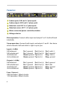
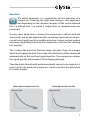
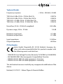
xpressor
Precautions
WARNING: High Voltage
• Risk of electric shock.
• Do not open chassis.
• Refer service to qualified service staff only.
• Before connecting the device to the main power supply, check if the
right voltage is selected.
• Replace fuse with the same type and value only.
• This device must be connected to ground.
• Do not use a damaged power cord.
• Never place containers with liquid, e.g. beverages or a vase, on the unit.
• Do not expose this device to rain or moisture.
• Do not use this device near water, e.g. swimming pool, bathtub or wet
basement.
CAUTION: Temperature
• Surfaces of the device may become hot during operation.
• Do not install this device near any heat source such as radiators, stoves
or other heat sources.
• Always allow enough ventilation space around the unit for air circulation.
• Do not cover circulation vents.
CAUTION: Connecting & Mounting
• Never connect the output of a power amplifier to this device.
• Place the unit on a rigid board or place it in an appropriate rack.
• Use the device according to this manual only.
CAUTION: Humidity
• If this device is moved from a cold place to a warm room, condensation
can occur inside the device. To avoid damaging the unit, please allow it
to reach room temperature before switching it on.
2
Welcome to Compressor Wonderland!
First of all, we would like to thank you for picking the xpressor as your
new dynamics tool – a very good choice indeed.
This extremely versatile stereo compressor will make your day in terms of
dynamics time and again. With its many unique features taken from our
flagship products, you not only get great compression, but an amount of
control on processing which has yet to be experienced elsewhere.
No matter if you want to set and forget or plunge deep into the secrets
of compression, the xpressor is for you. Its discrete audio path running
in constant class-A mode provides a superior audio quality which combines a clear and open sound with a good lot of punch.
Stereo buss compression, processing single signals, approaching dynamics in creative ways – the xpressor shines in many different applications.
Best of elysia? You got it!
Index
Controls. . . . . . . . . . . . . . . . . . . . . . . . . . . . . . . . . . . . . . . . . . . . . . . . . . . . . . . . . . . . . . 4
Connectors. . . . . . . . . . . . . . . . . . . . . . . . . . . . . . . . . . . . . . . . . . . . . . . . . . . . . . . . . . . 6
Auto Fast. . . . . . . . . . . . . . . . . . . . . . . . . . . . . . . . . . . . . . . . . . . . . . . . . . . . . . . . . . . . . 7
Log Release. . . . . . . . . . . . . . . . . . . . . . . . . . . . . . . . . . . . . . . . . . . . . . . . . . . . . . . . . . . 8
Warm Mode . . . . . . . . . . . . . . . . . . . . . . . . . . . . . . . . . . . . . . . . . . . . . . . . . . . . . . . . . . 9
Negative Ratios. . . . . . . . . . . . . . . . . . . . . . . . . . . . . . . . . . . . . . . . . . . . . . . . . . . . . 10
Gain Reduction Limiter. . . . . . . . . . . . . . . . . . . . . . . . . . . . . . . . . . . . . . . . . . . . . . 11
External Sidechain. . . . . . . . . . . . . . . . . . . . . . . . . . . . . . . . . . . . . . . . . . . . . . . . . . 12
Technical Details. . . . . . . . . . . . . . . . . . . . . . . . . . . . . . . . . . . . . . . . . . . . . . . . . . . . 13
CE Conformity. . . . . . . . . . . . . . . . . . . . . . . . . . . . . . . . . . . . . . . . . . . . . . . . . . . . . . 13
Warranty Info. . . . . . . . . . . . . . . . . . . . . . . . . . . . . . . . . . . . . . . . . . . . . . . . . . . . . . . 14
Legal Info. . . . . . . . . . . . . . . . . . . . . . . . . . . . . . . . . . . . . . . . . . . . . . . . . . . . . . . . . . . 15
3
Controls
Thresh
XPRESSOR
DISCRETE CLASS-A
STEREO COMPRESSOR
Attack
-22
-27
7
12
-32
17
-37
22
dB
-42
Release
40
60
7.0
3.5
80
0.5
100
0.01
ms
120
Ratio
250
400
25
12
700
7
1k0
5
ms
1k3
∞
-0.4
2.0
Hit
Warm
Log
Auto
It!
Mode
Rel
Fast
-0.8
1.6
1.3
-1.2
1.2
1:X
-1.6
Threshold (Thresh): The operating point of the compressor. If the
input level exceeds the value set with this controller, the compression
process will start.
Attack: The transient response of the compressor. It determines the
time the xpressor needs to reach 10 dB of gain reduction.
Release: The return phase of the compressor. It controls the period of
time between the input signal falling below the threshold and the xpressor’s return to unity gain.
Ratio: The relation between the input level and the output level. As
a specialty of the xpressor, even negative ratios can be set here. (p. 10)
Hit It! Activates the xpressor (LED on) or deactivates it with a hardwire
bypass (GR meter remains active).
Warm Mode: The xpressor offers a second switchable sound flavor by
altering its frequency spectrum, harmonics and transient response. (p. 9)
Log Release (Log Rel): This alternative release curve follows a logarithmic course instead of the standard linear progress and results in a
very gentle kind of compression. (p. 8)
Auto Fast: A semi-automation. This function shortens the attack time
automatically on fast and loud signal impulses and then returns to the
value set with the controller. (p. 7)
4
120
GRL
13
14
11
12
9.0
10
7.0
8.0
5.0
6.0
3.0
4.0
1.0
2.0
160 200
SCF
400
80
40
600
35
800
31
Hz
1k0
14
11
9.0
GRL
6.0
18
22
3.5
26
2.0
30
dB
1.5
4.0
5.5
7.0
Gain
11
3.0
1.5
15
0.2
19
0
dB
21
40
50
60
Mix
80
30
20
90
10
100
Dry
%
Wet
GRL LED: Indicates Gain Reduction Limiter activity. If this LED is on,
incoming signals will be held at the GR limit instead of being compressed
any further. (p. 11)
Gain Reduction Meter: The display for the gain reduction process.
Shows the amount of compression measured in dB as an visual support
for the acoustic events.
Sidechain Filter (SCF): A tunable low cut filter in the sidechain of the
xpressor avoids overcompression and pumping when there is a lot of low
end energy in the mix.
Gain Reduction Limiter (GRL): Restricts the control voltage. This innovative limiter is not placed in the audio path as usual, but in the control circuit of the compressor. (p. 11)
Gain: The make-up gain of the xpressor. This controller compensates
for the loss in gain caused by the compression process.
Mix: The direct and the compressed signal can be blended in any
desired relation by simply turning the mix controller. Onboard parallel
compression!
Please note that in stereo operation both channels are always processed by one single
control voltage generated from a mix of both signals. This means you should only
compress adequate stereo material like sum signals in this mode - dissimilar signals
like a bass drum in one channel and a synth pad in the other will not give you the
intended ‘dual mono’ results.
5
Connectors
OUT R
IN R
EXT 2
OUT R
AVIS: RISQUE DE CHOC ÉLECTRIQUE - NE PAS OUVRIR
IN R
MADE IN GERMANY
OUT R
IN R
IN R
EXT 1
OUT L
EXT 1
OUT L
IN L
IN L
230V
OUT R
OUT L
xpressor
serial number
RISK OF ELECTRIC SHOCK
DO NOT OPEN
EXT 2
VOLTAGE
230V 100mA | 115V 200mA | slo-blo
OUT L
IN L
IN L
Audio inputs (XLR and ¼” phone jack)
Audio outputs (XLR and ¼” phone jack)
Sidechain send: EXT 2 (¼” phone jack)
Sidechain return: EXT 1 (¼” phone jack)
Mains connector/power switch/fuse holder
Voltage selector
Mono operation: Connect either input and output 1 or 2 - both will work
identically.
Stereo operation: Connect both inputs and outputs 1 and 2 - the choice
which channel is left and which is right is up to you.
Inputs (+4 dBu)
XLR balanced:
XLR unbalanced:
Jack balanced:
Jack unbalanced:
Pin 1: ground
Pin 1: ground
Sleeve: ground
Sleeve: ground
Pin 2: hot (+)
Pin 2: hot (+)
Tip: hot (+)
Tip: hot (+)
Pin 3: cold (-)
Pin 3: ground
Ring: cold (-)
Ring: ground
Outputs (+4 dBu)
XLR balanced:
XLR unbalanced:
Jack balanced:
Jack unbalanced:
Pin 1: ground
Pin 1: ground
Sleeve: ground
Sleeve: ground
Pin 2: hot (+)
Pin 2: hot (+)
Tip: hot (+)
Tip: hot (+)
Pin 3: ground
Pin 3: idle
Ring: ground
Ring: idle
Fuses (2 pieces)
230V operation: 100mA slo-blo
115V operation: 200mA slo-blo
6
Auto Fast
The attack parameter is a crucial factor for the operation of a
compressor. Choosing the right time setting is very important,
but depending on the dynamic progress of the source material
this is a difficult task – no matter if single tracks or complete mixes are
processed.
If a very short attack time is chosen, the compressor is able to catch the
short peaks, but on the other hand the sustaining signal will also be processed, which might result in audible distortion. Longer settings reduce
distortion significantly, but then the compressor is too slow for catching
fast impulses.
This is where the Auto Fast function comes into play. If you set a longer
attack and engage the Auto Fast mode, the attack time will be shortened
automatically on fast and loud signal impulses. The compressor reduces
the signal quickly and prevents it from slipping through.
Then the attack time directly and automatically returns to its original setting. In Auto Fast mode the compressor can be very fast, but only when
it is really needed.
Attack phase without Auto Fast
Output Level (dB)
Attack phase with Auto Fast
Output Level (dB)
Time (s)
Time (s)
7
Log Release
It is the time constants and especially the release parameter that
decide if the processing of a compressor is obvious or unobtrusive to the ear. As it is difficult to achieve perfect results for all
kinds of different material with only one type of release curve, the xpressor offers two different options to choose from: logarithmic and linear.
It is characteristic of a logarithmic release that the time constant shortens when the amount of gain reduction increases. The advantage of this
behavior is that short and loud peaks (e.g. drums) have a fast release
time, while the remaining material is processed with a slower release. Its
smooth performance makes the Log Release especially useful for mastering and stereo buss compression.
The linear mode, however, has a straight release profile, without the
slower tapering release characteristic of the Log mode. The linear mode
is a good choice for more aggressive dynamics control of dry signals,
and it is especially useful when you want to process signals which do not
have a long decay period.
Logarithmic release progress
Output Level (dB)
Output Level (dB)
Time (s)
8
Linear release progress
Time (s)
Warm Mode
This function is basically a slew rate limiter that reduces the
speed of the output amplifier stages. This affects the frequency
spectrum, the harmonics and the transient response at the same
time.
Fast transients are slowed down a bit and the overall sound appears
more round and merged. As this function influences the behavior of the
output stages, the effect it creates has an impact on the complete processing results of the compressor.
This way the xpressor offers two different sound characters at the push of
a button: the powerful transparency of the discrete class-A circuitry and
the saturated richness of the Warm Mode.
Now the choice is really up to you: For transparent compression and an
even frequency response, just use the xpressor in standard mode. For a
little bit more fat and juicy sound, hit the Warm Mode button and you
are there!
Added total harmonic distortion
THD+N (%)
Modified frequency response
Output Level (dB)
Frequency (Hz)
Frequency (Hz)
9
Negative Ratios
Negative ratios – what exactly does this mean? To get a better
understanding of this function, it makes sense to realize what
the ratio control of a ‘normal’ compressor does:
• 1:1 The signal remains linear, there is no compression process going
on.
• 1:2 After crossing the threshold, an increase of 2 dB at the input will be
compressed to an increase of 1 dB at the output.
• 1:∞ After crossing the threshold, the output signal is constantly held
at the threshold level without reacting to further increases at the
input (limiter).
At a negative ratio, the characteristic curve bends and returns back down
after crossing the threshold. The louder the input signal, the lower the
output signal – perfect for groovy compression effects.
To get a grip on the extreme ‘destruction’ this can cause, engaging the
Gain Reduction Limiter is just the right idea.
Standard compression ratio
Input Level (dB)
Input Level (dB)
Output Level (dB)
10
Negative compression ratio
Output Level (dB)
Gain Reduction Limiter
A specialty of the xpressor is the Gain Reduction Limiter for the
control voltage. This limiter is not placed in the audio path where
you would usually find it, but in the control path of the compressor instead.
When activated, it limits the control voltage according to the setting of
the GR Limit controller. This means: No matter how high the input level
might become – the amount of gain reduction will never exceed the value you have set.
Just think about the GRL as a second threshold controller: While the ‘regular’ threshold controller tells the compressor when to start working, the
GRL controller tells it when to compress no further.
Loud parts in an arrangement can keep their dynamics, as they will not
be compressed beyond the limit of the Gain Reduction Limiter.
Note: This function of the xpressor is always active and does not need a
switch of its own.
GRL compression progress
Output Level (dB)
GRL input to output ratio
Input Level (dB)
Attack phase
Release phase
GRL phase
GRL phase
Time (s)
Output Level (dB)
11
External Sidechain
The external sidechain enables the compressor to control its
processing totally independent from the audio material running
through it. If an additional audio source is connected to the external sidechain input of the xpressor, compression will not be triggered
by the signals from the regular audio inputs anymore, but by a different
signal which is fed into the sidechain input.
If, for example, a duplicate of the input signal is processed with an equalizer and then fed into the sidechain input, the result will be frequencydependent compression. Another example is to send the bass drum of a
drum machine into the sidechain input in order to achieve nice groovy
compression that is pumping in sync with the music.
The creative options are almost infinite. Compression can be exactly on
time or totally against it, which can of course be varied on the fly. Single
instruments can be given more space in a mix according to its rhythm.
All of a sudden, static sounds become vivid and sound really interesting!
In addition to the external sidechain input the xpressor features a send
output, which can be used to feed a summed copy of the input signals
e.g. to an EQ and then into the sidechain input - additional sends from
the DAW or the console are no longer needed.
Note: The sidechain send output (EXT 2) carries a buffered mono signal
which is generated from summing the left and right input signals.
Note: The external sidechain feature is activated by inserting a ¼“ phone
jack into the sidechain return input (EXT 1). To deactivate it, just remove
the jack from the EXT 1 connector.
12
Technical Details
Frequency response: <10 Hz - 400 kHz (-3.0 dB)
THD+N @ 0 dBu, 20 Hz - 22 kHz, Mix 0 %: THD+N @ 0 dBu, 20 Hz - 22 kHz, Mix 100 %: THD+N @ +10 dBu, 20 Hz - 22 kHz, Mix 0 %: THD+N @ +10 dBu, 20 Hz - 22 kHz, Mix 100 %: Noise floor, 20 Hz - 20 kHz (A-weighted): Dynamic range, 20 Hz - 22 kHz: 0.002 %
0.006 %
0.003 %
0.056 %
-94.0 dBu
115 dB
Maximum input level: Maximum output level: +21 dBu
+21 dBu
Input impedance: Output impedance: 10 kOhm
68 Ohm
CE Conformity
elysia GmbH, Ringstraße 82, 41334 Nettetal, Germany, declares with sole responsibility that this product complies with
the following norms and directives:
• 2006/95/EG Low Voltage Directive (formerly 73/23/EWG or 93/68/EWG)
• 89/336/EWG EMC (Electromagnetic Compatibility) Directive
• DIN EN 55103-1 EMC of audio equipment - Emission
• DIN EN 55103-2 EMC of audio equipment - Immunity
This declaration becomes invalid by any unapproved modification of the
device.
Nettetal, 01.07.2011 - Ruben Tilgner & Dominik Klaßen
13
Warranty Info
The xpressor is covered by a limited warranty for a period of 2 years
against defects in parts and labor from the date of purchase. Natural
wear is not covered by this warranty. Repairs or replacements will not
extend the warranty period.
The warranty is given to the original purchaser only and is not transferable. elysia will only give warranty on products purchased through authorized elysia dealers. The warranty will only be valid in the country of
the original purchase unless otherwise pre-authorized by elysia.
All warranties become void when the product has been damaged by
misuse, accident, neglect, modification, tampering or unauthorized alteration by anyone other than elysia authorized service personnel.
The warrantor assumes no liability for property damage or any other incidental or consequential damage whatsoever which may result from failure of this product. Any and all warrantees of merchantability and fitness
implied by law are limited to the duration of the expressed warranty.
elysia will not pay for express or overnight freight service or pay for shipments to locations outside Germany. All damages caused by transport
are not covered by this warranty.
This warranty gives you specific legal rights and you may also have other
rights which vary from state to state. Some of the above limitations may
not apply to you.
14
Legal Info
The information in this document is subject to change without further
notice and shall not be deemed as an obligation or warranty of any kind
by the manufacturer. No warranties, express or implied, are made with
regard to the quality, suitability or accuracy of this document.
The manufacturer reserves the right to change the contents of this document and/or the associated products at any time without the provision
of prior notice. The manufacturer shall not be held liable for damages of
any kind arising from the use, or the inability to use this product or its
documentation.
The information in this document is subject to copyright. All rights, technical changes and errata are reserved. No part of this manual may be
reproduced or transmitted in any form or for any purpose without the
explicitly written permission of the copyright holders.
elysia and xpressor are registered trademarks of elysia GmbH. Other
product and brand names contained in this document are used for identification purposes only. All registered trademarks, product designations
or brand names used in this document are the property of their respective owners.
This product is manufactured according to the 2002/95/
EC directive. The purpose of this directive of the European Union is the Restriction of Hazardous Substances
(RoHS) in electronic equipment in order to protect health and nature.
Dispose separately!
Version 1.0 © 2011 elysia GmbH
15
elysia GmbH
Ringstraße 82
41334 Nettetal
Germany
+49 2157 126040
[email protected]