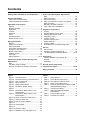
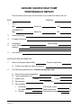
1
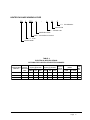
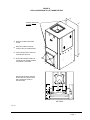
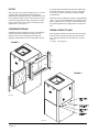
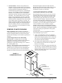
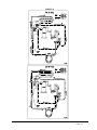
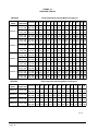
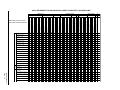
INSTALLATION INSTRUCTIONS WATER SOURCE HEAT PUMPS MODELS: GSVS241-A, GSVS301A GSVS361-A, GSVS421-A Earth Loop Fluid Temperatures 25° - 110° Ground Water Temperatures 45° - 75° BARD MANUFACTURING COMPANY Bryan, Ohio 43506 Since 1914...Moving ahead, just as planned. Manual: Supersedes: File: Date: 2100-317B 2100-317A Volume I, Tab 8 02-10-2000 Contents Getting Other Informations and Publications .... 1 Open Loop (Well System Applications) Note .............................................................. 20 Water Connection ................................................. 20 General Information Well Pump Sizing ................................................. 20 Water Source Nomenclature .................................. 2 Start Up Prodecure for Open Loop System ......... 22 Heater Package Nomenclature .............................. 5 Water Corrosion .................................................... 22 Remedies of Water Problems .............................. 23 Application and Location Lake and/or Pond Installations ............................. 24 General ................................................................ 6 Shipping Damage .................................................... 6 Application .............................................................. 6 Sequence of Operation Cooling .............................................................. 25 Location ................................................................ 6 Heating Without Electric Heat .............................. 25 Ductwork ................................................................ 6 Heating With Electric Heat ................................... 25 Filters ................................................................ 8 Emergency Heat ................................................... 25 Condensate Drain ................................................... 8 Lockout Circuits .................................................... 25 Piping Access to Unit ............................................. 8 Pressure Service Ports ......................................... 25 System Start Up ................................................... 25 Wiring Instructions Pressure Tables .................................................... 28 General ................................................................ 9 Quick Reference Troubleshooting Chart ............... 29 Control Circuit Wiring .............................................. 9 Wall Thermostats .................................................... 9 Thermostat Indicator Lamps ................................. 10 Service Service Hints ......................................................... 30 Emergency Heat Position ..................................... 10 Unbrazing System Components .......................... 30 Blower Control Setup ............................................ 10 Troubleshooting ECM Blower Motors .............. 31-32 Humidity Control ................................................... 10 CFM Light .............................................................. 10 Wiring Diagrams .............................................. 12-16 Accessories Add-On DPM26A Pump Module Kit ..................... 33 General .............................................................. 33 Closed Loop (Earth Coupled Groung Loop Installation ............................................................. 33 Applications) Note .............................................................. 17 Circulation System Design ................................... 17 Ground Source Heat Pump Start Up Procedure for Closed Loop System ....... 18 Performance Report ........................................ 34-35 Wiring Diagram ..................................................... 36 Figures Figure Figure Figure Figure Figure Figure Figure Figure Tables 1 2 3 4 5 6 7 8 Figure 9 Figure Figure Figure Figure Figure Figure Figure Figure 10 11 12 13 14 15 16 17 Unit Dimensions ..................................... 4 Field-Conversion to Left Hand Return .... 7 Filter Components .................................. 8 Piping Access ........................................ 8 Blower Control Board ............................ 11 Circulation System Design .................. 17 .............................................................. 18 Performance Model GPM-1 Loop Pump Module ....................................... 19 Performance Model GPM-2 Loop Pump Module ....................................... 19 Water Connection Components ........... 21 Cleaning Water Coil ............................. 22 Lake or Pond Installation ..................... 24 .............................................................. 26 Control Board ........................................ 26 .............................................................. 27 Pressure Tables .................................... 28 DPM26A Pump and GSVS Unit .......... 33 Table 1 Table 2 Table 2A Table 3 Table 4 Table 5 Table 6 Table 7 Table 8 Specifications ......................................... 2 Indoor Blower Performance .................... 3 Flow Rates for Various Fluids ................ 3 Water Coil Pressure Drop ...................... 3 Electrical Specifications Optional Field Installed Heater Package ........................ 5 Control Circuit Wiring .............................. 9 Wall Thermostat and Subbase Combinations .......................................... 9 Proper Location of Taps ........................ 10 Constant Flow Valves ........................... 20 Getting Other Information and Publications These publications can help you install the air conditioner or heat pump. You can usually find these at your local library or purchase them directly from the publisher. Be sure to consult current edition of each standard. For more information, contact these publishers: ACCA Air Conditioning Contractors of America 1712 New Hampshire Avenue Washington, DC 20009 Telephone: (202) 483-9370 Fax: (202) 234-4721 ANSI American National Standards Institute 11 West Street, 13th Floor New York, NY 10036 Telephone: (212) 642-4900 Fax: (212) 302-1286 National Electrical Code ........................ ANSI/NFPA 70 Standard for the Installation ................ ANSI/NFPA 90A of Air Conditioning and Ventilating Systems Standard for Warm Air ........................ ANSI/NFPA 90B Heating and Air Conditioning Systems Load Calculation for Residential ......... ACCA Manual J Winter and Summer Air Conditioning Duct Design for Residential ................ ACCA Manual D Winter and Summer Air Conditioning and Equipment Selection Closed-Loop/Ground Source Heat Pump .......... IGSHPA Systems Installation Guide ASHRAE American Society of Heating Refrigerating, and Air Conditioning Engineers, Inc. 1791 Tullie Circle, N.E. Atlanta, GA 30329-2305 Telephone: (404) 636-8400 Fax: (404) 321-5478 NFPA National Fire Protection Association Batterymarch Park P.O. Box 9101 Quincy, MA 02269-9901 Telephone: (800) 344-3555 Fax: (617) 984-7057 IGSHPA International Ground Source Heat Pump Association 490 Cordell South Stillwater, OK 74078-8018 Grouting Procedures for Ground-Source ........... IGSHPA Heat Pump Systems Soil and Rock Classification for the Design ......IGSHPA of Ground-Coupled Heat Pump Systems Ground Source Installation Standards ............... IGSHPA Closed-Loop Geothermal Systems – Slinky ......IGSHPA Installation Guide Manual 2100-317 Page 1 WATER SOURCE PRODUCT LINE NOMENCLATURE GS V S 36 1 - A Electrical Characteristics A = 230/208-60-1 Modification Code Approximate Capacity Size On High Speed S = V = Single Capacity Compressor Vertical Ground Source Heat Pump TABLE 1 SPECIFICATIONS MODEL GSVS241-A GSVS301-A GSVS361-A GSVS421-A 230/208-1 230/208-1 230/208-1 230/208-1 Operating Voltage Range 253-197 253-197 253-197 253-197 Minimum Circuit Ampacity 13.0 16.0 20.0 24.0 #14 #14 #12 #10 20 25 30 35 8.2 / 9.4 11.0 / 12.0 13.9 / 14.5 17.7 / 19.1 Volts 230/208 230/208 230/208 230/208 Rated Load Amps 230/208 6.6 / 7.8 8.7 / 9.7 11.0 / 11.6 14.2/15.6 8.4 10.3 13.5 16.0 17 / 47 56 / 56 72.5 / 72.5 88 / 88 Electrical Rating (60Z/VPH) + Field Wire Size ++ Delay Fuse Max or Circuit Breaker Total Unit Amps 230/208 COMPRESSOR Branch Circuit Selection Current Lock Rotor Amps 230/208 BLOWER MOT OR and EVAPORAT OR Blower Motor HP / Spd. Blower Motor Amps / CFM Face Area Sq. Ft./Rows/Fins Per Inch + 75°C copper wire Manual 2100-317 Page 2 1/2 / Variable 1.6 / 800 2.3 / 1000 2.9 / 1200 3.5 / 1250 3.16 / 3 / 15 3.16 / 3 / 15 3.16 / 4 / 11 3.16 / 4 / 11 ++ HACR type circuit breaker TABLE 2 INDOOR PLOWER PERFORMANCE (CFM) Model GSVS241-A GSVS301-A GSVS361-A GSVS421-A .00 800 1000 1200 1250 .10 800 1000 1200 1250 .20 800 1000 1200 1250 .30 800 1000 1200 1250 .40 800 1000 1200 1250 .50 800 1000 1200 1250 .60 800 1000 1200 1250 ESP Inches WC ESP = External Static Pressure (Inches of water) TABLE 2A FLOW RATES FOR VARIOUS FLUIDS MODELS VARIOUS FLUIDS GSVS241-A GSVS301-A GSVS361-A GSVS421-A Flow rate required GPM fresh water 3 4 5 5 Flow rate required GPM 15% Sodium Chloride 5 6 7 8 Flow rate required GPM 25% GS4 5 6 7 8 TABLE 3 WATER COIL PRESSURE DROP Model GSVS241 GSVS301 GSVS361, GSVS421 GPM PSIG Ft. Hd. PSIG Ft. Hd. PSIG Ft. Hd. 3 1.00 2.31 --- --- --- --- 4 1.42 3.28 1.00 2.31 --- --- 5 1.83 4.22 1.43 3.30 1.80 4.15 6 2.24 5.17 1.86 4.29 3.28 7.57 7 2.66 6.14 2.30 5.31 4.77 11.01 8 --- --- 2.73 6.30 6.26 14.46 9 --- --- --- --- 7.75 17.90 10 --- --- --- --- 9.24 21.34 11 --- --- --- --- --- --- 12 --- --- --- --- --- --- 13 --- --- --- --- --- --- 14 --- --- --- --- --- --- 15 --- --- --- --- --- --- Manual 2100-317 Page 3 Manual 2100-317 Page 4 FIGURE 1 – UNIT DIMENSIONS Supply Width Depth Height Units A B C ALL 27" 26" 48" Duct D Return Flange Width Height E F G 13 7/8" 13 7/8" 22 1/2" 22 1/4" H I J 6" 4 1/4" 1 1/2" MIS-1238 HEATER PACKAGE NOMENCLATURE EH 3 GSV A - A 14 C C = Circuit Breaker Nominal KW A = 240/208-1-60 Modification Code GSV = Ground Source Vertical 3 = 3 Ton Electric Heater TABLE 4 ELECTRICAL SPECIFICATIONS OPTIONAL FIELD-INSTALLED HEATER PACKAGES Heater Heater Amps, KW and Heater Package Package Capacity @ 240 Volts Model No. Volts/Phase AMPS KW BT U 60HZ Heater Amps, KW and Capacity @ 208 Volts AMPS KW BT U Minimum Circuit Ampacity Maximum Circuit Breaker HACR Non-HACR Field Wire Size EH3GSVA-A05C 240/208-1 18.8 4.5 15,345 16.3 3.38 11,525 23.5 25 10 EH3GSVA-A09C 240/208-1 37.5 9.0 30,690 32.5 6.75 23,018 46.9 50 6 EH3GSVA-A14C 240/208-1 56.3 13.5 46,035 48.7 10.13 34,543 70.4 80 3 Manual 2100-317 Page 5 APPLICATION AND LOCATION GENERAL Units are shipped completely assembled and internally wired, requiring only duct connections, thermostat wiring, 230/208 volt AC power wiring, and water piping. The equipment covered in this manual is to be installed by trained, experienced service and installation technicians. Any heat pump is more critical of proper refrigerant charge and an adequate duct system than a cooling only air conditioning unit. These instructions and any instructions packaged with any separate equipment required to make up the entire heat pump system should be carefully read before beginning the installation. Note particularly any tags and/or labels attached to the equipment. While these instructions are intended as a general recommended guide, they do not in any way supersede any national and/or local codes. Authorities having jurisdiction should be consulted before the installation is made. SHIPPING DAMAGE Upon receipt of the equipment, the carton should be checked for external signs of shipping damage. If damage is found, the receiving party must contact the last carrier immediately, preferably in writing, requesting inspection by the carrier’s agent. APPLICATION Capacity of the unit for a proposed installation should be based on heat loss calculations made in accordance with methods of the Air Conditioning Contractors of America, formerly National Warm Air Heating and Air Conditioning Association. The air duct system should be sized and installed in accordance with Standards of the National Fire Protection Association for the Installation of Air Conditioning and Venting systems of Other than Residence Type NFPA No. 90A, and residence Type Warm Air Heating and Air Conditioning Systems, NFPA No. 90B. LOCATION The unit may be installed in a basement, closet, or utility room provided adequate service access is insured. The unit is shipped from the factory as a right hand return and requires access clearance of two feet minimum to the access panels on this side of the unit. If unit is to be field Manual 2100-317 Page 6 converted to left hand return the opposite side will require access clearance of two feet minimum. Unit may be field converted to left hand return by removing four (4) screws that secure the control panel cover, removing two (2) screws that hold the control panel in place, sliding the control panel through the compressor compartment and re-securing the control panel on the opposite side of the water coil. (See Figure 2.) The two (2) access doors from the right hand return can be transferred to the left-hand return side and the one (1) left hand panel can be transferred to the right hand side. Unit casing suitable for 0 inch clearance with 1 inch duct clearance for at least the first 4 feet of duct. These units are not approved for outdoor installation and therefore must be installed inside the structure being conditioned. Do not locate in areas subject to freezing in the winter or subject to sweating in the summer. Before setting the unit, consider ease of piping, drain and electrical connections for the unit. Also, for units which will be used with a field installed heat recovery unit, consider the proximity of the unit to the water heater or storage tank. Place the unit on a solid base, preferably concrete, to minimize undesirable noise and vibration. DO NOT elevate the base pan on rubber or cork vibration eliminator pads as this will permit the unit base to act like a drum, transmitting objectionable noise. DUCTWORK If the unit is to be installed in a closet or utility room which does not have a floor drain, a secondary drain pan under the entire unit is highly recommended. DO NOT install the unit in such a way that a direct path exists between any return grille and the unit. Rather, insure that the air entering the return grille will make at least one turn before entering the unit or coil. This will reduce possible objectionable compressor and air noise from entering the occupied space. Design the ductwork according to methods given by the Air Conditioning Contractors of America. When duct runs through unconditioned spaces, it should be insulated with vapor barrier. It is recommended that flexible connections be used to connect the ductwork to the unit in order to keep the noise transmission to a minimum. FIGURE 2 FIELD-CONVERSION TO LEFT HAND RETURN REMOVE SINGLE AND DOUBLE DOORS Q REMOVE 4 SCREWS SECURING COVER R REMOVE 2 SCREWS HOLDING CONTROL BOX TO CORNER PANEL S PASS CONTROL PANEL THROUGH COMPRESSOR SECTION T RE-SECURE CONTROL PANEL ON OPPOSITIE SIDE IN SAME MANNER AS ORIGINALLY ATTACHED REPOSTIION DOORS SO DOUBLE DOORS ARE ON CONTROL PANEL SIDE, AND SINGLE DOOR ON OPPOSITE SIDE TOP VIEW MIS-1209 Manual 2100-317 Page 7 FILTER This unit must not be operated without a filter. It comes equipped with a disposable filter which should be checked often and replaced if dirty. Insufficient air flow due to undersized duct systems or dirty filters can result in nuisance tripping of the high or low pressure control. Refer to Table 2 for correct air flow and static pressure requirements. (See Figure 3.) CONDENSATE DRAIN Determine where the drain line will run. This drain line contains cold water and must be insulated to avoid droplets of water from condensing on the pipe and dripping on finished floors or the ceiling under the unit. FIGURE 3 A trap MUST BE installed in the drain line and the trap filled with water prior to start up. The use of plugged tees in place of elbows to facilitate cleaning is highly recommended. Drain lines must be installed according to local plumbing codes. It is not recommended that any condensate drain line be connected to a sewer main. The drain line enters the unit through the FPT coupling on the coil side of the unit. PIPING ACCESS TO UNIT Water piping to and from the unit enters the unit casing from the coil side of the unit under the return air filter rack. Piping connections are made directly to the unit and are 3/4” FPT. (See Figure 4.) FIGURE 4 MIS-1212 MIS-1210 Manual 2100-317 Page 8 WIRING INSTRUCTIONS GENERAL All wiring must be installed in accordance with the National Electrical Code and local codes. In Canada, all wiring must be installed in accordance with the Canadian Electrical Code and in accordance with the regulations of the authorities having jurisdiction. Power supply voltage must conform to the voltage shown on the unit serial plate. A wiring diagram of the unit is attached to the inside of the electrical cover. The power supply shall be sized and fused according to the specifications supplied. A ground lug is supplied in the control compartment for equipment ground. Table 5 should be used to determine proper gauge of control circuit wring required. TABLE 5 CONTROL CIRCUIT WIRING Rated VA of Control Circuit Transformer Transformer Secondary FLA @ 24V 50 2.1 Maximum Total Distance of Control Circuit Wiring in Feet 20 gauge 18 gauge 16 gauge 14 gauge 12 gauge - 45 - 60 - 100 - 160 - 250 The unit rating plate lists a Maximum Time Delay Fuse” or “HACR” type circuit breaker that is to be used with the equipment. The correct size must be used for proper circuit protection and also to assure that there will be no nuisance tripping due to the momentary high starting current of the compressor motor. Example: 1. Control Circuit transformer rated at 50 VA 2. Maximum total distance of control circuit wiring 85 feet. CONTROL CIRCUIT WIRING be The minimum control circuit wiring gauge needed to insure proper operation of all controls in the unit will depend on two factors. WALL THERMOSTATS 1. The rated VA of the control circuit transformer. The following all thermostats and subbases should be used as indicated, depending on the application. From Table 5, minimum of 16 gauge wire should used in the control circuit wiring. 2. The maximum total distance of the control circuit wiring. TABLE 6 WALL THERMOSTAT AND SUBBASE COMBINATIONS Part No. Model No. 8403-017 T874R1129 8404-009 Q674L1181 8403-027 Description Control Diagram Thermostat 1 stage cool, 2 stage heat 1st stage fixed, 2nd stage heat anticipators Subbase System switch: Em. Heat - Heat - Off - Cool Fan switch: On - Off 4091-500 1F923-71 Thermostat 2 stage cool, 3 stage heat Electronic manual or automatic changeover 2 set-up / set - back periods 5 or 7 day programing 4091-501 8403-035 1F94-80 Thermostat 2 stage cool, 2 stage heat Electronic manual or automatic changeover 1 set-up / set - back period 7 day programing 4091-502 8403-042 T8511G Thermostat 1 stage cool, 2 stage heat Electronic manual or automatic changeover 4091-503 8403-045 T841A1761 Thermostat 1 stage cool, 2 stage heat 1 stage fixed, 2nd stage adjustable Heat anticipators System Switch: Em. Heat - Heat - Off - Cool Fan Switch: On - Off 4091-504 Manual 2100-317 Page 9 THERMOSTAT INDICATOR LAMPS BLOWER CONTROL SETUP STANDARD INDICATOR LAMPS The lamp marked “EM” or “EMER.” comes on and stays on whenever the system switch is placed in the emergency heat position. The lamp marked “CHECK” or “MALF.” will flash if the high pressure switch opens and locks out compressor operation. The “CHECK” or “MALF.” lamp will come on and stay on if the low pressure switch closes and locks out compressor operation. To reset either the high or low pressure switch, place the thermostat in the off position then back to the on position. Due to the unique functions that the ECM blower motor is able to perform each installation requires that the jumpers on the blower control board be checked and possibly moved based on the final installation. (See Figure 5.) Check Table 7 to verify the ADJUST, HEAT, COOL, and DELAY taps are set in the proper location for the installation. HUMIDITY CONTROL The lamp marked “AUX” comes on and stays on anytime electric heaters are on. With the use of optional humidistat 8403-038 cut jumper on blower control board marked “cut to enable” (refer to U on Figure 5) to allow the humidistat to reduce the blower airflow in the dehumidify mode. By reducing the airflow the air coil runs colder and thus extracts more moisture. This can increase latent capacity from 5 to 13% based on the R/H conditions of the structure being conditioned. Refer to control circuit diagram for wiring of humidistat. EMERGENCY HEAT POSITION CFM LIGHT The operator of the equipment must manually place the system switch in this position. This is done when there is a known problem with the unit, or when the “CHECK” or “MALF.” lamp comes on indicating a problem. The light marked CFM on the blower control board (refer to V on Figure 5) alternates between blinking 1 second per approximately 100 CFM of air delivered by the blower, and a solid light with 1 second off period between modes. OPTIONAL INDICATOR LAMPS The lamp marked “PUMP” comes on and stays on anytime the compressor is on. TABLE 7 1. Adjust Norm (+) (-) Test - Unit shipped with jumper in this position Jumper in this position increases airflow 15% Jumper in this position decreases airflow 15% Not used in this application. A. B. C. D. - 0 kW unit shipped with jumper in this position 4.5 kW heater package installed jumper in this position 9 kW heater package installed jumper in this position 14kW heater package installed jumper in this position A. B. C. D. - Unit shipped with jumper in this position Jumper in this position when any heater package installed Not used in this application Not used in this application A. B. C. D. - No delay unit shipped with jumper in this position 1 min. blower delay on shut down with 56% airflow 2 1/2 min. short run on start with 75% airflow plus tap B delay 1 min. pre-run on start with 38% airflow plus tap B and C delay 2. Heat 3. Cool 4. Delay Manual 2100-317 Page 10 FIGURE 5 MIS-1211 Manual 2100-317 Page 11 Manual 2100-317 Page 12 Manual 2100-317 Page 13 Manual 2100-317 Page 14 Manual 2100-317 Page 15 Manual 2100-317 Page 16 CLOSED LOOP (Earth Coupled Ground Loop Applications) NOTE: Most household water systems have more than enough water pressure either from the well pump of the municipal water system to overcome the pressure of head loss in 1/2 inch or 3/4 inch household plumbing. A closed loop earth coupled heat pump system, however, is separated from the pressure of the household supply and relies on a small, low wattage pump to circulate the water and antifreeze solution through the earth coupling, heat pump and equipment room components. Unit shipped from factory with 27 PSIG low pressure switch wired into control circuit and must be rewired to 15 PSIG low pressure switch for closed loop applications. This unit is designed to work on earth coupled ground loop systems, however, these systems operate at entering water (without antifreeze) temperature with pressures well below the pressures normally experienced in water well systems. The small circulator keeps the operating costs of the system to a minimum. However, the performance of the circulator MUST be closely matched with the pressure of head loss of the entire system in order to provide the required flow through the heat pump. Insufficient flow through the heat exchanger is one of the most common causes of system failure. Proper system piping design and circulator selection will eliminate this problem THE CIRCULATION SYSTEM DESIGN Equipment room piping design is based on years of experience with earth coupled heat pump systems. The design eliminates most causes of system failure. Surprisingly, the heat pump itself is rarely the cause. Most problems occur because designers and installers forget that a closed loop earth coupled heat pump system is NOT like a household plumbing system. Bard supplies a worksheet to simplify head loss calculations and circulator selection. Refer to “Circulating Pump Worksheet” section in manual 2100-099. FIGURE 6 PIPE TO GROUND LOOP PIPE FROM GROUND LOOP PUMP MODULE WATER IN BARB X INSERT BRASS ADAPTERS MIS-1213 WATER OUT HOSE CLAMPS 1” FLEXIBLE HOSE OPTIONAL VISUAL FLOW METER NOTE: IF USED SUPPORT WITH A FIELD-FABRICATED WALL BRACKET Manual 2100-317 Page 17 START UP PROCEDURE FOR CLOSED LOOP SYSTEM sufficient capacity. If the module selection is correct, there is probably trapped air or a restriction in the piping circuit. 1. Be sure main power to the unit is OFF at disconnect. 8. Start the unit in cooling mode. By moving the thermostat switch to cool, fan should be set for AUTO. 2. Set thermostat system switch to OFF, fan switch to AUTO. 3. Move main power disconnect to ON. Except as required for safety while servicing, DO NOT OPEN THE UNIT DISCONNECT SWITCH. 4. Check system air flow for obstructions. A. Move thermostat fan switch to ON. Blower runs. B. Be sure all registers and grilles are open. 9. Check the system refrigerant pressures against the cooling refrigerant pressure table in the installation manual for rated water flow and entering water temperatures. If the refrigerant pressures do not match, check for air flow problem then refrigeration system problem. 10. Switch the unit to the heating mode. By moving the thermostat switch to heat, fan should be set for AUTO. C. Move thermostat fan switch to AUTO. Blowing should stop. 11. Check the refrigerant system pressures against the heating refrigerant pressure table in installation manual. Once again, if they do not match, check for air flow problems and then refrigeration system problems. 5. Flush, fill and pressurize the closed loop system as outlined in manual 2100-099. 6. Fully open the manual inlet and outlet valves. Start the loop pump module circulator(s) and check for proper operation. If circulator(s) are not operating, turn off power and diagnose the problem. NOTE: If a charge problem is determined (high or low): A. Check for possible refrigerant leaks. 7. Check fluid flow using a direct reading flow meter or a single water pressure gauge, measure the pressure drop at the pressure/temperature plugs across the water coil. Compare the measurement with flow versus pressure drop table to determine the actual flow rate. If the flow rate is too low, recheck the selection of the loop pump module model for B. Recover all remaining refrigerant from unit and repair leak. C. Evacuate unit down to 29 inches of vacuum D. Recharge the unit with refrigerant by weight. This is the only way to insure a proper charge. FIGURE 7 DIAL FACE PRESSURE GAUGE WITH GAUGE ADAPTOR THERMOMETER WATER COIL CONNECTION AT HEAT PUMP 1” AND 3/4” MPT BARB X INSERT BRASS ADAPTER SELFSEALING PETE’S TEST PLUG TEST PLUG CAP Manual 2100-317 Page 18 MIS-1219 FIGURE 8 PERFORMANCE MODEL GPM-1 LOOP PUMP MODULE 35 30 Head (Feet) 25 20 15 10 5 0 0 5 10 15 20 25 30 35 Flow (GPM) FIGURE 9 PERFORMANCE MODEL GPM-2 LOOP PUMP MODULE 70 60 Head (Feet) 50 40 30 20 10 0 0 5 10 15 20 25 30 35 Flow (GPM) Manual 2100-317 Page 19 OPEN LOOP (Well System Applications) NOTE: Unit shipped from factory with 27 PSIG low pressure switch wired into control circuit for open loop applications. WATER CONNECTIONS It is very important that an adequate supply of clean, noncorrosive water at the proper pressure be provided before the installation is made. Insufficient water, in the heating mode for example, will cause the low pressure switch to trip, shutting down the heat pump. In assessing the capacity of the water system, it is advisable that the complete water system be evaluated to prevent possible lack of water or water pressure at various household fixtures whenever the heat pump turns on. All plumbing to and from the unit is to be installed in accordance with local plumbing codes. The use of plastic pipe, where permissible, is recommended to prevent electrolytic corrosion of the water pipe. Because of the relatively cold temperatures encountered with well water, it is strongly recommended that the water lines connecting the unit be insulated to prevent water droplets form condensing on the pipe surface. Refer to piping, Figure 10. Slow closing Solenoid Valve (6) with a 24 V coil provides on/off control of the water flow to the unit. Refer to the wiring diagram for correct hookup of the valve solenoid coil. Constant Flow Valve (7) provides correct flow of water to the unit regardless of variations in water pressure. Observe the water flow direction indicated by the arrow on the side of the valve body. Following is a table showing which valve is the be installed with which heat pump. TABLE 8 CONSTANT FLOW VALVES Part No. Min. Available Pressure PSIG Flow Rate GPM 8603-007 15 (1) 6 8603-008 15 (1) 8 8603-010 15 (1) 4 8603-011 15 (1) 5 8603-019 15 (1) 3 (1) The pressure drop through the constant flow valve will vary depending on the available pressure ahead of the valve. Unless minimum of 15 psig is available immediately ahead of the valve, no water will flow. Manual 2100-317 Page 20 Strainer (5) installed upstream of constant flow valve (7) to collect foreign material which would clog the flow valve orifice. The figure shows the use of shutoff valves (9) and (11), on the in and out water lines to permit isolation of the unit from the plumbing system should future service work require this. Globe valves should not be used as shutoff valves because of the excessive pressure drop inherent in the valve design. Instead us gate or ball valves as shutoffs so as to minimize pressure drop. Drain cock (8) and (10), and tees have been included to permit acid cleaning the refrigerant-to-water coil should such cleaning be required. See WATER CORROSION. Drain cock (12) provides access to the system to check water flow through the constant flow valve to insure adequate water flow through the unit. A water meter is used to check the water flow rate. WELL PUMP SIZING Strictly speaking, sizing the well pump is the responsibility of the well drilling contractor. It is important, however, that the HVAC contractor be familiar with the factors that determine what size pump will be required. Rule of thumb estimates will invariably lead to under or oversized well pumps. Undersizing the pump will result in inadequate water to the whole plumbing system but with especially bad results to the heat pump – NO HEAT / NO COOL calls will result. Oversized pumps will short cycle and could cause premature pump motor or switch failures. The well pump must be capable of supplying enough water and at an adequate pressure to meet competing demands of water fixtures. The well pump must be sized in such a way that three requirements are met: 1. Adequate flow rate in GPM. 2. Adequate pressure at the fixture. 3. Able to meet the above from the depth of the well-feet of lift. The pressure requirements put on the pump are directly affected by the diameter of pipe being used, as well as, by the water flow rate through the pipe. The worksheet included in manual 2110-078 should guarantee that the well pump has enough capacity. It should also ensure that the piping is not undersized which would create too much pressure due to friction loss. High pressure losses due to undersized pipe will reduce efficiency and require larger pumps and could also create water noise problems. FIGURE 10 WATER CONNECTION COMPONENTS 10 11 5 8 MIS-1221 9 6 7 12 Manual 2100-317 Page 21 SYSTEM START UP PROCEDURE FOR OPEN LOOP APPLICATIONS 1. Be sure main power to the unit is OFF at disconnect. 2. Set thermostat system switch to OFF, fan switch to AUTO. 3. Move main power disconnect to ON. Except as required for safety while servicing – DO NOT OPEN THE UNIT DISCONNECT SWITCH. 4. Check system air low for obstructions. A. Move thermostat fan switch to ON. Blower runs. B. Be sure all registers and grilles are open. C. Move thermostat fan switch to AUTO. Blower should stop. 5. Fully open the manual inlet and outlet valves. 6. Check water flow. A. Connect a water flow meter to the drain cock between the constant flow valve and the solenoid valve. Run a hose from the flow meter to a drain or sink. Open the drain cock. B. Check the water flow rate through constant flow valve to be sure it is the same as the unit is rated for. (Example: 4 GPM for a GSVS301-A.) C. When water flow is okay, close drain cock and remove the water flow meter. the unit is now ready to start. 7. Start the unit in cooling mode. By moving the thermostat switch to cool, fan should be set for AUTO. A. Check to see the solenoid valve opened. 8. Check the system refrigerant pressures against the cooling refrigerant pressure table in the installation manual for rated water flow and entering water temperatures. If the refrigerant pressures do not match, check for air flow problem that refrigeration system problem. 9. Switch the unit to the heat mode. By moving the thermostat switch to heat, fan should be set for AUTO. A. Check to see the solenoid valve opened again. 10. Check the refrigerant system pressures against the heating refrigerant pressure table in installation manual. Once again, if they do not match, check for air flow problems and then refrigeration system problems. NOTE: If a charge problem is determined (high or low): A. Check for possible refrigerant loss. B. Discharge all remaining refrigerant from unit. C. Evacuate unit down to 29 inches of vacuum. D. Recharge the unit with refrigerant by weight. This is the only way to insure proper charge. Manual 2100-317 Page 22 WATER CORROSION Two concerns will immediately come to light when considering a water source heat pump, whether for ground water or for a closed loop application: Will there be enough water? And, how will the water quality affect the system? Water quantity is an important consideration and one which is easily determined. The well driller must perform a pump down test on the well according to methods described by the Nation Well Water Association. This test, if performed correctly, will provide information on the rate of low and on the capacity of the well. It is important to consider the overall capacity of the well when thinking about a water source heat pump because the heat pump may be required to run for extended periods of time. The second concern, about water quality, is equally important. Generally speaking, if the water is not offensive for drinking purposes, it should pose no problem for the heat pump. The well driller or local water softening company can perform tests which will determine the chemical properties of the well water. Water quality problems will show up in the heat pump in one of more of the following ways: 1. Decrease in water flow through the unit. 2. Decreased heat transfer of the water coil (entering to leaving water temperature difference is less). There are four main water quality problems associated with ground water. These are: 1. Biological Growth. This is the growth of microscopic organisms in the water and will shop up as a slimy deposit throughout the water system. Shock treatment of the well is usually required and this is best left up to the well driller. The treatment consists of injecting chlorine into the well casing and flushing the system until all growth is removed. 2. Suspended Particles in the Water. Filtering will usually remove most suspended particles (fine sand, small gravel) from the water. The problem with suspended particles in the water is that it will erode metal parts, pumps, heat transfer coils, etc. So long as the filter is cleaned and periodically maintained, suspended particles should pose no serious problem. Consult with your well driller. 3. Corrosion of Metal. Corrosion of metal parts results from either highly corrosive water (acid water, generally not the case with ground water) of galvanic reaction between dissimilar metals in the presence of water. By using plastic plumbing or dielectric unions galvanic reaction is eliminated. The use of corrosion resistant materials such as the Cupro nickel coil) through the water system will reduce corrosion problems significantly. 4. Scale Formation. Of all the water problems, the formation of scale by ground water is by far the most common. Usually this scale is due to the formation of calcium carbonate by magnesium carbonate or calcium sulfate may also be present. Carbon dioxide gas (CO2), the carbonate of calcium and magnesium carbonate, is very soluble in water. It will remain dissolved in the water until some outside factor upsets the balance. This outside influence may be a large change in water temperature or pressure. When this happens, enough carbon dioxide gas combines with dissolved calcium or magnesium in the water and falls out of solution until a new balance is reached. The change in temperature that this heat pump produces is usually not high enough to cause the dissolved gas to fall out of solution. Likewise, if pressure drops are kept to a reasonable level, no precipitation of carbon dioxide should occur. REMEDIES OF WATER PROBLEMS Water Treatment. Water treatment can usually be economically justified for close loop systems. However, because of the large amounts of water involved with a ground water heat pump, water treatment is generally too expensive. Acid Cleaning the Water Coil or Heat Pump Recovery Unit. If scaling of the coil is strongly suspected, the coil can be cleaned up with a solution of Phosphoric Acid (food grade acid). Follow the manufacturer’s directions for mixing, use, etc. Refer to the “Cleaning Water Coil”, Figure 12. The acid solution can be introduced into the heat pump coil through the hose bib A. Be sure the isolation valves are closed to prevent contamination of the rest of the system by the coil. The acid should be pumped from a bucket into the hose bib and returned to the bucket through the other hose bib B. Follow the manufacturer’s directions for the product used as to how long the solutionis to be circulated, but it is usually circulated for a period of several hours. LAKE AND POND INSTALLATIONS lakes and ponds can provide a low cost source of water for heating and cooling with a ground water heat pump. Direct usage of the water without some filtration is not recommended as algae and turbid water can foul the water to freon heat exchanger. Instead, there have been very good results using a dry well dug next to the water line or edge. Normal procedure in installing a dry well is to backhoe a 15 to 20 foot hole adjacent to the body of water (set backhoe as close to the water’s edge as possible). Once excavated, a perforated plastic casing should be installed with gravel backfill placed around the casing. The gravel bed should provide adequate filtration of the water to allow good performance of the ground water heat pump. The following is a list of recommendations to follow when installing this type of system: A. A lake or pond should be at least 1 acre (40,000 a square feet) in surface area for each 50,000 BTUs of ground water heat pump capacity or have 2 times the cubic feet size of the dwelling that you are trying to heat (includes basement if heated). B. The average water depth should be a least 4 feet and there should be an area where the water depth is at least 12 to 15 feet deep. C. If possible, use a submersible pump suspended in the dry well casing. Jet pumps and other types of suction pumps normally consume more electrical energy than similarly sized submersible pumps. Pipe the unit the same as a water well system. FIGURE 11 CLEANING WATER COIL HOSE BIB (A) HOSE BIB (B) ISOLATION VALVE ISOLATION VALVE PUMP MIS-1222 Manual 2100-317 Page 23 D. Size the pump to provide necessary GPM for the ground water heat pump. A 12 GPM or greater water flow rate is required on all modes when used on this type system. E. A pressure tank should be installed in dwelling to be heated adjacent to the ground water heat pump. A pressure switch should be installed at the tank for pump control. K. Locate the discharge high enough above high water level so the water will not back up and freeze inside the drain pipe. L. Where the local conditions prevent the use of a gravity drainage system to a lake or pond, you can instead run standard plastic piping out into the pond below the frost and low water level. F. All plumbing should be carefully sized to compensate for friction losses, etc., particularly if the pond or lake is over 200 feet from the dwelling to be heated or cooled. G. Keep all water lines below low water level and below the frost line. H. Most installers use 4 inch filed tile (rigid plastic or corrugated) for water return to the lake or pond. I. The drain line discharge should be located at least 100 feet from the dry well location. WARNING Thin ice may result in the vicinity of the discharge line. For complete information on water well systems and lake and pond applications, refer to Manual 2100-078 available from your distributor. J. The drain line should be installed with a slope of 2 inches per 10 feet of run to provide complete drainage of the line when the ground water heat pump is not operating. This gradient should also help prevent freezing of the discharge where the pipe terminates above the frost line. FIGURE 12 LAKE OR POND INSTALLATION WALL CAP ELECTRICAL LINE PITLESS ADAPTER TO PRESSURE TANK WATER SUPPLY LINE GRAVEL FILL 12’ to 15’ LAKE or POND WATER LEVEL DROP PIPE 15’ to 20’ DEEP PERFORATED PLASTIC CASING SUBMERSIBLE PUMP MIS-1607 Manual 2100-317 Page 24 SEQUENCE OF OPERATION COOLING When thermostat system switch is placed in COOL it completes a circuit from “R” to “O”, energizing the reversing valve solenoid. On a call for cooling, the cooling bulb completes a circuit from “R” to “Y”, energizing the compressor contactor starting the compressor. The “R” to “G” circuit for blower operation is automatically completed on any call for cooling operation, or can be energized by manual fan switch on subbase for constant air circulation. HEATING WITHOUT ELECTRIC HEAT When thermostat system switch is placed in HEAT it opens the circuit from “R” to “O”, de-energizing the reversing valve solenoid. On a call for heating, it completes a circuit from “R” to “Y”, energizing the compressor contactor starting the compressor. The “R: to “G” circuit for blower operation is automatically completed on any call for heating operation, or can be energized by manual fan switch on subbase for constant air circulation. HEATING WITH ELECTRIC HEAT The first stage of heating is the same as heating without electric heat. When the second stage thermostat bulb makes, a circuit is completed between “R” to “W1”, energizing the heater package time delay relay(s). The electric heater elements will remain energized until the second stage bulb is satisfied at which time the circuit between “R” to “W1” will open de-energizing the heat package time delay relay(s). EMERGENCY HEAT When thermostat system switch is placed in EMER, the compressor circuit “R” to “Y” is locked out. Control of the electric heaters is from “R” to “W1” through the thermostat second stage heating bulb. Blower operation is controlled by an interlock circuit with the electric heater time delay relay and the blower control. The electric heater elements will remain energized until the second stage bulb is satisfied at which time the circuit between “R” and “W1” will open de-energizing the heat package time delay relay (s) and the blower. High pressure lockout circuit: Consists of a normally closed switch and an impedance circuit. As long as the switch is closed the circuit “R” to “Y” which controls the compressor contactor is complete. If the pressure rises above the set point of the switch (approximately 355 PSIG) the switch will open and the impedance circuit will lockout the circuit even after the pressure drops below the set point and switch closes. The circuit will remain in lockout until the thermostat system switch is set in the OFF position and all low voltage to the control circuit is off. Low pressure lockout circuit: Consists of a normally open switch and a relay used in a latching circuit. As long as the switch is open the circuit “R” to “Y” which controls the compressor contactor is complete. If the pressure drops below the set point of the switch (approximately 15 to 27 PSIG) the switch will close and the relay will lockout the circuit even after the pressure rises above the set point and switch opens. The circuit will remain in lockout until the thermostat system switch is set in the OFF position and all low voltage to the control circuit is off. PRESSURE SERVICE PORTS High and low pressure service ports are installed on all units so that the system operating pressures can be observed. Pressure tables can be found later in the manual covering all models. It is imperative to match the correct pressure table to the unit by model number. SYSTEM START-UP Step 1 – Close disconnect switch(es) and set the thermostat to cool and the temperature to the highest setting. Step 2 – Check for proper airflow across the indoor coil. Step 3 – Connect the service gauges and allow the unit to run for at least 10 minutes or until pressures are stable. Check pressures to the system pressure table attached to the unit service panel. Step 4 – Fill out Ground Source Heat Pump Performance Report. LOCKOUT CIRCUITS Each unit has two separate lockout circuits, one for the high pressure switch and one for the low pressure switch. Lockout circuits operate the same in either cooling or heating operation. Manual 2100-317 Page 25 FIGURE 13 COMPRESSOR DESUPER HEAT COIL HIGH PRESSURE SWITCH DISCHARGE SERVICE PORT LOW PRESSURE SWITCHES REVERSING VALVE WATER COIL EXPANSION VALVE LOW VOLTAGE IN SUCTION SERVICE PORT MIS-1224 HIGH VOLTAGE IN FIGURE 14 CONTROL PANEL LOW VOLTAGE TERMINAL STRIP BLINKER BLOWER BOARD LOW PRESSURE LOCKOUT RELAY EMERGENCY HEAT RELAY TRANSFORMER GROUND TERMINAL Manual 2100-317 Page 26 COMPRESSOR CAPACITOR COMPRESSOR CONTACTOR HIGH PRESSURE LOCKOUT RELAY FIGURE 15 Manual 2100-317 Page 27 FIGURE 16 PRESSURE TABLES Fluid Temperature Entering Water Coil Degree F COOLING Model GSVS241-A GSVS301-A GSVS361-A GSVS421-A Return Air Pressure Temperature 45 55 60 65 70 75 80 85 77 78 79 80 81 82 151 163 175 186 198 210 90 95 100 105 110 75 deg. DB 62 deg. WB Low Side High Side 74 75 76 116 128 140 80 deg. DB 67 deg. WB Low Side High Side 79 119 85 deg. DB 72 deg. WB Low Side High Side 85 86 87 124 136 148 75 deg. DB 62 deg. WB Low Side High Side 72 73 74 75 76 77 78 79 80 114 125 136 146 157 168 179 189 200 80 deg. DB 67 deg. WB Low Side High Side 77 78 79 80 117 128 139 150 85 deg. DB 72 deg. WB Low Side High Side 83 84 85 86 87 88 89 90 91 92 93 94 95 96 120 132 144 155 167 179 190 202 214 225 237 249 260 272 75 deg. DB 62 deg. WB Low Side High Side 69 70 71 72 73 74 75 77 112 123 134 145 156 167 179 189 80 deg. DB 67 deg. WB Low Side High Side 74 75 76 77 78 79 80 81 82 83 84 115 126 137 149 160 172 183 195 206 218 229 85 deg. DB 72 deg. WB Low Side High Side 80 81 82 83 84 85 86 87 88 89 90 91 92 93 118 130 142 154 166 178 190 202 214 226 238 250 262 274 75 deg. DB 62 deg. WB Low Side High Side 69 70 71 72 73 126 137 148 159 170 80 deg. DB 67 deg. WB Low Side High Side 74 75 129 140 85 deg. DB 72 deg. WB Low Side High Side 80 81 82 83 133 145 157 169 80 81 82 83 84 131 143 155 167 179 83 84 85 86 87 221 233 245 256 268 85 87 88 89 90 191 203 215 227 239 91 92 93 251 263 275 88 89 90 91 93 94 95 96 97 98 99 161 173 186 198 210 223 235 248 260 273 285 81 82 83 84 85 211 222 232 243 254 81 82 83 84 85 86 87 88 89 161 172 184 195 206 217 228 239 250 90 261 78 79 80 81 82 83 201 212 223 234 245 256 85 86 87 241 252 264 74 75 76 77 78 79 80 81 82 181 193 204 215 226 237 248 259 270 76 77 78 79 80 81 82 83 84 85 86 87 151 163 174 186 197 209 220 232 243 255 266 278 84 85 86 87 88 89 90 91 92 93 181 192 204 216 228 240 252 264 275 287 Fluid Temperature Entering Water Coil Degree F HEATING Model 50 Return Air Pressure Temperature 25 30 35 40 45 50 55 60 65 70 75 80 GSVS241-A 70 deg. DB Low Side High Side 38 169 43 175 48 180 53 186 58 191 63 197 68 203 73 208 78 214 83 219 88 225 93 230 GSVS301-A 70 deg. DB Low Side High Side 35 181 40 187 45 194 50 201 56 207 61 214 66 221 72 227 77 234 82 241 87 247 93 254 GSVS361-A 70 deg. DB Low Side High Side 33 177 38 183 43 189 48 196 53 202 58 208 63 214 68 220 73 226 78 232 83 239 88 245 GSVS421-A 70 deg. DB Low Side High Side 30 192 35 199 40 205 45 211 50 217 55 223 60 229 65 235 70 241 75 247 80 254 85 260 7960-406 Manual 2100-317 Page 28 QUICK REFERANCE TROUBLESHOOTING CHART FOR WATER TO AIR HEAT PUMP Compressor Will Not Run No Power at Contactor Compressor Will Not Run Power at Contactor Compressor "Hums" But Will Not Start Heating or Cooling Cycles Compressor Cycles on Overload Ë Ë Å Å Å Å Å Å Å Å Å Å Ë Å Å Å Å Å Å Å Å Å Ë Å Å Å Å Ë Ë Ë Å Å Ë Ë Å Ë Auxillary Heat Upstream of Coil Undersized or Restricted Ductwork Air Filters Dirty Air Volume Low Motor Winding Defective Fins Dirty or Plugged Plugged or Restricted Metering Device (Clg) Low Water Temperature (Htg) Water Volume Low (Clg) Water Volume Low (Htg) Scaled or Plugged Coil (CLg) Scaled or Plugged Coil (Htg) Plugged or Restricted Metering Device (Htg) Defective Valve or Coil Ë Å Å Ë Ë Ë Ë Ë Ë Ë Ë Å Ë Å Å Å Å Ë Å Ë Ë Å Ë Å Å Å Å Å Å Å Ë Å Å Ë Ë Å Å Head Pressure Too High Head Pressure Too Low Å Suction Pressure Too High Å Ë Å Ë Ë Ë Å Å Ë Å Å Å Å Å Ë Å Å Ë Ë Å Ë Å Å Ë Ë Å Å Ë Å Å Å Å High Compressor Amps Ë Ë Å Ë Å Å Å Å Å Ë Ë Å Å Å Å Å Å I.D. Coil Frosting or Icing Å Ë Å Å Ë Å Å Å Å Ë Å Å Å Å Ë Å Compressor Runs Continuously – No Cooling Liquid Refrigerant Flooding Back To Compressor Compressor Runs Continuously – No Heating Å Å Å Å Ë Å Å Å Å Ë Ë Ë Ë Å Å Å Å Ë Ë Ë Å Excessive Water Usage Cooling Cycle INDOOR SECTION AUX. Indoor Blower Motor and Coil Heat Gen. Water Coil Å Suction Pressure Too Low Manual 2100-317 Page 29 Heating Cycle Solenoid Valve Stuck Open (Htg or Clg) Solenoid Valve Stuck Closed (Clg) Solenoid Valve Stuck Closed (Htg) Unequalized Pressures Non-Condensables Low Suction Pressure High Suction Pressure Low Head Pressure High Head Pressure Ë Å Å Å Å Compressor Noisy Reversing Valve Does Not Shift Rev. Valve Å Å Å Ë Ë Å Å Å Å Å Å Thermostat Check Light Lite-Lockout Relay Compressor Off on High Pressure Control Compressor Off on Low Pressure Control I.D. Blower Will Not Start Refrigerant Overcharge Refrigerant Charge Low Refrigerant System Motor Wingings Defective Valve Defective Seized Bearings Defective Discharge Line Hitting Inside of Shell Indoor Blower Relay Compressor Pressure Controls (High or Low) Contactor Coil Thermostat Low Voltage Control Transformer Loose Terminals Faulty Wiring Start Capacitor Run Capacitor Potential Relay Compressor Overload Defective Contacts in Contactor Low Voltage Loose Terminals Faulty Wiring Blown Fuse or Tripped Breaker Power Failure Denotes common cause Ð Denotes occasional cause Control Circuit Leaking WATER COIL SECTION Water Solenoid POWER SUPPLY Line Voltage Ë Å Å Å Å Å Ë Å Å Å Å Å Ë Å Å Liquid Refrigerant Flooding Back To Compressor Å Å Excessive Operation Costs Ë Ë Ice in Water Coil Ë Ë Å Å Ë Ë Ë Ë Å Å Ë Å Å Å Å Ë Ë Å Å Å Ë Ë Å Å Ë Ë Ë Å Å Å Å Aux. Heat on I.D. Blower Off Å Ë Å Å Å Ë Å Ë Ë Ë SERVICE SERVICE HINTS 1. Caution homeowner to maintain clean air filters at tall times. Also, not to needlessly close off supply and return air registers. This reduces air flow through the system, which shortens equipment service life as well as increasing operating costs. 2. Check all power fuses or circuit breakers to be sure that they are the correct rating. UNBRAZING SYSTEM COMPONENTS If the refrigerant charge is removed from a scroll equipped unit by bleeding the high side only, it is sometimes possible for the scrolls to seal, preventing pressure equalization through the compressor. This may leave low side shell and suction line tubing pressurized. If the brazing torch is then applied to the low side while the low side shell and suction line contains pressure, the pressurized refrigerant and oil mixture could ignite when it escapes and contacts the brazing flame. To prevent this occurrence, it is important to check both the high and low side with manifold gauges before unbrazing. Manual 2100-317 Page 30 WARNING Both the high and low side of the scroll compressor must be checked with manifold gauges before unbrazing system components. Failure to do so could cause pressurized refrigerant and oil mixture to ignite if it escapes and contacts the brazing flame causing property damage, bodily harm or death. TROUBLESHOOTING ECM BLOWER MOTORS CAUTION Disconnect power from unit before removing or replacing connectors, or servicing motor. Wait at least 5 minutes after disconnection power before opening motor. SYM PTOM Motor rocks slightly w hen starting. CAUSE / PROCEDURE ! This is normal start-up for ICM Motor w on't start ! No movement ! Check power at motor ! Check low voltage (24 VAC R to C) at motor ! Check low voltage connections (G, Y, W, R, C) at motor ! Check for unseated pins in connectors on motor harness ! Test with a temporary jumper between R - G ! Check motor for tight shaft ! Run Mositure Check ! Motor rocks, but won't start ! Check for loose or compliant motor mount ! Make sure blower wheel is tight on shaft Motor oscillates up and dow n w hile being tested off of blow er ! Noisy blower of cabinet ! It is normal for motor to oscillate with no load on shaft. ! Check for loose blower housing, panels, etc. ! High static creating high blower speed? – Check for air whistling through seams in ducts, cabinets or panels. – Check for cabinet / duct deformation ! "Hunts" or "puffs" at high CFM (speed) ! Does removing panel or filter reduce "puffing"? – Reduce restiction – Reduce maximum airflow Evidence of Moisture ! Motor failure of malfunction has occured and moisture is present ! Evidence of moisture present inside air mover DO ! Check out motor, controls, wiring and connections thoroughly before replacing motor ! Orient connectors down so water can't get in; install "drip loops" ! Use authorized motor and control model numbers for replacement ! Keep static pressure to a minimum: – Recommend high efficiency, low static filters ! Replace motor and perform Moisture Check ! Perform Moisture Check DON'T ! Automatically assume the motor is bad ! Locate connectors above 7 and 4 o'closk postions ! Replace one motor of control model number with another (unless an authorized replacement) ! Use high pressure drop filters. Some have 1/2" H O drop! 2 ! Use restricted returns – Recommend keeping filters clean – Design duct work for minimum static, maximum comfort – Look for and recommend duct work improvement,where necessary, in replacement. Manual 2100-317 Page 31 SYM PTOM Motor starts but runs erratically CAUSE / PROCEDURE ! Varies up and down or intermittent ! Check line voltage for variation or "sag" ! Check low voltage connections (G, Y, W, R, C) at motor; unseated pins in motor harness connectors ! Check "Bk" for erratic CFM command (in variable speed applications ! Check out system controls - thermostat? ! Perform Moisture Check ! "Hunts" or puffs" at high CRM (speed) ! Does removing panel or filter reduce "puffing"? – Reduce restriction – Reduce maximum airflow ! Stays at low CFM despite sysstem call for cool or heat CFM ! Check low voltage (thermostat) wires and connections ! Verify fan is not in dalay mode - wait until delay is complete ! "R" missing / not connected at motor Perform motor / control replacement check ! Stays at high CFM ! "R" missing / not connected at motor ! Is fan in dalay mode? - wait until delay time complete ! Blower won't shut off SYM PTON Excessive noise ! Air Noise ! Current leakage from controls into G, Y or W? – Check for Triac switched thermostat or solid state relay CAUSE / PROCEDURE ! Determine if it is air noise, cabinet, duct or motor noise . Interview customer if necessry. ! High static creating high blower speed? – Is airflow set properly? – Does removing filter cause blower to slow down? Check / replace filter – Use low pressure drop filter – Check / correct duct restirctions DO ! Size the equpment wisely ! Check orientation before inserting motor connectors DON'T ! Oversize system then compensate with low airflow ! Plug in power connector backwards ! Force plugs M OI STURE CHECK PROCEDURE COM FORT CHECK PROCEDURE ! Connectors are oriented "down" ! Check proper airflow settings ! Arrange harnesses with "drip loop" under motor ! Low static pressure for lowest noise ! Condenste drain plugged? ! Set low continuous fan CFM ! Check for low airflow (too much latent capacity) ! Use humidistat and 2-speed cooling units ! Check for undercharged condition ! Use zoning controls designed for ICM that regulate CFM ! Check and plug leaks in reutrn ducts and cabinet ! Thermostat in bad location? Manual 2100-317 Page 32 ACCESSORIES ADD-ON DPM26A PUMP MODULE KIT INSTALLATION NOTE: This section applies only if a DPM26A Pump Module is added. Refer to DPM26A instructions for complete installation details. 1. Follow all local, state, and national codes applicable to the installation of the pump module kit. GENERAL This high efficiency water source heat pump series was designed with a refrigerant to water heat exchanger commonly know as a desuperheater coil factory-installed for ease in installing optional DPMA pump module kit. The addition of this optional kit allows for heat recovery for hot water heating when connected to a home water heater. The amount of annual hot water supplied and thus additional energy cost savings will depend on the amount of hot water usage and the number of hours the heat pump operates. This pump kit is suitable for potable water. 2. Follow the installation instructions received with the DPM26A pump module kit. 3. Connect the water lines between the unit, pump module kit, and the water heater. FIGURE 17 GSVS MODEL DPM26A WATER TO WATER HEATER WATER TO UNIT WATER FROM WATER HEATER SERVICE SHUTOFF VALVES SERVICE SHUTOFF VALVE WATER FROM PUMP KIT MIS-1210 Manual 2100-317 Page 33 GROUND SOURCE HEAT PUMP PERFORMANCE REPORT This performance check report should be filled out by installer and retained with unit. DATE 1. TAKEN BY: UNIT: Mfgr Model No. S/N THERMOSTAT: Mfgr Model No. P/N 2. Person Reporting 3. Company Reporting 4. 5. Installed By User’s (Owner’s) Name Address 6. Unit Location Date Installed WATER SYSTEM INFORMATION 7. Open Loop System (Water Well) A. 8. Closed Loop System If Open Loop where is water discharged? The following questions are for Closed Loop systems only A. Closed loop system designed by B. Type of antifreeze used C. System type: D. Pipe material E. Pipe Installed: 1. Horizontal No. pipes in trench 2. Vertical Manual 2100-317 Page 34 % Solution Series Parallel Nominal Size Total length of pipe ft Depth bottom pipe ft Total length of bore hole ft THE FOLLOWING INFORMATION IS NEEDED TO CHECK PERFORMANCE OF UNIT. Cooling 9. 10. 11. 12. 13. 14. 15. 16. 17. 18. 19. 20. 21. 22. 23. FLUID SIDE DATA Entering fluid temperature Leaving fluid temperature Entering fluid pressure Leaving fluid pressure Pressure drop through coil Gallons per minute through the water coil Liquid or discharge line pressure Suction line pressure Voltage at compressor (unit running) Amperage draw at line side of contactor Amperage at compressor common terminal * Suction line temperature 6” from compressor * Superheat at compressor * Liquid line temperature at metering device * Coil subcooling INDOOR SIDE DATA Dry bulb temperature at air entering indoor coil Wet bulb temperature of air entering indoor coil Dry bulb temperature of air leaving indoor coil Wet bulb temperature of air leaving indoor coil * Supply air static pressure (packaged unit) * Return air static pressure (packaged unit) Other information about installation Cooling 24. 25. 26. 27. 28. 29. 30. ** Heating F F PSIG PSIG PSIG GPM PSIG PSIG V A A F F F F ** Heating F F F F WC WC ** When performing a heating test insure that 2nd stage heat is not activated * Items that are optional Manual 2100-317 Page 35 Manual 2100-317 Page 36