1
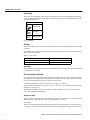
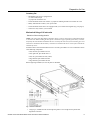
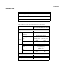
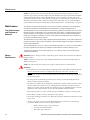
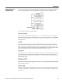
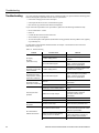
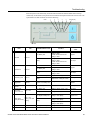
Chloride Linear Plus Rack-Mount UPS User Instruction Manual
IMPORTANT SAFETY INSTRUCTIONS
SAVE THESE INSTRUCTIONS.
This manual contains important instructions for models:
• LP061XHR
• LP101XHR
• LPBP100-2
Follow these instructions during the unpacking, installation, and maintenance of the UPS. If you have a
problem with the UPS, please refer to this manual before calling technical services.
Chloride North Americ a
27944 North Bradley Road
Libertyville, IL 60048-9700
USA
Chloride Europe
George Curl Way
Southampton, Hampshire
SO18 2RY
United Kingdom
T (847) 816-6000
(800) 327-8801
F (847) 680-5124
T +44 (0) 2380 610311
F +44 (0) 2380 649994
www.chloride-na.com
Entire contents copyright © 2007 Chloride Group PLC. All rights reserved. Reproduction in whole or in part without permission is prohibited. All information
subject to change without notice.
913-610 @ Rev. C
10/07
Introduction ......................................................................................................................................................................................... 1
Registering Your UPS ......................................................................................................................................................................... 1
Technical Support ............................................................................................................................................................................... 1
FCC Compliance ................................................................................................................................................................................. 1
Safety Compliance .............................................................................................................................................................................. 1
Safety ................................................................................................................................................................................................... 1
Intended Use ................................................................................................................................................................................ 1
Safety Notices .............................................................................................................................................................................. 2
Emergency ................................................................................................................................................................................... 3
Leakage Currents ......................................................................................................................................................................... 3
Radio Interference ........................................................................................................................................................................ 3
Batteries ....................................................................................................................................................................................... 3
Repackaging ................................................................................................................................................................................. 3
Notes Regarding the EU Declaration of Conformity ................................................................................................................... 3
About the Operating Instructions ........................................................................................................................................................ 4
Device Overview .......................................................................................................................................................................... 4
Symbols ........................................................................................................................................................................................ 4
Documentation Structure ............................................................................................................................................................. 4
Preparation for Use .............................................................................................................................................................................. 4
Delivery and Storage .................................................................................................................................................................... 4
Installation ........................................................................................................................................................................................... 7
Electrical Preparations ................................................................................................................................................................. 7
Installation Data ........................................................................................................................................................................... 8
Cable Sizes and Current ............................................................................................................................................................... 9
Neutral Connection .................................................................................................................................................................... 10
External Protection and Isolating Devices ................................................................................................................................. 10
Installation of Differential Protection Devices .......................................................................................................................... 10
Terminal Blocks for UPS ........................................................................................................................................................... 11
Connecting Mains ...................................................................................................................................................................... 12
Connecting Load Cables ............................................................................................................................................................ 12
External Battery Connection ...................................................................................................................................................... 12
Auxiliary Backfeed Protection ................................................................................................................................................... 13
Operation .................................................................................................................................................................................... 13
Reset ........................................................................................................................................................................................... 13
Operating the Device ......................................................................................................................................................................... 13
UPS Start-Up Procedure ............................................................................................................................................................ 14
UPS Shutdown Procedure .......................................................................................................................................................... 15
Functional Test ........................................................................................................................................................................... 15
Indication and Operating Elements Linear Plus Rack-mount .................................................................................................... 15
Indication and Operating Elements ............................................................................................................................................ 16
Remote Power Off (RPO) .......................................................................................................................................................... 18
Emergency Power Off (ESD hardwired) ................................................................................................................................... 19
Paralleling UPS Devices ............................................................................................................................................................ 19
Designing a Parallel System ...................................................................................................................................................... 19
Parallel System, Installation and Operating ............................................................................................................................... 19
Maintenance ...................................................................................................................................................................................... 21
Battery Replacement .................................................................................................................................................................. 21
Storage ....................................................................................................................................................................................... 22
Cleaning ..................................................................................................................................................................................... 22
Interfaces ........................................................................................................................................................................................... 22
Serial Interface COM 3 .............................................................................................................................................................. 22
Optional Isolated Contacts Card ................................................................................................................................................ 24
Troubleshooting ................................................................................................................................................................................ 25
i
ii
Introduction
Introduction
Thank you for selecting this uninterruptible power supply (UPS). Chloride’s Linear Plus Rack-mount
Series UPS offers the most reliable protection from the harmful effects of electrical line disturbances for
your computing and communications equipment. Chloride’s ISO 9001 certification represents our
commitment to building world-class products. We take pride in every unit that leaves our facility.
Registering
Your UPS
To ensure that your Linear Plus Rack-Mount Series UPS model and serial number are registered, complete
and mail the enclosed postage-paid warranty card.
Technical
Support
Chloride offers 24-hour technical support. To contact Chloride Service:
• North America: (847) 816-6000, option 3
or toll free (800) 327-8801, option 3.
Please check with Chloride Service for assistance ordering, replacing, or disposing of batteries. Please
check with Chloride Service before attempting to repair or return any Chloride product. If a Chloride UPS
needs repair or replacement, Service will issue a Return Material Authorization (RMA) number along
with instructions on how to return the UPS.
FCC
Compliance
ATTENTION: Changes or modifications to this unit not expressly approved by the party responsible or
in FCC compliance could void the user’s authority to operate the equipment.
This equipment was tested and complies with the limits for a Class A digital device, pursuant to Part 15
of FCC Rules. These limits are designed to provide reasonable protection against harmful interference
when the UPS is operating in a commercial environment. The UPS generates, uses, and can radiate radio
frequency energy. If installation and use is not in accordance with the instruction manual, it may cause
harmful interference to radio communications.
ATTENTION: Operation of this equipment in a residential area may cause harmful radio
communications interference. The user is responsible for correcting the interference.
Safety
Compliance
UL listing to UL1778
TUV compliance to EN62040-1
CE
Safety
Intended Use
This device serves as an uninterruptible power supply for connected loads. The device is in compliance
with all relevant safety regulations concerning information technology equipment, including electronic
machines for use in an office environment.
Depending on the type and rating of UPS device, certain configurations of battery extensions must be
connected. These battery extensions may only be connected to the compatible basic UPS unit.
This system, henceforward the “unit”, serves as uninterruptible power supply for connected loads,
available for use in 19-inch racks. The 6 kVA and 10 kVA must be operated with at least one rack-mount
battery extension. These battery extensions may only be connected electrically with the corresponding
base UPS unit.
WARNING: Chloride considers the safety of personnel to be of paramount importance. For this reason
it is essential that procedures relating to safety be studied before commencing work, and properly adhered
to thereafter.
1
Chloride Linear Plus Series Rack-mount UPS User Instruction Manual
Safety
• The User or Operator may intervene in the operation of the UPS provided that the instructions laid
out in “Batteries” on page 3, “Control Panel for the Linear Plus Rack-mount” on page 16 and
“Indication and Operating Elements Linear Plus Rack-mount” on page 15 are strictly adhered to.
• The “Installation” of the UPS, described in “Installation” on page 7, may only be carried out by
qualified technical personnel.
• Even when all switches and interrupters are open, hazardous voltages are present within the UPS; any
operation that requires protection panels to be opened and/or removed must be carried out by Chloride
authorized technical personnel only.
The Linear Plus Rack-mount Series UPS listed in Table 1 on page 4, with a mounting height of 3 U (1 U
= 1.75” (44.45 mm)], are designed for horizontal installation in 19-inch racks of industrial standard.
Safety Notices
WARNING: Carefully read the following safety notices! Failure to observe the instructions may
endanger your life, your health, the reliability of your device or the security of your data.
• Transport the unit only in suitable packaging (protected against jolts and shocks).
• If the equipment is moved from a cold environment to the operating room, condensation may occur.
Before you switch on the equipment it must be absolutely dry. An acclimatization period of at least
two hours is required.
• The equipment must be installed in accordance with the environmental conditions specified
in “Environmental conditions” on page 5 and in Table 3 on page 8.
• Even with all buttons in “OFF” (see chapter “Control Panel for the Linear Plus Rack-mount” on page
16) the device (UPS) is not isolated from the mains. To isolate completely from the mains, the power
cables must be disconnected.
• In case of interruption of the mains voltage, the integrated battery maintains the power supply to the
user equipment.
• Lay all cables so that nobody can stand on them or trip over them. When connecting the device to the
power supply, follow the instructions in the chapter “Installation” on page 7.
• Make sure that no objects (e.g. pins, necklaces, paper clips, etc.) inside the device.
• In emergencies (e.g. damaged case, controls or power cables, penetration of liquids or foreign matter)
switch off the device and contact the appropriate customer service representative.
• Do not connect equipment that will overload the UPS (e.g. laser printers or vacuum cleaners) or
demand DC-current (e.g. half-wave rectifiers).
• When cleaning the unit, follow the instructions in the chapter “Maintenance” on page 21.
• The sum of the leakage currents (protective conductor current) of the UPS and the connected devices
exceeds 3.5 mA for all ratings of the UPS. Earth connection is essential before connecting supply.
• Data transmission lines should not be connected or disconnected during a thunderstorm.
• Emergency Power Off (EPO) input is located on the rear of the unit (see Fig. 5 on page 11). When this
connection is open, the logic circuit will immediately shut down the UPS output.
• In order that the wiring installation safety comply to the European Harmonized Document
HD384-4-46 S1, an Emergency Switching Device (E.S.D.) shall be fitted downstream of the UPS.
• When mounting the unit into a rack, it has to be hooked on both sides and the front plate of the unit
has to be fixed to the rack by screws. The unit has to be fixed in horizontal position.
• Do not connect:
- more than 5external batteries to the Linear Plus Rack-mount 6 KVA.
- more than 5 external batteries to the Linear Plus Rack-mount 10 KVA.
• The vents for air intake and outlet at the front and rear side must not be obstructed.
• Linear Plus Rack-mount UPSs are equipped with additional safety relays, that protect the input
terminals in special cases.
Chloride Linear Plus Series Rack-mount UPS User Instruction Manual
2
Safety
Emergency
WARNING: The supply to the load may be interrupted by opening all the switches.
WARNING: DO NOT USE WATER to extinguish any fires that may occur in the area in which the UPS
is installed.
Leakage Currents
WARNING: Connect the earth ground [protection earth (PE)] safety conductor before any other cables
are connected.
Radio Interference
Linear Plus Rack-mount is a class A product.
The UPS device may cause radio interference. Do not place it near devices which are especially
susceptible to electromagnetical interference (e.g. transmitters/receivers, radar, metal detectors, anti-theft
devices).
Batteries
Battery maintenance must be carried out by authorized personnel.
• The batteries installed in external battery cabinets may contain electrolyte. Under normal conditions
the containers are dry. A damaged battery may leak electrolyte which can be dangerous in contact with
the skin and cause irritation to the eyes. Should this happen wash the affected part with copious
amounts of water and seek immediate medical advice.
• Voltage is always present on the battery contacts.
• Even when discharged a battery has the capacity to supply a high short circuit current, which, in
addition to causing damage to the battery itself and to associated cables, may expose the operator to
the risk of burns.
• The voltage of a single cell of a single battery block is not dangerous. However a number of cells or
battery blocks, connected in series, can produce hazardous voltages.
• The battery is a “hermetic” type battery and must not be kept in storage or disuse for periods
exceeding 6 months at 68°F (20°C) without being recharged (having been charged to 100% at the
beginning of any such period). If this period is exceeded it is essential that the batteries be recharged,
which requires that the UPS be switched on. If these conditions are not respected the performance of
the battery can no longer be guaranteed. We advise recharging the batteries at least once every 4
months.
• Since new batteries often do not provide full capacity after an initial charge it may be necessary to
carry out a number of discharge/recharge cycles before optimum performance is achieved.
• In order to protect the environment batteries must be disposed of in accordance with the regulations
governing disposal of toxic and harmful waste.
Repackaging
To re-pack, proceed as follows:
1. Do not pack the equipment until at least six hours have elapsed since the last recharge.
2. Place the equipment in bags made of a material sufficiently porous to allow it to breathe (e.g. 100μm
polyethylene).
3. Do not remove air from the packaging.
Notes Regarding the
EU Declaration of
Conformity
The Linear Plus Rack-mount devices conform to the following European directives:
73/23/EEC
Directive of the council for adaptation of the legal regulations of the memberstates regarding electrical
equipment for use within specific voltage limits, modified by directive 93/68/EEC.
89/336/EEC
Directive of the council for adaptation of the legal regulations of the member states regarding
electromagnetic compatibility, modified by directive 91/263/EEC, 92/31/EEC and 93/68/EEC.
3
Chloride Linear Plus Series Rack-mount UPS User Instruction Manual
About the Operating Instructions
Conformity is established through compliance with the following standards:
• EN 62040-1-1
• EN 62040-2
Additional information regarding adherence to these directives is included in the appendices NSR and
EMC of the EU Declaration of Conformity.
If required, the EU Declaration of Conformity can be requested from Chloride.
About the
Operating
Instructions
This manual contains information regarding the installation, operation and use of the Uninterruptible
Power Supply (UPS) Linear Plus Rack-mount.
Introduction
It is advised that this User’s Manual be consulted before installation of the equipment, which operation
shall only be carried out be qualified personnel. Thereafter, it shall be kept and referred to whenever it is
necessary to carry out work on the UPS.
Device Overview
The Linear Plus Rack-mount devices are available at various nominal power ratings.
The following table provides an overview of the various versions of the device:
Table 1. Overview of UPS devices and batteries (BP = Battery Pack)
Type
Designation
Order No.
Nominal Power
Linear Plus Rack-mount 6 kVA
LP061XHR-
6000 VA
Linear Plus Rack-mount 10 kVA
LP101XHR-
10000 VA
Standard External Battery
LPBP100-2
NA
19“ rack-mount UPS
External Battery
Symbols
The following symbols are used in this handbook:
WARNING: indicates instructions which, if not observed, may endanger your life, your health, the
reliability of your device or the security of your data.
NOTE: Indicates additional information and tips.
Documentation
Structure
These instructions can be supplemented with additional sheets, describing, for example, specific
extensions, options or device status.
Preparation for
Use
Delivery
Delivery and Storage
The goods have been checked thoroughly before dispatch. On receipt check the packaging and ensure that
the contents are undamaged. Any damage or missing parts must be reported to the supplier within 8 days
of delivery.
Chloride Linear Plus Series Rack-mount UPS User Instruction Manual
4
Preparation for Use
Unpacking
The utmost care shall be taken when removing the packaging in order to avoid damaging the equipment.
Check all packaging materials to ensure that no items are discarded. Remove the packaging following the
sequence illustrated in Fig. 1.
TOOLS KIT
PALLET JACK
SCISSORS
SCREWDRIVER
Fig. 1: Unpacking
Storage
If it is not intended that the UPS be used immediately upon delivery, attention shall be paid to the storage
conditions.
If the batteries or the equipment are to be stored, they must be kept in a clean, dry environment and away
from extremes of temperature.
Table 2. Storage data
Temperature limits - Batteries ONLY
+32°F to +104°F (0°C to +40°C)
Temperature limits - UPS without batteries
-13°F to +131°F (-25°C to +55°C)
Relative humidity
from 10% to 90%
Handling
The equipment must be kept upright at all times and handled with care, damage may be caused if dropped
or subjected to severe impact.
Environmental conditions
The Linear Plus Rack-mount UPS must be installed horizontally, and in an area protected from extremes
of temperature, water and humidity and the presence of conductive powder or dust. (See Table 3 on page
8). Do not stack units and do not place any objects on top of a unit.
The functional temperature range of the UPS is 32°F to 104°F (0°C to 40°C).
The ideal ambient temperature range is 59°F to 77°F (15°C to 25°C). The maximum ambient operating
temperature is 104°F (40°C).
The battery life is defined at 68°F (20°C).Operation of the equipment above 77°F (25°C) reduces the
service life of the batteries dramatically.
Access to area
The area must have sufficient space for the installation operation to be carried out. Access doors must be
sufficiently large to permit passage of the unit (See “Installation” on page 7).
Rack loading
Taking into consideration the weight of the Linear Plus Rack-mount UPS/batteries as reported in Table 5
on page 9, it is necessary that the chosen cabinet be capable of supporting the weight of the unit / batteries.
5
Chloride Linear Plus Series Rack-mount UPS User Instruction Manual
Preparation for Use
Inventory list
• Parallelable UPS types are equipped with
(1) control cable, 25-pin
(1) jumper for terminals S1-S2
• Linear Plus Rack-mount UPS contains (1) jumper for disabling the EPO circuit when not in use.
• Battery cabinets/racks contain (1) DC-power cable
• Linear Plus Rack-mount devices are equipped with (1) set of rails and rail guides (Fig. 2 on page 6)
• UPS devices only contain (1) user manual
Mechanical fixing of 19 inch units
Selection of the mounting location
NOTE: The Linear Plus Rack-Mount UPS and its battery racks are designed to be mounted horizontal
in 19-inch racks. When installing the units please consider the weight, especially of the battery extension.
Preferably the units should be installed in the lower section of the rack. UPS systems consisting of several
units must be installed so that the battery extensions are mounted in the lower section of the rack with the
UPS directly above.
Included in each Linear Plus Rack-Mount carton is a rail kit, part number 301-170. The Rail Kit consists
of the following components:
• Rail, left front, part number 203-710
• Rail, right front, part number 203-711
• Rail, rear, part number 203-645 (2 each)
• Bag, hardware part number 360-020
• Bag, hardware, part number 360-021
Before beginning installation, be sure all parts are identified.
Fig. 2: Rack Kit Installation
1. Using Fig. 2, assemble the left rail and right rail guides. Leave enough slack to permit final
alignments in the rack.
Chloride Linear Plus Series Rack-mount UPS User Instruction Manual
6
Installation
2. Position the left and right rail guides in the four-post rack and tighten all fasteners.
CAUTION: The rail guide for the lowest battery cabinet should be installed first at the lowest position in
the rack. Once the first battery is installed, then subsequent battery rail guides should be installed above.
The final rail guide assembly, located above the last battery cabinet, should support the UPS cabinet at
the top.
3. Using Fig. 3, assemble the mounting rails to the body of the UPS or battery extension.
4. Slide the Linear Plus battery chassis, with its left and right hand channels attached, onto the rail guide
until the front of the chassis is in contact with the front of the rail guide.
5. Fasten the chassis to the rack as shown in usig the screws (D) and flat washers (E).
Repeat for each subsequent chassis.
When all of the chassis units are securely in the rack continue with the electrical installation. See
“Electrical Preparations” on page 7.
The units must be secured in the rack on both sides. When using the UPS attached mounting rails (see
Fig. 3 below), the single unit can easily be inserted into a 3 U mounting space. In order to secure the unit
in the horizontal position, the front-plate has to be secured to the 19-inch rack at the indicated points on
both sides of the unit. It is not permissible to secure the unit only at the front-plate. This may damage the
unit and/or other mounted units.
Front plate
Mounting rail of UPS or battery extension on the right
side. A separate second rail is
mounted on the left side
Fig. 3: Mounting the rails to the body of the UPS or battery extension
Installation
Electrical
Preparations
During installation the input source must be isolated and secured against the possibility of being
reconnected. The Input miniature circuit breaker located at the rear of the UPS and both circuit breaker
poles of the battery cabinet(s) must be in “OFF” position. Connect the UPS and battery cabinet(s)
according to these instruction.
NOTE: It must be ensured that the live input source cannot accidentally be connected to the UPS during
installation.
WARNING: Installation may be carried out only by qualified technicians and in conformity with the
applicable safety standards.
WARNING: Electrical shock hazard: Even when the unit is disconnected from the mains, hazardous
voltage may still be supplied by the battery. Both circuit breaker poles should, therefore, be disconnected
before carrying out maintenance or installation work inside the UPS.
For electrical installation, the nominal current rating of the source must be observed. The UPS must be
connected to a suitably rated circuit.
7
Chloride Linear Plus Series Rack-mount UPS User Instruction Manual
Installation
Installation Data
Table 3. Environment data
Ambient temperature
+32°F to +104°F (0 °C to +40 °C)
Relative humidity (w/o condensing at 20°C)
90%
Max. altitude (w/o derating)
1000 m a.s.l.
Cable inlet
bottom at the rear side
Air inlet
front
Air outlet
rear
Table 4. Electrical data Linear Plus Rack-mount 6 kVA/10 kVA
UPS-TYPE
Linear Plus
Linear Plus
Rack-mount 6 kVA Rack-mount 10 kVA
Electrical Data
Rating
Input
Battery
external
6 kVA
Voltage
208, 220, 230, 240 VAC, 1 phase
Frequency
50/60Hz ± 5%,
automatic frequency sensing
Current @ 208 VAC
29 A
48 A
External battery
packs only (1 to 5
packs)
External battery
packs only (1 to 5
packs)
Typea
Voltage/Ah
Type
Voltage
Frequency with mains
control
Output
10 kVA
240V/ 20x (12V/8 Ah)
Yuasa Rew 45-12FR
208, 220, 230, 240V ± 2%
see input frequency
Frequency with internal
clock
Nominal current at
cos ϕ = 0.7 and 208 V
50/60Hz ± 0.5%
28.8 A
48 A
General
Over voltage category
Protection class
Cooling
II
IP 20
Ventilator
a. use battery type for replacement purpose also. No other type permitted
Chloride Linear Plus Series Rack-mount UPS User Instruction Manual
8
Installation
inearP
Table 5. Mechanical data Linear Plus Rack-mount 6 kVA/10 kVA
UPS-TYPE
Linear Plus
Rack-mount 6 kVA
Linear Plus
Rack-mount 10 kVA
53 (24)
57 (26)
Mechanical Data
Net Weight - lbs (kg)
Dimensions - in (mm)
UPS
Width
19 (482.6)
Height
5.125 (130)
Depth
28.1 (715)
Dimensions - in (mm)
Body dimensions
Width
16.1 (410)
Height
5.125 (130) (3 U)
Depth
26 (660)
Type
Battery
extensions
LPBP100-2
Weight - lbs (kg)
152 (69)
Dimensions - in (mm)
Widtth
Battery
dimensions
(16.1) 410
Height
5.125 (130) (3 U)
Depth
Cable Sizes and
Current
26 (660)
26 (660)
The following table indicates the recommended sizes of conductors in accordance with the NEC®. (Air
temperature surrounding the conduits not greater than 104°F (40°C).)
NOTE: Cable sizes are suggested and based on standard configurations. Installers should verify correct
conductor sizes pursuant to NEC® and/or state or local codes. If the installation requires long conductor
runs, consult NEC® and/or state or local codes to account for electrical losses.
Table 6. Cable Sizes
6 kVA
Term ID
MAIN
OUTPUT
Description
10 kVA
(°C)
main
wire
gauge
(awg
term
torque
(in-lbs)
min wire
temp (°C)*
main wire
gauge
(awg
term
torque
(in-lbs)
min wire
temp
*
L/N
Line 1 (Main)
8
22
90
6
22
90
L
Line 2 (Main)
8
22
90
6
22
90
Chassis Ground
**
22
90
**
22
90
L/N
Output Term 1
10
22
90
6
22
90
L
Output Term 2
10
22
90
6
22
90
Output Term 3
10
22
90
6
22
90
* Use insulated copper wire rated 90°C minimum.
** Must be no smaller than wire connected to mains L and L/N.
NOTE: For installation per IEC regulations: If installing units per regulations IEC-287 and DIN VDE 0298, 6 kVA model
should be wired (inputs and outputs) with 6 mm2 cable torqued to 2.5nt-m; and 10kVA model (inputs and outputs) should be
wired with 10 mm2 cable torqued to 2.5nt-m. (Based on 90°C cable and ambient of 40°C)
WARNING: Particularly sensitive equipment may be susceptible to interference; in order to prevent this,
it is suggested that input, output and any external battery cables to the UPS be housed in earthed, metal
9
Chloride Linear Plus Series Rack-mount UPS User Instruction Manual
Installation
conduits or that shielded cables be used. Routing of cables (e.g. power supplies, communication or data
lines) to other equipment, should be kept separate from that of UPS cables.
Neutral Connection
The installation of the UPS does not affect the existing Neutral system.
The Neutral system may be affected if the UPS is operating with the Neutral switched upstream.
External Protection
and Isolating
Devices
WARNING: A disconnect switch shall be provided by others for AC input/output circuit. To reduce the
risk of fire, connect only to a circuit provided with branch circuit over current protection for Table 7
Amperes rating in accordance with the National Electric Code, ANSI/NFPA 70.
The following table indicates the protection devices (circuit breakers and fuses) which must be installed
by the installing personnel for protection of both the cables and the equipment.
Table 7. Fuses or circuit breakers
Linear Plus Rack-mount
6 kVA
Linear Plus Rack-mount
10 kVA
Fuse / A
40 A
60 A
Circuit breaker / A
40 A
60 A
Circuit breaker
30 A
50 A
UPS Type
Input
Output
NOTE: The external battery cabinet shall be located adjacent to the UPS. When such an option is
supplied by Chloride it comes complete with protection devices and correctly-sized cables. When batteries
are sourced from other suppliers it is advised that Chloride be contacted for correct sizing of protection
devices and interconnection cables.
Installation of
Differential
Protection Devices
Fig. 4 illustrates the method of installing differential breakers.
To avoid spurious operation, differential protection devices must:
• be rated at differential current NOT LESS THAN 100 mA
• be a SELECTIVE type (delayed intervention)
• be Type A
Output
D1
External Battery Pack
Fig. 4: Standard configuration
Chloride Linear Plus Series Rack-mount UPS User Instruction Manual
10
Installation
Terminal Blocks for
UPS
The following figures show the units with the external battery extension.
To connect the external battery to the UPS, plug the battery cable (16) into the socket (9) and into a battery
extension socket (13).
12
14
|
o
16
13
15
16
Fig. 5: Rear View Linear Plus Rack-mount UPS (top), Battery (center), and Cable (bottom)
Legend:
1. Output socket(s) IEC 320 - C19
11. Mains connection, Terminal Block
2. 2 Output circuit breaker (for plugged outlets)
12. Battery socket for battery connection cable to
UPS
3. Input miniature circuit breaker
13. Battery extension cable socket. Connected to
UPS or another battery extension
4. Fan
5. Cover of parallel port
6. Communication Slot (Option)
7. ESD Contacts (control)
7a. ESD Contacts, hardwired
14. Battery extension circuit breaker
15. Earth connection
16. Battery extension connection cable
9. Battery socket
17. S1, S2: Paralleling terminals (bridged 10
mm2 if UPS works in single block mode,
open if UPS in parallel operation)
10. Strain relief
18. Terminals for backfeed control
8. UPS interface COM 3
NOTE: Each external battery cabinet is supplied with one battery connection cable (16). The first
11
Chloride Linear Plus Series Rack-mount UPS User Instruction Manual
Installation
extension is connected to the battery connection the UPS (9), each subsequent extension is connected by
means of the battery extension connection cables (16). The cables are designed to be
non-interchangeable, because the sockets (13) are coded.
Connecting Mains
Connect the mains supply to the input terminals of the UPS (see Fig. 5 on page 11 and Table 6 on page 9).
Connecting parallel UPS configurations: refer to chapter “Paralleling UPS Devices” on page 19.
Connecting Load
Cables
1. Open UPS input breaker.
2. Remove terminal area safety cover.
3. Connect loads to “Output” terminals (see Fig. 5 on page 11 and Table 6 on page 9).
4. Connect mains to the corresponding input terminals (see Fig. 5 on page 11 and Table 6 on page 9).
Preparing single mode / parallel mode:
• If UPS is to be operated as single unit connect a 6 awg (10 mm2) jumper between S1 and S2.
• If UPS is to be operated as parallel unit ensure that no jumper is connected between S1 / S2.
External Battery
Connection
WARNING:
•The batteries installed in external battery cabinet may contain electrolyte. Under normal conditions the
containers are dry. A damaged battery may leak electrolyte which can be dangerous in contact with the
skin and cause irritation to the eyes. Should this happen wash the affected part with copious amounts of
water and seek immediate medical advice.
•Do not open or damage batteries. The released electrolyte is toxic.
•Voltage is always present on the battery contacts.
•Even when discharged a battery has the capacity to supply a high short circuit current, which, in addition
to causing damage to the battery itself and to associated cables, may expose the operator to the risk of
burns. The following precautions should be observed when working on batteries:
• Remove watches, rings or other metal objects.
• Use tools with insulated handles.
•The voltage of a single cell of a single battery block is not dangerous. However a number of cells or
battery blocks, connected in series, can produce hazardous voltages.
•The accumulator is a “hermetic” type battery and must not be kept in storage or disuse for periods
exceeding 6 months at 68°F (20 °C) without being recharged (having been charged to 100% at the
beginning of any such period). If this period is exceeded it is essential that the batteries be recharged,
which requires that the UPS be switched on. If these conditions are not respected the performance of the
battery can no longer be guaranteed. We advise recharging the batteries at least once every 4 months.
•Since new batteries often do not provide full capacity after an initial charge it may be necessary to carry
out a number of discharge/recharge cycles before optimum performance is achieved.
•When replacing batteries, replace with the same type and number of batteries and battery packs.
•In order to protect the environment batteries must be disposed of in accordance with the regulations
governing disposal of toxic and harmful waste.
•Do not dispose of batteries in a fire. The batteries may explode.
Before Connecting the UPS and the external battery cabinet, check to see that the battery breaker is in the
“OFF” position.
The battery connection cable plug is keyed to the receptacles on the UPS and battery cabinet. Insure that
the plug notch is correctly aligned with the receptacle guide when connecting the components together.
Chloride Linear Plus Series Rack-mount UPS User Instruction Manual
12
Operating the Device
Auxiliary Backfeed
Protection
To support protection against UPS backfeeding logic is integrated into Linear Plus Rack-mount.
Using backfeed protection
On customers side an additional magnetic contactor (MC) may be provided. The magnetic contactor must
be able to carry the UPS input current (see tableTable 4, “Electrical data Linear Plus Rack-mount 6 kVA/
10 kVA,” on page 8).
The MC has to be installed in the common input supply path. Cabling of the backfeed terminals contains
a jumper and two cables to the optional magnetic contactor.
Not using backfeed protection
For cabling the backfeed terminal board, please follow Fig. 6.
The factory setting of the backfeed terminal board, located on the UPS rear side, is shown there .
P in s
M a
M a
M C
M C
M a
in s
in s
/c o
/c o
in s
2 /L
2 /N
il, o u t
il, in
2 /N , s e n s o r
Fig. 6: Backfeed terminal board, factory setting
Operation
If bypass thyristor is shorted (short circuit) and UPS runs in double conversion mode (online) the
following steps follow:
• the backfeed detection circuit activates, backfeed relay opens.
• Press the “o” button to acknowledge the fault.
Reset
To reset the backfeed logic the UPS input circuit breaker/battery circuit breaker must be switched “OFF”
for 10 seconds
Operating the
Device
Block diagram Linear Plus Rack-mount
Normal and Safe
Operating
Linear Plus Rack-mount 6 kVA and 10 kVA consists of the following main components
• mains supply
• input switch
• rectifier/booster, inverter and charger
• electronic bypass
• paralleling contactor
• RPO hardwired
• backfeed protection logic
• Battery racks are external.
13
Chloride Linear Plus Series Rack-mount UPS User Instruction Manual
Operating the Device
Automatic
bypass
Mains
Rectifier/
Booster
S
2
1
ESD
L
Mains
S
Inverter
L
LN
LN
UPS rack
Charger
Battery fuse
b lo c k _ L in + _ E _ r a c k .d s f
Battery rack
Battery fuse
Battery rack
External battery
6 k V A /1 0 k V A R A C K
Fig. 7: Overview of components Linear Plus Rack-mount 6 kVA/10 kVA
Preliminary controls
Before switching on the UPS and supplying the load the following shall be observed:
• Ensure that the ventilation grilles are unobstructed.
• Ensure the ground (earth) connection is in place.
• Ensure that the load switches are in the OFF (0) position.
• Ensure that all UPS rear panel switches are in the OFF (0) position.
WARNING: As soon as the UPS is connected to the AC mains, the output sockets are live, even if the UPS
is not yet switched on via the front panel switch.
1. Switch ON the mains supply to the UPS Linear Plus Rack-mount.
When connected to the mains, the “LINE” and “BYPASS” LEDs on the control panel are illuminated
and the UPS starts recharging the connected (external) batteries immediately. Before using the
device, the batteries should be recharged for a period of 8 hours. The UPS may be used immediately,
even without charging, but will not be able to provide the specified autonomy.
2. Once recharging has been completed the UPS is ready for use, follow the UPS Start-Up Procedure see “UPS Start-Up Procedure” on page 14.
WARNING: Do not connect any devices that may overload the UPS or draw DC current.
NOTE: If these instructions are not observed correctly, problems may be experienced with the electrical
supply.
UPS Start-Up
Procedure
1. Ensure all the mains switches and circuit breakers upstream of the UPS are closed.
2. Ensure batteries are connected.
3. Switch the battery breaker to the closed ( | ) position.
4. Switch input breaker to “ON ’position ( | ).
5. The unit will go through a self-test. Wait for the yellow BYPASS LED to illuminate (approximately
15 seconds).
Chloride Linear Plus Series Rack-mount UPS User Instruction Manual
14
Operating the Device
6. Close any external switches connecting the load (if present).
7. Press the button
on the UPS control panel for a minimum of 1 second to switch on the inverter
(see “Control Panel for the Linear Plus Rack-mount” on page 16).
In addition to the “LINE” and “BYPASS” LEDs the “LOAD” LED and “BATTERY” LED is now
illuminated. After a few seconds the “INVERTER” LED is illuminated and the “BYPASS” LED is
extinguished. The UPS is now in ON-LINE operation.
UPS Shutdown
Procedure
NOTE: Carrying out this procedure will interrupt the supply to the load.
1. Press the button
on the UPS control panel for a minimum of 1 second to switch off the inverter.
2. Open any external switches connecting the load (if present).
3. Switch input breaker to position (0) OFF.
4. Switch off the battery breaker. to the open (O) position.
5. Ensure all mains switches and circuit breakers upstream of the UPS are open.
6. Ensure that all LEDs on the control panel are extinguished. The UPS is now completely shutdown.
Functional Test
NOTE: Supply to the load is not guaranteed during this test, it should not be carried out if a critical load
is connected to the UPS.
It is possible to carry out a functional test of the UPS to ensure that the load is still supplied in the event
of a mains failure.
Simulate a mains failure by interrupting the mains supply to the UPS. If the UPS is operating correctly
and the batteries are fully charged, an acoustic signal at intervals of 4 seconds will be heard and the “ON”
LED indication “MAINS “indicator (6) at the UPS will be extinguished. Once the interval between the
acoustic signals has decreased to 1 second, the UPS will continue to supply energy for a maximum of 3
more minutes, after which it will be automatically switched off.
The load will be supplied from the batteries during the specified emergency supply period. If this is not
the case, please consult chapter “Troubleshooting” on page 25”.
Restore the UPS mains supply. The UPS is ready for operation. Please note, that the batteries have to be
recharged before the complete emergency supply period is again available.
NOTE: The unit indicates an alarm condition, when the battery is not connected.
Canceling the battery alarm
1. To cancel the alarm, connect the battery and close the battery breaker.
2. Switch the unit to online mode by pushing the button
.
The unit checks the battery voltage (a beep is heard) once more and stays in bypass till a constant battery
voltage is present.
Battery maintenance must be carried out by authorized personnel observing the necessary precautions.
Parallel operation
Please refer to chapter “Paralleling UPS Devices” on page 19
Indication and
Operating Elements
Linear Plus
Rack-mount
15
NOTE: To effect any action, the buttons must be pressed for at least 1 second! (Acceptance of the input
is confirmed acoustically)
The following is an explanation of the symbols printed on the front panel of the UPS:
Chloride Linear Plus Series Rack-mount UPS User Instruction Manual
Operating the Device
Indication and
Operating Elements
Control Panel for the Linear Plus Rack-mount
4
7
6
2
1
3
5
The OVERLOAD indicator, red, (1) illuminates if the UPS is overloaded.
The LOAD LED strip (2) displays the load status of the UPS. See Table 8 on page 17 for details.
The BYPASS indicator, yellow, (3) illuminates when the UPS delivers voltage supplied from the mains
supply via the bypass.
The INVERTER indicator, green, (4) illuminates when the inverter is running.
The BATTERY LED chain, green, (5) indicates the charging state of the battery (normal operation). See
Table 9 on page 17 for details.
The MAINS indicator, green, (6) illuminates when normal mains voltage is present at the UPS input.
The ALARM indicator, red, (7) illuminates to indicate a UPS fault. An acoustical warning signal is
activated simultaneously; this signal is reset when the UPS is switched off.
The
button switches the inverter Off and the bypass On.
The
button switches the inverter On (bypass Off).
The inverter is activated by pressing the
button. Following a delay time of approximately 5 seconds,
the BYPASS indicator extinguishes and the INVERTER indicator illuminates.
Pressing the
present.
LOAD
button, blocks the inverter and switches the system to bypass. UPS output voltage is
BYPASS
INVERTER
BATTERY
MAINS
ALARM
!
Fig. 8: Symbols on the control panel of the UPS Linear Plus Rack-mount
The UPS indicates, by acoustic (buzz) and optical (LED) alarms, that a mains failure has occurred and is
still present. Different procedures, described below, may be followed to interrupt work in case of a
persistent mains failure.
Which of the procedures is applied depends, primarily, on the time required to close the program safely
and - if necessary - for an organized shut down of the operating system.
For example, work on a PC, which is individually supplied by the UPS, may be continued until the battery
nears minimum charge level. The buzzer indicates the mains failure periodically (every 4 seconds) and,
when minimum charge level is neared, once a second. This procedure is not often adopted. Although
battery recharge starts immediately when the mains is re-established, it can take several hours to recharge
the battery fully.
Chloride Linear Plus Series Rack-mount UPS User Instruction Manual
16
Operating the Device
The situation can better be analyzed by using the UPS load LEDs, which indicate the remaining autonomy
for a constant load. The following table shows the approximate autonomies in case of a fully charged
battery at the beginning of the mains failure.
Table 8. Backup time according to load indication (standard devices with batteries integrated)
load in %
Overload
load
6 kVA/10 kVA
LED Color
>105
red
95-105
6 min /5 min
yellow
75-95
9 min
green
55-75
17 min
green
30-55
31 min
green
1-30
60 min
green
The current battery capacity can be read from the LED chain BATTERY (see table below).
Table 9. Battery capacity according to LED chain “battery”
Battery capacity in %
LED Color
1-35
green
35-55
green
55-75
green
75-95
green
95-100
green
The most reliable method, however, is the use of either MopUPS® Professional UPS software or a
ManageUPS® network adapter. With these tools, the projected remaining battery capacity is indicated
both before and during a mains failures. Furthermore, shutdown procedures can be automated. Depending
on the application program, operating system and computer hardware, it can be ensured that in the event
of a mains failure the application programs are automatically closed, the subscribers logged in at the
server are logged out, data is stored, and the operating systems are shut down. For further information
please refer to our publication about the Chloride connectivity solutions.
Once the mains voltage returns, the UPS will restart in the preset mode. Depending on the installed
software, the computer’s status before the mains failure can be re-established.
In the event of overload or internal failure, the load is transferred to the mains via an automatic bypass,
without interruption. As soon as normal conditions are re-established, the unit switches automatically to
the inverter.
Operating modes Linear Plus Rack-mount
The UPS has three different operating modes when it is switched on.
Normal operation (mains supply present)
Fig. 9: UPS Control Panel: “Normal Operation”
17
Chloride Linear Plus Series Rack-mount UPS User Instruction Manual
Operating the Device
The loads are supplied directly from mains via the inverter. Loads are protected against mains failures and
disturbances.
Battery operation (mains failure)
Fig. 10: UPS Control Panel: “Battery Operation”
In the event of a mains failure, the inverter supplies the loads without interruption; the power is supplied
by the battery.
In this operating mode, an acoustical sound is emitted at intervals of approximately 4 seconds. If the
minimum power level of the battery is reached, the signal is emitted once a second.
Bypass operation (overload > 100%, < 150%),for
Fig. 11: UPS Control Panel: BYPASS Operation
In the event of an overload between 105% and 150% of rated capacity, the device switches to bypass and
the inverter is blocked. Power is supplied by the mains supply.
This is not a normal operating state. If the mains supply fails, the loads will no longer be supplied (no UPS
operation).
NOTE: For sustained overloads > 130% of capacity, the output will be disconnected within one hour to
protect the circuitry from overheating.
Parallel operation
Refer to chapter “Paralleling UPS Devices” on page 19.
Remote Power Off
(RPO)
For reasons of safety it is required that UPS Emergency Power Off be effected by removing the
connections between the RPO terminals located on the rear of the UPS next to the Interface COM 3
connector Fig. 5 on page 11 and connecting a switch, having the characteristics of an emergency button,
closed under normal operating conditions and held open mechanically when operated. Once the
emergency condition causing the switch to open has been resolved, open all UPS switches (Input, Output
and Battery) and carry out Switch-on procedure as described above “UPS Start-Up Procedure” on page
14).
Chloride Linear Plus Series Rack-mount UPS User Instruction Manual
18
Operating the Device
Emergency Power
Off (ESD hardwired)
This Linear Plus Rack-mount UPS is equipped with separate terminals for connecting hardwired customer
protection ESD relays. See block diagram Fig. 7 on page 14 for connection details.
Paralleling UPS
Devices
A maximum of 3 Linear Plus Rack-mount UPSs can be connected in parallel. The units to be connected
in parallel must be of the same type and rating and the settings of these devices must be identical.
General
The units configured as a parallel system may use only common mains supply.
Designing a Parallel
System
When connecting mains and loads to a parallel UPS Linear Plus Rack-mount system additional
distribution has to be taken into account.
A system of 2 parallel UPS blocks can be connected directly to the distribution if the system load doesn’t
exceed the nominal power of the UPS block (configuration: half load, 2 block parallel system)
If the supported load is greater than 50% of the total paralleled UPS load, it is suggested that an external
maintenance bypass be installed.
Parallel System,
Installation and
Operating
First step
1. Ensure, that the mains supply distribution is switched “OFF”.
2. Ensure that all the mains input breakers are switched to “OFF” on all UPSs. All terminals, breakers
and plugs of UPS can be found the respective rear panels of UPS/batteries. Related figures:
see Fig. 5 on page 11.
Second step
1. Remove jumper from Parallel Terminals (S1, S2) from each UPS terminal block (each UPS).
2. Connect the input terminals of all UPS blocks to the mains distribution. See Figure 12 on page 20.
19
Chloride Linear Plus Series Rack-mount UPS User Instruction Manual
Operating the Device
3. Connect the UPS output terminals to the load distribution.
S2
S1
Mains Power
Distribution
Cb #1
UPS #1
Remove
Optional
jumper Individual Output
s1s2
Circuit Breakers
Load
Distribution
L
Cb
L/N
L
L/N
Parallel
Connector
S2
S1
Parallel
cable #1
UPS #2
L
Cb #2
L/N
Remove
jumper
s1s2
L
Cb
L/N
Parallel
Connector
S2
S1
L
Cb #3
L/N
Parallel
cable #2
UPS #3
L
L/N
Remove
jumper
s1s2
Cb
Parallel
Connector
Fig. 12: Linear Plus Parallel Diagram
Third step
1. Remove cover of the parallel port of all parallel devices for linking between the UPS
2. Use the 25 pin standard control cable (supplied with UPS) to connect from one of the parallel ports.
NOTE: Parallel UPS are connected in line, not in a circle, i.e.: 2 cables connect 3 UPS units, 1 cable
connects 2 UPS.
Fourth step
1. Close all the input breakers of all parallel UPSs.
2. Close all battery breakers on all extension battery cabinets to the “ |” position.
3. Close the mains circuit breakers to each of the UPSs.
4. The unit will initiate a self-test for approximately 15 seconds. Wait for the yellow BYPASS LED to
illuminate.
5. Press the button
on the first UPS control panel for a minimum of 1 second.
6. Repeat the UPS start-up procedure (step 5) on the second and on third UPS, if present. At this point
all the bypass indicators are extinguished. All inverter indicators illuminate indicating that all
parallel UPS inverters are running. The load is spread evenly across all the UPSs.
In addition to the “LINE” and “BYPASS” LEDs the “LOAD” LED is now illuminated. After a few
seconds the “INVERTER” LED is illuminated and the “BYPASS” LED is extinguished. The UPS is now
in ON-LINE operation. The load is spread evenly across all the UPSs.
Chloride Linear Plus Series Rack-mount UPS User Instruction Manual
20
Maintenance
NOTE: In a parallel system, on the unit that has been requested to transfer from bypass to on-line
operation (steps 4 and 5), the battery display will pulse illuminate from right to left and the load display
will pulse illuminate from left to right. This indicates the system is waiting for the other UPS system
synchronize to the first unit. It is critical that after pushing the “ |” button on the first UPS that the second/
third Unit(s) also follows within 1 minute of starting the first UPS. Otherwise, the system that did not
respond within the time allowed will shut down with a parallel fault. See “Troubleshooting” on page 25.
Maintenance
Test, Replacement
and Disposal of
Batteries
The UPS does not require maintenance by the user, however, battery maintenance is recommended in
accordance with IEEE Recommended Practice for Maintenance, Testing and Replacement of
Valve-Regulated Lead-Acid (VRLA) Batteries for Stationary Applications (IEEE Std 1188-1996). When
the batteries expire, trained battery service personnel must replace them. A certified disposal/recycling
company should carry out disposal / recycling of the UPS and / or batteries. Exhausted rechargeable
batteries are classified as “harmful toxic waste” and as such the law demands that they be disposed of /
recycled by an authorized recycling center.
The manufacturer’s service center is fully equipped to deal with such batteries, in accordance with the law
and with the greatest respect for the environment. Contact Technical Support to arrange for maintenance
and/or battery replacement.
The typical battery life cycle is 3 to 5 years, at an ambient temperature of 77°F (25°C), however battery
life is also dependent on the frequency and duration of mains failures or battery discharge cycles.
The battery test should be carried out periodically (6 to 12 months) in order to ascertain the general
condition of the batteries.
Battery
Replacement
WARNING: Prior to starting the battery replacement, please read the entire instructions for important
safety procedures.
NOTE: To obtain new battery(ies), contact Chloride Technical Services at 847-816-6000, toll free at
800-879-5011 option 3.
NOTE: The UPS cannot protect against power outages while the batteries are disconnected.
WARNING:
• External batteries can be replaced during “normal operation” of the UPS by a trained technician.
However, the batteries must not be changed when the UPS is in the status “AC Fail = On
Battery”.The UPS devices Linear Plus Rack-mount 6 and 10 kVA have no internal battery. For
these units the AC power won’t be maintained when an AC Failure occurs during replacement of
the first battery pack!
• Servicing of batteries should be performed or supervised by personnel knowledgeable about
batteries and the required precautions.
• The batteries installed in the UPS and in the external battery cabinets contain electrolyte. Under
normal conditions the containers are dry. A damaged battery may leak electrolyte that can be
dangerous in contact with the skin and cause irritation to the eyes. Should this happen, wash the
affected part with copious amounts of water and seek immediate medical attention.
• When replacing batteries, replace with the same type and number of batteries or battery packs.
• Do not dispose of batteries in a fire. The batteries may explode.
• Do not open or damage the battery cases. Released electrolyte is harmful to the skin and eyes and
may be toxic.
• A battery can present a risk of electrical shock and high short-circuit current. The following
precautions should be observed when working on batteries:
• Remove watches, rings or other metal objects
• Use tools with insulated handles
• Wear rubber gloves and boots
21
Chloride Linear Plus Series Rack-mount UPS User Instruction Manual
Interfaces
• Do not lay tools or metal parts on top of batteries
• Disconnect charging source prior to connecting or disconnecting battery terminals
• Determine if the battery in inadvertently grounded. If inadvertently grounded, remove source from
the ground. Contact with any part of a grounded battery can result in electrical shock. The
likelihood of such shock can be reduced if such grounds are removed during installation and
maintenance (applicable to equipment and remote battery supplies not having a grounded supply
circuit).
Storage
For extended storage at ambient temperature <77°F (< 25°C) the batteries should be charged for 5 hours
once every 4 months, at higher storage temperatures it is advised that this period be reduced to 2 months.
1. Connect the UPS (with attached external battery cabinets) to a mains outlet socket having an earth
connection or install fixed connections (in accordance with chapter “Installation” on page 7) to an
appropriate source.
2. Switch on the input miniature circuit breaker at the rear of the devices (UPS and external battery
cabinet) in the case of fixed connections.
3. After 5 hours, unplug from the mains supply or switch off the input miniature circuit breaker of the
UPS in case of fixed connections, and switch off the circuit breaker of the external battery cabinet.
4. Remove the UPS and external battery cabinet connections in the opposite sequence to that described
in “Installation”.
5. Note the date recharging was carried out on the packaging of the external battery cabinet.
Cleaning
NOTE: Do not use scouring powder or plastic-dissolving solutions to clean the UPS.
1. Switch off the UPS by pressing the OFF button following the shutdown procedure and disconnect
from the mains supply.
2. Make sure that the air vents on the UPS are not obstructed.
3. Remove dust from the air vents with a vacuum cleaner.
4. Clean the outside of the UPS housing by wiping with a dry or a slightly damp cloth.
NOTE: Do not allow liquid to get inside the UPS.
Interfaces
The Linear Plus Rack-mount is equipped with a serial interface COM 3 and an interface slot COM.
These interfaces can be used for:
• Direct communication between UPS and a workstation/server
• Integration of the UPS as client into a network with centralized monitoring via a ManageUPSNET II
SNMP adapter to put in slot COM
• Transfer of operational states to external alarm systems via voltage-free contacts: with interface card
SIC to put slot COM
The necessary communication software packages and interface cables are available as options.
Serial Interface COM 3
The 9-pole SUB-D connector (pin contacts) contains RS 232 compatible signals.
Chloride Linear Plus Series Rack-mount UPS User Instruction Manual
22
Interfaces
R x D
!
T x D
"
%
&
'
$
S G N
#
C O M
3
L in e a r P lu s
Fig. 13: Serial interface COM 3
The interface COM 3 is galvanically isolated from primary UPS circuits.
SGN at pin 5
Signal ground.
RXD at pin 2 and TXD at pin 3
Receive and transmit RS 232 compatible signals.
23
Chloride Linear Plus Series Rack-mount UPS User Instruction Manual
Interfaces
Optional Isolated
Contacts Card
Below are the descriptions of the interface signals for the isolated contacts card that may be installed into
the COM slot. This optional card provides potential-free signaling contacts and a shutdown input.
Fig. 14: Isolated Contacts Card Interface Signals
INV SHUTDOWN
This input (pin 3) is enabled with a high signal (+5 V to +12 V with respect to pin 4 (0 V)) and when
enabled, switches off the UPS after a mains failure has occurred. After the mains have been reestablished,
the UPS starts again independent of this signal status. This input must be high for one (1) second before
shut off will occur.
AC FAIL
This output provides an N/O (Normally Open) contact between pins 9 and 5, and an N/C (Normally
Closed) contact between pins 8 and 5. The 9-5 contact closes when the mains voltage fails at the UPS
input or when the mains voltage falls below the lower limit for a minimum of 10 seconds. This contact
opens approximately 850 ms after the mains have been reestablished. The 8-5 contact provides a mirror
function, opening when the mains voltage fails and closing when main power returns
LOW BATT
This output provides a N/O contact between pins 6 and 5 and an N/C contact between pins 7 and 5. The
6-5 contact closes when the battery has been depleted to the point that it can only supply current for
approximately three (3) more minutes at nominal load. The 7-5 contact provides a mirror function opening
when the battery is low.
BYPASS ACTIVE
This output provides an N/O contact between pins 1 and 5. The 1-5 contact closes after switching to the
bypass mode. In the bypass mode, energy to the output of the UPS is being supplied by the mains power
and not through the inverter.
SUM ALARM
This output provides an N/O contact between pins 2 and 5. The 2-5 contact closes when one of the alarms
“AC FAIL,” “LOW BATT” or “BYPASS ACTIVE” is active or when the indication “ALARM” at the
front-panel is on.
Chloride Linear Plus Series Rack-mount UPS User Instruction Manual
24
Troubleshooting
Troubleshooting
If, in spite of the high reliability of this device, problems should occur, please check the following points
before contacting the responsible customer service representative:
• Is the mains voltage present at the UPS input?
• Is the input fuse blown or have circuit breakers tripped?
• Has UPS start up procedure been followed completely?
If you contact the responsible service representative, please have the following information ready:
• Device information = model
• Order no.
• Consult the label on the left front of the unit.
• Series number as per nameplate
• An exact description of the problem (what loads are being operated, does the problem occur regularly
or sporadically etc.)
For description of the indicators mentioned below see chapter “Control Panel for the Linear Plus
Rack-mount” on page 16.
Table 10. Troubleshooting
Problem
No display
No alarm
(UPS switched off)
Possible cause
Mains switched off
Switch on mains switch
No mains voltage present
Have mains inspected by qualified
electrician
Input circuit breaker tripped
Reset circuit breaker. If the problem
persists, contact the responsible
customer service representative.
MAINS indicator does not
illuminate, acoustic alarm No mains voltage present
active at intervals
UPS operation “Operating modes Linear
Plus Rack-mount” on page 17
MAINS indicator does not
illuminate when mains
Input circuit breaker tripped
voltage present, acoustic
alarm active at intervals
Reset circuit breaker. If the problem
persists, contact the responsible
customer service representative.
ALARM indicator
UPS error
illuminates, acoustic
alarm active continuously Overheating
Autonomy less than
specified
OVERLOAD LED
illuminates
No communication
between UPS and PC
25
Measure
Contact the responsible customer service
representative
Decrease ambient temperature
The fuse switch of the battery
extension(s) is in the “OPEN” position.
Move the fuse switch to the “ON”
position.
Batteries are not fully charged
Charge batteries and test backup time. If
the problem persists, contact the
responsible customer service
representative.
Batteries are defective
Contact customer service
Charging device is defective
Contact customer service
Overload at UPS output
Reduce load to the permissible value
Wrong serial connection cable
Check whether the correct cable has
been used (standard modem/null modem
cables are not permissible)
Interface on the PC is being used by
another process or is defective.
Check whether other software/service is
accessing the interface on the PC; try
selecting a different serial interface.
Interference on the data cable
Lay cables differently.
Chloride Linear Plus Series Rack-mount UPS User Instruction Manual
Troubleshooting
When the system works abnormally, the Fault LED will illuminate and the audible alarm will beep
continuously. In this situation, the panel LEDs will indicate which part inside the UPS is out of order. The
representations of fault conditions are listed as following:
LEDs:
1
2
3
4
5
Overload (OL)
Fault LED
Fault
1
2
BUS fault
Inverter fault
3 Overheating fault
LED
UPS Mode Before Fault
Condition
UPS Mode After
Fault
Line, Battery Test
Voltage > 450V
Voltage > 400V
+-BUS unbalanced over 40V
Voltage < 230V
Bypass
Battery
Voltage > 450V
Voltage > 400V
+-BUS unbalanced over 40V
Voltage < 230V
No output
Bypass to line
Soft start fail
Line, Battery Test
Voltage > 276V
Voltage < 140V
Battery
Voltage > 276V
Voltage < 140V
No output
Bypass, Line, Battery Test
Temperature >90degree Celsius
Bypass
Battery
Temperature >90degree Celsius
Fault & 3
Fault & 2
Fault & 1
Voltage > 292V
Bypass
No output
4
Battery over
voltage fault
Fault & 4
Bypass, Line, Battery Test
5
Battery
overload
Fault & 5
Battery, Battery test
Load > 105%
No output
Line, Battery test
Voltage < 50V & current > 20A
No output
Battery
Voltage < 50V & current > 20A
no output
Line, Bypass, Battery test
Voltage < 180V (H8)
Voltage < 185V (DSP)
Bypass, Line
Voltage < 180V (H8)
Voltage < 185V (DSP)
No output
Inverter mode,
6 output fault
Short circuit fault
7
Battery fault /
battery disconnect
Bypass
Fault, 1 & 2
Fault, 1 & 4
Battery chain LED
flashing
Battery
Voltage > 200V (H8)
Voltage > 192V (DSP)
8 Charger fault
Fault, 1 & OL
Line, Bypass, Battery test
Charge on, but battery <240V
Bypass
9 RPO active
Fault, 2 & 4
Any mode
RPO hardware active
No output
Chloride Linear Plus Series Rack-mount UPS User Instruction Manual
26
Troubleshooting
Fault
UPS Mode Before Fault
Condition
UPS Mode After
Fault
Fault, 3 & 4
Any mode
Parallel communication CAN bus
loss
No output
Fault, 2 & 4
Any mode
DSP with H8 communications error
Bypass or no
output
12 Output failure
Fault, 1 & 5
Line, Battery
Output actual power </= 800W
Bypass
13 Back feed active
Fault
Line, Battery
STS is break and cause a short
circuit from inverter top bypass
Battery
14 Parallel fault
Fault, 3 & 4
Bypass, Line
Fault of units in parallel
Units effected no
output
10 Parallel error
11
27
LED
Communications
error
Chloride Linear Plus Series Rack-mount UPS User Instruction Manual
Troubleshooting
Chloride Linear Plus Series Rack-mount UPS User Instruction Manual
28