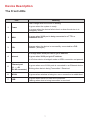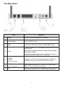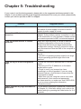
1
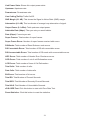
BEC 8800N
802.11n VDSL2/ ADSL2+ Broadband
Firewall Router
User Manual
Last revised on Nov. 2009
Table of Contents
Chapter 1: Introduction...................................................................... 1
Introduction to your Router........................................................... 1
Features . .................................................................................... 4
Hardware Specifications ............................................................. 5
Physical Interface . ..............................................................................5
Physical Specifications........................................................................5
Operating Environment................................................................ 5
Chapter 2: Installing the Router........................................................ 6
Package Contents........................................................................ 6
Important note for using this router.............................................. 6
Device Description....................................................................... 7
The Front LEDs....................................................................................7
The Rear Ports . ..................................................................................8
Cabling......................................................................................... 9
Chapter 3: Basic Installation .......................................................... 10
Hardware Connection................................................................ 11
Network Configuration................................................................ 12
Factory Default Settings............................................................. 18
Information from your ISP ........................................................ 19
Internet Access Configuration.................................................... 20
Configuring with your Web Browser...................................................20
Chapter 4: Configuration................................................................. 21
Status......................................................................................... 22
WAN Info............................................................................................23
Statistics.............................................................................................24
LAN................................................................................................................. 24
WAN Service................................................................................................... 25
xTM................................................................................................................. 26
xDSL................................................................................................................ 27
Route Table........................................................................................29
ARP Table..........................................................................................30
DHCP Table.......................................................................................31
System Log........................................................................................32
Configuration.............................................................................. 33
LAN - Local Area Network..................................................................34
LAN................................................................................................................. 34
WAN - Wide Area Network.................................................................36
Layer2 Interface............................................................................................... 36
WAN Service................................................................................................... 40
DSL.................................................................................................................. 48
System...............................................................................................49
Time Zone....................................................................................................... 49
Firmware Upgrade........................................................................................... 50
Backup / Restore............................................................................................. 51
Restart............................................................................................................. 52
User Management........................................................................................... 53
Firewall...............................................................................................54
IP Filtering....................................................................................................... 54
MAC Filtering................................................................................................... 58
QoS - Quality of Service....................................................................60
Queue Config.................................................................................................. 61
QoS Classification........................................................................................... 63
Virtual Server.....................................................................................65
Port Mapping................................................................................................... 66
DMZ Host........................................................................................................ 68
Advanced...........................................................................................69
Routing............................................................................................................ 69
DNS................................................................................................................. 72
Interface Grouping........................................................................................... 74
System Log Server.......................................................................................... 82
TR-069 Client.................................................................................................. 83
Diagnostics................................................................................ 84
Diagnostics........................................................................................84
Fault Management.............................................................................85
Chapter 5: Troubleshooting............................................................. 86
Appendix: Product Support & Contact........................................... 87
Chapter 1: Introduction
Introduction to your Router
Thank you for purchasing 8800N Wireless Broadband Firewall Router. Your new router is an allin-one unit that combines an VDSL2/ADSL2+/Broadband router and Ethernet network to offer
users the flexibility of multiple Internet connections. All this is offered while maintaining high-speed
broadband access via VDSL2/ADSL2+.
The BEC 8800N automatically adopts the optimal connection to deliver smooth, constant signal
reception even if obstacles are present. By using this device, you can easily enjoy high bandwidth
applications such as High Definition IPTV services without changing their home network. A robust
Firewall is also built in to provide protection against hacker attacks while the Quality of Service
feature prioritizes queues and traffic for applications such as music downloads, online gaming,
video streaming and file sharing.
1
Express Internet Access
The BEC 8800N series is compliant with worldwide VDSL/ ADSL standards, and supports download
rates of up to 100Mbps using VDSL2, 12 / 24Mbps using ADSL2 / 2+, 8Mbps using ADSL and an
upload rate of up to 50Mbps using VDSL2, 1Mbps using ADSL / ADSL2 / ADSL2+. The integrated
Annex M standard supports ADSL2 / 2+ for higher uploads by doubling the upload data rate. The
4-port 10/ 100 Mbps Fast Ethernet Switch incorporated into the BEC 8800N enables users to connect
to multiple computers or wired-Ethernet devices easily and enjoy blistering LAN transmission for
multimedia applications such as interactive gaming, IPTV video streaming and real-time audio.
Multi Network Protocol Support
It supports PPPoA (RFC 2364 - PPP over ATM Adaptation Layer 5), RFC 1483 encapsulation
overATM (bridged or routed), PPP over Ethernet (RFC 2516), and IPoA (RFC1577) to establish a
connection with the ISP. The product also supports VC-based and LLC-based multiplexing.
PPP over Ethernet (PPPoE)
This device provides an embedded PPPoE client function to establish a connection. You get
greater access speed without changing the operation concept, while sharing the same ISP account
and paying for one access account. No PPPoE client software is required for the local computer.
Automatic Reconnect and Disconnect Timeout (Idle Timer) functions are also provided.
Universal Plug and Play (UPnP) and UPnP NAT Traversal
This protocol is used to enable simple and robust connectivity among stand-alone devices and PCs
from many different vendors. It makes network simple and affordable for users. UPnP architecture
leverages TCP/IP and the Web to enable seamless proximity networking in addition to control and
data transfer among networked devices. With this feature enabled, users can now connect to Net
meeting or MSN Messenger seamlessly.
Network Address Translation (NAT)
Allows multi-users to access outside resources such as the Internet simultaneously with one IP
address/one Internet access account. Many application layer gateway (ALG) are supported such as
web browser, ICQ, FTP, Telnet, E-mail, News, Net2phone, Ping, NetMeeting, IP phone and others.
Domain Name System (DNS) Relay
It provides an easy way to map the domain name (a friendly name for users such as www.yahoo.
com) and IP address. When a local machine sets its DNS server with this router’s IP address, every
DNS conversion request packet from the PC to this router will be forwarded to the real DNS in the
outside network.
Dynamic Domain Name System (DDNS)
The Dynamic DNS service allows you to alias a dynamic IP address to a static hostname. This
dynamic IP address is the WAN IP address. For example, to use the service, you must first apply
for an account from a DDNS service like http://www.dyndns.org/. More than 5 DDNS servers are
supported.
Virtual Server
Users can specify some services to be visible from outside users. The router can detect incoming
service requests and forward either a single port or a range of ports to the specific local computer
to handle it. For example, a user can assign a PC in the LAN acting as a WEB server inside and
expose it to the outside network. Outside users can browse inside web servers directly while it is
protected by NAT. A DMZ host setting is also provided to a local computer exposed to the outside
2
network, Internet.
Rich Packet Filtering
Not only filters the packet based on IP address, but also based on Port numbers. It will filter packets
from the Internet and vice versa, in addition to providing a higher level of security control.
Dynamic Host Configuration Protocol (DHCP) Client and Server
In the WAN site, the DHCP client can get an IP address from the Internet Service Provider (ISP)
automatically. In the LAN site, the DHCP server can allocate a range of client IP addresses and
distribute them including IP address, subnet mask as well as DNS IP address to local computers. It
provides an easy way to manage the local IP network.
Web based GUI
It supports web based GUI for configuration and management. It is user-friendly and comes with online help. It also supports remote management capability for remote users to configure and manage
this product.
Firmware Upgradeable
Device can be upgraded to the latest firmware through the WEB based GUI.
3
Features
• 4-port 10/ 100 Ethernet Switch
• Very High-speed Internet Access via VDSL2; Backward Compatible with ADSL2/+ ADSL2/ ADSL
• VDSL2 Profiles: 8a/b/c/d, 12a/b, 17a
• Quality of Service Control for Traffic Prioritization and Bandwidth Management
• SOHO Firewall Security with DoS Prevention and Packet Filtering
• Universal Plug and Play (UPnP) Compliance
• Dynamic Domain Name System (DDNS)
• Available Syslog
• Ease of Use with Quick Installation Wizard and Auto-scan ADSL settings (Future release)
4
Hardware Specifications
Physical Interface
• DSL: VDSL/ ADSL port
• WAN: Gigabit Ethernet for FTTH and broadband connection
• Ethernet: 4-port 10 / 100 auto-crossover (MDI / MDI-X) Switch
• Factory default reset button
• USB
• Power jack
• Power switch
Physical Specifications
• Power Requirements: Input: 12V DC, 1.5A
Operating Environment
• Operating temperature: 0 – 40°C
• Storage temperature: -20 – 70°C
• Humidity: 20 – 95% non-condensing
5
Chapter 2: Installing the Router
Package Contents
BEC 8800N Router
RJ-11 ADSL/telephone cable
Ethernet (RJ-45) cable
Power adapter
Splitter / Microfilter (Optional)
Important note for using this router
6
Device Description
The Front LEDs
LED
Meaning
Flash orange when the device is booting
1
Power
Lit green when the system is ready.
2
WAN
Lit green when WAN port is being connected to a FTTH or
broadband device.
3
DSL
Lit green when the device is successfully connected to a DSL
DSLAM. (“line sync”).
Lit orange when the device fails to boot or when the device is in
emergency mode.
Lit orange when WAN port fails to get IP address.
4
Internet
Lit green when WAN port gets IP address.
Lit off when device in bridged mode or ADSL connection not present.
5
Ethernet port
Lit green when one of LAN ports is connected to an Ethernet device.
1X — 4X
(RJ-45 connector) Blinking when data is being Transmitted / Received.
6
WLAN
Lit green when wireless is being turn on or connection is established .
7
USB
Lit green when there is a USB line connection.
Flashing when data is being transmitted or received.
7
The Rear Ports
Port
Meaning
1
Power
Connect it with the supplied power adapter.
2
Power Switch
Power ON/OFF switch.
3
USB
Connect the USB cable to this port (BEC 8800N only).
Press this button for 3~5 seconds to restore the device to its
default mode.
4
Reset
Note: Be sure that the device is being turned on when
press Reset button.
(If you cannot login to the router or forget your Username/
Password, press this button for 3~5 seconds).
5
Ethernet
1X - 4X
(RJ-45 connector)
Connect to a PC or an office/home network of 10Mbps or
100Mbps using the provided RJ-45 Ethernet cables.
6
WAN
(RJ-45 connector)
WAN Gigabit Ethernet port. Connect to a Cable modem,
VDSL, FTTH, etc using a RJ-45 cable.
7
DSL
Connect the supplied RJ-11 (“telephone”) cable to this port
when connecting to the VDSL/ADSL telephone network.
8
Cabling
One of the most common causes of problem is bad cabling or DSL line(s). Make sure that all
connected devices are turned on. On the front panel of your router is a bank of LEDs. Verify that the
LAN Link and ADSL line LEDs are lit. If they are not, verify if you are using the proper cables.
Make sure that all devices (e.g. telephones, fax machines, analogue modems) connected to the same
telephone line as your router have a line filter connected between them and the wall outlet (unless
you are using a Central Splitter or Central Filter installed by a qualified and licensed electrician),
and that all line filters are correctly installed in a right way. If line filter is not installed and connected
properly, it may cause problem to your DSL connection or may result in frequent disconnections.
9
Chapter 3: Basic Installation
The router can be configured through your web browser. A web browser is included as a standard
application in the following operating systems: Linux, Mac OS, Windows 98/NT/2000/XP/Me/Vista,
etc. The product provides an easy and user-friendly interface for configuration.
Please check your PC network components. The TCP/IP protocol stack and Ethernet network
adapter must be installed. If not, please refer to your Windows-related or other operating system
manuals.
There are ways to connect the router, either through an external repeater hub or connect directly
to your PCs. However, make sure that your PCs have an Ethernet interface installed properly prior
to connecting the router device. You ought to configure your PCs to obtain an IP address through
a DHCP server or a fixed IP address that must be in the same subnet as the router. The default IP
address of the router is 192.168.1.254 and the subnet mask is 255.255.255.0 (i.e. any attached PC
must be in the same subnet, and have an IP address in the range of 192.168.1.1 to 192.168.1.253).
The best and easiest way is to configure the PC to get an IP address automatically from the router
using DHCP. If you encounter any problem accessing the router web interface it is advisable to
uninstall your firewall program on your PCs, as they can cause problems accessing the IP address
of the router. Users should make their own decisions on what is best to protect their network.
Please follow the following steps to configure your PC network environment.
10
Hardware Connection
11
Network Configuration
Configuring PC in Windows Vista
1. Go to Start. Click on Network.
2. Then click on Network and Sharing
Center at the top bar.
3. When the Network and Sharing
Center window pops up, select and
click on Manage network connections on the left window column.
4. Select the Local Area Connection,
and right click the icon to select
Properties.
12
5. Select Internet Protocol Version 4
(TCP/IPv4) then click Properties.
6. In the TCP/IPv4 properties window,
select the Obtain an IP address automatically and Obtain DNS Server
address automatically radio buttons. Then click OK to exit the setting.
7. Click OK again in the Local Area
Connection Properties window to
apply the new configuration.
13
Configuring PC in Windows XP
1. Go to Start > Control Panel (in Classic
View). In the Control Panel, double-click
on Network Connections
2. Double-click Local Area Connection.
3. In the Local Area Connection Status
window, click Properties.
4. Select Internet Protocol (TCP/IP) and
click Properties.
5. Select the Obtain an IP address automatically and the Obtain DNS server
address automatically radio buttons.
6. Click OK to finish the configuration.
14
Configuring PC in Windows 2000
1. Go to Start > Settings > Control Panel.
In the Control Panel, double-click on
Network and Dial-up Connections.
2. Double-click Local Area Connection.
3. In the Local Area Connection Status
window click Properties.
4. Select Internet Protocol (TCP/IP) and
click Properties.
5. Select the Obtain an IP address automatically and the Obtain DNS server
address automatically radio buttons.
6. Click OK to finish the configuration.
15
Configuring PC in Windows 95/98/Me
1. Go to Start > Settings > Control Panel.
In the Control Panel, double-click on
Network and choose the Configuration
tab.
2. Select TCP/IP > NE2000 Compatible,
or the name of your Network Interface
Card (NIC) in your PC.
3. Select the Obtain an IP address automatically radio button.
4. Then select the DNS Configurationtab.
5. Select the Disable DNS radio button
and click OK to finish the configuration.
16
Configuring PC in Windows NT4.0
1. Go to Start > Settings > Control Panel.
In the Control Panel, double-click on
Network and choose the Protocols tab.
2. Select TCP/IP Protocol and click Properties.
3. Select the Obtain an IP address from
a DHCP server radio button and click
OK.
17
Factory Default Settings
Before configuring your router, you need to know the following default settings.
Web Interface (Username and Password)
Username: admin
Password: admin
The default username and password are “admin” and “admin” respectively.
Device LAN IP settings
IP Address: 192.168.1.254
Subnet Mask: 255.255.255.0
ISP setting in WAN site
PPPoE
DHCP server
DHCP server is enabled.
Start IP Address: 192.168.1.100
IP pool counts: 100
LAN and WAN Port Addresses
The parameters of LAN and WAN ports are pre-set in the factory. The default values are shown in
the tale.
IP address
Subnet Mask
DHCP server function
IP addresses for
distribution to PCs
LAN Port
192.168.1.254
255.255.255.0
Enabled
100 IP addresses continuing
from 192.168.1.100 through
192.168.1.199
18
WAN Port
The PPPoE function is
enabled to automatically get
the WAN port configuration
from the ISP.
Information from your ISP
Before configuring this device, you have to check with your ISP (Internet Service Provider) to find
out what kind of service is provided such as DHCP (Obtain an IP Address Automatically, Static IP
(Fixed IP Address) or PPPoE.
Gather the information as illustrated in the following table and keep it for reference.
PPPoE(RFC2516)
VPI/VCI, VC / LLC-based multiplexing, Username, Password, Service
Name, and Domain Name System (DNS) IP address (it can be
automatically assigned by your ISP when you connect or be set manually).
PPPoA(RFC2364)
VPI/VCI, VC / LLC-based multiplexing, Username, Password and Domain
Name System (DNS) IP address (it can be automatically assigned by your
ISP when you connect or be set manually).
MPoA(RFC1483/
RFC2684)
VPI/VCI, VC / LLC-based multiplexing, IP address, Subnet mask, Gateway
address, and Domain Name System (DNS) IP address (it is a fixed IP
address). IPoA(RFC1577)
VPI/VCI, VC / LLC-based multiplexing, IP address, Subnet mask, Gateway
address, and Domain Name System (DNS) IP address (it is a fixed IP
address). Pure Bridge
VPI/VCI, VC / LLC-based multiplexing to use Bridged Mode. 19
Internet Access Configuration
To configure this device for internet access, you must have IE 5.0 / Netscape 4.5 or above
installed on your computer. There is basically one way to configure your device before you are
able to connect to the internet: Web Interface. Configuration of this method will be discussed in
detail in the following section.
Configuring with your Web Browser
Open your web browser, enter the IP address of your Ethernet Adapter which by default is
192.168.1.254, and click “Go”. A user name and password window prompt will appear. The default
username and password are “admin” and “admin”.
Congratulations! You are now successfully logon to the Firewall Router!
If the authentication succeeds, the homepage Status will appear on the screen.
20
Chapter 4: Configuration
Once you have logged on to your adapter GUI via your web browser, you can begin to configure the
device according to your needs. On the configuration homepage, the left navigation pane provides
the links to different setup pages.
Status (WAN Info / Statistics / Route Table / ARP Table / DHCP Table / System Log)
Configuration (LAN / WAN / System / Firewall / QoS / Virtual Server / Advanced)
Diagnostics (Diagnostics / Fault Mamagement)
21
Status
Device Information
Model Name: Displays the model name.
Host Name: Provide a name for the router for identification purposes. Host Name lets you change
the router name.
System Up-Time: Records system up-time.
Current time: Set the current time. See the Time Zone section for more information.
Hardware Version: Device version.
Software Version: Firmware version.
MAC Address: The LAN MAC address.
DSL connection information
DSL connection information: User can look up to see all the informaion for DSL connection:
Upstream/Downstream Line Rate (Kbps), LAN IPv4 Address, Default Gateway, and Primary/
Secondary DNS Server.
22
WAN Info
The WAN Info screen displays the configured PVC(s) and the status.
Interface: Shows connection interfaces.
Description: Shows the user defined name of WAN service.
Type: Shows the connection type, such as PPPoE, IPoE and so on.
VlanMuxld: Shows the status of the VLAN Muxld.
Igmp: Shows the status of the IGMP function.
NAT: Shows the status of the NAT.
Firewall: Shows the status of the firewall.
Status: Shows the connection state of the WAN connection.
IPv4 Address: Shows IP address for WAN interface.
23
Statistics
These are the items within the Statistics section: LAN, WAN Service, xTM and xDSL.
LAN
This screen shows interface statistics for LAN of Ethernet interfaces.
Interface: Lists connection interfaces.
Received/Transmitted Bytes: Rx/TX (receive/transmit) packet in Byte.
Received/Transmitted Pkts: Rx/TX (receive/transmit) packets.
Received/Transmitted Errs: Rx/TX (receive/transmit) packets that are errors.
Received/Transmitted Drops: Rx/TX (receive/transmit) packets that are dropped.
Reset statistics: Click to update the statistics.
24
WAN Service
This screen shows the current statistics for WAN.
Interface: Shows connection interfaces.
Description: Shows the user defined name of WAN service.
Received/Transmitted Bytes: Rx/TX (receive/transmit) packet in Byte.
Received/Transmitted Pkts: Rx/TX (receive/transmit) packets.
Received/Transmitted Errs: Rx/TX (receive/transmit) packets that are errors.
Received/Transmitted Drops: Rx/TX (receive/transmit) packets that are dropped.
Reset statistics: Click to update the statistics.
25
xTM
The Statistics-xTM screen displays all the xTM statistics.
Port Number: Shows number of the port for xTM.
In Octets: Number of received octets over the interface.
Out Octets: Number of transmitted octets over the interface.
In Packets: Number of received packets over the interface.
Out Packets: Number of transmitted packets over the interface.
In OAM Cells: Number of OAM cells received.
Out OAM Cells: Number of OAM cells transmitted.
In ASM Cells: Number of ASM cells received.
Out ASM Cells: Number of ASM cells transmitted.
In Packet Errors: Number of received packets with errors.
In Cell Errors: Number of received cells with errors.
Reset: Click to reset the statistics.
26
xDSL
The Statistics-xDSL screen displays all the xDSL network statistics.
DSP Firmware Version: DSP code version.
Mode: Modulation protocol, including G.dmt, G.lite, T1.413, ADSL2, ADSL2+ and VDSL2.
Traffic Type: Channel type, including ATM or PTM.
Status: Shows the status of the DSL link.
27
Link Power State: Shows link output power state.
Upstream: Upstream rate.
Downstream: Downstream rate.
Line Coding(Trellis): Trellis On/Off.
SNR Margin (0.1 dB): This shows the Signal to Noise Ratio (SNR) margin.
Attenuation (0.1 dB): This is estimate of average loop attenuation of signal.
Output Power (0.1 dBm): Total upstream output power.
Attainable Rate (Kbps): The sync rate you would obtain.
Rate (Kbps): Current sync rate.
Super Frames: Total number of super frames.
Super Frame Errors: Number of super frames received with errors.
RS Words: Total number of Reed-Solomon code errors.
RS Correctable Errors: Total number of RS with correctable errors.
RS Uncorrectable Errors: Total number of RS words with uncorrectable errors.
HEC Errors: Total number of Header Error Checksum errors.
OCD Errors: Total number of out-of-cell Delineation errors.
LCD Errors: Total number of Loss of Cell Delineation.
Total Cells: Total number of cells.
Data Cells: Total number of data cells.
Bit Errors: Total number of bit errors.
Total ES: Total Number of Errored Seconds.
Total SES: Total Number of Severely Errored Seconds.
Total UAS: Total Number of Unavailable Seconds.
xDSL BER Test: Click this button to start a bit Error Rate Test.
Reset Statistics: Click this button to reset the statistics.
28
Route Table
The Rout Table provides users with a database in the router that contains current network topology
such as current paths for transmitted packets. Both static and dynamic routes are displayed.
Destination: Displays the IP address of the destination network.
Gateway: Displays the IP address of the gateway that this route uses.
Subnet Mask: Displays the destination subnet mask address.
Metric: Displays the number of hops counted as the Metric of the route.
Service: Displays the current service that this route uses.
Interface: Displays the existing interface that this route uses.
29
ARP Table
This table stores mapping information that the device uses to find the Layer 2 Media Access
Control (MAC) address that corresponds to the Layer 3 IP address of the device via the Address
Resolution Protocol (ARP) feature.
IP Address: Shows the IP Address of the device that the MAC address maps to.
MAC Address: Shows the MAC address that is corresponded to the IP address of the device it is
mapped to.
Interface: The interface name (on the router) that this IP address connects to.
30
DHCP Table
This Table lists the DHCP lease information for all IP addresses assigned by the DHCP server in
the device.
Hostname: The Hostname of internal dhcp client.
MAC Address: The MAC Address of internal dhcp client host.
IP Address: This is the IP address that is assigned to the host with this MAC address.
Expires In: Shows the information provided during registration.
31
System Log
Display system logs accumulated up to the present time. You can trace its historical information
with this function.
Refresh: Click to update the system log.
32
Configuration
When you click this item, the column will expand to display the sub-items that will allow you to further
configure your GPON router.
LAN, WAN, System, Firewall, QoS, Virtual Server and Advanced.
The function of each configuration sub-item is described in the following sections.
33
LAN - Local Area Network
A Local Area Network (LAN) is a shared communication system network where many computers
are connected. This type of network is area defined and is usually limited to a confined region
within a building or just within the same storey of a building.
LAN
Ethernet
The router supports more than one Ethernet IP addresses in the LAN, and with distinct LAN
subnets through which you can access the Internet at the same time. Users usually only have one
subnet in their LAN. The default IP address for the router is 192.168.1.254.
Parameters
GroupName: Select the groupname from the listbox. You can add new groups on Interface
Grouping screen (Configuration>Advanced>Interface Grouping, please refer to Interface
Grouping section).
IP Address: Enter the default IP on this router.
Subnet Mask: Enter the default subnet mask on this router.
IGMP
IGMP Snooping: Allows a layer 2 switch to manage the transmission of any incoming IGMP
34
multicast packet groups between the host and the router. Default is set to Disable. Check Enable
IGMP Snooping check box to activate this function and choose Standard Mode or Blocking Mode.
IP Alias
This function allows the addition an IP alias to the network interface. This further allows user
flexibly to assign a specific function to use this IP.
IP Alias: Check Enable check box to activate this function.
IP Address: Enter the IP address to be added to the network.
Subnet Mask: Specify a subnet mask for the IP to be added.
DHCP Server/DHCP Relay
DHCP allows networked devices to obtain information on the parameter of IP, Netmask, Gateway
as well as DNS through the Ethernet Address of the device.
To configure the router’s DHCP Server, select DHCP Server from the DHCP Server Mode dropdown menu. A message window will pop up to remind you as below. Click OK to continue.
You can then configure parameters of the DHCP Server including the domain name, IP pool (starting
IP address and ending IP address to be allocated to PCs on your network) and lease time for each
assigned IP address (the period of time the IP address assigned will be valid). These details are sent
to the DHCP client (i.e. your PC) when it requests an IP address from the DHCP server. Click Add
to save this entry or Remove to delete an existing entry.
If you select DHCP Relay from the DHCP Server Mode drop-down menu, you must enter the IP
address of the DHCP server that assigns an IP address to the DHCP client in the LAN. Use this
function only if advised to do so by your network administrator or ISP.
Click Apply/Save to confirm the changes and enable the above functions.
35
WAN - Wide Area Network
A WAN (Wide Area Network) is a computer network that covers a broad geographical area (eg.
Internet) that is used to connect LAN and other types of network systems. There are the items
within the WAN section: Layer2 Interface, WAN Service and DSL.
Layer2 Interface
PTM Interface (VDSL)
Click Add to go to PTM Configuration screen.
On this screen, you can configurate a PTM connection. Check DSL Latency, set PTM Priority,
and choose the appropriate Connection Mode. If you want to activate packet level QoS for
this PTM interface, check Enable Quality Of Service check box (To assign priorities for the
applications, please use Advanced Setup>Quality of Service.).
Click Apply/Save to save the changes or Back to return to DSL PTM Interface table.
36
ATM Interface (ADSL)
Click Add to go to ATM PVC Configuration screen.
VPI (0~255) / VCI (32~65535): Enter the VPI/VCI values provided by your ISP.
DSL Latency: Check Path0 or Path1 for DSL latency.
DSL Link Type: Select EoA (which is for PPPoE, IPoE and Bridge), PPPoA, or IPoA. Select the
one provided by your ISP.
Encapsulation Mode: Select the encapsulation mode. Different options will be provided for
different DSL link types. Select the one provided by your ISP.
Service Category: Describes the ATM Quality Of Service (QoS) being used on the VC.
Peak Cell Rate (cells/s): Specifies the upstream peak cell rate in cells per second.
37
Sustainable Cell Rate (cells/s): Specifies the upstream sustainable cell rate, in cells per
second, used for traffic shaping.
Maximum Burst Size (cells/s): Specifies the upstream maximum burst size in cells.
Connection Mode: Choose a appropriate connection mode.
Enable Quality Of Service: Check to activate packet level QoS for this PTM interface. To assign
priorities for the applications, please use Advanced Setup>Quality of Service.
Click Apply/Save to save the changes or Back to return to DSL ATM Interface table.
38
ETH Interface (EWAN)
Click Add to go to ETH WAN Configuration screen.
ETH port: Select the port for ETH WAN connection from the listbox.
Connection Mode: Choose a appropriate connection mode.
Click Apply/Save to save the changes or Back to return to ETH WAN Interface table.
39
WAN Service
Note: You have to set an interface at least previously. (Please refer to PTM Interface, ATM
Interface and ETH Interface sections. ETH and PTM/ATM service can not coexist.) If the
WAN interface has not set, a page will display as below and you are not allowd to create a
WAN connection.
Click Add to go to WAN Service Interface screen.
Select a layer2 interface form the drop-down menu for this service and then click on Next to
continue.
40
PPP over Ethernet
PPPoE (PPP over Ethernet) provides access control in a manner similar to dial-up services using
PPP.
Select WAN service type: Click PPP over Ethernet (PPPoE) radio button.
Enter Service Description: You are allowed to enter the user defined name for this service.
Click Next to go to next step.
PPP Username: Enter the username provided by your ISP. You can input up to 256 alphanumeric
characters (case sensitive).
PPP Password: Enter the password provided by your ISP. You can input up to 32 alphanumeric
characters (case sensitive).
41
PPPoE Service Name: This item is for identification purposes. If it is required, your ISP will
provide you the necessary information. Maximum input is 32 alphanumeric characters.
Authentication Method: Default is AUTO. Please consult your ISP on whether to use PAP, CHAP
or MSCHAP.
Fullcone NAT: Check/uncheck this item to activate/inactivate this function.
Dial on demand (with idle timeout timer) / Inactivity Timeout (minutes) [1-4320]: Check
Enable to activate this function and the following field will be available, so that you can enter the
time value to auto-disconnect the broadband firewall gateway when there is no activity on the line
for a predetermined period of time.
PPP IP extension: Check/uncheck this item to enable/disable this function.
Static IPv4 Address / IPv4 Address: Check Enable to activate this function and the following field
will be available, so that you can enter the IPv4 address (default is 0.0.0.0) to the device.
PPP Debug Mode: Check/uncheck this item to enable/disable this function.
Bridge PPPoE Frames Between WAN and Local Ports: Check/uncheck this item to enable/
disable this function.
IGMP Multicast Proxy: Check/uncheck this item to enable/disable this function.
Click Next to go to next step.
Selected WAN Interface: Select the WAN interface for the IPv4 Default Gateway.
Click Next to go to next step.
DNS Type: Select the appropriate DNS type.
42
WAN Interface selected: This field is available when DNS Type is "Obtain DNS info from a WAN
interface". Select a WAN interface for this device to obtain the DNS information.
Primary DNS server/Secondary DNS server: These fields are available when DNS Type is "Use
the following Static DNS IP address". Enter the primary/secondary DNS.
Click Next to go to next step.
This page lists a summary of previous steps. Make sure that the settings are the same as those
provided by your ISP and then click Apply/Save to complete the configuration process. Then you
will return to WAN Service Interface Table and this new profile will be displayed on this screen.
43
IP over Ethernet
Select WAN service type: Click IP over Ethernet radio button.
Enter Service Description: You are allowed to enter the user defined name for this service.
Click Next to go to next step.
IPv4 Protocol: Select the appropriate protocol. There are 2 options: Obtain an IP Address
Automatically and Fixed IP Address.
Option 60 Vendor ID: Enter the associated information provided by your ISP.
Option 61 IAID: Enter the associated information provided by your ISP. You should input 8
hexadecimal numbers.
Option 61 DUID: Enter the associated information provided by your ISP. You should input
hexadecimal number(s).
Option 125: Check Enable or Disable this function. Default setting is Disable.
WAN IP Address: Enter your IP address to the device provided by your ISP. If Fixed IP Address is
selected in the IPv4 Protocol field, default value 0.0.0.0 will display in this field.
WAN Subnet Mask: Enter your submask to the device provided by your ISP. If Fixed IP Address is
44
selected in the IPv4 Protocol field, default value 0.0.0.0 will display in this field.
WAN gateway IP Address: Enter your gateway IP address to the device provided by your ISP. If
Fixed IP Address is selected in the IPv4 Protocol field, default value 0.0.0.0 will display in this field.
Click Next to go to next step.
NAT: The NAT (Network Address Translation) feature allows multiple users to access the Internet
through a single IP account by sharing the single IP address. If users on your LAN have their own
public IP addresses to access the Internet, NAT function can be disabled.
Fullcone NAT: This filed will be displayed when you tick Enable on the NAT field. Check/uncheck
this item to activate/inactivate this function.
Firewall: Check/uncheck this item to enable/disable firewall function.
IGMP Multicast: IGMP (Internet Group Membership Protocol) is a protocol used by IP hosts to
report their multicast group memberships to any immediately neighboring multicast routers. Check
this item to enable IGMP multicast (proxy) on that wan interface for multicast forwarding.
Click Next to go to next step.
Selected WAN Interface: Select the WAN interface for the IPv4 Default Gateway.
Click Next to go to next step.
45
DNS Type: Select the appropriate DNS type.
WAN Interface selected: This field is available when DNS Type is "Obtain DNS info from a WAN
interface". Select a WAN interface for this device to obtain the DNS information.
Primary DNS server/Secondary DNS server: These fields are available when DNS Type is "Use
the following Static DNS IP address". Enter the primary/secondary DNS.
Click Next to go to next step.
This page lists a summary of previous steps. Make sure that the settings are the same as those
provided by your ISP and then click Apply/Save to complete the configuration process.
46
Bridging
Select WAN service type: Click Bridging radio button.
Enter Service Description: You are allowed to enter the user defined name for this service.
Click Next to go to next step.
This page lists a summary of previous steps. Make sure that the settings are the same as those
provided by your ISP and then click Apply/Save to complete the configuration process.
47
DSL
This screen allows you to set DSL parameters. DSL knowledge is required to configure these
settings. Contact your ISP to make sure that these parameters are correct.
Modulation: There are 8 modes “G.Dmt”, “G.lite”, “T1.413”, “ADSL2”, “AnnexL”, ”ADSL2+”,
“AnnexM”, and “VDSL2” that user can select for this connection.
G.Dmt/G.lite Enabled: Tick the G.Dmt/G.lite check box if you want the system to use either
G.Dmt or G.lite mode.
T1.413 Enabled: Tick the T1.413 check box if you want the system to use only T1.413
mode.
ADSL2 Enabled: The device can support the functions of the ADSL2.
AnnexL Enabled: The device can support/enhance the long loop test.
ADSL2+ Enabled: The device can support the functions of the ADSL2+.
AnnexM Enabled: Covers a higher “upstream” data rate version, by making use of some of
the downstream channels.
VDSL2 Enabled: The device can support the functions of the VDSL2.
VDSL2 profile: There are 7 profiles “8a”, “8b”, “8c”, ”8d”, “8a”, “12a”, “12b” and “17a” that user can
select for this connection.
US0: Check/uncheck this item to enable/disable this function.
Phone line pair: This is for reserved only. You can choose "Inner Pair" or "Outer Pair".
Capability: There are 2 options “Bitswap Enable” and “SRA Enable” that user can select for this
connection.
Bitswap Enable: Allows bitswaping function.
SRA Enable: Allows seamless rate adaptation.
Click Apply/Save to confirm the changes.
48
System
There are 5 items within the System section: Time Zone, Firmware Upgrade, Backup/Restore,
Restart and User Management.
Time Zone
Enable or disable the time zone function. If you disable time zone, the other blanks are
unavailable.
The router does not have a real time clock on board; instead, it uses the Simple Network Time
Protocol (SNTP) to get the most current time from an SNTP server outside your network. Choose
your local time zone from the drop down menu. To apply the selected local time zone, click Enable
and click the Apply button. After a successful connection to the Internet, the router will retrieve
the correct local time from the SNTP server you have specified. If you prefer to specify an SNTP
server other than those in the drop-down list, simply enter its IP address in their appropriate blanks
provided as shown above. Your ISP may also provide an SNTP server for you to use.
Click Apply to confirm the settings.
49
Firmware Upgrade
Your router’s firmware is the software that enables it to operate and provides all its functionality.
Think of your router as a dedicated computer, and the firmware as the software that runs in your
router. Thus, by upgrading the newly improved version of the firmware allows you the advantage to
use newly integrated features.
Click on Browse to select the new firmware image file you have downloaded to your PC. Once the
correct file is selected, click Upgrade to update the firmware to your router.
50
Backup / Restore
These functions allow you to save a backup of the current configuration of your router to a defined
location on your PC, or to restore a previously saved configuration. This is useful if you wish to
experiment with different settings, knowing that you have a backup in hand in case any mistakes
occur. It is advisable that you backup your router configuration before making any changes to your
router configuration.
Backup Configuration
Press Backup Settings to select where on your local PC you want to store your setting file. You
may also want to change the name of the file when saving if you wish to keep multiple backups.
Restore Configuration
Press Browse to select a file from your PC to restore. You should only restore your router setting
that has been generated by the Backup function which is created with the current version of the
router firmware. Settings files saved to your PC should not be manually edited in any way.
Select the settings files you wish to use, and press Restore to load the setting into the router. Click
Restore to begin restoring the configuration and wait for the router to restart before performing any
actions.
51
Restart
There are 2 options for you to choose from before restarting the your device. You can either
choose to restart your device to restore it to the Factory Default Settings or to restart the device
with your current settings applied. Restarting your device to Factory Default Setting will be useful
especially after you have accidentally changed your settings that may result in undesirable
outcome.
If you wish to restart the router using the factory default settings (for example, after a firmware
upgrade or if you have saved an incorrect configuration), select Factory Default Settings to reset to
factory default settings.
Click Restart with option Current Settings to reboot your router (and restore your last saved
configuration).
After selecting the type of setting you want the device to restart with, click the Restart button to
initiate the process. After restarting, please wait several minutes to let the selected setting applied
to the system.
You may also reset your router to factory settings by holding the small Reset pinhole button more
than 1 second on the back of your router.
52
User Management
In order to prevent unauthorized access to your router configuration interface, it requires all users
to login with a username and password. Therefore only system administrator can access the
system. It is highly recommended that you change your password upon receiving your router. The
default password is “admin”.
Select the username you want to configure from the drop-down menu and then set the associated
passwords.
To change your password, simply enter the old password in the Old Password blank. Then enter
your new password in the New Password and Confirm Password blanks provided. When this is
done, press Apply to save changes.
53
Firewall
Listed are the items under the Firewall section: IP Filtering, MAC Filtering and Parental Control.
IP Filtering
Packet filtering enables you to configure your router to block specific internal / external users (IP
address) from Internet access, or disable specific service requests (Port number) to / from the
Internet. This configuration program allows you to set up different filter rules for different users
based on their IP addresses or their network port number. The relationship among all filters is “or”
operation, which means that the router checks these different filter rules one by one, starting from
the first rule. As long as one of the rules is satisfied, the specified action will be taken.
Outgoing
All outgoing IP traffic from LAN is allowed by default, but some IP traffic could be blocked by
setting up filters.
Click Add to enter Add IP Filter -- Outing screen to create a filter to identify the outgoing IP traffic.
Filter Name: User defined description for entry identification. The maximum name length is 32
characters.
Protocol: Specify the packet type (TCP/UDP, TCP, UDP and ICMP) that the rule applies to from
54
the listbox. Select TCP if you wish to search for the connection-based application service on the
remote server using the port number. Or select UDP if you want to search for the connectionless
application service on the remote server using the port number.
Source IP address: This is an Address-Filter used to allow or block traffic from particular IP
address(es). Enter the IP range that you want to filter. If only the first IP block is filled, it means
only that IP entered will be targeted. If you leave both IP blocks empty, it means any IP address.
Source Subnet Mask: Type the subnet mask associated with the source IP address.
Source Port (port to port:port): This is the Port Range that defines the ports allowed by the
Remote/WAN to connect to the application. It is recommended that only advance user is to
configure this feature.
Destination IP address: This is an Address-Filter used to allow or block traffic to particular IP
address(es). Enter the IP range that you want to filter. If only the first IP block is filled, it means
only that IP entered will be targeted. If you leave both IP blocks empty, it means any IP address.
Destination Subnet Mask: Type the subnet mask associated with the Destination IP address.
Destination Port (port to port:port): This is the Port Range that defines the port of the
application.
Click Apply/Save to set the new settings and you will be returned to the Outgoing IP Filtering page.
Remove: To delete the IP filtering rule from the table, check Remove checkbox then click Remove
button to delete the selected item.
55
Incoming
All incoming IP traffic from the WAN is blocked by default when the firewall is enabled. However,
some IP traffic can be accepted by setting up filters.
Click Add to enter Add IP Filter -- Incoming screen to add a filter rule for incoming IP traffic.
Filter Name: User defined description for entry identification. The maximum name length is 32
characters
Protocol: Specify the packet type (TCP/UDP, TCP, UDP and ICMP) that the rule applies to from
the listbox. Select TCP if you wish to search for the connection-based application service on the
remote server using the port number. Or select UDP if you want to search for the connectionless
application service on the remote server using the port number.
Source IP address: This is an Address-Filter used to allow or block traffic from particular IP
address(es). Enter the IP range that you want to filter. If only the first IP block is filled, it means
only that IP entered will be targeted. If you leave both IP blocks empty, it means any IP address.
Source Subnet Mask: Type the subnet mask associated with the source IP address.
Source Port (port to port:port): This is the Port Range that defines the ports allowed by the
Remote/WAN to connect to the application. It is recommended that only advance user is to
configure this feature.
56
Destination IP address: This is an Address-Filter used to allow or block traffic to particular IP
address(es). Enter the IP range that you want to filter. If only the first IP block is filled, it means
only that IP entered will be targeted. If you leave both IP blocks empty, it means any IP address.
Destination Subnet Mask: Type the subnet mask associated with the Destination IP address.
Destination Port (port to port:port): This is the Port Range that defines the port of the
application.
Interfaces: Check the check box to select the interface for this rule.
Click Apply/Save to set the new settings and you will be returned to the Incoming IP Filtering page.
Remove: To delete the IP filtering rule from the table, check Remove checkbox then click Remove
button to delete the selected item.
57
MAC Filtering
A MAC (Media Access Control) address is the unique network hardware identifier for each PC on
your network’s interface (i.e. its Network Interface Card or Ethernet card). Using your router’s MAC
Address Filter function, you can configure the network to block specific machines from accessing
your LAN.
MAC Filtering Policy For Each Interface
MAC Filtering is only effective on ATM PVCs configured in Bridge mode. FORWARD means that
all MAC layer frames will be FORWARDED except those matching with any of the specified rules
in the following table. BLOCKED means that all MAC layer frames will be BLOCKED except those
matching with any of the specified rules in the following table.
Note: Changing from one policy to another of an interface will cause all defined rules for
that interface to be REMOVED AUTOMATICALLY! You will need to create new rules for the
new policy.
Configure MAC Filtering Rules
To create a filter to identify the MAC layer frames, click on Add button.
58
You should specify at least one condition below to set a MAC filter profile. If multiple conditions are
specified, all of them take effect.
Protocol Type: Select which protocol this filter will be applied to from the drop-down menu.
Destination MAC Address: Enter the destination MAC address this filter will be applied to. The
format of MAC address could be: xx:xx:xx:xx:xx:xx or xx-xx-xx-xx-xx-xx.
Source MAC Address: Enter the origin MAC address this filter will be applied to. The format of
MAC address could be: xx:xx:xx:xx:xx:xx or xx-xx-xx-xx-xx-xx.
Frame Direction: Select the frame flow direction from the listbox: LAN to WAN, WAN to LAN, or
both directions.
WAN Interfaces (Configured in Bridge mode only): Select the WAN interface.
Click Apply/Save to set the new settings and you will be returned to the Incoming IP Filtering page.
Remove: To delete the IP filtering rule from the table, check Remove checkbox then click Remove
button to delete the selected item.
59
QoS - Quality of Service
QoS helps you to control the data upload traffic of each application from LAN (Ethernet) to WAN
(Internet). It facilitates you the features to control the quality and speed of throughput for each
application when the system is running with full upstream load.
QoS Enable: Check to activate QoS function and the following field will be available.
Note: You can enable QoS function in WAN Configuration pages by checking “Enable
Quality of Service.” check box (refer to Layer2 Interface section).
Select Default DSCP Mark: Select the default DSCP mark from the listbox. Differentiated
Services Code Point (DSCP) is the first 6 bits in the ToS byte. DSCP Mark allows users to classify
the traffic of the application to be executed according to the DSCP value.
Click Apply/Save to confirm the settings.
60
Queue Config
Queue Config allows you to configurate a QoS queue entry and assign it to a specific network
interface. Each queue entry set here will be used by the classfier to place ingress packets
appropriately.
Click Add to create the queue.
Name: Enter a name for this QoS item.
Enable: Select enable or disable this QoS application.
Interface: Select the interface you want to assign to this QoS item.
Precedence: Select the precedence of this QoS item. The rule is performed by selecting the order
of the rules. The highest priority is 1.
DSL Latency: Select the DSL latency.
PTM Priority: Select the priority given to fit PTM policy/application.
Click Apply/Save to confirm the settings and you will be returned to the Queue Config table.
61
Enable: To disable the item, please uncheck Enable check box then click Enable button.
Remove: To delete the QoS rule from the table, check Remove checkbox then click Remove
button to delete the selected item.
62
QoS Classification
This screen displays a packet QoS summary table and allows user to add or remove a QoS
classification class. This is the main place to configure the classification, marking and queuing
rules.
Click Add to configure network traffic classes.
63
Parameters
Traffic Class Name: Assign a name for this class to uniquely identify the other(s) among multiple
classes.
Rule Order: Select the priority for this class rule.
Rule Status: Select Enable to activate this class rule.
Specify Classification Criteria
Enter or select appropriate parameters on the following fields. A blank criterion indicates it is not
used for classification.
Specify Classification Results
Enter or select appropriate parameters in the following fields. You have to choose a classification
queue. A blank mark or tag value means no change.
Click Apply/Save to confirm the settings and you will be returned to the QoS Classification page.
Enable: To disable the item, please uncheck Enable check box then click Enable button.
Remove: To delete the QoS class from the table, check Remove checkbox then click Remove
button to delete the selected item.
64
Virtual Server
Virtual Server allows you to direct incoming traffic from WAN side (identified by Protocol and
External port) to the Internal server with private IP address on the LAN side. The Internal port is
required only if the external port needs to be converted to a different port number used by the
server on the LAN side.
In TCP and UDP networks a port is a 16-bit number used to identify which application program
(usually a server) incoming connections should be delivered to. Some ports have numbers that
are pre-assigned to them by the IANA (the Internet Assigned Numbers Authority), and these are
referred to as “well-known ports”. Servers follow the well-known port assignments so clients can
locate them.
If you wish to run a server on your network that can be accessed from the WAN (i.e. from other
machines on the Internet that are outside your local network), or any application that can accept
incoming connections (e.g. Peer-to-peer/P2P software such as instant messaging applications and
P2P file-sharing applications) and are using NAT (Network Address Translation), then you need to
configure your router to forward these incoming connection attempts using specific ports to the PC
on your network running the application. You also need to use port forwarding if you wish to host
an online game server.
Examples of well-known and registered port numbers are shown below, for further information,
please see IANA’s website at: http://www.iana.org/assignments/port-numbers
Well-known and Registered Ports
Port Number
20
21
22
23
25
53
69
80
110
119
123
Protocol
TCP
TCP
TCP & UDP
TCP
TCP
TCP & UDP
UDP
TCP
TCP
TCP
UDP
Description
FTP Data
FTP Control
SSH Remote Login Protocol
TElnet
SMTP (simple Mail Transfer Protocol)
DNS (Domain Name Server)
TFTP (Trivial File Transfer Protocol)
World Wide Web HTTP
POP3 (Post Office Protocol version 3)
NEWS (Network News Transfer Protocol)
NTP (Network Time Protocol)
161
443
1503
1720
4000
7070
TCP
TCP & UDP
TCP
TCP
TCP
UDP
SNMP
HTTPS
T.120
H.323
ICQ
Real Audio
65
Port Mapping
Click Add to enter Port Mapping configuration screen.
Parameters
Use Interface: Select a interface which you want from the frop-down menu.
Service Name
Choose the service you need for this server. If you choose Select a Service, select an application
from the listbox. If you choose Custom Service, enter a given name for this service.
Server IP Address: Enter the IP address.
66
External Port Start / External Port End: Enter the public port number & range you wish to
configure.
Protocol: In addition to specifying the port number used, you also need to specify the protocol
used. The protocol is determined by a particular application. Most applications use TCP or UDP,
however you may also specify other protocols using the drop-down Protocol menu.
Internal Port Start / Internal Port End: Enter the public port number & range you wish to
configure.
Click Apply/Save to confirm the settings and you will be returned to Port Mapping table.
Remove: To delete the port mapping entry from the table, check Remove checkbox then click
Remove button to delete the selected item.
Since NAT acts as a “natural” Internet firewall, your router protects your network from accessed
by outside users, as all incoming connection attempts point to your router unless you specifically
create Virtual Server entries to forward those ports to a PC on your network. When your router
needs to allow outside users to access internal servers, e.g. a web server, FTP server, Email
server or game server, the router can act as a “virtual server”. You can set up a local server with
a specific port number for the service to use, e.g. web/HTTP (port 80), FTP (port 21), Telnet (port
23), SMTP (port 25), or POP3 (port 110). When an incoming access request the router for a
specified port is received, it is forwarded to the corresponding internal server.
For example, if you set the port number 80 (Web/HTTP) to be mapped to the IP Address
192.168.1.2, then all incoming HTTP requests from outside users are forwarded to the local server
(PC) with the IP address of 192.168.1.2. If the port is not listed as a predefined application, you
need to add it manually.
67
DMZ Host
The DMZ Host is a local computer exposed to the Internet. When setting a particular internal IP
address as the DMZ Host, all incoming packets that do not use a port number which is already
used by any other Virtual Server entries will first be checked by the Firewall and NAT algorithms
before it is passed to the DMZ host. When this is done, press Apply to save the changes.
DMZ Host IP Address: Enter the computer's IP address and click Save/Apply to activate the DMZ
host. Or you can clear this field and click Save/Apply to inactivate the DMZ host.
68
Advanced
Configuration options within the Advanced section are for users who wish to take advantage of
the more advanced features of the router. Users who do not understand the features should not
attempt to reconfigure their router, unless advised to do so by support staff.
Here are the items within the Advanced section: Routing, DNS, Interface Grouping, Device
Management, System Log Server and TR-069 client.
Routing
Default Gateway
WAN interface as the system default gateway: Select an appropriate WAN interface as the
default gateway.
Click Save/Apply to confirm the settings.
69
Static Route
With static route feature, you are equipped with the capability to control the routing of the all
the traffic across your network. With each routing rule created, you can specifically assign the
destination where the traffic will be routed to.
Destination: Enter the destination IP where the traffic is to be forwarded.
Netmask: Enter the netmask of the destination.
Gateway: Enter the gateway address for the traffic.
Interface: Select an appropriate interface for the new routing rule from the drop-down menu.
Click Add to confirm the settings.
#: This is the rule number for each static router entry.
Edit: Check the Edit radio button to display the parameters of the selected application. Then
change the items you want and click on Edit button to apply the changes.
Remove: To delete a static route entry, check the Remove box of the selected entry and then click
on Remove button.
70
RIP
Interface: Displays the interface for the RIP rule.
Version: Select the desired RIP version for this interface.
Gateway: Select the desired RIP operation for this interface.
Enabled: Check Enabled check box for the interface.
Click Apply/Save to confirm the settings.
71
DNS
DNS Server
On the Internet, Domain Name System (DNS) servers are used to translate a hostname or a
domain name to its corresponding binary identifier.
If you check "Obtain DNS info from a WAN interface", this router will accept the first received DNS
assignment from one of the WAN interface during the connection establishment. If you check "Use
the following Static DNS IP address", enter the primary and optional secondary DNS server IP
addresses.
Click Apply/Save to confirm the settings.
72
Dynamic DNS
The Dynamic DNS function lets you alias a dynamic IP address to a static hostname, so if your
ISP does not assign you a static IP address you can still use a domain name. This is especially
useful when hosting servers via your ADSL connection, so that anyone wishing to connect to you
may use your domain name, rather than the dynamic IP address which is assigned to you by ISP.
You need to first register and establish an account with the Dynamic DNS provider using their
website, for example http://www.dyndns.org/.
Click Add to enter Add Dynamic DNS screen.
Dynamic DNS Server: Select the DDNS service you have registered an account with.
Hostname: Enter your registered hostname for this service.
Interface: Select an appropriate interface for the DDNS service from the drop-down menu.
Username/Password: Enter username and password for this service.
Click Apply/Save to confirm the settings and you will be returned to Dynamic DNS table.
Remove: To delete the DDNS entry from the table, check Remove checkbox then click Remove
button to delete the selected item.
73
Interface Grouping
This function allows you to set new interfce group.
Click Add to create a new interface grouping.
Group Name: Enter the name that you want this interface group to have.
WAN Interface used in the grouping: Select appropriate WAN interface.
Grouped LAN Interfaces: Displays the list of selected ethernet ports in this group. To delete
services from the list, select the interface and click Remove.
Available LAN Interfaces: Displays the list of available ethernet ports which you can add to this
group. Select the services you want and click Add.
Note: Ethernet port needs to be part of port mapping group and bridge interface
74
Automatically Add Clients With the following DHCP Vendor IDs: Enter the IDs in the fields.
Click on Save/Apply button to finish the configuration and you will be returned to Interface
Grouping table.
Remove: To delete the Interface Grouping from the table, check Remove checkbox then click
Remove button to delete the selected item.
75
Device Management
The Device Management advanced configuration settings allow you to control your router’s
security options and device monitoring features.
UPnP offers peer-to-peer network connectivity for PCs and other network devices, along with the
feature to control data transfer between devices. UPnP offers many advantages for users running
NAT routers through UPnP NAT Traversal, and on supported systems. By letting the application
control the required settings and removing the need for the user to control the advanced
configuration of their device will make tasks such as port forwarding become easier.
Both user’s Operating System and its relevant applications must support UPnP in addition to
the router. Windows XP and Windows Me have a native built-in support for UPnP (when the
component is installed). Windows 98 users may have to install the Internet Connection Sharing
client from Windows XP in order to support UpnP feature. Windows 2000 does not support UPnP.
76
Installing UPnP in Windows Example
Follow the steps below to install the UPnP in Windows Me.
Step 1: Click Start and Control Panel. Double-click Add/Remove Programs.
Step 2: Click on the Windows Setup tab and select Communication in the Components selection
box. Click Details.
Step 3: In the Communications window, select the Universal Plug and Play check box in the
Components selection box.
77
Step 4: Click OK to go back to the Add/Remove Programs Properties window. Click Next.
Step 5: Restart the computer when prompted.
Follow the steps below to install the UPnP in Windows XP.
Step 1: Click Start and Control Panel.
Step 2: Double-click Network Connections.
Step 3: In the Network Connections window, click Advanced in the main menu and select Optional
Networking Components …
Step 4: When the Windows Optional Networking Components Wizard window appears, select
Networking Service in the Components selection box and click Details.
Step 5: In the Networking Services window, select the Universal Plug and Play check box.
Step 6: Click OK to go back to the Windows Optional Networking Component Wizard window and
click Next.
78
Auto-discover Your UPnP-enabled Network Device
Step 1: Click start and Control Panel. Double-click Network Connections. An icon displays under
Internet Gateway.
Step 2: Right-click the icon and select Properties.
Step 3: In the Internet Connection Properties window, click Settings to see the port mappings that
were automatically created.
79
Step 4: You may edit or delete the port mappings or click Add to manually add port mappings.
Step 5: Select Show icon in notification area when connected option and click OK. An icon
displays in the system tray.
Step 6: Double-click on the icon to display your current Internet connection status.
80
Web Configurator Easy Access
With UPnP, you can access web-based configuration for the BEC 8800N without first finding out
the IP address of the router. This helps if you do not know the router’s IP address.
Follow the steps below to access web configuration.
Step 1: Click Start and then Control Panel.
Step 2: Double-click Network Connections.
Step 3: Select My Network Places under Other Places.
Step 4: An icon describing each UPnP-enabled device shows under Local Network.
Step 5: Right-click on the icon of your BEC 8800N and select Invoke. The web configuration login
screen displays.
Step 6: Right-click on the icon of your BEC 8800N and select Properties. A properties window
displays basic information about the BEC 8800N.
81
System Log Server
This screen allows you to view the system events log or to configure the system log options.
Send Log To Remote Server: By default, it is disabled. To enable it, tick Enable to activate
system log.
Log Server IP Address: Enter the server IP address.
Log Server UDP Port: Enter the server UDP port.
Click Apply/Save to confirm the settings.
82
TR-069 Client
Please contact your ISP for the information of TR069.
Inform: You can enable or disable the periodic inform feature.
Inform Interval: Enter the length of the periodic inform interval (unit: seconds).
ACS URL: Enter the ACS URL address.
ACS Username: Enter the ACS server login name.
ACS Password: Enter the ACS server login password.
Connection Request Authentication: Check to enable connection request authentication
feature.
Connection Request User Name: Enter the username for ACS server to make connection
request.
Connection Request Password: Enter the password for ACS server to make connection request.
GetRPCMethods: Detect the types of methods that ACS supports and is in communication with.
Click Apply to confirm the settings.
83
Diagnostics
Here are 2 items within this section: Diagnostics and Fault Management.
Diagnostics
This page allows users to test the Ethernet port connection, DSL port connection, and connection
to the Internet Service Provider. If a test displays a FAIL status, click "Test" again or "Test With
OAM F4" to make sure the fail status is consistent.
84
Fault Management
IEEE 802.1ag Ethernet Connectivity Fault Management protocols comprise three protocols:
continuity check, link trace and loopback protocols that work together to help administrators debug
Ethernet networks. On this screen, you can configure 802.1ag CFM and use this function.
85
Chapter 5: Troubleshooting
If your router is not functioning properly, please refer to the suggested solutions provided in this
chapter. If your problems persist or the suggested solutions do not meet your needs, please kindly
contact your service provider or BEC for support.
Problem
The power LED is not on
None of the LEDs lit when the router is
turned on
I can not access Internet or remote
networks
I can not access some web server
I can not log on to the configuration
page
I have forgotten my login username or
password
Suggested Action
Make sure the connection of power supply is good,
the switch of power supply is turned on and the
output of power supply is correct.
Check the connection between the router and the
adapter. If the problem persists, most likely it is due
to the malfunction of your hardware. Please contact
your service provider or BEC for technical support.
Make sure that the power is turned on and the
software configuration of the router is correct.
Ensure that the device has been restarted after
configuration change. Check IP connection using
ping command and that the DNS of the computer is
correct.
This problem is often caused by one of the following
issues:
• The MTU of operating system might be too large.
• Some operating systems might need to be
patched.
• Check the connection between the PC and the
router.
• Ensure your PC’s IP address is on the same
subnet as the router.
• Check to see if your browser has Java,
JavaScript, or ActiveX enabled. If you are using
Internet Explorer, click Refresh to ensure that the
Java applet is loaded.
• Make sure you are using the correct user name
and password. User names and passwords
are case sensitive, so make sure that CAPS LOCK
is not on when entering this information.
• Reset the device.
Try the default username & password (Please refer
to Chapter 3). If this fails, restore your router to its
default setting by pressing the Reset button for 3~5
seconds.
86
Appendix: Product Support & Contact
If you come across any problems please contact the dealer from where you purchased your product.
Contact BEC
http://www.bectechnologies.net
MAC OS is a registered Trademark of Apple Computer, Inc.
Windows 98, Windows NT, Windows 2000, Windows Me, Windows XP and Windows Vista are
registered Trademarks of Microsoft Corporation.
87