1
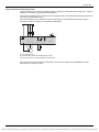
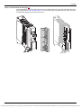
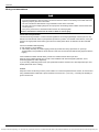
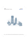
Important information
XXXXXX
Altivar 32
Variable speed drives
for synchronous and asynchronous motors
Installation manual
S1A28686
03/2010
www.schneider-electric.com
Courtesy of Steven Engineering, Inc.-230 Ryan Way, South San Francisco, CA 94080-6370-Main Office: (650) 588-9200-Outside Local Area: (800) 258-9200-www.stevenengineering.com
Important information
The information provided in this documentation contains general descriptions and/or technical characteristics
of the performance of the products contained herein. This documentation is not intended as a substitute for
and is not to be used for determining suitability or reliability of these products for specific user applications. It
is the duty of any such user or integrator to perform the appropriate and complete risk analysis, evaluation and
testing of the products with respect to the relevant specific application or use thereof. Neither Schneider
Electric nor any of its affiliates or subsidiaries shall be responsible or liable for misuse of the information
contained herein. If you have any suggestions for improvements or amendments or have found errors in this
publication, please notify us.
No part of this document may be reproduced in any form or by any means, electronic or mechanical, including
photocopying, without express written permission of Schneider Electric.
All pertinent state, regional, and local safety regulations must be observed when installing and using this
product. For reasons of safety and to help ensure compliance with documented system data, only the
manufacturer should perform repairs to components.
When devices are used for applications with technical safety requirements, the relevant instructions must be
followed.
Failure to use Schneider Electric software or approved software with our hardware products may result in
injury, harm, or improper operating results.
Failure to observe this information can result in injury or equipment damage.
© 2010 Schneider Electric. All rights reserved.
2
S1A28686 03/2010
Courtesy of Steven Engineering, Inc.-230 Ryan Way, South San Francisco, CA 94080-6370-Main Office: (650) 588-9200-Outside Local Area: (800) 258-9200-www.stevenengineering.com
Table of content
Safety Information . . . . . . . . . . . . . . . . . . . . . . . . . . . . . . . . . . . . . . . . . . . . . . . . . .4
About the book . . . . . . . . . . . . . . . . . . . . . . . . . . . . . . . . . . . . . . . . . . . . . . . . . . . . .5
Chapter 1
Introduction. . . . . . . . . . . . . . . . . . . . . . . . . . . . . . . . . . . . . . . . . . . . . . . . . . . . . . . .6
Device overview . . . . . . . . . . . . . . . . . . . . . . . . . . . . . . . . . . . . . . . . . . . . . . . . . . . . .7
Reference description. . . . . . . . . . . . . . . . . . . . . . . . . . . . . . . . . . . . . . . . . . . . . . . . .8
Chapter 2
Before you begin . . . . . . . . . . . . . . . . . . . . . . . . . . . . . . . . . . . . . . . . . . . . . . . . . . .9
Safety instructions . . . . . . . . . . . . . . . . . . . . . . . . . . . . . . . . . . . . . . . . . . . . . . . . . .10
Chapter 3
Steps for setting up . . . . . . . . . . . . . . . . . . . . . . . . . . . . . . . . . . . . . . . . . . . . . . . .12
Steps for setting up. . . . . . . . . . . . . . . . . . . . . . . . . . . . . . . . . . . . . . . . . . . . . . . . . .13
Chapter 4
Technical data. . . . . . . . . . . . . . . . . . . . . . . . . . . . . . . . . . . . . . . . . . . . . . . . . . . . .14
Mechanical data . . . . . . . . . . . . . . . . . . . . . . . . . . . . . . . . . . . . . . . . . . . . . . . . . . . .15
Electrical data . . . . . . . . . . . . . . . . . . . . . . . . . . . . . . . . . . . . . . . . . . . . . . . . . . . . . .21
Connection diagrams . . . . . . . . . . . . . . . . . . . . . . . . . . . . . . . . . . . . . . . . . . . . . . . .22
Chapter 5
Installation. . . . . . . . . . . . . . . . . . . . . . . . . . . . . . . . . . . . . . . . . . . . . . . . . . . . . . . .25
Drive mounting . . . . . . . . . . . . . . . . . . . . . . . . . . . . . . . . . . . . . . . . . . . . . . . . . . . . .26
Wiring recommendations . . . . . . . . . . . . . . . . . . . . . . . . . . . . . . . . . . . . . . . . . . . . .29
Input installation . . . . . . . . . . . . . . . . . . . . . . . . . . . . . . . . . . . . . . . . . . . . . . . . . . . .31
Output installation . . . . . . . . . . . . . . . . . . . . . . . . . . . . . . . . . . . . . . . . . . . . . . . . . . .34
Electromagnetic compatibility (EMC) . . . . . . . . . . . . . . . . . . . . . . . . . . . . . . . . . . . .38
DC bus connection . . . . . . . . . . . . . . . . . . . . . . . . . . . . . . . . . . . . . . . . . . . . . . . . . .40
Control part installation . . . . . . . . . . . . . . . . . . . . . . . . . . . . . . . . . . . . . . . . . . . . . . .42
Communication module . . . . . . . . . . . . . . . . . . . . . . . . . . . . . . . . . . . . . . . . . . . . . .46
Maintenance . . . . . . . . . . . . . . . . . . . . . . . . . . . . . . . . . . . . . . . . . . . . . . . . . . . . . . .48
Short-circuit rating and branch circuit protection . . . . . . . . . . . . . . . . . . . . . . . . . . .50
S1A28686 03/2010
3
Courtesy of Steven Engineering, Inc.-230 Ryan Way, South San Francisco, CA 94080-6370-Main Office: (650) 588-9200-Outside Local Area: (800) 258-9200-www.stevenengineering.com
Safety Information
§
Important Information
NOTICE
Read these instructions carefully, and look at the equipment to become familiar with the device before trying
to install, operate, or maintain it. The following special messages may appear throughout this documentation
or on the equipment to warn of potential hazards or to call attention to information that clarifies or simplifies a
procedure.
The addition of this symbol to a Danger or Warning safety label indicates that an electrical hazard
exists, which will result in personal injury if the instructions are not followed.
This is the safety alert symbol. It is used to alert you to potential personal injury hazards. Obey all
safety messages that follow this symbol to avoid possible injury or death.
DANGER
DANGER indicates an imminently hazardous situation, which, if not avoided, will result in death or serious
injury.
WARNING
WARNING indicates a potentially hazardous situation, which, if not avoided, can result in death, serious
injury or equipment damage.
CAUTION
CAUTION indicates a potentially hazardous situation, which, if not avoided, can result in injury or
equipment damage.
CAUTION
CAUTION, used without the safety alert symbol, indicates a potentially hazardous situation which, if not
avoided, can result in equipment damage.
PLEASE NOTE
The word "drive" as used in this manual refers to the controller portion of the adjustable speed drive as defined
by NEC.
Electrical equipment should be installed, operated, serviced, and maintained only by qualified personnel. No
responsibility is assumed by Schneider Electric for any consequences arising out of the use of this product.
© 2010 Schneider Electric. All Rights Reserved.
4
S1A28686 03/2010
Courtesy of Steven Engineering, Inc.-230 Ryan Way, South San Francisco, CA 94080-6370-Main Office: (650) 588-9200-Outside Local Area: (800) 258-9200-www.stevenengineering.com
Safety information
About the book
At a Glance
Document Scope
The purpose of this document is:
z
z
to give you mechanical and electrical information related to the ATV32 drive,
to show you how to install and wire this drive.
Validity Note
This documentation is valid for the Altivar 32 drive.
Related Documents
Title of Documentation
Reference Number
ATV32 Quick Start
S1A41715
ATV32 Programming manual
S1A28692
ATV32 Modbus manual
S1A28698
ATV32 CANopen manual
S1A28699
ATV32 Communication parameters
S1A44568
ATV32 Atex manual
S1A45605
ATV32 Safety manual
S1A45606
ATV32 other option manuals: see www.schneider-electric.com.
You can download the latest versions of these technical publications and other technical information from our
website at www.schneider-electric.com.
S1A28686 03/2010
5
Courtesy of Steven Engineering, Inc.-230 Ryan Way, South San Francisco, CA 94080-6370-Main Office: (650) 588-9200-Outside Local Area: (800) 258-9200-www.stevenengineering.com
Introduction
Introduction
1
What's in this Chapter?
This chapter contains the following topics:
Topic
6
Page
Device overview
7
Reference description
8
S1A28686 03/2010
Courtesy of Steven Engineering, Inc.-230 Ryan Way, South San Francisco, CA 94080-6370-Main Office: (650) 588-9200-Outside Local Area: (800) 258-9200-www.stevenengineering.com
Introduction
Device overview
The range
The ATV32 product family consists of four drive sizes, A, B, C and D ideally suited to implement compact, highperformance drive solutions for a wide range of power requirements.
Four sizes
Size A
ATV32H0ppM2, H0ppN4, HU1pN4
Size B
ATV32HUppM2, U22N4, U30N4, U40N4
z Single phase 240 V
z Single phase 240 V
from 0.18 kW to 0.75 kW
(1/4 HP to 1 HP)
z Three-phase 400 V
from 0.37 kW to 1.5 kW
(1/2 HP to 2 HP)
(11/2 HP to 3 HP)
z Three-phase 400 V
from 2.2 kW to 4 kW
(3 HP to 5 HP)
Size C
ATV32HU55N4, U75N4
Size D
ATV32HD11N4, D15N4
z Three-phase 400 V
z Three-phase 400 V
5.5 kW and 7.5 kW
11 kW and 15 kW
(15 HP and 20 HP)
(71/2 HP and 10 HP)
S1A28686 03/2010
from 1.1 kW to 2.2 kW
7
Courtesy of Steven Engineering, Inc.-230 Ryan Way, South San Francisco, CA 94080-6370-Main Office: (650) 588-9200-Outside Local Area: (800) 258-9200-www.stevenengineering.com
Introduction
Reference description
ATV
32
H
018
M2
Product designation
ATV - Altivar
Product range
Mounting base
H - Heatsink product
P - Baseplate product
Drive rating
018 - 0.18 kW (1/4 HP)
037 - 0.37 kW (1/2 HP)
055 - 0.55 kW (3/4 HP)
075 - 0.75 kW (1 HP)
U11 - 1.1 kW (11/2 HP)
U15 - 1.5 kW (2 HP)
U22 - 2.2 kW (3 HP)
U30 - 3 kW
U40 - 4 kW (5 HP)
U55 - 5.5 kW (71/2 HP)
U75 - 7.5 kW (10 HP)
D11 - 11 kW (15 HP)
D15 - 15 kW (20 HP)
Power supply voltage
M2 - 240 V range Single phase
N4 - 400 V range three-phase
8
S1A28686 03/2010
Courtesy of Steven Engineering, Inc.-230 Ryan Way, South San Francisco, CA 94080-6370-Main Office: (650) 588-9200-Outside Local Area: (800) 258-9200-www.stevenengineering.com
Before you begin
Before you begin
2
What's in this Chapter?
This chapter contains the following topics:
Topic
Safety instructions
S1A28686 03/2010
Page
10
9
Courtesy of Steven Engineering, Inc.-230 Ryan Way, South San Francisco, CA 94080-6370-Main Office: (650) 588-9200-Outside Local Area: (800) 258-9200-www.stevenengineering.com
Before you begin
Safety instructions
Read and understand these instructions before performing any procedure with this drive.
DANGER
HAZARD OF ELECTRIC SHOCK, EXPLOSION, OR ARC FLASH
z
Read and understand this manual before installing or operating the drive. Installation, adjustment, repair,
and maintenance must be performed by qualified personnel.
z
The user is responsible for compliance with all international and national electrical code requirements with
respect to grounding of all equipment.
z
Many parts of this drive, including the printed circuit boards, operate at the line voltage. DO NOT TOUCH.
Use only electrically insulated tools.
z
DO NOT touch unshielded components or terminal strip screw connections with voltage present.
z
DO NOT short across terminals PA/+ and PC/– or across the DC bus capacitors.
z
Before servicing the drive:
- Disconnect all power, including external control power that may be present.
- Place a “DO NOT TURN ON” label on all power disconnects.
- Lock all power disconnects in the open position.
- WAIT 15 MINUTES to allow the DC bus capacitors to discharge.
- Measure the voltage of the DC bus between the PA/+ and PC/– terminals to ensure that the voltage is less
than 42 Vdc.
- If the DC bus capacitors do not discharge completely, contact your local Schneider Electric representative.
Do not repair or operate the drive.
z
Install and close all covers before applying power or starting and stopping the drive.
Failure to follow these instructions will result in death or serious injury.
DANGER
UNINTENDED EQUIPMENT OPERATION
z
Read and understand the programming manual before operating the drive.
z
Any changes made to the parameter settings must be performed by qualified personnel.
Failure to follow these instructions will result in death or serious injury.
WARNING
DAMAGED DRIVE EQUIPMENT
Do not operate or install any drive or drive accessory that appears damaged.
Failure to follow these instructions can result in death, serious injury, or equipment damage.
WARNING
LOSS OF CONTROL
z
The designer of any wiring scheme must consider the potential failure modes of control channels and, for
certain critical control functions, provide a means to achieve a safe state during and after a channel failure.
Examples of critical control functions are emergency stop and overtravel stop.
z
Separate or redundant control channels must be provided for critical control functions.
z
System control channels may include links carried out by the communication. Consideration must be given
to the implications of unanticipated transmission delays or failures of the link1.
Failure to follow these instructions can result in death, serious injury, or equipment damage.
1. For additional information, refer to NEMA ICS 1.1 (latest edition), “Safety Guidelines for the Application, Installation, and Maintenance of Solid
State Control” and to NEMA ICS 7.1 (latest edition), “Safety Standards for Construction and Guide for Selection, Installation and Operation
of Adjustable-Speed Drive Systems.”
10
S1A28686 03/2010
Courtesy of Steven Engineering, Inc.-230 Ryan Way, South San Francisco, CA 94080-6370-Main Office: (650) 588-9200-Outside Local Area: (800) 258-9200-www.stevenengineering.com
Before you begin
CAUTION
INCOMPATIBLE LINE VOLTAGE
Before turning on and configuring the drive, ensure that the line voltage is compatible with the supply voltage
range shown on the drive nameplate. The drive may be damaged if the line voltage is not compatible.
Failure to follow these instructions can result in injury or equipment damage.
CAUTION
RISK OF DERATED PERFORMANCE DUE TO CAPACITOR AGING
The product capacitor performances after a long time storage above 2 years can be degraded.
In that case, before using the product , apply the following procedure:
z
z
Use a variable AC supply connected between L1 and L2 (even for ATV32pppN4 references).
Increase AC supply voltage to have:
- 25% of rated voltage during 30 min
- 50% of rated voltage during 30 min
- 75% of rated voltage during 30 min
- 100% of rated voltage during 30 min
Failure to follow these instructions can result in equipment damage.
S1A28686 03/2010
11
Courtesy of Steven Engineering, Inc.-230 Ryan Way, South San Francisco, CA 94080-6370-Main Office: (650) 588-9200-Outside Local Area: (800) 258-9200-www.stevenengineering.com
Steps for setting up
Steps for setting up
3
What's in this Chapter?
This chapter contains the following topics:
Topic
Steps for setting up
12
Page
13
S1A28686 03/2010
Courtesy of Steven Engineering, Inc.-230 Ryan Way, South San Francisco, CA 94080-6370-Main Office: (650) 588-9200-Outside Local Area: (800) 258-9200-www.stevenengineering.com
Steps for setting up
Steps for setting up
INSTALLATION
1. Check the delivery of the drive
v Check that the part number printed on the label is the same as that on the
purchase order.
v Remove the Altivar from its packaging and check that it has not been damaged
in transit.
2. Check the line voltage compatibilty
v Check that the voltage range of the drive is compatible with the
Steps 1 to 4 must
be performed with
the power off.
supply voltage (see page 21).
3. Mount the drive vertically
v Mount the drive in accordance with the instructions in
this document (see page 26).
v Install any options required
(see option documentation).
4. Wire the drive (see page 29)
v Connect the line supply and the ground, after
making sure that the power is off.
the motor, ensuring that
connections correspond to the voltage.
v Connect the control part.
v Connect
its
PROGRAMMING
5. Please refer to the
programming manual.
S1A28686 03/2010
13
Courtesy of Steven Engineering, Inc.-230 Ryan Way, South San Francisco, CA 94080-6370-Main Office: (650) 588-9200-Outside Local Area: (800) 258-9200-www.stevenengineering.com
Technical data
Technical data
4
What's in this Chapter?
This chapter contains the following topics:
Topic
14
Page
Mechanical data
15
Electrical data
21
Connection diagrams
22
S1A28686 03/2010
Courtesy of Steven Engineering, Inc.-230 Ryan Way, South San Francisco, CA 94080-6370-Main Office: (650) 588-9200-Outside Local Area: (800) 258-9200-www.stevenengineering.com
Technical data
Mechanical data
ATV32H0ppM2, H0ppN4, HU1pN4 - size A - dimensions and weights
224
8.82
mm
in.
152
5.98
86
3.39
45
1.77
245
9.65
232
9.13
14
0.55
7
0.28
4x Ø 5,5
4x Ø0.22
(2x Ø10)
(2x Ø0.4 )
68
2.67
255
10.04
215
8.46
258 270
10.16 10.63
325
12.80
137
5.39
96
3.78
129
5.09
317
12.48
5
0.20
Weights
S1A28686 03/2010
Reference
Weight (kg) (lb)
ATV32H018M2
1.590 (3.50)
ATV32H037M2, 055M2, 075M2
1.646 (3.63)
ATV32H037N4
1.618 (3.57)
ATV32H055N4, 075N4
1.715 (3.78)
ATV32HU11N4, U15N4
1.705 (3.76)
15
Courtesy of Steven Engineering, Inc.-230 Ryan Way, South San Francisco, CA 94080-6370-Main Office: (650) 588-9200-Outside Local Area: (800) 258-9200-www.stevenengineering.com
Technical data
ATV32HU11M2, U15M2, U22M2, U22N4, U30N4, U40N4 - Size B - dimensions and weights
224
8.82
mm
in.
152
6
101
4
60
2.36
15
0.6
9
0.35
245
9.64
234
9.21
14
0.59
42
1.65
9
0.35
4x Ø 5,5
4x Ø0.22
7
0.28
(2x Ø10)
(2x Ø0.4 )
68
2.6
255
10.04
215
8.46
258
10.16
5
0.2
129.3
5.1
270
10.63
317
12.48
137
5.39
96
3.78
325
12.80
9
0.35
Weights
16
Reference
Weight (kg) (lb)
ATV32HU11M2, U15M2
1.952 (4.30)
ATV32HU22M2
2.066 (4.55)
ATV32HU22N4
2.320 (5.11)
ATV32HU30N4
2.122 (4.68)
ATV32HU40N4
2.176 (4.80)
S1A28686 03/2010
Courtesy of Steven Engineering, Inc.-230 Ryan Way, South San Francisco, CA 94080-6370-Main Office: (650) 588-9200-Outside Local Area: (800) 258-9200-www.stevenengineering.com
Technical data
ATV32HU55N4, U75N4 - size C - dimensions and weights
mm
in.
206
8.1
150
5.9
10
5 0.4
0.2
10
0.4
130
5.12
25
1
53
2.1
190
7.48
210
8.27
10
0.4
10
0.4
130
5.12
3
0.12
232
9.23
87
3.4
181
7.12
192
7.56
220
8.66
87
3.4
232
9.13
Weight
4.20 kg (9.26 lb)
S1A28686 03/2010
17
Courtesy of Steven Engineering, Inc.-230 Ryan Way, South San Francisco, CA 94080-6370-Main Office: (650) 588-9200-Outside Local Area: (800) 258-9200-www.stevenengineering.com
Technical data
ATV32HU55N4, U75N4 - size C with EMC plate - dimensions and weight
150
5.91
308
12.13
87
3.43
115
4.53
Weight
4.41 kg (9.72 lb)
18
S1A28686 03/2010
Courtesy of Steven Engineering, Inc.-230 Ryan Way, South San Francisco, CA 94080-6370-Main Office: (650) 588-9200-Outside Local Area: (800) 258-9200-www.stevenengineering.com
Technical data
ATV32HD11N4, D15N4 - size D - dimensions and weight
mm
in.
180
7.08
7
0.27
10
0.4
10
0.4
160
6.29
80
3.15
180
7.09
142
5.59
295
11.61
160
6.3
10
0.4
10
0.4
206
8.1
181
7.12
53
2.08
245
9.65
330
13
192
7.56
310
12.2
106
4.17
232
9.13
Weight
6.750 kg (14.88 lb)
S1A28686 03/2010
19
Courtesy of Steven Engineering, Inc.-230 Ryan Way, South San Francisco, CA 94080-6370-Main Office: (650) 588-9200-Outside Local Area: (800) 258-9200-www.stevenengineering.com
Technical data
ATV32HD11N4, D15N4 - size D - with EMC plate - dimensions and weight
178
7.01
404
15.91
106
4.17
112
4.41
123
4.84
Weight
7.00 kg (15.40 lb)
20
S1A28686 03/2010
Courtesy of Steven Engineering, Inc.-230 Ryan Way, South San Francisco, CA 94080-6370-Main Office: (650) 588-9200-Outside Local Area: (800) 258-9200-www.stevenengineering.com
Technical data
Electrical data
Single phase supply voltage: 200…240 V 50/60 Hz
Motor
Line supply (input)
Power indicated
on plate (1)
Max. line current
(2)
at 200 V
Drive (output)
Apparent
power
at 240 V
Max.
inrush
current
(3)
Power
dissipated
at nominal
current
Nominal
current
(1)
Reference (5)
Size
Max.
transient
current
(1) (4)
kW
HP
A
A
kVA
A
W
A
A
0.18
1/4
3.4
2.8
0.7
9.6
25
1.5
2.3
ATV32H018M2
A
0.37
1/2
6
5
1.2
9.6
38
3.3
5.0
ATV32H037M2
A
0.55
3/4
7.9
6.7
1.6
9.6
42
3.7
5.6
ATV32H055M2
A
0.75
1
10.1
8.5
2.0
9.6
51
4.8
7.2
ATV32H075M2
A
1.1
11/2
13.6
11.5
2.8
19.1
64
6.9
10.4
ATV32HU11M2
B
1.5
2
17.6
14.8
3.6
19.1
81
8
12.0
ATV32HU15M2
B
2.2
3
23.9
20.1
4.8
19.1
102
11
16.5
ATV32HU22M2
B
Reference
Size
Three phase supply voltage: 380…500 V 50/60 Hz
Motor
Line supply (input)
Power indicated
on plate (1)
Max. line current
(2)
at
380 V
at
500 V
Drive (output)
Apparent
power
Max.
inrush
current
(3)
Power
dissipated
at nominal
current
Nominal
current
(1)
Max.
transient
current
(1) (4)
kW
HP
A
A
kVA
A
W
A
A
0.37
1/2
2.1
1.6
1.4
10
27
1.5
2.3
ATV32H037N4
A
0.55
3/4
2.8
2.2
1.9
10
31
1.9
2.9
ATV32H055N4
A
0.75
1
3.6
2.7
2.3
10
37
2.3
3.5
ATV32H075N4
A
1.1
11/2
5
3.8
3.3
10
50
3
4.5
ATV32HU11N4
A
1.5
2
6.5
4.9
4.2
10
63
4.1
6.2
ATV32HU15N4
A
2.2
3
8.7
6.6
5.7
10
78
5.5
8.3
ATV32HU22N4
B
3
–
11.1
8.4
7.3
10
100
7.1
10.7
ATV32HU30N4
B
4
5
13.7
10.5
9.1
10
125
9.5
14.3
ATV32HU40N4
B
20.7
14.5
17.9
27.6
233
14.3
21.5
ATV32HU55N4
C
25.5
ATV32HU75N4
C
1/2
5.5
7
7.5
10
26.5
18.7
22.9
27.6
263
17
11
15
36.6
25.6
31.7
36.7
403
27.7
41.6
ATV32HD11N4
D
15
20
47.3
33.3
41.0
36.7
480
33
49.5
ATV32HD15N4
D
(1) These power ratings are for a switching frequency of 4 kHz, in continuous operation. The switching frequency is adjustable
from 2 to 16 kHz.
Above 4 kHz, the drive will reduce the switching frequency if an excessive temperature rise occurs. The temperature rise
is detected by a probe in the power module. Nonetheless, derating should be applied to the nominal drive current if
continuous operation above 4 kHz is required. See page 27.
(2) Current on a line supply with the "Input withstand rating", see page 50.
(3) Peak current on power-up, for the max. voltage (240 V + 10% or 500V +10%).
(4) Note: The drive is designed to run up to 60 seconds at this level.
(5) See reference description on page 8.
S1A28686 03/2010
21
Courtesy of Steven Engineering, Inc.-230 Ryan Way, South San Francisco, CA 94080-6370-Main Office: (650) 588-9200-Outside Local Area: (800) 258-9200-www.stevenengineering.com
Technical data
Connection diagrams
Single or three-phase power supply - Diagram with line contactor
Connection diagrams conforming to standards EN 954-1 category 1 and IEC/EN 61508 capacity SIL1, stopping
category 0 in accordance with standard IEC/EN 60204-1.
- Q2
- Q3
- T1
- S2
- S1
- KM1
A1
A2
- Q2
- KM1
R1A
R1C
- KM1
(1)
P24
STO
R2C
R2A
PA/+
R1B
PC/-
PB
R1C
R1A
T / L3
W / T3
PBe
S / L2
ATV32
W1
R / L1
V / T2
V1
U1
U / T1
(2)
A1
M
3a
(1) Line choke (if used)
(2) Fault relay contacts, for remote signaling of drive status
Single or three-phase power supply - Diagram with switch disconnect
Connection diagrams conforming to standards EN 954-1 category 1 and IEC/EN 61508 capacity SIL1, stopping
category 0 in accordance with standard IEC/EN 60204-1.
(1)
P24
STO
R2C
R2A
PA/+
R1B
PC/-
R1C
PB
T / L3
W / T3
R1A
S / L2
V / T2
PBe
R / L1
U / T1
(2)
A1
ATV32
W1
V1
U1
Q1
M
3a
(1) Line choke (if used)
(2) Fault relay contacts, for remote signaling of drive status
22
S1A28686 03/2010
Courtesy of Steven Engineering, Inc.-230 Ryan Way, South San Francisco, CA 94080-6370-Main Office: (650) 588-9200-Outside Local Area: (800) 258-9200-www.stevenengineering.com
Technical data
Diagram with Preventa safety module
Connection diagrams conforming to standards EN 954-1 category 3 and IEC/EN 61508 capacity SIL2, stopping
category 0 in accordance with standard IEC/EN 60204-1.
The connection diagram below is suitable for use with machines with a short freewheel stop time (machines with
low inertia or high resistive torque).
When the emergency stop is activated, the drive power supply is cut immediately and the motor stops in
freewheel, according to category 0 of standard IEC/EN 60204-1.
A contact on the Preventa XPS AC module must be inserted in the brake control circuit to engage it safely when
the STO (Safe Torque Off) safety function is activated.
F1
L1(+)
N(-)
S2
S1
ESC
A2
A1
Y1
Y2
13
23
33
Y43
14
24
34
Y44
XPS AC
Logic
K1
T
K2
48 V, 115 V, 230 V
K1
PE
A2
K2
(1)
P24
LI2
LI1
PA/+
R1B
PC/-
PB
R1A
R1C
T / L3
W / T3
PBe
S / L2
V / T2
ATV32
W1
R / L1
U / T1
V1
U1
A1
STO
(2)
(3)
M
3a
(1) Line choke (if used)
(2) It is essential to connect the shielding to the ground.
(3) Fault relay contacts, for remote signaling of drive status
The STO safety function integrated into the product can be used to implement an "EMERGENCY STOP"
(IEC 60204-1) for category 0 stops.
With an additional, approved EMERGENCY STOP module, it is also possible to implement category 1 stops.
STO function
The STO safety function is triggered via 2 redundant inputs. The circuits of the two inputs must be separate so
that there are always two channels. The switching process must be simultaneous for both inputs (offset < 1 s).
The power stage is disabled and an error message is generated. The motor can no longer generate torque and
coasts down without braking. A restart is possible after resetting the error message with a "Fault Reset".
The power stage is disabled and an error message is generated if only one of the two inputs is switched off or if
the time offset is too great. This error message can only be reset by switching off the product.
S1A28686 03/2010
23
Courtesy of Steven Engineering, Inc.-230 Ryan Way, South San Francisco, CA 94080-6370-Main Office: (650) 588-9200-Outside Local Area: (800) 258-9200-www.stevenengineering.com
Technical data
Diagram without Preventa safety module
Connection diagrams conforming to standards EN 954-1 category 2 and IEC/EN 61508 capacity SIL1, stopping
category 0 in accordance with standard IEC/EN 60204-1.
The connection diagram below is suitable for use with machines with a short freewheel stop time (machines with
low inertia or high resistive torque).
When the emergency stop is activated, the drive power supply is cut immediately and the motor stops in
freewheel, according to category 0 of standard IEC/EN 60204-1.
(1)
P24
R2C
R2A
PA/+
R1B
PC/-
R1C
PB
R1A
T / L3
W / T3
PBe
S / L2
V / T2
ATV32
W1
R / L1
U / T1
V1
U1
A1
STO
(2)
(3)
M
3a
(1) Line choke (if used)
(2) It is essential to connect the shielding to the ground.
(3) Fault relay contacts, for remote signaling of drive status
The STO safety function integrated into the product can be used to implement an "EMERGENCY STOP"
(IEC 60204-1) for category 0 stops.
24
S1A28686 03/2010
Courtesy of Steven Engineering, Inc.-230 Ryan Way, South San Francisco, CA 94080-6370-Main Office: (650) 588-9200-Outside Local Area: (800) 258-9200-www.stevenengineering.com
Installation
Installation
5
What's in this Chapter?
This chapter contains the following topics:
Topic
S1A28686 03/2010
Page
Drive mounting
26
Input installation
31
Output installation
34
Electromagnetic compatibility (EMC)
38
DC bus connection
40
Wiring recommendations
29
Control part installation
42
Communication module
46
Maintenance
48
Short-circuit rating and branch circuit protection
50
25
Courtesy of Steven Engineering, Inc.-230 Ryan Way, South San Francisco, CA 94080-6370-Main Office: (650) 588-9200-Outside Local Area: (800) 258-9200-www.stevenengineering.com
Installation
Drive mounting
CAUTION
RISK OF DAMAGE TO THE DRIVE
Follow mounting recommandations described in this document.
Failure to follow these instructions can result in equipment damage.
≥ 50 mm
2 in.
Optional GV2
circuit-breaker
≥ 50 mm
2 in.
≥ 50 mm
2 in.
(1)
≥ 50 mm
2 in.
Mounting and temperature conditions
≥ 10 mm
0.39 in.
(1) Minimum value corresponding to thermal contrainst. On sizes A and B, a 150 mm (5.9 in.) clearance may help to connect
the ground.
z
z
z
z
z
z
Install the drive vertically, at ± 10°.
Fix it on the mounting surface using M5 screws with captive washer.
Do not place it close to heating elements.
Leave sufficient free space so that the air required for cooling purposes can circulate from the bottom to the
top of the drive.
Free space in front of the drive: 10 mm (0.39 in.) minimum.
The use of washers is recommended with all mounting screws.
Mounting types
Drive operation is suitable at surrounding air temperature less or equal to 50°C (122°F), for a switching frequency
of 4 kHz, for use in continuous operation.
Above this temperature, up to 60°C (140°F), or if operation above 4 kHz needs to be continuous, the nominal
drive current should be derated according to the derating curves.
Above 4 kHz, the drive will reduce the switching frequency automatically in the event of an excessive
temperature rise.
On optional GV2 circuit-breaker can be mounted on size A and B.
Optional GV2 circuit-breaker
26
S1A28686 03/2010
Courtesy of Steven Engineering, Inc.-230 Ryan Way, South San Francisco, CA 94080-6370-Main Office: (650) 588-9200-Outside Local Area: (800) 258-9200-www.stevenengineering.com
Installation
Derating curves
Derating curves for the nominal drive current (In) as a function of temperature and switching frequency.
ATV32HpppM2
In = 100 %
40°C (104°F)
50°C (122°F)
60°C (140°F)
90 %
80 %
70 %
60 %
50 %
Switching frequency
2 kHz
4 kHz
8 kHz
12 kHz
16 kHz
ATV32HpppN4
In = 100 %
40°C (104°F)
50°C (122°F)
90 %
60°C (140°F)
80 %
70 %
60 %
50 %
Switching frequency
2 kHz
S1A28686 03/2010
4 kHz
8 kHz
12 kHz
16 kHz
27
Courtesy of Steven Engineering, Inc.-230 Ryan Way, South San Francisco, CA 94080-6370-Main Office: (650) 588-9200-Outside Local Area: (800) 258-9200-www.stevenengineering.com
Installation
Option: Control block 90° bracket (page 26)
This optional bracket allows the drive to be mounted in a shallow enclosure. For further information about this
option, please refer to www.schneider-electric.com. This mounting type only applies to sizes A and B. The option
is supplied with detailed mounting instruction sheet.
28
S1A28686 03/2010
Courtesy of Steven Engineering, Inc.-230 Ryan Way, South San Francisco, CA 94080-6370-Main Office: (650) 588-9200-Outside Local Area: (800) 258-9200-www.stevenengineering.com
Installation
Wiring recommendations
DANGER
HAZARD OF FIRE OR ELECTRIC SHOCK
z
z
z
z
To avoid overheating or loss of contact, connections must be carried out according to the cable sizes and
tightening torques given in this document.
The use of multi-wire cable without a lug is forbidden for the mains connection.
On sizes A and B, the stripping length of the output power and braking resistor cables must be shorter than
10 mm (0.39 in.).
Carry-out a pull out test to check that terminal screws are correctly tighten.
Failure to follow these instructions will result in death or serious injury.
Power and circuit protection
The drive must be grounded to conform with the regulations concerning high leakage currents (over 3.5 mA).
Where local and national codes require upstream protection by means of a residual current device, use a type
A device for single-phase drives and a type B device for three-phase drives as defined in the IEC Standard
60755.
Choose a suitable model integrating:
z
z
High frequency current filtering,
A time delay that helps to prevent tripping caused by the load from stray capacitance on power-up.
The time delay is not possible for 30 mA devices; in this case, choose devices with immunity against nuisance
tripping.
If the installation includes several drives, provide one "residual current device" per drive.
Keep the power cables separate from circuits in the installation with low-level signals (detectors, PLCs,
measuring apparatus, video, telephone).
If you are using cables longer than 50 m (164 ft) between the drive and the motor, add output filters (for more
details please refer to the catalog).
Control
Keep the control circuits away from the power cables. For control and speed reference circuits, we recommend
using shielded twisted cables with a pitch of between 25 and 50 mm (1 and 2 in.), connecting the shielding to
ground at each end.
S1A28686 03/2010
29
Courtesy of Steven Engineering, Inc.-230 Ryan Way, South San Francisco, CA 94080-6370-Main Office: (650) 588-9200-Outside Local Area: (800) 258-9200-www.stevenengineering.com
Installation
Equipment Grounding
Ground the drive according to local and national code requirements. A minimum wire size of 10 mm² (6 AWG)
may be required to meet standards limiting leakage current.
DANGER
HAZARD OF ELECTRIC SHOCK, EXPLOSION, OR ARC FLASH
z
z
The drive panel must be properly grounded before power is applied.
Use the provided ground connecting point as shown in the figure.
Failure to follow these instructions will result in death or serious injury.
WARNING
INADEQUATE OVERCURRENT PROTECTION
z
z
z
Overcurrent protective devices must be properly coordinated.
The Canadian Electrical Code and the National Electrical Code require branch circuit protection. Use the
fuses recommended in this manual.
Do not connect the drive to a power feeder whose short-circuit capacity exceeds the maximum prospective
line Isc listed in this manual.
Failure to follow these instructions can result in death, serious injury, or equipment damage.
CAUTION
RISK OF DAMAGE TO THE DRIVE
z
z
z
The drive will be damaged if input line voltage is applied to the output terminals (U/T1,V/T2,W/T3).
Check the power connections before energizing the drive.
If replacing the existing drive by another drive, verify that all wiring connections to the drive comply with
wiring instructions in this manual
Failure to follow these instructions can result in equipment damage.
30
z
Ensure that the resistance of the ground is one ohm or less.
z
When grounding several drives, you must connect each one directly, as
shown in the figure to the left.
z
Do not loop the ground cables or connect them in series.
S1A28686 03/2010
Courtesy of Steven Engineering, Inc.-230 Ryan Way, South San Francisco, CA 94080-6370-Main Office: (650) 588-9200-Outside Local Area: (800) 258-9200-www.stevenengineering.com
Installation
Input installation
Access to the power supply terminals - Sizes A and B
DANGER
HAZARD OF ELECTRIC SHOCK, EXPLOSION, OR ARC FLASH.
z
Replace all the wiring traps before applying power.
Failure to follow these instructions will result in death or serious injury.
Power supply terminals are located on the top of the drive.
Motor and braking resistor terminals are located on the bottom of the drive. Arrangement and characteristics of
the power terminals are given on page 36.
To access input terminals, manually pull and tip up the wiring trap. Insert the wires into the terminals and
connect the ground wire to the ground screw. Tighten the terminal screws. Replace the wiring trap. Output
and brake terminals are accessible directly on the plug-in connector. See detailed connector mounting and cable
arrangement on page 34.
t
2
R/L1
S/L2
T/L3
1
3
4
S1A28686 03/2010
31
Courtesy of Steven Engineering, Inc.-230 Ryan Way, South San Francisco, CA 94080-6370-Main Office: (650) 588-9200-Outside Local Area: (800) 258-9200-www.stevenengineering.com
Installation
Option: protection device, GV2 circuit-breaker
The ATV32 size A and B are prepared to be equipped with an optional GV2 circuit-breaker. For further
information about the optional GV2 circuit-breaker, bracket and adaptor plate, please refer to www.schneiderelectric.com. The options are supplied with detailed mounting instruction sheet.
Note: The product overall dimension, including GV2 adapter and EMC plate mounted, becomes 424 mm
(16.7 in.)
GV2
circuit-breaker
Bracket
for GV2/ATV 32
direct mounting
Adaptor plate
32
S1A28686 03/2010
Courtesy of Steven Engineering, Inc.-230 Ryan Way, South San Francisco, CA 94080-6370-Main Office: (650) 588-9200-Outside Local Area: (800) 258-9200-www.stevenengineering.com
Installation
Access to the power terminals - Sizes C and D
Power supply terminals, Motor terminals and Braking resistor terminals are located on the bottom of the drive.
To access the terminals, remove the wiring trap by pushing the locking tab using a screwdriver as shown
below. Then remove the terminal cover .
Access to the braking resistor terminals - All sizes
Access to the braking resistor terminals is protected by breakable plastic parts. Use a screwdriver to remove
these protective parts.
S1A28686 03/2010
33
Courtesy of Steven Engineering, Inc.-230 Ryan Way, South San Francisco, CA 94080-6370-Main Office: (650) 588-9200-Outside Local Area: (800) 258-9200-www.stevenengineering.com
Installation
Output installation
Plug-in output connector and EMC plate assembly fitting
On size A and B drives
The EMC plate and the plug-in output power and braking unit terminal are fitted inseparably together.
Input terminals are located on the top of the drive, see page 31. Arrangement and characteristics of the power
terminals are given on page 36.
Plug the output power terminal. Insert the fixing and the grounding screws (print: plus minus HS type 2).
Tighten to 1 to 1.5 N.m (8.9 to 13.3 lb.in). Cabling can be carried out with the connector mounted on the drive
or not.
Cabling will be easier if carried out in this order: brake (1), motor and ground (2). Lastly mount the bridge
intended to receive the control wires (3). See detailed cable arrangment in page 37.
Nm
lb/in
1 ... 1.5
8.9 ... 13.3
On size C drives
The EMC plate supplied in the package is fitted at the bottom of the drive, using 3 x M5 HS type 2 screws.
fixing screws
On size D drives
The EMC plate supplied in the package is fitted at the bottom of the drive, using 2 x M5 HS type 2 screws.
fixing screws
t
t
34
t
S1A28686 03/2010
Courtesy of Steven Engineering, Inc.-230 Ryan Way, South San Francisco, CA 94080-6370-Main Office: (650) 588-9200-Outside Local Area: (800) 258-9200-www.stevenengineering.com
Installation
Functions of the power terminals
Terminal
Function
For Altivar 32
t
Ground terminal
All ratings
R/L1 - S/L2/N
Power supply
ATV32ppppM2
R/L1 - S/L2 - T/L3
ATV32ppppN4
PB
Output to braking resistor (1)
All ratings
PBe
Output to braking resistor (+ polarity) (1)
All ratings
PA/+
DC bus + polarity
Size C and D
PC/-
DC bus - polarity
Size C and D
U/T1 - V/T2 - W/T3
Outputs to the motor
All ratings
(1) For further information about the braking resistor option, please refer to www.schneider-electric.com.
S1A28686 03/2010
35
Courtesy of Steven Engineering, Inc.-230 Ryan Way, South San Francisco, CA 94080-6370-Main Office: (650) 588-9200-Outside Local Area: (800) 258-9200-www.stevenengineering.com
Installation
Arrangement and characteristics of the power terminals
t
R/L1
S/L2
size A
Wires size
T/L3
PBe PB
ATV32H0ppM2,
0ppN4, U1pN4
bottom terminals
Size B
t
S/L2
top terminals
PBe
N·m
(lb.in)
0.6
(5.3)
t
t
Input power
Output power and
braking resistor
PB PBe PA/+ PC/- U/T1 V/T2 W/T3
t
Tightening
torque
Wires size
Tightening
torque
Rated
Min.
Max.
Min. to Max.
N·m
(lb.in)
mm²
(AWG)
mm²
(AWG)
N·m
(lb.in)
ATV32HU22N4,
U30N4
1.5
(14)
4
(10)
0.6
(5.3)
1.5
(14)
2.5
(12)
0.7 to 0.8
(6.2 to 7.1)
U11M2, U40N4
2.5
(12)
4
(10)
0.6
(5.3)
1.5
(14)
2.5
(12)
0.7 to 0.8
(6.2 to 7.1)
U15M2
2.5
(10)
4
(10)
0.6
(5.3)
1.5
(14)
2.5
(12)
0.7 to 0.8
(6.2 to 7.1)
U22M2
4
(10)
4
(10)
0.6
(5.3)
1.5
(14)
2.5
(12)
0.7 to 0.8
(6.2 to 7.1)
U75N4
size D
R/L1 S/L2 T/L3
mm²
(AWG)
2.5
(12)
mm²
(AWG)
ATV32HU55N4
PBe PA/+ PC/- U/T1 V/T2 W/T3
mm²
(AWG)
1.5
(14)
Max.
R/L1 S/L2 T/L3
36
mm²
(AWG)
4
(10)
Max.
Min.
size C
t
mm²
(AWG)
1.5
(14)
Min.
Tightening
torque
Min. to
Max.
N·m
(lb.in)
0.7 to 0.8
(6.2 to 7.1)
mm²
(AWG)
PB U/T1 V/T2 W/T3
bottom terminals
t
Max.
Wires size
T/L3
PB
Min.
Tightening
torque
Rated
Output power and
braking resistor
Wires size
U/T1 V/T2 W/T3
top terminals
R/L1
Input power
Input power
Output power and
braking resistor
Wires size
Tightening
Wires size
Tightening
torque
torque
Min.
Max.
Min. to Max.
Min.
Max.
Min. to Max.
mm²
mm²
N·m
mm²
mm²
N·m
(AWG) (AWG)
(lb.in)
(AWG) (AWG)
(lb.in)
4
16
1.2 to 1.5
2.5
16
1.2 to 1.5
(10)
(6)
(10.6 to 13.3) (12)
(6)
(10.6 to 13.3)
6
16
1.2 to 1.5
2.5
16
1.2 to 1.5
(8)
(6)
(10.6 to 13.3) (10)
(6)
(10.6 to 13.3)
Input power
Output power and
braking resistor
Wires size
Tightening
Wires size
Tightening
torque
torque
Min.
Max.
Min. to Max.
Min.
Max.
Min. to Max.
mm²
mm²
N·m
mm²
mm²
N·m
(AWG) (AWG)
(lb.in)
(AWG) (AWG)
(lb.in)
ATV32HD11N4
10
16
1.2 to 1.5
6
16
1.2 to 1.5
(8)
(6)
(10.6 to 13.3)
(8)
(6)
(10.6 to 13.3)
D15N4
16
16
1.2 to 1.5
6
16
1.2 to 1.5
(6)
(6)
(10.6 to 13.3)
(8)
(6)
(10.6 to 13.3)
S1A28686 03/2010
Courtesy of Steven Engineering, Inc.-230 Ryan Way, South San Francisco, CA 94080-6370-Main Office: (650) 588-9200-Outside Local Area: (800) 258-9200-www.stevenengineering.com
Installation
EMC plates cable arrangement
Sizes A and B
Size C
10
Size D
10
Altivar 32.
Sheet steel grounded EMC plate.
Shielded cable for braking resistor connection (if used). The shielding must be continuous and intermediate
terminals must be in EMC plate.
Control EMC plate.
Shielded cable for control-signal section and STO safety function input connection.
Holes for installing the control EMC plate.
Shielded cable for motor connection, with shielding connected to ground at both ends. The shielding must be
continuous and intermediate terminals must be in EMC plate.
Non-shielded wires for relay contact output.
Protective ground connection.
10
S1A28686 03/2010
Non-shielded cable or wires for drive power supply.
37
Courtesy of Steven Engineering, Inc.-230 Ryan Way, South San Francisco, CA 94080-6370-Main Office: (650) 588-9200-Outside Local Area: (800) 258-9200-www.stevenengineering.com
Installation
Electromagnetic compatibility (EMC)
NOTE: The high frequency equipotential ground connection between the drive, motor, and cable shielding does
not eliminate the need to connect the ground (PE) conductors (green-yellow) to the appropriate terminals on
each unit.
Principle and precautions
z
Grounds between the drive, motor, and cable shielding must have high frequency equipotentiality.
z
When using shielded cable for the motor, use a 4-conductor cable so that one wire will be the ground
connection between the motor and the drive. Size of the ground conductor must be selected in compliance
with local and national codes. The shield can then be grounded at both cable ends. Metal ducting or conduit
can be used for part or all of the shielding length, provided there is no break in continuity.
z
When using shielded cable for Dynamic Brake (DB) resistors, use a 3-conductor cable so that one wire will
be the ground connection between the DB resistor assembly and the drive. The size of the ground conductor
must be selected in compliance with local and national codes. The shield can then be grounded at both cable
ends. Metal ducting or conduit can be used for part or all of the shielding length, provided there is no break in
continuity.
z
When using shielded cable for control signals, if the cable is connecting equipment that is close together and
the grounds are bonded together, then both ends of the shield can be grounded. If the cable is connected to
equipment that may have a different ground potential, then ground the shield at one end only to help prevent
large currents from flowing in the shield. The shield on the ungrounded end may be tied to ground with a
capacitor (for example: 10 nF, 100 V or higher) in order to provide a path for the higher frequency noise. Keep
the control circuits away from the power circuits. For control and speed reference circuits, we recommend
using shielded twisted cables with a pitch of between 25 and 50 mm (1 and 2 in.) Keep the control circuits
away from the power circuits.
z
Ensure maximum separation between the power supply cable (line supply) and the motor cable.
z
The motor cables must be at least 0.5 m (20 in.) long.
z
Do not use surge arresters or power factor correction capacitors on the variable speed drive output.
z
If using an additional input filter, it should be mounted as closed as possible to the drive and connected directly
to the line supply via an unshielded cable. Link on the drive is via the filter output cable.
z
For installation of the EMC plate and instructions for meeting IEC 61800-3 standard, refer to the section
entitled “Installing the EMC plates”.
DANGER
HAZARD OF ELECTRIC SHOCK, EXPLOSION, OR ARC FLASH
z
z
Do not expose cable shielding except where connected to ground at the metal cable glands and underneath
the grounding clamps.
Ensure that there is no risk of the shielding coming into contact with live components.
Failure to follow these instructions will result in death or serious injury.
Mains impedance
CAUTION
RISK OF LIFE DURATION AND EMC PERFORMANCES DECREASE
z
z
z
Do not connect the drive to a low impedance network.
The input withstand current must not exceed the value in the table page 50.
Installation and supply greater than this value will require an additionnal inductance.
Failure to follow these instructions can result in equipment damage.
38
S1A28686 03/2010
Courtesy of Steven Engineering, Inc.-230 Ryan Way, South San Francisco, CA 94080-6370-Main Office: (650) 588-9200-Outside Local Area: (800) 258-9200-www.stevenengineering.com
Installation
Operation on an IT system
IT system: Isolated or impedance grounded neutral. Use a permanent insulation monitor compatible with nonlinear loads, such as a XM200 type or equivalent.
DANGER
HAZARD OF ELECTRIC SHOCK, EXPLOSION, OR ARC FLASH
Read and understand the precautions in "before you begin" chapter, before performing the procedure in this
section.
Failure to follow these instructions will result in death or serious injury.
ATV32 drives have a built-in EMC filter. As a result they exhibit leakage current to ground. If the leakage current
creates compatibility problems with your installation (residual current device or other), then you can reduce the
leakage current by opening the IT jumper as shown below. In this configuration EMC compliance is not
guaranteed.
On sizes A and B the IT jumper is located on top of the product, behind the GV2 circuit-breaker adaptor mounting
screws.
On sizes C and D it is located on front side, behind the power terminals protective cover, on the left hand side
of the power input terminals.
Normal (filter connected)
IT system (filter disconnected)
IT system (filter disconnected)
Normal (filter connected)
C and D sizes
A and B sizes
S1A28686 03/2010
39
Courtesy of Steven Engineering, Inc.-230 Ryan Way, South San Francisco, CA 94080-6370-Main Office: (650) 588-9200-Outside Local Area: (800) 258-9200-www.stevenengineering.com
Installation
DC bus connection
Uses overview
Drive fed by the AC mains with common DC link
This use is suitable in case of equivalent drive ratings (or not more than 1 rating difference). Each product is fed
by the standard main inputs and all products are linked by their DC Bus connection.
The goal of this DC Bus sharing function is to save energy. When a drive is braking, the energy can be reused
by another drive on the DC Bus network instead of being dissipated (and so wasted) in a braking resistor.
Moreover, this kind of cabling enables to reduce the braking resistor value and help improving braking
performance without braking resistor.
Drive only fed by the DC link
This use is suitable when combining different drive ratings (more than one rating different).
One product is fed by the main network and feeds other products via the DC Bus cable connection.
This kind of installation has the same energy benefit than the previous one but requires at least one higher rating
product, able to supply the other ones.
Drive fed by a DC power supply
All products are fed by an external DC power supply via the DC Bus cable connection.
This kind of installation requires to achieve the following requirements:
z
z
z
This source must be protected against phase to phase short-circuit and earth short-circuit.
The source must be able to give the sum of all DC drive current used in same time.
This DC source must integrate DC choke to limit the ripple current less than 5%.
Drive preparation
DANGER
HAZARD OF ELECTRIC SHOCK OR ARC FLASH
z
z
z
z
Only use dedicated cable references from the catalog.
As cable is the same for both voltage ranges, ensure voltage range before cabling.
Use a screwdriver to remove the DC connector protective covers, instead of precision knife or scissors.
If the DC bus cable is removed, replace the DC bus protective plastic caps provided with the drive.
Failure to follow these instructions will result in death or serious injury.
DC bus connectors are located on top of the drive on size A and B. Break the protective covers, using a
screwdriver. These covers can easily be removed using a screwdriver
. Remove the plastic protective caps
from the terminals . When not connected, the DC bus terminals should be covered using the plastic caps. Once
this is done the drive becomes IP20 again. If lost, the plastic caps are also available as spare parts.
40
S1A28686 03/2010
Courtesy of Steven Engineering, Inc.-230 Ryan Way, South San Francisco, CA 94080-6370-Main Office: (650) 588-9200-Outside Local Area: (800) 258-9200-www.stevenengineering.com
Installation
Connection examples
Technical information
For further technical information on DC bus connection, please refer to www.schneider-electric.com.
S1A28686 03/2010
41
Courtesy of Steven Engineering, Inc.-230 Ryan Way, South San Francisco, CA 94080-6370-Main Office: (650) 588-9200-Outside Local Area: (800) 258-9200-www.stevenengineering.com
Installation
Control part installation
Access to the control terminals
Access to the terminals is the same on all products. Just open the cover as shown in the example below.
All screws are M3 slotted type, 3.8 mm (0.15 in.) diameter.
Source
Sink ext.
Sink int.
SW1
R2A
R2C
STO
LI6
SW2
P24
PTC
LO+
LO-
RJ45 socket
LI6
LI5
LI4
LI3
LI2
LI1
R1A
R1B
R1C
COM
AO1
COM
AI3
AI2
10V
AI1
COM
+24
DANGER
HAZARD OF ELECTRIC SHOCK, EXPLOSION, OR ARC FLASH
Read and understand the precautions in "before you begin" chapter, before performing the procedure in this
section.
Failure to follow these instructions will result in death or serious injury.
Control connection diagram in source mode
x-y mA
-10V..10Vdc
c
(1)
a
+24
COM
AI1
10V
AI2
AI3
COM
A01
COM
R1C
R1A
A1
R1B
b
LI1
LI2
LI3
LI4
LI5
LI6
L0-
L0+
P24
STO
R2C
R2A
ATV32
(1) Reference potentiometer SZ1RV1202 (2.2 kΩ) or similar (10 kΩ maximum)
42
S1A28686 03/2010
Courtesy of Steven Engineering, Inc.-230 Ryan Way, South San Francisco, CA 94080-6370-Main Office: (650) 588-9200-Outside Local Area: (800) 258-9200-www.stevenengineering.com
Installation
Arrangement of the control terminals
ATV32H
control
terminals
Minimum (1)
Wire size
Maximum
Tightening
torque
mm² (AWG)
mm² (AWG)
N·m (lb.in)
R1A, R1B, R1C,
R2A, R2C
0.75 (18)
1.5 (16)
0.5 (4.4)
All other terminals
0.5 (20)
1.5 (16)
0.5 (4.4)
(1) The value in bold corresponds to the minimum wire gauge to permit secureness.
Characteristics and functions of the control terminals
S1A28686 03/2010
Terminal
Function
Type
Electrical characteristics
R1A
NO contact of the relay
I/O
R1B
NC contact of the relay
I/O
R1C
Common point contact of
programmable relay R1
I/O
• Min. switching capacity: 5 mA for 24 V c
• Max. switching capacity on resistive load: (cos ϕ = 1)
3 A for 250 V a and 4 A for 30 V c
• Max. switching capacity on inductive load: (cos ϕ = 0.4 and L/R =
7 ms):
2 A for 250 V a and 30 V c
• Refresh time: 2 ms
• Service life: 100,000 operations at max. switching power
COM
Analog I/O common
I/O
0V
AO1
Voltage or current analog
output (collector)
O
Analog output 0 to 10 V, min. load impedance 470 Ω
or
Analog output 0 to 20 mA, max. load impedance 800 Ω
• Resolution 10 bits
• Precision ± 1% in 50/60Hz for 25°C ±10°C, ± 2% in 50/60Hz for 10 to +60°C
• Linearity ± 0.3%
• Sampling time 2 ms
COM
Analog I/O common
I/O
0V
AI3
Analog input current
I
Analog input 0-20 mA (or 4-20 mA, X-20 mA, 20-Y mA). X and Y can
be programmed from 0 to 20 mA
• Impedance 250 Ω
• Resolution: 10 bits
• Precision ±0.5% in 50/60 Hz for 25 °C, ±0.2% in 50/60 Hz for –10
to +60 °C at Δθ = 60°C,
• Linearity ± 0.2% (max. ± 0.5%), of max. value
• Sampling time 2 ms
AI2
Analog input voltage
I
Bipolar analog input 0 ± 10 V (maximum voltage ± 30 V)
The + or - polarity of the voltage on AI2 affects the direction of
the setpoint and therefore the direction of operation.
• Impedance 30 kΩ
• Resolution: 10 bits
• Precision ±0.5% in 50/60 Hz for 25 °C, ±0.2% in 50/60 Hz for –10
to +60 °C at Δθ = 60°C,
• Linearity ± 0.2% (max. ± 0.5%), of max. value
• Sampling time 2 ms
10 V
Power supply for
reference potentiometer
O
+10 Vdc
• Tolerance: 0..+10%
• Current: 10 mA max
AI1
Analog input voltage
I
Analog input: 0 + 10 V
• Impedance: 30 kΩ
• Resolution: 10 bits converter
• Precision: ±0.5% in 50/60 Hz for 25 °C, ±0.2% in 50/60 Hz for –10
to +60 °C at Δθ = 60°C,
• Linearity ± 0.2% (max. ± 0.5%), of max. value
• Sampling time: 2 ms
COM
Analog I/O common
I/O
0V
43
Courtesy of Steven Engineering, Inc.-230 Ryan Way, South San Francisco, CA 94080-6370-Main Office: (650) 588-9200-Outside Local Area: (800) 258-9200-www.stevenengineering.com
Installation
Terminal
Function
Type
Electrical characteristics
+24
Logic input power supply
O
+24 Vdc
• Tolerance: -15..+20%
• Current: 100 mA
R2A
R2C
NO contact of
programmable
relay R2
I/O
• Min. switching capacity: 5 mA for 24 V c
• Max. switching capacity on resistive load: (cos ϕ = 1)
5 A for 250 V a and 30 V c
• Max. switching capacity on inductive load:
(cos ϕ = 0.4 and L/R = 7 ms):
2 A for 250 V a and 30 V c
• Refresh time: 2 ms
• Service life:
- 100,000 operations at max. switching power
- 1,000,000 operations with 500mA current to inductive
load 58 Vac or 30 Vdc
STO
STO (Safe Torque Off)
safety function input
I
24 Vdc
• Impedance 1.5 kΩ
P24
External power supply for
control circuit / Internal
power supply for STO
I/O
+24 Vdc
• Tolerance: -15..+20%
• Current: 1.1 A max.
LO+
LO-
Logic output
O
Open collector output configurable as sink or source using SW1
switch
• Refresh time: 2 ms
• Maximum current: 100 mA
• Maximum voltage: 30 V
LI6
LI5
Logic inputs
I
If programmed as logic inputs, same characteristics as LI1 to LI4.
• LI5 can be programmed as pulse input 20 kpps (pulse per second).
• LI6 can be used as PTC using SW2 switch.
• Trip threshold 3 kΩ, reset threshold 1.8 kΩ
• Short-circuit detection threshold < 50 Ω
LI4
LI3
LI2
LI1
Logic inputs
I
4 programmable logic inputs configurable as sink or source using
SW1 switch
• + 24 V power supply (max. 30 V)
• State 0 if < 5 V, state 1 if > 11 V (in source mode)
• State 0 if > 19 V, state 1 if < 13 V (in sink mode)
• Response time 8 ms at Stop
RJ45 Communication port
It is used to connect:
z
z
z
z
a PC using SoMove software,
a graphic or remote keypad,
Modbus or CANopen network,
Configuration loader tools...
Note: Check that RJ45 cable is not damaged prior to connect it to the product otherwise the power supply of the
control could be lost.
44
S1A28686 03/2010
Courtesy of Steven Engineering, Inc.-230 Ryan Way, South San Francisco, CA 94080-6370-Main Office: (650) 588-9200-Outside Local Area: (800) 258-9200-www.stevenengineering.com
Installation
Sink / source switch configuration (SW1)
DANGER
UNINTENDED EQUIPMENT OPERATION
z
z
z
z
When switch SW1 is set to "Sink Int" or "Sink Ext", the COM terminal must never be connected to ground
or to protective ground. There is a risk of unintended equipment operation on the first insulation fault.
Prevent accidental grounding of logic inputs configured for sink logic. Accidental grounding can result in
unintended activation of drive functions.
Protect the signal conductors against damage that could result in unintentional conductor grounding.
Follow NFPA 79 and EN 60204 guidelines for proper control circuit grounding practices
Failure to follow these instructions will result in death or serious injury.
CAUTION
RISK OF BODY INJURY
Use a screwdriver to change the position of the switch.
Failure to follow these instructions can result in injury or equipment damage.
The logic input switch (SW1) is used to adapt the operation of the logic inputs to the technology of the
programmable controller outputs. To access to SW1, open the control terminals door. The SW1 is located on the
left side of the control terminals, see page 42.
Set the switch to Source (factory setting) if using PLC outputs with PNP transistors.
Set the switch to Sink Int or Sink Ext if using PLC outputs with NPN transistors.
0V
LI1
Int
LI2
ATV32
Ext
LI3
Sink
0V
LI1
SW1
LI2
LI4
LI5
Int
LI6
Ext
A1
LI4
ATV32
+24
Sink
Source
A1
LI3
Source
SW1
Switch SW1 set to "Source" position and use of an external
power supply for the LIs
LI5
Switch SW1 set to "Source" position
LI6
z
+24
z
24 V c source
+24 V
0V
0V
LI1
LI2
LI3
LI4
ATV32
Int
LI5
Sink
A1
Ext
+24
0V
LI1
SW1
LI2
LI3
Int
LI5
Ext
LI6
Sink
ATV32
+24
SW1
Source
A1
LI4
Source
Switch SW1 set to "Sink Ext" position
LI6
Switch SW1 set to "Sink Int" position
24 V c source
+24 V
0V
S1A28686 03/2010
45
Courtesy of Steven Engineering, Inc.-230 Ryan Way, South San Francisco, CA 94080-6370-Main Office: (650) 588-9200-Outside Local Area: (800) 258-9200-www.stevenengineering.com
Installation
Communication module
CAUTION
RISK OF DAMAGE TO THE DRIVE
z
Install only communication modules designed for the drive. See references in the catalog.
z
Do not insert any other thing than communication module inside the drive.
Failure to follow these instructions can result in equipment damage.
The ATV32 drive is designed to be fitted with optional communication modules. These modules slide directly into
the control block as shown below. For further information related to the communication modules, please refer to
the option module communication guides.
Install the communication module in ATV32 as follows:
46
Step
Action
Comment
1
Find out the position of the module on the ATV32
2
Extract the cover
3
Insert the option module
4
Check that the module is inserted and locked mechanically in the drive.
S1A28686 03/2010
Courtesy of Steven Engineering, Inc.-230 Ryan Way, South San Francisco, CA 94080-6370-Main Office: (650) 588-9200-Outside Local Area: (800) 258-9200-www.stevenengineering.com
Installation
Extract the communication module as follows:
S1A28686 03/2010
Step
Action
1
Ensure that the power is off.
Press the strip.
2
Extract the module while maintening
the strip pressed.
Comment
47
Courtesy of Steven Engineering, Inc.-230 Ryan Way, South San Francisco, CA 94080-6370-Main Office: (650) 588-9200-Outside Local Area: (800) 258-9200-www.stevenengineering.com
Installation
Maintenance
DANGER
HAZARD OF ELECTRIC SHOCK, EXPLOSION, OR ARC FLASH
Read and understand the precautions in "before you begin" chapter, before performing the procedure in this
section.
Failure to follow these instructions will result in death or serious injury.
Limitation of Warranty
The warranty does not apply if the product has been opened, except by Schneider Electric services.
Servicing
CAUTION
RISK OF DAMAGE TO THE DRIVE
Adapt the following recommendations according to the environment conditions: temperature, chemical, dust,
vibration.
Failure to follow these instructions can result in equipment damage.
It is recommended to do the following in order to optimize continuity of operation.
Environment
Part concerned
Action
Knock on the product
Housing - control block
(led - display)
Check the drive visual aspect At least each year
Corrosion
Terminals - connector - screws EMC plate
Inspect and clean if required
Dust
Terminals - fans - blowholes
Temperature
Around the product
Check and correct if required
Cooling
Fan
Check the fan operation
At least each year
Replace the fan (page 49)
after 3 to 5 years, depending
on the operating conditions
Check tightening at recommended torque
At least each year
Vibration
Terminal connections
Periodicity
Note: The fan operation depends of the drive thermal state. The drive may be running and the fan not.
Spares and repairs
Serviceable product. Please refer to your Customer Care Centre.
Long time storage
The product capacitor performances after a long time storage above 2 years can be degraded. See page 11.
48
S1A28686 03/2010
Courtesy of Steven Engineering, Inc.-230 Ryan Way, South San Francisco, CA 94080-6370-Main Office: (650) 588-9200-Outside Local Area: (800) 258-9200-www.stevenengineering.com
Installation
Fan replacement
It is possible to order a new fan for the ATV32 maintenance, see the commercial references on www.schneiderelectric.com.
Push the locking tab.
On sizes A and B
Disconnect the plug-in connector and remove the fan.
On size C
On size D
S1A28686 03/2010
49
Courtesy of Steven Engineering, Inc.-230 Ryan Way, South San Francisco, CA 94080-6370-Main Office: (650) 588-9200-Outside Local Area: (800) 258-9200-www.stevenengineering.com
Installation
Short-circuit rating and branch circuit protection
Recommended fuse ratings for UL and CSA requirements
Reference
Voltage
(Y)
ATV32H018M2
V
200-240
Input
withstand
rating (1)
kA
1
Output
interrupt
rating (X)(2)
kA
5
ATV32H037M2
200-240
1
5
ATV32H055M2
200-240
1
5
ATV32H075M2
200-240
1
5
ATV32HU11M2
200-240
1
5
ATV32HU15M2
200-240
1
5
ATV32HU22M2
200-240
1
5
ATV32H037N4
380-500
5
5
ATV32H055N4
380-500
5
5
ATV32H075N4
380-500
5
5
ATV32HU11N4
380-500
5
5
ATV32HU15N4
380-500
5
5
ATV32HU22N4
380-500
5
5
ATV32HU30N4
380-500
5
5
ATV32HU40N4
380-500
5
5
ATV32HU55N4
380-500
22
22
ATV32HU75N4
380-500
22
22
ATV32HD11N4
380-500
22
22
ATV32HD15N4
380-500
22
22
Branch
Circuit
protection
(Z1)
Fast Acting Class CC
Ferraz ATDR
Fast Acting Class J
Ferraz HSJ
Fast Acting Class J
Ferraz HSJ
Fast Acting Class J
Ferraz HSJ
Fast Acting Class J
Ferraz HSJ
Fast Acting Class J
Ferraz HSJ
Fast Acting Class J
Ferraz HSJ
Fast Acting Class CC
Ferraz ATDR
Fast Acting Class CC
Ferraz ATDR
Fast Acting Class CC
Ferraz ATDR
Fast Acting Class CC
Ferraz ATDR
Fast Acting Class CC
Ferraz ATDR
Fast Acting Class J
Ferraz HSJ
Fast Acting Class J
Ferraz HSJ
Fast Acting Class J
Ferraz HSJ
Fast Acting Class J
Ferraz HSJ
Fast Acting Class J
Ferraz HSJ
Fast Acting Class J
Ferraz HSJ
Fast Acting Class J
Ferraz HSJ
Rating
(Z2)
A
7
15
25
25
25
40
45
6
6
6
12
12
15
17.5
25
40
40
60
70
Components for use together in accordance with standard UL508
Suitable For Use On A Circuit Capable Of Delivering Not More Than ___X____ rms Symmetrical Amperes,
___Y____ Volts Maximum, When Protected by __Z 1____ with a Maximum rating of__Z 2___.
(1) Input withstand rating is that for which the product has been designed thermally. Installation on a supply
greater than this level will require additional inductance to satisfy this level.
(2) Output interrupt rating relies on Integral solid state short circuit protection. This does not provide branch
circuit protection. Branch circuit protection must be provided in accordance with the National Electrical Code and
any additional local codes. This is dependant on the type of installation.
50
S1A28686 03/2010
Courtesy of Steven Engineering, Inc.-230 Ryan Way, South San Francisco, CA 94080-6370-Main Office: (650) 588-9200-Outside Local Area: (800) 258-9200-www.stevenengineering.com
ATV32_installation_manual_S1A28686_01
03/2010
Courtesy of Steven Engineering, Inc.-230 Ryan Way, South San Francisco, CA 94080-6370-Main Office: (650) 588-9200-Outside Local Area: (800) 258-9200-www.stevenengineering.com