1
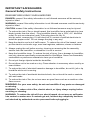
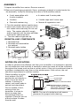
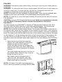
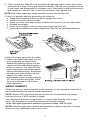
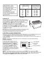
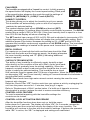
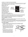
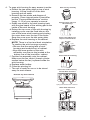
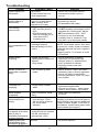
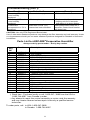
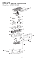
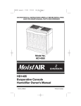
READ AND SAVE THESE INSTRUCTIONS ® DUAL FAN CONSOLE EVAPORATIVE HUMIDIFIER (14 GALLON SERIES) USE AND CARE GUIDE Adjustable Humidistat Easy fill bottles Four Casters EA1407 ; HD1409 Français ………….17 Español ………..…33 TO ORDER PARTS AND ACCESSORIES CALL 1.800.547.3888 1B72673 5/2014 PRINTED IN CHINA IMPORTANT SAFEGUARDS General Safety Instructions READ BEFORE USING YOUR HUMIDIFIER DANGER: means if the safety information is not followed someone will be seriously injured or killed. WARNING: means if the safety information is not followed someone could be seriously injured or killed. CAUTION: means if the safety information is not followed someone may be injured. 1. To reduce the risk of fire or shock hazard, this humidifier has a polarized plug (one blade is wider than the other). Plug humidifier directly into a 120V, A.C. electrical outlet. Do not use extension cords. If the plug does not fully fit into the outlet, reverse plug. If it still does not fit, contact a qualified electrician to install the proper outlet. Do not change the plug in any way. 2. Keep the electric cord out of traffic areas. To reduce the risk of fire hazard, never put the electric cord under rugs, near heat registers, radiators, stoves or heaters. 3. Always unplug the unit before moving, cleaning or removing the fan assembly section from the humidifier, or whenever it is not in service. 4. Keep the humidifier clean. To reduce the risk of injury, fire or damage to humidifier, use only cleaners specifically recommended for humidifiers. Never use flammable, combustible or poisonous materials to clean your humidifier 5. Do not put foreign objects inside the humidifier. 6. Do not allow unit to be used as a toy. Close attention is necessary when used by or near children. 7. To reduce the risk of electrical hazard or damage to humidifier, do not tilt, jolt or tip humidifier while unit is running. 8. To reduce the risk of accidental electrical shock, do not touch the cord or controls with wet hands. 9. To reduce the risk of fire, do not use near an open flame such as a candle or other flame source. WARNING: For your own safety, do not use humidifier if any parts are damaged or missing. WARNING: To reduce risk of fire, electric shock, or injury always unplug before servicing or cleaning. WARNING: To reduce the risk of fire or shock hazard, do not pour or spill water into control or motor area. If controls get wet, let them dry completely and have unit checked by authorized service personnel before plugging in. 2 INTRODUCTION Your new humidifier adds invisible moisture to your home by moving dry inlet air through a saturated wick. As air moves through the wick, the water evaporates into the air, leaving behind any white dust, minerals, or dissolved and suspended solids in the wick. Because the water is evaporated, there is just clean and invisible moist air. As the evaporative wick traps accumulated minerals from the water, its ability to absorb and evaporate water decreases. We recommend changing the wick at the beginning of every season. In hard water areas, more frequent replacement may be necessary to maintain your humidifier’s efficiency. ® ® ® Use only AIRCARE or Essick Air / MoistAIR brand replacement wicks and chemicals. To order parts, wicks and chemicals call 1-800-547-3888. This series of humidifiers uses wick # HDC12. Only AIRCARE® or Essick Air® / MoistAIR® evaporative wicks guarantee the certified output of your humidifier. Use of other brands of wicks voids the certification of output and may void your warranty. KNOW YOUR HUMIDIFIER Description *Output per 24 hrs Capacity of Each Bottle *Sq. ft. coverage Fan Speeds Auto Fan Speed Replacement Wick Refill Indicator Adjustable Humidistat Auto Shut Off Controls Casters ETL Listed Volts Hertz Amps (High Speed) Watts (High Speed) EA1407/HD1409 14 gallons/53 Litres 2.375 gallons/ 9 Litres +3,000 (Tight Const.) 2,900 (Avg. Const.) 3 Yes HDC12 (Set of 4) Yes Yes Yes Digital Yes (4) Yes 120 A.C. 60 2.88 165 * Based on an area with average insulation and an 8 foot ceiling height. ANSI/AHAM HU-1-1997. SEC 8.1 Results may vary. 3 HOW YOUR HUMIDIFIER WORKS Dry air is drawn into the humidifier though the back and moisturized as it passes through the evaporative wicks. It is then fanned out into the room. ASSEMBLY 1. Unpack humidifier from carton. Remove manual. 2. Remove all packaging materials. Some packaging material is located under the fan assembly. Verify the following items are in the humidifier cabinet. ♦ 2 wick assemblies with 4 wicks installed ♦ 4 casters and 2 caster pads ♦ 2 bottles ♦ 2 bottle caps and 2 valve caps ♦ Float with retainer ring ♦ Manual & registration card CASTERS 3. Turn the emptied cabinet upside down. 4. Insert each caster stem into one of the four caster holes manually Do not use tools. The casters should fit snugly and be inserted until the stem shoulder reaches the cabinet surface. 5. Turn the cabinet right side up. REINSTALLING COMPONENTS 1. Reinstall float. 2. Reinstall wick assemblies into cabinet. 3. Reinstall water bottles Right Left FR T ON Float Front FRONT FRONT Front FRONT FRONT Front Front NOTES ON LOCATION: In order to get the most effective use from your humidifier, it is important to position the unit where the most humidity is needed or where the moist air will be circulated throughout the house such as near a cold air return. If the unit is positioned close to a window, condensation may form on the window pane. If this occurs, the unit should be repositioned in another location. Place humidifier on a flat, level surface. Do NOT position the unit directly in front of a hot air duct or radiator. If placing on carpet, use caster pads to ensure level placement. Due to release of cool, moist air from the humidifier, it is best to direct air away from thermostat and hot air registers. Place the unit on a level surface 2 inches from the wall. Front of cabinet Front caster Caster pad Carpet or uneven surface If positioning on carpet or uneven surface, place caster pads under front casters only to level (if necessary). NOTE: The use of a buble level will ensure placement for proper bottle draining. 4 FILLING WARNING: Disconnect power before filling, cleaning or servicing unit. Keep grille dry at all times. WARNING: To reduce the risk of fire or shock hazard, DO NOT pour or spill water into control or motor area. If controls get wet, let them dry completely and have unit checked by authorized service personnel before plugging in NOTE: Fill unit with cool, fresh (preferably unsoftened) water. If you only have softened water available in your home, you can use it, but mineral buildup will occur more quickly. NOTE: On initial fill up, it may take approximately 30 minutes for the wicks to become fully saturated. CAUTION: Use only EPA Registered Bacteriostat. Under no circumstances should you use Water Treatment products intended for Rotobelt or Ultrasonic humidifiers. ® ® We recommend using AIRCARE or Essick Air Bacteriostat Treatment P/N 1970 when you refill the water reservoir to eliminate bacterial growth. Add bacteriostat according to the instructions on the bottle. Call 1-800-547-3888 to order. NOTE: The humidifier contains water bottles. The weight of the bottles in the front of the cabinet may cause the front casters to sink deeper into the carpet. If this happens, the water level will be higher towards the front of the humidifier, and lower towards the back. The water level float (located at the rear of the cabinet) may not sense the water so the flashing “F” will be displayed and the unit will not energize. If this happens, the unit will need to be leveled in order for the humidifier to be energized. To level the humidifier, place the included caster pads under the front two casters of the humidifier only. 1. Open the pivoting lid of the humidifier. Remove the water bottles by lifting them straight up and out of the cabinet. Notice the water bottles are designed as right and left hand units. When refilling the bottles ensure correct placement for proper function. The water bottles should rest in the front of the cabinet. Each “Side-Fill Cap” must be facing the rear of the unit. Each water bottle is designed with a “Side-Fill Cap” and bottom valve cap. Before filling each bottle check that the bottle valve cap is on securely. NOTE: A fill hose, P/N 4400, that attaches to a faucet can be purchased by calling1-800-547-3888. 5 2. To fill, remove the “Side-Fill Cap” and place the opening under a water faucet (the bottle should fit under a four-inch clearance faucet). Fill with recommended mixture of cold water and Bacteriostat (if necessary) only. Solid debris could make the valve leak. Install the “Side-Fill Cap” by twisting clockwise. Hand tighten only. NOTE: Both bottle caps have rubber washers in them. Do Not Remove. 3. Check for possible leaks by performing the following: a. Grasp bottle handle and hold the bottle upright over a sink. b. Inspect the bottom valve for leaks. c. Press up on the valve cap plunger for about one second to let out a little water. d. Release the plunger. e. Listen for air bubbles. Look for leaks around the“Side-Fill Cap”. f. If you hear air bubbles or see leaks, retighten the “Side-Fill Cap” and repeat Steps a-e. 4. Wipe off excess water from the bottle. 5. Position the water bottle back into the unit by grasping the water bottle handle and lowering it gently into the cabinet until the bottle sits on pads at bottom of cabinet. The “Side-Fill Cap” must be facing the rear of the cabinet. When positioned properly, the plunger will open and water will flow into the cabinet. The water level will automatically remain at approximately 1/2” until the bottles are empty. Allow the wick to saturate for 30 minutes before operation. ABOUT HUMIDITY Where you set your desired humidity levels depends on your personal comfort level, the outside temperature and the inside temperature. NOTE: Recent CDC tests show that the chances of flu transmission are greatly reduced at levels of 43% humidity or higher. You may wish to purchase a hygrometer* to measure the humidity level in your home. The following is a chart of recommended humidity settings. *Model 1990 digital hygrometer is available for purchase by calling 1-800-547-3888. NOTE: External hygrometer readings and humidistat readings may differ. Humidity levels can vary significantly even in one room. 6 *When Outdoor Temperature is: °F °C IMPORTANT: Water damage may result if condensation starts to form on windows or walls. Humidity SET point should be lowered until condensation no longer forms. We recommend room humidity levels do not exceed 50%. -20 -10° 2° 10° 20° 30° -30° -24° -18° -12° -6° -1° Recommended Indoor Relative Humidity (RH) is 15 - 20% 20 - 25% 25 - 30% 30 - 35% 35 - 40% 40 - 45% * or higher HUMIDISTAT This unit has an humidistat located on the power cord. It senses the percentage of humidity in the air and causes the humidifier to cycle on and off to maintain the selected humidity SET point. The fan will turn on if the “ROOM” reading falls 3% below the SET point and will continue to run the humidifier until a reading of 1% above the SET point is achieved. The fan will turn off until the ROOM reading falls 3% below the SET point again. NOTE: Be sure the humidistat located on the power cord is at least two inches away from the wall, free from obstruction and away from any hot air source. CONTROLS AND OPERATION Where you set your desired humidity levels depends on your personal comfort level, outside temperature and inside temperature. A starting set point of 30% to 40% ROOM humidity is recommended but there may be conditions that require a different setting. NOTE: If excessive condensation occurs, reduce fan to a lower speed setting. DIGITAL DISPLAY Press the power button once to Fan Speed turn the unit on. Initially there is a slight delay while the electronics Humidity calibrate.Two bars (- -) appear Control during this time. Once calibration Power Button is complete a ROOM humidity reading between 20% - 95% will be displayed. A flashing 20 display Digital Display indicates that the room humidity is less than 20%. NOTE: The default settings at initial startup are (LOW) F1 fan speed and 65% SET humidity. After desired settings are selected by the user, they remain as long as the unit remains plugged in and there is no power interruption. When the unit is unplugged, the original default settings are reinstated. ® 7 FAN SPEED This humidifier is equipped with a 3-speed fan control. Initially pressing the speed button will display the current speed setting. Each push of the speed button advances the mode through the settings of (HIGH) F3, (MEDIUM) F2 , (LOW) F1 and A (AUTO). HUMIDITY CONTROL This button allows you to adjust the humidity to suit your needs. This humidifier will automatically cycle on and off as required to maintain the selected setting. The readout displays both actual (ROOM) and desired (SET) humidity percentage (%) settings when humidity control button is pressed. The ROOM readout has a range of 20% to 95% RH. If the room humidity level is equal to or less than 20% RH the display will show a flashing 20. The SET readout has a range of 25% to 65% RH and is adjusted in increments of 5%. Initially depressing the humidity button will display the current humidity setting. Each additional press of the button increases the setting by 5%. A SET point of 65% RH operates the humidifier continuously regardless of the ROOM reading. The humidistat that senses the readings is located on the power cord. Insure that it is free from obstruction. REFILL DISPLAY For maximum run time both the bottle and the base should be filled. When both the bottle and the base are empty, the display alternates the room humidity reading and “F” (FILL), indicating additional water is required. CHECK FILTER INDICATOR The ability of any humidifier to efficiently supply humidity output relies heavily on the condition of the wick (filter). As the wick loads with impurities it gradually loses its wicking capability. When this happens, moisture output is reduced and the humidifier has to work longer to satisfy the selected setting. This humidifier has a check filter reminder timed to appear after 720 hours of operation. When the display shows an alternating “CF” and “room humidity” setting at 5 second intervals it is a reminder to check the filter (wick) condition. NOTE: Some areas have high water mineral content causing the need for more frequent wick changes. Reset the Check Filter “CF” function each time you replace a wick by unplugging the unit from the power source for 1-2 minutes, then plug it in again. Refer to “Replacement of Wick” section below. If a build-up of deposits or severe discoloration is evident, replace the wick to restore maximum efficiency. CONTROL LOCK FEATURE To avoid unwanted tampering with the humidifier settings the controls can be locked. CONTROL LOCK ACTIVATION PROCEDURE After the humidifier functions have been set up, hold the power button down for 5 seconds. The display will show “CL” for 2 seconds; release the power button and the control will resume the display of the room humidity. The humidifier will continue to function with the locked in settings. If buttons are operated while “CL” is active, the “CL” is displayed and settings are unaffected. 8 CONTROL LOCK DEACTIVATION PROCEDURE To deactivate the “CL” function simply press and hold the power button for 5 seconds. “CL” will flash at the rate of 1 second on and 1 second off for a period of 2 seconds and then resume the display of room humidity. MANUAL DRY OUT Center Back of Cabinet At the end of the humidification season or if Fasten float you do not plan to run the retainer clip Float with retainer clip humidifier for one week or into top section (reference) of middle slot more, a manual dry out for manual dryout mechanism is provided to For normal completely dry out the operation, humidifier cabinet. To do float retainer clip this, simply slide the float should be in bottom section retainer clip located at the of middle slot. back of the humidifier cabinet to the top of the middle slot, as it is shown in the illustration. This will hold the float in an upward position and the fan will run until you turn the power off. NOTE: Be sure to reposition float retainer to the normal operating position (lowest portion of the slot) before using the humidifier again. See diagram for proper placement of the float retainer in the float retainer slot in the cabinet back. REPLACEMENT OF WICKS WARNING: To reduce the risk of shock or injury from moving parts, always unplug humidifier before removing or replacing any parts. NOTE: This unit uses model HDC12 wicks. Replace the wick at the beginning of each season, and more often in areas with hard water. The wicks may be rinsed periodically in clear water only. Take care not to damage paper. To replace evaporative wicks in your humidifier, follow these instructions. WICK REPLACEMENT 1. Unplug humidifier before removing the wick. We recommend moving the humidifier to an area where floor coverings are not susceptible to water damage, i.e. kitchen or bath areas. 2. Open the pivoting lid andremove water bottle s and set aside. Grasp the fan assembly front center and rear center. Left off and set aside on a clean flat surface. The wick housings are now accessible. 3. Lift wick housing out of cabinet and place where you may work on them comfortably. With a soft, absorbent cloth remove any remaining water or loose mineral deposits not trapped in the wick from the humidifier cabinet. 9 Wick Housing Assembly O FR NT 4. To open wick housing for easy access to wciks: a. Deflect the two spring tabs on top of wick housing. Lift top cover off of the wick housing and set aside. b. Remove the two wicks and dispose of properly. Clean internal parts of humidifier per the “Care and Maintenance” section (page 11-12) of your operator’s manual. c. Install new wicks in the wick housing track with the glue beads of the wicking pad to the inside of the wick housing. d. Return the top cover of the wick housing by installing cover over the fixed tabs on the rear of the lower wick housing and pivoting the cover down over the top of the wicks. Snap the cover over the two spring tabs. e. Replace the wick housing in the cabinet. NOTE: There is a front and back orientation. To position the wick housings correctly: • Be sure that the spring tabs of wick housings are towards front of cabinet. • Align the lower portion of the wick assembly over the six ribs located at the bottom rear of the humidifier cabinet. f. Position fan assembly onto the cabinet. Make sure the fan venturi (lowest cylinder section below the fan) is placed inside the wick housing. g. Replace water bottles. h. Close the pivoting lid. i. The unit is ready for use or to be stored away for next season. Separate Upper and Front Wick Housings Remove Used Wicks and Replace with New Wicks Wick Reassemble Wick Housing Flat Portion of Wick Housing Towards Back of Cabinet Reinstall Top Onto Cabinet FRONT FRONT Spring Tabs Toward Front of Cabinet Water Bottle Placement Right Left FRONT 10 FRONT CARE AND MAINTENANCE Cleaning your humidifier regularly helps eliminate odors and bacterial and fungal growth. Ordinary household bleach is a good disinfectant and can be used to wipe out the humidifier base and bottle/reservoir after cleaning .We recommend cleaning your humidifier at least once every two weeks to maintain optimum ® environmental conditions for your home. We also recommend using AIRCARE or ® Essick Air Bacteriostat Treatment each time you refill your humidifier to eliminate bacterial growth. Add bacteriostat according to the instructions on the bottle. Please call 1-800-547-3888 to order Bacteriostat Treatment, part number1970. CLEANING INSTRUCTIONS WARNING: To reduce the risk of injury, fire or damage to humidifier, use only cleaners specifically recommended for humidifiers. Never use flammable, combustible or poisonous materials to clean your humidifier. To reduce the risk of scalds and damage to humidifier, never put hot water in humidifier. CAUTION: Local water purity varies from area to area and under certain conditions water impurities and airborne bacteria may promote the growth of microorganisms in the reservoir of the humidifier. To reduce bacteria growth that may cause odors and be harmful to your health, use only HDC12 replacement wicks. We also recommend using EPA approved bacteriostat, and humidifier cleaner, available at your local retailer. NOTE: If it is necessary to use approved bacteriostat, follow directions correctly. Each bottle of the whole house humidifier holds 2.375 gallons/9 litres of water. STEP 1: To make cleaning easier, the humidifier cabinet should be empty and completely dried out. To accomplish this, use the following method: a) On the back side of the humidifier cabinet, find the float retainer. In normal operating mode, the retainer will be positioned in the bottom of the slot in the cabinet. Push the retainer up to the top slot position in the cabinet until it locks in place. (See “Manual Dryout” section on page 9.) b) Allow the humidifier to run until there is no water left in the cabinet. c) Unplug humidifier. WARNING: To reduce the risk of shock, always unplug humidifier before cleaning or servicing. If humidifier is not unplugged, fan could start after housing is removed. STEP 2: TO REMOVE PARTS a) Open the pivoting lid, remove water bottles and set aside. Grasp the fan assembly front center and rear center. Lift off and set aside on a clean flat surface. The wick housings are now accessible. b) Before removing the internal parts of the humidifier cabinet, we recommend moving the humidifier to an area where floor covers are not susceptible to water damage, i.e.; kitchen or bath area. Lift the wick housing assemblies out of the cabinet and set to the side. c) Remove the water level float from the humidifier cabinet by pinching the float retainer to release it from the cabinet. The cabinet should be empty before cleaning. The cabinet consists of the lower areas of the humidifier where the wicks are during normal operation time. d) Empty cabinet of any remaining water. e) Proceed to “Bi-Weekly Maintenance” or “End of Season Maintenance”. 11 STEP 3: Install new wicks (use only HDC12 wicks) into the location where the old wicks were positioned. Install the wick housings with the new wicks into the correct location. Reinstall the water level float. NOTE: Float retainer should be positioned in normal operating mode .Ensure that it is positioned in the bottom of middle slot. (See diagram on page 9.) Position the fan assembly on top of the cabinet and return the humidifier to the desired location for use. Refill humidifier bottles with fresh cool water and return them to the cabinet. Plug the unit into a 120 volt A.C. power outlet and set the controls per the “CONTROLS AND OPERATION” section (page 7) of this manual. REMOVING SCALE 1. Fill the reservoir with water and add one 8 oz. (236 ml) cup of white vinegar. Let solution stay for 20 minutes. 2. Clean all interior surfaces with soft brush. Dampen soft cloth with white vinegar and wipe out reservoir to remove scale. 3. Rinse thoroughly with clean warm water to remove scale and cleaning solution before disinfecting the reservoir. DISINFECTING UNIT 4. Fill humidifier cabinet with 1 teaspoon (5 ml) chlorine bleach in 1 gallon (3.8 litres) of water. Let solution stay for 20 minutes, carefully swishing every few minutes. Wipe down all surfaces normally exposed to water. 5. Empty humidifier cabinet after 20 minutes. Rinse with water until bleach smell is gone. Allow unit to dry out completely. 6. Water bottles should be cleaned in the same manner. DISINFECTING BASE 7. Pour 1/2 gallon (1.89 litres) of water and 1/2 teaspoon (2.5 millilitres) chlorine bleach into the base. Let solution stay for 20 minutes, carefully swishing every few minutes. Wipe down all surfaces normally exposed to water. 8. Empty base after 20 minutes. Rinse with water until bleach smell is gone. Allow unit to dry out completely SUMMER STORAGE 1. Clean unit as outlined in Care & Maintenance section. 2. Discard used wick and any water in the reservoir. Do not discard wick retainer. Allow to dry thoroughly before storage. Do not store with water inside reservoir. 3. Do not store unit in an attic or other high-temperature area, as damage is probable. 4. Install new wicks at beginning of season. 12 Troubleshooting Trouble Probable Cause Remedy Digital display not illuminated. • No Power. • Power button has not been depressed. • Check 120 volt power source. • Press power button once to turn on. Fan not operating (digital display is illuminated). • Raise SET humidity level if desired. • Increase fan speed. • Fill humidifier with water. Fan running continuously. • ROOM humidity level is not 3% or more below SET humidity level. • Reservoir is empty. • Float is obstructed. • SET humidity level is 65%. • ROOM humidity level has not reached 1% or more above SET humidity level. Poor evaporation of water. • CHECK FILTER (CF) message flashing. • Mineral buildup on filter (wick). Neither bottle emptying. • Bottle cap plunger missing post in bottom of cabinet • Dirty wicks. Bottles continue to empty after complete filling. • Air is entering water bottle. Left bottle not emptying. • Right bottle contains water. Bottle empties completely Refill display “F” is on before bottles are empty. • This is normal for initial filling • Unit is not set up on a level surface. (Float will not sense water at the front of the cabinet.) • Loss of power or a “CF” message does power failure has caused not appear even when the CF message to wick is dirty or prematurely reset. humidifier performance is clearly reduced. Display blinks or fan • Normal moves slightly when humidifier is plugged in. 13 • Free float from obstruction. • A SET humidity percentage of 65% operates fan continuously. Adjust SET level between 25% - 60%. • Continue to run until desired humidity level is achieved. This may take up to 48 hours initially. • Change to a fresh new wick NOTE: Local water varies from area to area and under certain conditions minerals will build up more rapidly in the wick. •Unplug unit for 1-2 minutes to reset CF function • Check orientation of bottles. Reposition so that bottle cap plunger (stem) is depressed by post in bottom of cabinet. • Change to fresh new wick (HDC12). •Check “Side-Fill Caps” and valve assembly caps to ensure tightness. • Check for leak in water bottle. • Ensure gaskets for “Side Fill Caps” are in place. •The humidifier is designed so that right bottle empties first. • Ensure unit is level - Install caster pads on front casters, as needed. • Refill bottle for maximum run time. •Position unit level. (Some carpet padding may allow unit to sit lower in the front than rear with the additional weight of water bottles in the front of the cabinet. Install caster pads under front casters (see page 5). • Replace wick. • No action required. Troubleshooting (con’t) Trouble Probable Cause Alternating “F” and room humidity displayed. Alternating “CF” and room humidity displayed. Controls are unresponsive or CL is displayed Remedy • Reservoir is empty. • Fill humidifier with water. • Wick may be dirty. • Replace wick, if needed • Unplug unit for 30 seconds and replug in to clear display. Hold power button down for 5 seconds. Control Lock function will deactivate. CONTROL LOCK (CL) feature has been activated. CAUTION: Use only EPA Registered Bacteriostat. Use of other water treatment products may damage the filter elements and void warranty. Under no circumstances should you use water treatment products designed for Rotobelt or Ultrasonic humidifiers. Parts List for AIRCARE® Evaporative Humidifier Always order by part number - Not by key number Key No. Part No. Description 1 2 3 4 5 6 7 8 9 10 11 12 13 14 15 16 17 18 19 20 ---- 828741-2 828855-2 1B72320 824690 828192 828726 509229-1 828199-10 823726 STD601107 1B5460100 830560-1 HDC12 828534 1B72493 822406-1 828197 824101 828200-3 828920 1B72489 Lid, Stationary Lid, Pivoting Control Assembly “Side-Fill Cap” Bottle, Left (Includes Key Nos. 4 & 7) Bottle, Right (Includes Key Nos. 4 & 7) Cap, Valve Assembly Cabinet Rail, Kick *Screw, Pan Hd. Ty “AB” #10 x 3/4 Caster, Twin Wheel Support, Filter (Wick) Lower †Wick, Evaporative Support, Motor Motor Fan Support, Upper Filter (Wick) Retainer, Float Float, Water Level Pad, Caster (Two) Operator’s Manual (not illustrated) † Stock item - Purchase locally or call 1-800-547- 3888 from the USA or 1-888-744-4687 from Canada to order. • Any attempt to repair the control assembly or motor voids the warranty and may create a hazard unless repair is done by a qualified service technician. To order parts, call: in USA 1-800-547-3888 in Canada: 1-888-744-4687 14 Repair Parts Parts List for AIRCARE 14 Gallon Series Model No.s EA1407/ HD1409 15 HUMIDIFIER WARRANTY POLICY – EFFECTIVE JANUARY 1, 2014: SALES RECEIPT REQUIRED AS PROOF OF PURCHASE FOR ALL WARRANTY CLAIMS. This product is warranted against defects in workmanship and materials from date of sale on factory installed components as listed below: 2 years - on control, motor and cabinet. 1 year - factory installed parts/components such as bottles & bottle caps. Thirty (30) days on wicks and filters. This warranty applies only to the original purchaser of the product when it is purchased from a reputable retailer/dealer. This warranty does not apply to damage from accident, misuse, alterations, unauthorized repairs, unauthorized use, mishandling, unreasonable use, abuse, including failure to perform reasonable maintenance, normal wear and tear, nor where the connected voltage is more than 5% above the nameplate voltage, nor to the equipment or products being improperly installed or wired or maintained in violation of this Owner’s Manual. Alterations include the substitution of name brand components including, but not limited to wicks and bacteria treatment. THIS PRODUCT IS NOT INTENDED FOR COMMERCIAL USE. THIS IS THE SOLE AND EXCLUSIVE WARRANTY GIVEN BY MANUFACTURER WITH RESPECT TO THE PRODUCTS AND, TO THE MAXIMUM EXTENT PERMITTED BY LAW, IS IN LIEU OF AND EXCLUDES ALL OTHER WARRANTIES AND CONDITIONS, EXPRESS OR IMPLIED, ARISING BY OPERATION OF LAW OR OTHERWISE. INCLUDING, WITHOUT LIMITATION, MERCHANTABILITY AND/OR FITNESS FOR A PARTICULAR PURPOSE. No employee, agent, dealer or other person is authorized to give any warranties or conditions on behalf of the manufacturer. The customer shall be responsible for all labor costs incurred. Within the limitations of this warranty, purchaser with inoperative units should contact customer service @ 800-547-3888 for instructions on how to obtain replacement parts within warranty as listed above. A copy of the sales receipt is required before warranty on any part is considered valid. The manufacturer will replace the defective part/product, at its discretion, with return freight paid by the manufacturer. It is agreed that such replacement is the exclusive remedy available from the manufacturer and that TO THE MAXIMUM EXTENT PERMITTED BY LAW, THE MANUFACTURER IS NOT RESPONSIBLE FOR DAMAGES OF ANY KIND, INCLUDING INCIDENTAL AND CONSEQUENTIAL DAMAGE OR LOSS OF PROFITS OR REVENUES. This warranty will be null & void if purchaser attempts to repair or replace any parts which are mechanical or electrical. The warranty gives the customer specific legal rights, and the customer may also have other rights which vary from province to province, or state to state. 16