1
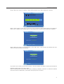
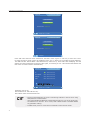
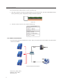
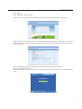
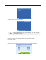
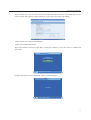
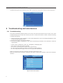
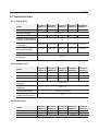
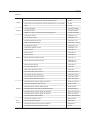
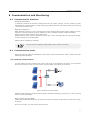
Communication and Monitoring 8 Communication and Monitoring 8.1 Communication Interface Standard configuration: 1. Ethernet: Transmit the inverter working state such as output voltage, current, frequency, fault information to the PC machine or other monitoring system. Ethernet can achieve multi-inverter wired network at the same time. Optional configuration: WIFI: Wireless connect to route. Transmit the inverter working state such as output voltage, current, frequency, fault information to the PC machine or other monitoring system. WIFI can achieve multi-inverter wireless network at the same time. RS485: Achieve multi-inverter network to monitor the inverter working state such as output voltage, current, frequency, fault information GPRS: Inform message by message. Only choose one optional configuration when inverter is working. 8.2 Communication mode When user want to know the information of the power system and monitor power system. We offer following communications. 8.2.1 Ethernet communication You can connect inverter to Internet by router (the router is not special for inverters, you can get any brand in the market). Then you can see the inverter’s data in any place of the world. WAN Router Figure 22 Ethernet communication Hardware Requirements: computer which support windows(including xp,vista,win7), router, netting twine, inverter(LAN mode). Monitor mode: LAN and WAN. LAN: Install SolarPower Browser in PC which can monitor inverters .In this mode, you can use a router or nonuse. If you use a router, you can monitor 254 inverters. 27 Communication and Monitoring Parameter setting when using router: Step 1˖Enter home interface automatically after startup (If not the home interface, press “ESC” return to the home interface). 2012-03-03 10 : 00 : 00 Home Power kwh 0.0 W Today Total t 208.4 V 205.9 V 0.0 KWh 0.0 KWh 1.045 kw = ~ 49.99 Hz Press Esc to Main Menu Step 2: Press “ESC” in home interface then enter the main menu. 2012-03-03 10 : 01 : 00 Main Menu Instantaneous values History Event List Settings System Info Press Esc to Home Step 3: Move the cursor to "settings" and then press “OK”, will enter settings interface. Settings 2012-03-03 10 : 02 : 25 Language Input config Date/Time Reset Password Clear date Network Clear events AutoTest(Italy) LCD contrast Factory set Country Safety param Press Esc to Main Menu 28 Communication and Monitoring Step 4: Move the cursor to "network", press "OK" and then enter "Input Password" interface. 2012-03-03 10 : 03 : 10 Input Password Please input customer password 0 Left/Right : Move Selection Up/Down : Increase/Decrease value Press Esc to Settings Step 5: Press "right" or "left" key to move the cursor to select the figure which need to be modified. Press "up" or "down" key to modify figure. If the password is correct will enter 'Ethernet" interface. Ethernet 2012-03-03 10 : 16 : 23 Auto-IP/DHCP Manual-IP Current mode: Auto-IP/DHCP Press OK to confirm Step 6: Move the cursor to "Auto-IP/DHCP", press "OK" twice. LCD interface will Reboot and then enter into home interface automatically. Ethernet 2012-03-03 10 : 16 : 40 Auto-IP/DHCP Manual-IP Current mode: Auto-IP/DHCP Confirm? If you don’t use a router, you can only monitor 1 inverter. Need to use cable to connect inverter with PC. Parameter setting when not using router: Refer to settings when using router:Main Menu->Settings->Network->Ethernet. In "Ethernet" interface move the cursor to "Manual-IP", press "OK" twice(one press to confirm). 29 Communication and Monitoring Ethernet 2012-03-03 10 : 22 : 23 Auto-IP/DHCP Manud-IP Current mode: Manual-IP Press OK to confirm Ethernet 2012-03-03 10 : 22 : 50 Auto-IP/DHCP Manud-IP Current mode: Manual-IP Confirm? Press "OK" twice then will enter "Manual-IP" interface. Press "right" or "left" key to move the cursor to select the figure which need to be modified. Press "up" or "down" key to modify figure(IP Address˖ 192.168.000.002. Subnet Mask˖255.255.255.000, others are 0). Press “OK” after modifying. LCD will display the setting parameter and press “OK” again, now setting is over. LCD interface will Reboot and then enter to home interface automatically. Manual-IP 2012-03-03 10 : 26 : 05 IP: 192.168.000.002 SubnetMask: 255.255.255.000 Gateway: 000.000.000.000 DNS: 000.000.000.000 Left/Right : Move Selection Up/Down : Increase/Decrease value Press OK to confirm Parameter set for PC: Set IP address as 192.168.000.001, Set Subnet mask as 255.255.255.000. ķ Need to install SolarRiver-D inverter monitoring software in the PC when using WIFI, Ethernet communication. ĸ Can’t using RS485 and Ethernet communication mode for a PC at the same time. Ĺ The default set is “Auto IP”. If use router, LAN or WAN monitor is available without any parameter setting. ĺ In WAN mode, must use router and recommend to select auto IP mode. 30 Communication and Monitoring 8.2.2 RS485 Communication RS485 is generally for at most 32 inverters communication at the same time. But the length of communication wire should be1200m. You can read and analyse data by PC if the system is equipped with Solar-Log200/500/1000. Please refer to Solar-Log200/500/1000 manual for more information. Figure 23 RS-485 jack Two types of cable must be prepared before using Solar-Log to monitor mult-inverters. The communication cable between inverter and inverter: 1. Prepare two 8-PIN RJ45 modular plug, hold the RJ45 modular plug with the 'clip' on the bottom, the 'opening' (where you insert the cable) facing you, the order number is 1 to 8 from left to right, as figure 24. T-568B Pin 1 1 2 3 4 5 6 7 8 RJ-45 Plug O/ O G/ B B/ G Br/ Br Figure 24 2. Use a length of communication cable, then push the 8 color wires into the modular plug follow the same order as below. 1 orange white 2 orange 3 green white 4 blue 5 blue white 6 green 7 brown white 8 brown 3. Then put the both ends of communication cable into the communication ports of inverter respectively. If there are N inverters, need N-1 this communication cable. 31 Communication and Monitoring The communication cable between inverter and Solar-Log: 1. One side of cable is the same as cable between inverter and inverter, the other side remains 4 colour wires: green white, green, orange white, orange, as shown in figure 25. Figure 25 2. Connect 4 colour wires to 1,4,5,6 port of Solar-Log. 1 green white 2 reserve 3 reserve 4 green 5 orange white 6 orange 8.2.3 WIFI communication You can connect inverter to Internet by router. Then you can see the inverter’s data in any place where internet is available. WAN Router Figure 26 WIFI communication OS: win xp, Vista, Win7; Network: Lan or Wan; Wifi: 802.11g. 32 Communication and Monitoring WIFI settings: Note˖Appendix is WIFI route list. Step1: Connect a cable following the steps of Ethernet before opening "SolarPower Browser". Step2: Double-click name of inverter to enter detail information page. Set the SSID of router which WIFI is going to be connected to and input the password(known from installation contractor) then save these information. Step3˖Reboot the computer automatically and disconnect netting twine connection. Step4˖Check WIFI information: Enter the interface successively: Main Menu->Settings->Network, move the cursor to "WIFI" and press "OK". 2012-03-03 10 : 27 : 23 Network Ethernet WIFI Press OK to confirm 33 Communication and Monitoring The GUI bellow tells the WIFI hasn’t been set yet. 2012-03-03 10 : 28 : 10 Wifi Link Name: Press ESC to Back If WIFI has been set, shown as following figure. 2012-03-03 10 : 28 : 50 Wifi Link Name: BAFFAL0-5D8959 Press ESC to Back Hardware Requirements: routerǃinverter equipped with WIFIǃPC˄with SolarPower Browser software˅ 8.2.4 GPRS communication GPRS function is that sends fault message to user when inverter is at fault. Hardware Requirements: SIM card, inverter equipped with GPRS, mobile telephone. Monitor mode: message. GPRS settings: Step1: Use mobile telephone to set PIN code of SIM card which will be installed in inverter. Step2: Connect cable following the steps of Ethernet before opening "SolarPower Browser". 34 Communication and Monitoring Step3: Double-click name of inverter then enter detail information interface. Set the PIN code, service center number and customer mobile telephone number then save these information. Step4: Reboot the computer automatically. Step5: Check GPRS information: Enter the interface successively: Main Menu->Settings->Network, move the cursor to "GPRS" and press "OK". 2012-03-03 10 : 27 : 23 Network Ethernet GPRS Press OK to confirm If GPRS setting has not been initialised, shown as following figure. 2012-03-03 10 : 29 : 10 GPRS Message No settings Press ESC to Back 35 Communication and Monitoring & Troubleshooting and maintenance If GPRS setting has been initialised, press "OK" to check the information, shown as following figure. GPRS Message 2012-03-03 10 : 32 : 06 PIN 1234 Center Number: +8613800510500 Customer Number: +8615000000000 Press OK to have a test! Press ESC to Back 9 Troubleshooting and maintenance 9.1 Troubleshooting This section illustrates possible faults of an inverter and solving methods and provides users with troubleshooting tips to help them identify and solve common problems. Please read the following troubleshooting steps: 1. Check the warning, fault messages or fault codes displayed on LCD. If a message is displayed, record it before doing anything further. 2. Attempt the solution according to table 5. 3. If no fault message is displayed on LCD, check the following list whether the installation meet the requirements. — — — — — Is the inverter installed in a clean, dry, adequately ventilated place? Have the DC input switch been opened? Do section area and length of cable meet requirements? Are the input and output connections and wiring in good condition? Are the configuration settings correct for user particular installation? Steps of checking the warning and fault information displayed on LCD: Move the cursor to the "Event list" and then press “OK” in main menu interface, then enter "Event list" interface. Events list Code 40 10 09 08 08 2012-03-03 10 : 42 : 07 Message Bus over voltage 2012-03-03 10 : 40 : 36 PV2 over voltage 2012-03-03 10 : 40 : 34 PV1 over voltage 2012-03-03 10 : 40 : 34 No utility 2012-03-03 10 : 40 : 22 No utility 2012-03-03 10 : 40 : 14 01/20 Press ESC to Main Menu Figure 27 Event list interface 36 Troubleshooting and maintenance When SolarRiver-D inverter is at fault, the fault information is composed of code, occurring time and fault description. Please contact Samil Power Co.,Ltd for further technical assistance. Please provide detailed installation information and inverter model, serial number and fault information. Table 5 Troubleshooting list Faults Grid volt / freq over / underrating Diagnosis and Solutions -Wait grid go back to normal working state. -Mak sure that grid voltage and frequency complies with standards. -Or, please ask for help No Utility -Check grid-connection -Or, please ask for help. PV1/PV2 over voltage -Check the PV open-circuit voltage whether it is >Max.DC voltage. -Or, please ask for help. DCI out range - Wait for one minute. -Or, please ask for help. SCI/ SPI communication fault -Disconnect DC and AC side, and connect them again. -Or, please ask for help. PV1/PV2 isolation fault -Check the impedance among PV (+) PV (-) and grounding whether they are>600Kohm. -Or, please ask for help. Consistent Fault -Disconnect DC and AC side, and connect them again. -Or, please ask for help. Relay Failure -Disconnect DC and AC side, and connect them again. -Or, please ask for help. GFCI over 30mA /60mA / 150mA /300mA fault -Check whether leakage current is too high. -Disconnect DC and AC side, check the surrounding equipment on the AC side. -Reconnect the input side and check inverter after troubleshooting. -Or, please ask for help. EEPROM read/ write failure -Disconnect DC and AC side, and connect them again. -Or, please ask for help. Bus over voltage -Disconnect DC side, and connect them again. -Check L line and N line whether it has connection faults. -Or, please ask for help. GFCI device failure -Disconnect DC and AC side, and connect them again. -Or, please ask for help. Input/ output current high -Disconnect DC and AC side, and connect them again. -Or, please ask for help. 37 Troubleshooting and maintenance & Decommissioning 9.2 Daily maintenance Inverters generally do not need any maintenance or calibration, but ensure air-cooling fin not be covered by any dust or dirties. Inverter cleaning Please use electric drier, soft dry cloth or brush to clean inverters. Water, corrosive chemical substance or intense cleaning agent are not allowed to clean the inverter. Cooling fin cleaning To ensure inverter good performance and long-period usage, cooling fin needs to be left with adequate space. Please use electric drier, soft cloth or brush to clean cooling fin. Water, corrosive chemical substance or intense cleaning agent is not allowed. 10 Decommissioning 10.1 Decommissioning steps 1. Switch off the AC grid; 2. Switch Off the DC switch; 3. Wait 5 minutes; 4. Release the DC connectors; 5. Release the AC connectors. Now inverters can be demounted safely. 10.2 Package Please pack the inverter with the original package as far as possible. If original package is not available, use an equivalent carton that meets the following requirements: 1. Load more than 50 kg; 2. With handle; 3. Can be fully sealed off. 10.3 Storage Store the inverter in dry place where temperatures are between -25 °C - +70 °C. 10.4 Disposal Please deliver inverters and packing materials to a suitable space where should meet disposal regulations for electronic scrap at the end of its service. 38 Technical Data 11 Technical Data 11.1 Input (DC) Model Max.PV power[W] SolarRiver 3400TL-D SolarRiver 4000TL-D SolarRiver 4500TL-D SolarRiver 5000TL-D SolarRiver 5200TL-D 3400 4000 4500 5000 5200 15/15 15/15 Max.DC voltage[V] Max.input current[A] 550 10.5/10.5 12/12 13.5/13.5 Number of MPP trackers /strings per MPP tracker Max power of Track1/ Track2[W] MPP voltage range (at rated power)[V] 2/1 2200/2200 2500/2500 2750/2750 3000/3000 3100/3100 160~500 165~500 165~500 175~500 175~500 DC Switch optional Shutdown voltge/Start voltage[V] 60/100 11.2 Output (AC) SolarRiver 3400TL-D SolarRiver 4000TL-D SolarRiver 4500TL-D SolarRiver 5000TL-D SolarRiver 5200TL-D AC nominal power[W] 3000 3680 4000 4600 4600 Max.AC power[W] 3200 3680 4300 4600 5000 Max.AC current[A] 16 16 22 23 24 SolarRiver 5000TL-D SolarRiver 5200TL-D Model Nominal AC voltage/ range[V] 230/180~270 AC grid frequency/ range[Hz] 50/47~52 Power factor(cosij) 0.8lagging~0.8leading Total harmonic distortion (THDi)(at nominal power) <3% 11.3 Efficiency Model SolarRiver 3400TL-D SolarRiver 4000TL-D SolarRiver 4500TL-D Max.efficiency 97.4% 97.6% 97.6% Euro efficiency 96.5% 97.1% 97.1% MPPT efficiency 97.6% 97.6% 97.1% 97.1% 99.9% 39 Technical Data & Guarantees 11.4 General data Model Dimensions(W/H/D) [mm] Weight [kg] Operating temperature range [°C] Ingress protection Topology Internal consumption (night) [W ] Cooling concept Noise (typical) [dB] LCD display Communication Standard warranty [year] SolarRiver 3400TL-D SolarRiver 4000TL-D SolarRiver 4500TL-D SolarRiver 5000TL-D SolarRiver 5200TL-D 520 / 380/ 175 26 -20~+60 IP65 tansformerless <3 Convection <30 3.5inch TFT LCD Ethernet optional for RS485/GPRS/WiFi 5 12 Guarantees Samil Power Co., Ltd offers 5 years warranty service for SolarRiver-D inverter. Warranty period is from the date of installation. But the longest period don’t exceed 66 months from the date of delivering goods. During the warranty period, Samil Power Co., Ltd guarantees normal function of the SolarRiver-D inverter. If there are faults within our responsibility, we will provide maintenance free of charge. During the warranty period, if inverter appears malfunction or fault, please contact your dealer or installation contractor. 40 The followings are not included in the scope of warranty: ¥ Use SolarRiver-D inverter for other purpose; ¥ Install incorrectly or not conform to the rule; ¥ Improper operation ¥ Useunqualified protection when working; ¥ Modify the equipment without authority; ¥ Damage because of external factors or the majeure force(such as lightning, over-voltage, bad weather, and fire, earthquake, tsunami and so on); ¥ Poor ventilation; ¥ Don’t comply with the relevant safety regulations; ¥ Transportation damage. Guarantees Appendix Apple Corega Belkin Buffalo Cisco Linksys AirPort Express with 802.11n A1264 AirPort Extreme Simultaneous dual-band 802.11n A1301 AirPort Extreme Simultaneous dual-band 802.11n (Late 2009) A1354 Apple A1143 CG-WLR300NNH CG-WLR300NNH CG-WLR300NM CG-WLR300NM IEEE802.11b/g/n Wireless Broadband AP/Router CG-WLR300GNE N Wireless Router F5D8236-4 v2 N+ Wireless Router F5D8235-4 v2 Enhanced Wireless Router F6D4230-4 v2 Belkin N Wireless Router F5D8236-4 v3000 N+ Wireless Router F5D8235-4 v3 N Wireless Modem Router F5D8636-4 v2 Belkin Router F7D3302 v1 Belkin Router F7D4302 v1 Belkin Router F7D4301 v1 Belkin Wireless Modem Router F7D1401 v1 Belkin Wireless Modem Router F7D2401 v1, F7D2401-B v1 Belkin Modem Router F7D3402 v1 Surf Wireless Router F7D2301 Share Max Wireless Router F7D3301 Surf N300 Wireless N Router F7D2301 V3000 Surf N300 Wireless N Router F7D6301 V3000 Connect N150 Wireless Router F7D5301 V3000 Connect N150 Wireless Router F7D1301 V3000 BUFFALO Nfiniti Router WHR-HP-G300N WHR-HP-G300N BUFFALO AirStation WHR-HP-GN WHR-HP-GN BUFFALO Nfiniti Router WHR-G301N WHR-G301N BUFFALO Nfiniti Accesspoint WLAE-AG300N WLAE-AG300N BUFFALO Nfiniti Router WZR-HP-AG300H WZR-HP-AG300H BUFFALO Nfiniti Router WZR-HP-G302H WZR-HP-G302H BUFFALO-WZR-AMPG144NH WZR-AMPG144NH Wireless-N Gigabit Router WRT310Nv2 Wireless-N Home Router WRT120N Wireless-N Access Point with Dual-Band WAP610N Dual-Band Wireless-N Gigabit Router E2000 41 Guarantees Wireless-N Broadband Router E1000 Wireless-N Broadband Router M10 Wireless-N Gigabit Router M20 Wireless-N Broadband Router E1000(v2.1) Wireless-N Gigabit Router M20 Dual-Band Wireless-N Gigabit Router E2000 Wireless-N Broadband Router E1000(v2) Wireless-N Broadband Router M10(v2) Linksys WRT54G v8 Cisco AIR-AP1231G-A-K9 AIR-AP1231G-A-K9 Linksys WRT54 WRT54 G2 v1 Cisco Aironet Aironet 1200 Cisco Controller AP 1130G Cisco Controller 1242AG IEEE 802.11 b/g/N Wireless Router / DIR-605 DIR-605 D-Link DIR-615 Wireless N Router DIR-615E3/E4 IEEE 802.11 b/g/N Wireless Router /DIR-605.B2 DIR-605.B2 WIRELESS N 150 HOME ROUTER / DIR-600 V.B4 DIR-600 V.B4 DIR-815 Wireless N Dual Band Router / DIR-815 v1.00 DIR-815 v1.00 Wireless N 8 port router DIR-632 IEEE 802.11 Wireless N 150 Home Router / DIR-501 DIR-501 IEEE 802.11 Wireless N Router / DIR-515 DIR-515 IEEE 802.11a/b/g/n wireless Access Point / DAP-2690 DAP-2690 IEEE 802.11 b/g Mobile Wireless Router / DIR-412 DIR-412 Dlink G730AP v2 G730AP v2 IO Data I-O DATA WN-G54/DCR WN-G54/DCR Motorola Symbol AP-5131 AP5131 Aterm WR4100N WR4100N NEC PA-WR8170N-HP PA-WR8170N-HP NEC PA-WR8700N-HP PA-WR8700N-HP Wireless-N 300 Router JWNR2000 Wireless-N 150 Router WNR1000v2 Wireless-N 300 Router WNR2000v2 Wireless-N 150 Router WNR612v2 N150 Wireless Router WNR1000v3 N150 Wireless Router WGR614v10 Powerline AV 200 Wireless-N Extender XAVN2001 XAVN2001 N300 Wireless Router with USB WNR2200 D-Link NEC Netgear 42 Guarantees ProSafe Dual Band Wireless-N Access Point WNDAP350 ProSafe Wireless-N Access Point WNAP320 WGR614 v9 WGR614 v9 Orinoco AP-700 Orinoco AP-700 Proxim ORiNOCO AP-600 150Mbps Wireless Lite N Router TL-WR740N 150Mbps Wireless Lite-N Router TL-WR741ND 300Mbps Wireless N Router TL-WR841N TP-LINK Wireless N Access Point TL-WA901ND TP-LINK 300Mbps Wireless N Access Point TL-WA801ND Planex-MZK-MF300N MZK-MF300N Proxim TP-Link Planex 43 SAMIL POWER CO., LTD. Marketing & Sales Office Factory Add: No.52,Huigu Innovation Park, Huishan District, Wuxi,Jiangsu Province,P.R.China 214174 Add: Tel: +86 510 83593131 Fax: +86 510 81819678 E-mail:[email protected] http://www.samilpower.com No.66 Taihangshan Road, Suyu Economic Development Zone, Suqian City, Jiangsu Province, P.R.China Tel: +86 527 88754666 Fax: +86 527 84453877 223800