1
High Performance Ventilation Equipment
PRO-C Series
Energy Recovery Ventilator
For Carrier® HJ, TM and TF Rooftops
(Sizes 3 to 12.5 ton)
Technical Guide
PRO-C-1000
PRO-C-2400
Table of Contents
PRO-C Series Energy Recovery Module...................................................................................................................................... 1
Preconditioning and Good IAQ.................................................................................................................................................... 1
Humidity Control and IAQ ............................................................................................................................................................ 1
How It Works ................................................................................................................................................................................... 1
Applying the PRO-C ....................................................................................................................................................................... 2
Benefits .............................................................................................................................................................................................. 2
Features .............................................................................................................................................................................................. 3
Selection Procedure ......................................................................................................................................................................... 4
Fan Tables ......................................................................................................................................................................................... 6
Unit Arrangement & Dimensions ................................................................................................................................................. 7
P RO-C S e r i e s
Electric Preheat Layout ................................................................................................................................................................... 8
3Ø Circuit Diagram, PRO-C-1000 ................................................................................................................................................ 9
3Ø Circuit Diagram, PRO-C-2400 .............................................................................................................................................. 10
1Ø Circuit Diagram ....................................................................................................................................................................... 11
3Ø Electric Preheat Frost Protection Circuit Diagram ........................................................................................................... 12
1Ø Electric Preheat Frost Protection Circuit Diagram ........................................................................................................... 12
Electrical Data ................................................................................................................................................................................ 13
Full Load Power Draw .................................................................................................................................................................. 14
Electrical Preheat Data .................................................................................................................................................................. 14
Order Summary Sheet ................................................................................................................................................................... 15
Sample Specifications .................................................................................................................................................................... 16
©
2001-2006 ERV Systems. All rights reserved.
The information in this technical guide is furnished for informational use only, is subject to change without notice, and should
not be construed as a commitment by ERV Systems. ERV Systems assumes no responsibility for any errors that may appear in
this technical guide.
No part of this publication may be reproduced, stored in a retrieval system or transmitted, in any form or by any means, electronic,
mechanical, recording, or otherwise, without the prior written permission of ERV Systems.
ERV Systems and the ERV System’s logo are registered trademarks.
Carrier, Weathermaker and Weathermaster are trademarks of Carrier Corporation.
i
Humidity Control and IAQ
The PRO-C Series Energy Recovery Ventilator is an
outdoor air preconditioner specifically designed to reduce
the energy required to cool or heat the outdoor air by as
much as 80 percent. The PRO-C also allows the Carrier®
3 through 12.5 ton HJ, TM, and TF rooftop air-conditioner
systems to effectively and economically accommodate the
three-to-four fold increase in outdoor air quantities, which
is recommended by the ASHRAE Standard 62, Ventilation
for Acceptable Indoor Air Quality. This unique capability allows
both new and existing buildings to benefit from healthy
indoor environments.
The PRO-C is designed to improve humidity control
when combined with the Carrier rooftop equipment. Because
the unit preconditions the incoming air to the packaged
equipment, the required refrigeration capacity can be reduced
by as much as 50 percent. Thus, the costs of the PRO-C
and its installation are typically offset by the reduced size of
the Carrier system. Generally, any first cost premium is paid
back within the first year of operation.
Unitary air conditioner and heat pump units are
controlled by temperature. When space conditions are
satisfied, the cooling coil or heating source is cycled off.
Since the ASHRAE Standard 62 recommends the continuous
supply of outdoor air, then warm/humid (cooling mode) or
cool/dry (heating mode) outdoor air is dumped directly into
the occupied space during those times.
As the outdoor air load changes, humidity levels can
fluctuate significantly with unitary HVAC equipment and heat
pumps. To achieve an acceptable indoor environment, space
humidity conditions should be maintained between 30 and
60 percent relative humidity. The probability of microbial
problems, i.e., mold growth, is greatly enhanced at 70 percent
relative humidity and above.
Preconditioning and Good IAQ
ASHRAE Standard 62 defines the minimum outdoor
air ventilation rate required to achieve acceptable indoor air
quality. This standard, which is incorporated in all the U.S.
model building codes (BOCA, Southern, and Uniform),
recommends that outdoor air quantities be increased from 5
cfm per person to 15 to 20 cfm per person to avoid adverse
health effects. The increased ventilation air rates concern
many owners, architects, and engineers with regard to their
impact on humidity control, operating costs and construction
costs.
By recovering up to 80 percent of the total energy
normally exhausted from facilities, the PRO-C provides an
effective solution to the ventilation mandate. When a PROC is combined with a Carrier rooftop unit, it allows for a
three-to-four-fold increase in the outdoor air quantity (5 to
20 cfm/person) without an increase in operating costs.
If a facility is designed to include unitary packaged
HVAC equipment or heat pumps, the addition of a PRO-C
is especially beneficial. In addition to reducing the cost of
operation, the PRO-C system greatly improves humidity
control; something that is important for providing acceptable
indoor air quality.
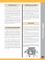
How It Works
The PRO-C Series is a packaged system, which includes
supply and exhaust air fans, outdoor and return air filter and
a TEC total energy recovery wheel. The TEC wheel recovers
both sensible (temperature) and latent (moisture) energy; it
cools and dehumidifies the outdoor air during the cooling
season, while heating and humidifying the outdoor air in the
heating season.
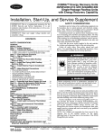
The TEC wheel utilizes a fluted aluminum substrate,
which is uniformly coated with a fast-acting, adsorbent
desiccant. As the transfer media slowly rotates between the
outdoor and exhaust airstreams, the higher temperature air
gives up its sensible energy to the aluminum. This energy is
then given up to the cooler airstream during the second half
of the revolution. (See Figure 1.)
Just as the temperature is captured and released, so is the
moisture. TEC’s desiccant coating has an enormous internal
surface area and a strong attraction for water vapor. Since the
opposing airstreams have different temperature and moisture
contents, their vapor pressures differ. This difference causes
the transfer of latent energy.
P RO-C S e r i e s
The PRO-C Series
Figure 1. An inside view of the PRO-C ventilator with typical
operating conditions during the cooling (C) and heating (H)
season respectively.
Outdoor Air
(C) 95°F, 110 gr/lb
(H) 5°F, 4 gr/lb
Supply Air
(C) 80°F, 76 gr/lb
(H) 54°F, 25 gr/lb
Exhaust Air
(C) 90°F, 99 gr/lb
(H) 21°F, 9 gr/lb
Return Air
(C) 75°F, 65 gr/lb
(H) 70°F, 32 gr/lb
1
P RO-C S e r i e s
Applying the PRO-C Series Unit
The PRO-C Series has supply and return connections
located on the side of the unit and is designed to mate up
to the selected Carrier rooftop air-conditioner. The PRO-C
is designed for outdoor installation, has a high level of total
recovery effectiveness and includes a single-point electrical
connection.
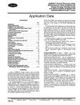
In a typical application, the PRO-C pulls exhaust air
directly from the return air section of the Carrier unit.
Preconditioned outdoor air is then provided directly to the
cooling coil, mixing with the recirculated airstream. The
PRO-C unit and Carrier’s supply fans run continuously
while occupants are in the conditioned space, even when the
heating or cooling coils are off. This provides a continuous
supply of outdoor air, therefore meeting the ASHRAE
Standard 62 guidelines.
A key advantage to this approach is that no additional
ductwork is required beyond that which is already provided
for the Carrier unit. This simplifies the installation process
and minimizes project first cost. This approach also
simplifies retrofit applications where it is desirable to increase
the amount of outdoor air supplied to a space without
replacing the existing HVAC system.
Figure 2. PRO-C Series typical installation.
Exhaust Air
Return Air
to be Exhausted
Outdoor Air
Supply Air
to Carrier
Economical Compliance
with ASHRAE Standard 62
To achieve acceptable indoor air quality, ASHRAE
Standard 62 recommends a three-to-four-fold increase in
the amount of outdoor air provided to most facilities. In
addition, the ASHRAE Standard recommends that this
increased outdoor air quantity be introduced continuously
while spaces are occupied. By recovering up to 80 percent of
the total energy normally exhausted from occupied spaces,
the PRO-C enables the Carrier unit to effectively handle this
increase in outdoor air load without the need for a larger
sized package and without increasing energy consumption.
Improved Cooling
Season Humidity Control
Operation of conventional HVAC systems is governed
by a thermostat, i.e., in response only to the conditioned
space temperature. When the cooling coil is cycled off,
the outside air fan is typically shut-off as well. Thus, no
ventilation is provided to the conditioned space until the
thermostat calls for cooling. If the outside air fan is allowed
to run while the cooling coil is off, then warm, humid air is
directed to the space. In both of these cases, indoor space
humidity levels will increase above guideline levels, i.e., 60
percent relative humidity.
Since the PRO-C unit dehumidifies and cools the
incoming outdoor air, the supply air conditions are close to
the return air conditions. This effectively produces a buffer
against high outdoor latent loads resulting in acceptable
indoor humidity levels.
Helps Reduce Humidification
Requirements During the Heating Season
Supplying 15 to 20 cfm/person of cold, dry outdoor
air to a facility during the heating season can result in
unacceptably low indoor relative humidity. Most facilities
require humidification, which is costly to operate and
maintain. The PRO-C unit captures the moisture generated
within the space to provide free humidification during the
heating season, therefore maintaining a healthier indoor
environment.
In moderate climates with short heating seasons, this
may be sufficient to completely eliminate the need for any
humidification equipment.
Benefits
2
Reduced Equipment First Cost
Improves the Comfort
of Occupied Spaces
Without the addition of effective energy recovery, the
capacity of HVAC systems must be increased greatly to
handle the greater outdoor air loads. Increasing equipment
size often requires the addition of reheat and sophisticated
control sequences to control both humidity and temperature.
The PRO-C often reduces project first cost by allowing a
smaller Carrier unit and duct system to be used, without the
need for reheat or complex controls.
As outdoor air is supplied to the space, the heating/
cooling source is cycled on and off to maintain temperature.
When it is cycled off, very cold or very warm/humid air can
be “dumped” on the occupants, causing wide temperature
fluctuations, which makes for a very uncomfortable
environment. The PRO-C solves this problem by providing
moderated supply air conditions, even as the Carrier unit is
cycled on and off.
Features
Standard
Optional
1 Novel System Design
• Efficient and economical design
meeting the needs of the conventional
HVAC market.
• Compact, low profile design to conform to typical architectural requirements.
• Easy access to all internal components through a large hinged access
door and removable roof panel.
• Outdoor air inlet and exhaust air
outlet located at opposite ends of
unit.
8 Electric Preheat
4 Supply & Exhaust Fans
• Sized for quiet and efficient
operation.
• Mounted and balanced.
5 Filter Sections
2 TEC Wheel
• Certified total energy (both sensible
and latent) recovery performance.
• Easily removable wheel cassette
module.
• Surpasses NFPA-90A requirements
having a smoke and flame spread rating of 0 and 0, vs. 50 and 25 allowed
by the standard.
• Self-adjusting air seals.
• Filtration provided for both the
outdoor air and return air.
• Galvanized steel cabinet
construction.
• Entire cabinet insulated to minimize
energy loss.
• Hinged doors for easy access.
• Floor of the unit built as a pan to
ensure watertight design.
9 Frost Protection
• Thermostatic frost control allows the
entire PRO-C unit to be turned off
at a predetermined temperature when
electric preheat is not desired.
10 Control Options
6 Hoods and Dampers
• Airflow balancing dampers.
• Unit provided with an intake hood
with cleanable filter to limit rain and
snow introduction.
• Exhaust air back draft damper.
7 Electric Package
3 Cabinet Construction
• An electric preheat coil can be
provided to avoid frosting conditions
for installations in cold climates,
which have high indoor humidity
design conditions.
P RO-C S e r i e s
• All motors wired to starters.
• Accepts contact inputs for supply
fan start/stop, wheel start/stop and
unit start/stop.
PRO-C-1000: 208, 240V 1Ø,
208, 240, 480V 3Ø
PRO-C-2400: 208, 240V 1Ø,
208, 240, 480V 3Ø
• Stop/Jog Economizer board allows
the wheel to be stopped automatically
during mild outdoor temperatures
with periodic brief rotation.
• Wheel Frost Protection allows
the wheel only to be stopped by
the stop/jog economizer board at a
predetermined outdoor temperature
• Rotation Detector Sensor can
provide an alarm signal through the
stop/jog economizer board indicating
failure of the wheel rotation.
11 Pedestal Support
• Optional support is adjustable
from 9”-14”.
3
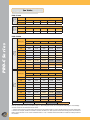
Selection Procedure
The selection of the PRO-C Series is governed by two
parameters: the amount of outside air needed to be preconditioned and the Carrier unit to which the PRO-C is to
be mated shown in Table 1. Only a specific size PRO-C will
mate to a Carrier unit. Nominally, the PRO-C will provide
between 30% and up to 100% of outside air. There is a
limited product combination which will allow 100% outside
air applications.
Table 1. ERV Systems/Carrier Unit Combinations.
P RO-C S e r i e s
Carrier
Weathermaster
Carrier
Weathermaker
Model
Airflow Range
(scfm)
Wheel Face Area
(ft2/side)
PRO-C-1000
450-1110
1.23
PRO-C-2400
800-2600
2.46
Table 3. Unit Effectiveness vs. Wheel Face Velocity.
Wheel Face Velocity (fpm)
Total Recovery
Effectiveness (%)
300
80.3
400
77.8
500
75.3
600
72.8
PRO-C-1000
PRO-C-2400
48/50HJ004
48/50HJ008
48/50HJ005
48/50HJ009
48/50HJ006
48/50HJ012
48/50HJ007
48/50HJ014
48/50TM004
48/50TM008
700
70.3
48/50TM005
48/50TM009
800
67.8
48/50TM006
48/50TM012
900
65.3
48/50TM007
48/50TM014
1000
62.8
48/50TF004
48/50TF008
1100
60.3
48/50TF005
48/50TF009
48/50TF006
48/50TF012
48/50TF007
48/50TF014
Notes:
Refer to Pro Series Models when attaching rooftop units
larger than 12.5 tons (transition required) and when using
as a stand-alone ventilator.
1. Determine Supply Side Recovery Efficiency
Enter Table 2 to determine the recovery wheel face
area per airstream. Divide the smaller volume of the two
airstreams by the wheel area obtained from Table 2 to
determine face velocity. Enter Table 3 for the face velocity of
the smaller airstream to determine the unit base effectiveness
at equal airflows.
If the airflows are not equal, then divide the supply air
volume by the return air volume to determine the airflow
ratio. Using the base effectiveness determined from Table
3 and the calculated airflow ratio, enter Table 4 to obtain
the corrected supply air efficiency for unequal airflow
applications.
Example:
Given a supply airflow of 965 and exhaust airflow of 1015. From
Table 2, the PRO-C wheel area per side is 1.23 sq. ft. Dividing 965
cfm (supply) by 1.23, gives a (supply side) face velocity of 785 ft/min.
From Table 3 the base effectiveness is interpolated at 68 percent. Using
the base effectiveness and an airflow ratio of 0.95 (965cfm/1015cfm)
from Table 4 determines the supply side efficiency to be 70.6 percent.
4
Table 2. Airflow Range and Energy Wheel Area.
Table 4. Unequal Airflow Efficiency Correction.
Ratio of
SA Flow to
RA Flow
68
70
72
74
76
78
80
0.7
82.6
84.0
85.5
87.0
88.5
90.0
91.4
0.8
78.0
79.8
81.5
83.2
84.9
86.7
88.4
0.9
73.2
75.1
77.0
78.9
80.8
82.7
84.7
1.0
68.0
70.0
72.0
74.0
76.0
78.0
80.0
1.1
66.1
67.9
69.6
71.4
73.1
74.8
76.6
1.25
62.4
63.8
65.2
66.6
68.0
69.4
70.8
1.4
58.5
55.9
60.7
61.8
62.9
63.9
65.1
Base Effectiveness
2. Calculate the Supply Air Conditions
Once the design conditions are known and the supply
side efficiency is determined, the temperature and humidity
content of the air supplied to the space can easily be
calculated by using Equation 1. Using dry bulb temperatures
in Equation 1 provides the supply air temperature. The
supply air humidity level is also determined in Equation 1 by
using grains of moisture or humidity content (lb. moisture/
lb. dry air). The enthalpy of the supply air can be calculated
in the same manner. Do not use equation 1 to calculate the
wet bulb temperature.
wSA = (110 gr/lb - .706 (110 - 65)gr/lb) = 78 gr/lb
Winter outdoor air design conditions are 5°F, 4 gr/lb with a
return air condition of 70°F, 32 gr/lb.
The winter supply air temperature and humidity level is calculated
in the same fashion to give a condition of 51°F and 24 gr/lb.
Equation 1. Calculating supply, outdoor, and return air
temperatures and moisture contents.
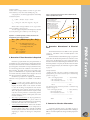
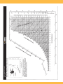
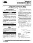
Example 1:
The return air condition is 70°F and
25% relative humidity (27gr/lb).
Line RA 1-OA: No frosting occurs at full recovery
50
Example 2:
The return air condition is 70°F and
35% relative humidity (38 gr/lb).
Line RA2-OA: Frosting occurs at full
recovery at exhaust air condition EA2.
Therefore, frost preheat is required
to bring the outside air to condition OA 2.
Return Air RA 2
40
Return Air RA1
30
38
27
20
Exhaust Air EA2
10
Outside
Air OA1
Outside Air OA 2
0
XSA = {XOA - (EfficiencySA ) (XOA - XRA)}
60
Humidity Ratio
TSA = (90°F - .706 (90 - 75)°F) = 79.4°F
Figure 3. Using the psychrometric chart to determine the
need for preheat frost control.
(grains of moisture per pound of dry air)
Example continued:
Summer outdoor air design conditions are 90°F, 110 gr/lb with a
return condition of 75°F, 50% relative humidity (65 gr/lb.)
Using Equation 1, the summer supply temperature and humidity
is calculated as follows:
-10 -5
10
1.5
20
30
40
50
20.2
60
80
70
Dry Bulb Temperature (°F)
where
X
Indices
SA = supply air
OA = outside air
RA = return air
3. Determine if Frost Protection is Required
Plotted on a psychrometric chart, the performance of
an enthalpy recovery wheel will form a straight line between
the outdoor air and return air conditions. If this line does not
pass through the saturated line on the psychrometric chart,
or if the leaving exhaust air condition of the wheel is not
below freezing, the wheel will not frost. In general, if the
space is not humidified above 30 percent relative humidity
on extreme winter days and the outdoor design is above 0°F,
then frost protection is probably not required.
Should frost protection be required, three different
methods of frost protection are available on the PRO-C
units.
•
Preheat is used as the primary method of frost
protection for the energy wheel in PRO-C units. This
employs an electric heater on the outdoor air intake
to raise the incoming air temperature such that the
operating line of the wheel no longer hits saturation.
This is the preferred method since it requires usually
only about 10°F of preheat to avoid frosting and the
wheel continues to operate at full capacity even at the
extreme conditions.
•
The stop/jog economizer can be programmed to
stop the wheel rotation below a preset outdoor air
temperature. This has the disadvantage of introducing
untreated, cold outdoor air to the Carrier unit.
•
A frost protection thermostat which turns the PROC unit off below a preset outdoor air temperature is
the third available option. This is generally considered
the least attractive solution since it results in the unit
supplying no outdoor air during low temperature
periods.
4. Determine Dimensional & Electrical
Data
The dimensional data for the PRO-C unit is provided
on page 7. The PRO-C unit is mounted adjacent to the
Carrier unit.
The electrical data is determined on page 13, equation 2
and 3. Since the electrical requirements are a function of the
power source, the desired power source (voltage and phase)
must be known before determining this information. If an
electrical preheater is required, the electrical data should be
increased appropriately by the information given in Table
5, page 14.
Example continued:
Assuming that 240V/1Ø power is available, the minimum circuit
ampacity (MCA) for the motors selected in Step 2 is calculated using
equation 2a on page 13.
1.25 * FLA largest fan motor
= 8.6 (1.25*6.9)
+ FLA other fan motor
= 6.9
+ FLA wheel drive/accessories
= 1.1
-----------------------------------------------------------MCA
= 16.6
The maximum circuit overcurrent protection is calculated using
Equation 3 on page 13.
2.25 * FLA largest fan motor
= 15.53 (2.25*6.9)
+ FLA other fan motor
= 6.9
+ FLA wheel drive/accessories
= 1.1
-----------------------------------------------------------MOP
P RO-C S e r i e s
= dry bulb temperature in °F
-or- humidity content in gr/lb.
-or- enthalpy in Btu/lbs.
= 23.53
5. Summarize Selection Information
A selection summary sheet is provided on page 15
which helps organize the performance data when ordering an
PRO-C unit and simplifies the design schedule preparation
process.
5
Fan Tables
Exhaust
Fan Data
Supply
Fan Data
PRO-C-1000
External Static Pressure (in.wg.)*
Airflow (scfm)
-0.3
-0.1
0.1
0.3
0.5
1110
1035
965
885
805
External Static Pressure (in.wg.)*
Airflow (scfm)
-0.3
-0.1
0.1
0.3
0.5
1235
1235
1135
1015
890
All motors 1/2hp, 1,625 rpm
PRO-C-2400
Airflow (scfm)
-0.3
-0.1
800
.15/516
.15/651
1000
.15/579
1200
0.1
0.3
0.5
.15/785
.15/919
.24/1025
.15/734
.15/889
.24/1008
.43/1113
.15/670
.15/872
.26/1007
.46/1114
.64/1219
1400
.15/881
.31/1024
.50/1132
.70/1233
.86/1307
1600
.38/1058
.58/1168
.78/1259
.95/1337
1.09/1415
1800
.68/1218
.89/1302
1.07/1385
1.22/1468
1.40/1536
2000
1.03/1366
1.21/1456
1.39/1526
1.65/1591
1.85/1656
2200
1.41/1529
1.69/1590
1.92/1653
2.11/1715
2.32/1777
2400
2.01/1657
2.20/1716
2.40/1774
2.60/1833
2.79/1891
2600
2.50/1778
2.70/1838
2.87/1898
N/A
N/A
Motor Brake Horsepower/RPM
Supply
Fan Data
P RO-C S e r i e s
External Static Pressure (in.wg.)*
External Static Pressure (in.wg.)*
Airflow (scfm)
-0.3
-0.1
0.1
0.3
0.5
Exhaust
Fan Data
Motor Brake Horsepower/RPM
800
.15/497
.15/667
.15/836
.15/979
.15/1089
1000
.15/575
.15/751
.15/925
.15/1036
.15/1145
1200
.15/659
.15/845
.15/989
.15/1098
.33/1207
1400
.15/758
.15/946
.15/1056
.29/1165
.69/1261
1600
.15/887
.15/1019
.24/1129
.67/1235
1.00/1320
1800
.15/987
.19/1098
.64/1208
1.03/1302
1.30/1393
2000
.15/1071
.61/1184
1.06/1287
1.36/1386
1.62/1482
2200
.60/1164
1.07/1276
1.41/1386
1.70/1489
1.98/1577
2400
1.07/1269
1.46/1395
1.79/1502
2.11/1590
2.42/1678
2600
1.52/1417
1.89/1520
2.24/1605
2.57/1686
2.88/1734
Supplied Motor:
0.75 hp, 1725 rpm
1.50 hp, 1725 rpm
2.00 hp, 1725 rpm
3.00 hp, 1725 rpm
Note: For power draw of motors, see Table 5 page 14. When sizing fan motors, it is not required to add purge air or seal leakage
as these corrections are reflected in the fan charts.
6
* Positive statics reference external static pressures that work against the PRO-C unit fan. Negative statics would work with the PROC unit fan. For example, an PRO-C mounted to a Carrier unit with a -0.3” static pressure in the Carrier mixing section would have an
PRO-C supply fan static of -0.3” and an exhaust fan static of +0.3”. All statics internal to the PRO-C module are already included in
the selection.
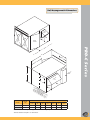
Unit Arrangement & Dimensions
T
US
HA
EX AIR
SU
D
ESS
ACC
NING
OPE
PP
AIR LY
RE
TU
AIR RN
C
B
G
F
L
ICA
TR L
EC
EL PANE
A
P RO-C S e r i e s
*
E
ID
TS
OU AIR
FO
R F RE
AN MO
FO
R F A AC VAB
SE AN C CE LE
RV A CE SS PA
ICE CC SS (P NE
CL ESS DO RO- L
EA (P OR C-1
RA RO
00
NC -C
0)
E = -24
0
24 0)
"
E
Dimensions (inches)
Model#
Net Wt.
(lbs.)
A
B
C
D
E
F
PRO-C-1000
350
30.188
47.875
31.375
11.75
17.0
25.563
14.875
PRO-C-2400
475
38.813
54.750
40.375
13.0
20.0
27.0
21.375
G
Note: Dimensions F & G represent approximate unit center of gravity.
*Service clearance is equal to “C” dimensions.
7
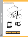
Electric Preheat Layout
P RO-C S e r i e s
R
NE
IO
DIT AL
N
O RIC
EC
T
PR LEC EL
E
N
PA
Pro
-C
Un
it
PR
EH
EA
EC TER
T
PA RICA
NE
L
L
EL
AIR
FL
OW
L
B
W
AIRFLOW
H
A
AIRFLOW
B
C
D
SIDE VIEW
C
PLAN VIEW
Model#
8
Dimensions (inches)
W
H
L
A
B
C
D
PRO-C-1000
24.37
16
14
20
1
2
8
PRO-C-2400
30.5
20.37
14
20
1
2
8
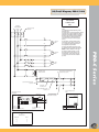
3Ø Circuit Diagram, PRO-C-1000
USE COPPER
CONDUCTORS
ONLY
Line Power
480/240-208/3/60
Disconnect (by others)
*See Note 2
1CR
H3
Supply Fan
Motor
M
Exhaust Fan
Motor
M
Wheel
Motor
H2
2CR
H3
2CR
H1
3CR
H3
3CR
H2
3CR
H1
H2
208/240/480 - 24VAC
40VA UL Cl 2 XFMR
Supply & Exhaust Fan Remote Start/Stop
(by others, factory jumpered)
H1
1
3
2
2
Optional Thermostat Frost Control
*See Note 4
4
2CR
5
2
1
4
1CR
4
3CR
P RO-C S e r i e s
M
1CR
Notes:
1) All dashed lines indicate field wiring unless
otherwise noted.
2) Electric Preheat: If electric preheater is ordered,
the power wiring is factory installed from electric
preheater to Preconditioner Panel and includes a
disconnect at the preheater, (See specifications
and circuit diagram on electric preheater for
information on sizing and connecting supply
power.)
3) Alarm output: One triac-switch to drive a
contactor (by others), 24VAC, 0.3 amps max.
4) If no options are ordered, terminals 1 & 2
are shipped with jumper installed.
5) Remote unit start/stop (by others) may be
any isolated contact, to prevent interconnection
of class 2 outputs, suitable for 24 VAC @ 2
amps.
6) If Relay is ordered, terminals 1 & 2 will
be wired to the N.O. relay mounted on the
electrical panel. Power wiring for the relay
coil is from the Carrier unit and is installed
by others.
Optional Relay
*See Note 4,6
Remote Unit Start/Stop (by others)
*See Note 4,5
5
2
4
Outdoor Air Damper Actuator:
Belimo
Optional Stop/Jog Controller:
Model SMX70
Thermistor Sensor
310-1865 Assembly
RED
BLK
GRN
Wheel Remote Start/Stop
(factory jumpered if optional
SMX70 controller not included)
BELIMO
T2
T1
GRN
L1
4
2
ALARM
5
WHEEL
Optional
Motion Detector Sensor
310-1875 Assembly (observe polarity)
COM
Aux. Rotation Alarm (not used)
(See Note 3)
+
+
1
2
3
BLK
RED
WHT
4
1
2
Tightening Torque
For
Slotted Screws
AWG Size
IN-LB
18-10
20
8
25
6-3
35
9
3Ø Circuit Diagram, PRO-C-2400
Line Power
480/240-208/3/60
USE COPPER
CONDUCTORS
ONLY
Disconnect (by others)
*See Note 2
Notes:
1) All dashed lines indicate field wiring unless
otherwise noted.
2) If electric preheater is ordered, the power
wiring is factory installed from electric preheater
to Preconditioner Panel and includes a disconnect
at the preheater. (See specifications and circuit
diagram on electric preheater for information
on sizing and connecting supply power.)
1CR
H3
1CR
H2
M
Supply Fan
Motor
1CR
H1
3) Alarm output: One triac-switch to drive a
contactor (by others), 24VAC, 0.3 amps max.
4) If no options are ordered, terminals 1 & 2
are shipped with jumper installed.
2CR
H3
2CR
P RO-C S e r i e s
H2
M
5) Remote unit start/stop (by others) may be
any isolated contact, to prevent interconnection
of class 2 outputs, suitable for 24 VAC @ 3.5
amps.
Exhaust Fan
Motor
2CR
H1
6) If Relay is ordered, terminals 1 & 2 will
be wired to the N.O. relay mounted on the
electrical panel. Power wiring for the relay
coil is from the Carrier unit and is installed
by others.
3CR
H3
3CR
H2
M
Wheel
Motor
3CR
H1
H2
208/240/480 - 24VAC
75VA UL Cl 2 XFMR
Supply Fan Remote Start/Stop
(by others, factory jumpered)
H1
1
3
2
2
Optional Thermostat Frost Control
*See Note 4
4
1CR
4
2CR
1
2
5
Optional Relay
*See Note 4,6
4
3CR
Remote Unit Start/Stop (by others)
*See Note 4,5
Wheel Remote Start/Stop
(factory jumpered if optional
SMX70 controller not included)
2
5
4
Outdoor Air Damper Actuator:
Belimo
Optional Stop/Jog Controller:
Model SMX70
Thermistor Sensor
310-1865 Assembly
RED
BLK
GRN
T1
GRN
L1
4
2
ALARM
5
WHEEL
Optional
Motion Detector Sensor
310-1875 Assembly (observe polarity)
COM
Aux. Rotation Alarm (not used)
(See Note 3)
Tightening Torque
For
Slotted Screws
10
BELIMO
T2
AWG Size
IN-LB
18-10
20
8
25
6-3
35
4
1
2
+
+
1
2
3
BLK
RED
WHT
1Ø Circuit Diagram, PRO-C-1000 & PRO-C-2400
USE COPPER
CONDUCTORS
ONLY
Line Power
240-208/1/60
Notes:
Disconnect (by others)
*See Note 2
1) All dashed lines indicate field wiring unless
otherwise noted.
2) If electric preheater is ordered, the power wiring is
factory installed from electric preheater to
Preconditioner Panel and includes a disconnect at
the preheater. (See specifications and circuit
diagram on electric preheater for information on
sizing and connecting supply power.)
1CR
H2
M
H1
H2
3) Alarm output: One triac-switch to drive a contactor
(by others), 24VAC, 0.3 amps max.
Supply Fan
Motor
1CR
4) If no options are ordered, terminals 1 & 2 are
shipped with jumper installed.
2CR
5) Remote unit start/stop (by others) may be any
isolated contact, to prevent interconnection of class 2
outputs, suitable for 24 VAC @ 2 amps
(PRO-C-1000) or 3.5 amps (PRO-C-2400).
Exhaust Fan
Motor
M
Wheel
Motor
6) If Relay is ordered, terminals 1 & 2 will be wired to
the N.O. relay mounted on the electrical panel.
Power wiring for the relay coil is from the Carrier®
unit and is installed by others.
2CR
H1
3CR
H2
3CR
H1
Supply Fan Remote Start/Stop
(by others, factory jumpered)
208/240 - 24VAC
40VA UL Cl 2 XFMR (PRO-C-1000)
75VA UL Cl 2 XFMR (PRO-C-2400)
3
2
1
2
Optional Thermostat Frost Control
*See Note 4
1
4
1CR
4
2CR
5
2
4
3CR
Optional Relay
*See Note 4,6
2
5
P RO-C S e r i e s
M
4
Remote Unit Start/Stop (by others)
*See Note 4,5
Optional Stop/Jog Controller:
Model SMX70
Outdoor Air Damper Actuator:
Belimo
Wheel Remote Start/Stop
(factory jumpered if optional
SMX70 controller not included)
Thermistor Sensor
310-1865 Assembly
RED
BLK
GRN
T2
BELIMO
T1
4
2
GRN
L1
ALARM
5
WHEEL
COM
+
+
1
2
3
BLK RED WHT
Optional
Motion Detector Sensor
310-1875 Assembly (observe polarity)
Aux. Rotation Alarm (not used)
(See Note 3)
4
1
2
Tightening Torque
For
Slotted Screws
AWG Size
IN-LB
18-10
20
8
25
6-3
35
11
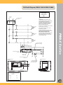
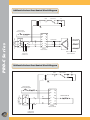
3Ø Electric Preheat Frost Control Circuit Diagram
cutout
airflow switch
SC
Line Power
208-240V/480V/3¯/60H
P RO-C S e r i e s
remote duct stat
with set point adjuster
F1
1
F2
2
3
SC
SC
SC
L1
H1
L2
H2
L3
H3
manual cutoff
fuse
Solitech
master controller
H1 H2 H3
delta- or wye-connected
electric heat coils
to main panel
on PRO-C unit
1Ø Electric Preheat Frost Control Circuit Diagram
cutout
airflow switch
remote duct stat
with set point adjuster
F1
1
F2
2
Line Power
208-240V/1¯/60Hz
3
SC
H1
L2
SC
fuse
H1
H2
to main panel
on PRO-C unit
12
L1
L3
H3
Solitech
master controller
electric heat coil
SC
Electrical Data
Select motors using the fan tables on page 6. For the unit and motors selected,
Table 5 will have the corresponding full load amps (FLA) for each motor.
Equation 2a. Formula to determine
minimum circuit ampacity (MCA) without
pre-heater.
To determine minimum circuit ampacity (MCA):
1.25 * FLA largest fan motor (Table 5)
+ FLA other fan motor (Table 5)
+ FLA wheel drive/ accessories (Table 5)
= MCA
Equation 2b. Formula to determine minimum circuit ampacity (MCA) with preheater.
= MCA
Equation 3. Formula to determine maximum
overcurrent protection (MOP).
To determine maximum overcurrent protection (MOP):
For the PRO-C-1000 without preheater: MOP=15
For the PRO-C-2400 with preheater:
+
+
+
2.25 * FLA largest fan motor (Table 5)
FLA other fan motor (Table 5)
FLA wheel drive/ accessories (Table 5)
FLA optional preheater (Table 6)
=
MOP
P RO-C S e r i e s
To determine minimum circuit ampacity (MCA):
FLA exhaust fan motor (Table 5)
+ FLA supply fan motor (Table 5)
+ FLA wheel drive/ accessories (Table 5)
+ FLA optional preheater (Table 6)
* 1.25
Using the total above, select the next smaller sized time delay fuse (LOWPEAKTM , FUSETRON or equivalent) or HACR-type circuit breaker,
minimum of 15 amps. If the fuses/breakers do not hold, consult the
National Electric Code for suitability of larger fuses/breakers.
13
Full Load Power Draw
Full Load Power Draw (Amps)
Unit
PRO-C-1000
P RO-C S e r i e s
PRO-C-2400
Motor Size
(hp)
208V/1Ø
240V/1Ø
208V/3Ø
240V/3Ø
480V/3Ø
3/4
7.6
6.9
7.6
6.9
3.5
Wheel drive/
accessories
1.1
1.1
0
0
0
1/3
4.0
3.6
1.7
1.6
0.8
3/4
7.6
6.9
3.5
3.2
1.6
1-1/2
11.0
10.0
6.6
6.0
3.0
2
13.2
12.0
7.5
6.8
3.4
3
-
-
10.6
9.6
4.8
Wheel drive/
accessories
1.6
1.6
1.6
1.6
1.6
Table 5. Electric Unit Data, Full Load Power Draw.
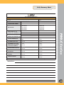
Electrical Preheat Data
An electric preheat coil is an available
option for all PRO-C units to limit the
risk of frost formation for projects that
involve high indoor humidity and/or
extreme winter design conditions.
Applications involving space
conditions that will exceed 30 percent
relative humidity when the outdoor
air temperature is below 0°F, should
extreme days, will usually prove adequate
to avoid frost formation.
Table 6 should be used to select
the appropriate size electric pre-heater
for a given application. Often it is best
to make this selection in conjunction
with your local Carrier-ERV Systems
representative to assure proper sizing.
Actual Preheater Size (kW) / Full Load Power Draw (Amps)
Model
Nominal Preheater Size (kW)
Temperature Rise
@ Full kW (°F)
208V/1Ø
240V/1Ø
208/V3Ø
240V/3Ø
480V/3Ø
PRO-C-1000
3.0
9-19
3.40 / 16.3
3.50 / 14.6
3.00 / 8.3
3.00 / 7.2
3.50 / 4.2
PRO-C-2400
7.5
10-29
7.65 / 36.8
7.5 / 31.3
7.65 / 21.2
7.5 / 18.0
7.5 / 9.0
Table 6. Electric Preheat Data.
14
be evaluated to see if preheating is
necessary. In such cases it is best to
contact your local Carrier-ERV Systems
representative for assistance.
Most applications that do not
involve space humidification will function
as desired without preheating. Even in
extremely cold climates, 10 to 15 degrees
of preheat, which is only operated on
Order Summary Sheet
PRO-C-Series Energy Recovery Module
For Carrier® Weathermaker™ & Weathermaster™ Units
JOB NAME:________________________________________________________
UNIT ID: ___________________________________
PRO-C-1000
PRO-C-2400
208V/1PH
240V/1PH
208V/3PH
240V/3PH
480V/3PH
208V/1PH
240V/1PH
208V/3PH
240V/3PH
480V/3PH
ELECTRIC PREHEAT (kW)
NO
3
NO
7.5
DISCONNECT (Non-fused)
NO
YES
NO
YES
ECONOMIZER Stop/Jog with
Rotation Sensor & Low Temp
Frost Protection (SMX-70)
NO
YES
NO
YES
START/STOP RELAY (24V AC)
NO
YES
NO
YES
THERMOSTAT FROST
PROTECTION
NO
YES
NO
YES
SEGREGATED EXHAUST
ADAPTER
NO
YES
NO
YES
PEDESTAL SUPPORT
NO
YES
NO
YES
PRO-C MODEL
CARRIER MODEL NUMBER
UNIT VOLTAGE
SUPPLY STATIC (in. wg.)
RETURN STATIC (in. wg.)
EXHAUST AIR FLOW RATE (cfm)
P RO-C S e r i e s
OUTSIDE AIR FLOW RATE (cfm)
Please Note: This order summary MUST be completed in full by the Sales Engineer.
Instructions:
15
Sample Specifications
P RO-C S e r i e s
CASING
Standard panels shall be 20 gauge galvanized steel, lined with
1/2 inch thick neoprene insulation where required. The
housing shall be supported by a formed structural base that
forms a pan to ensure weather tight construction. Lifting
holes shall be provided at the unit base. Units shall have
a weatherproof sheet metal roof. The outdoor air intake
opening shall be protected by a galvanized steel sheet metal
weather hood and include an automatic shutoff damper
with electric operator. The exhaust air discharge shall be
covered with a gravity backdraft damper and weather hood.
The exterior of the unit shall be coated with an epoxy
primer and a polyurethane enamel painting system for added
protection. Painting system shall be rated to meet a 1500
hour salt spray test.
the media. Wheel media shall be independently tested and
shown to have a flame spread of less than 25 and a smoke
generation rating of less than 50 when tested in accordance
with ASTM-E-87.
Access
FILTERS
Access to components shall be provided through a large,
tightly sealed and easily removable access panel. Access
panels shall be constructed of the same materials as the unit
casing and use standard hardware. The wheel cassette shall
be easily removable from the unit. The roof of the unit shall
also be removable for access.
The filters shall be 1 inch thick permanent aluminum
washable type mounted in the outside air hood and in the
return air plenum. The filters shall be listed by Underwriters’
Laboratories as Class 2.
Unit Configuration
The supply air inlet and exhaust air outlet must be oriented at
opposite sides of the Energy Recovery System to maximize
the distance between the two airstreams in order to minimize
the risk of short circuiting exhaust air into the supply air
intake.
The rotor cassette shall be a sheet metal framework which
limits the deflection of the rotor due to air pressure. The
cassette shall be made of galvanized steel to prevent
corrosion. The rotor cassette shall be easily removable from
the Energy Recovery Unit to facilitate rigging (if necessary)
and ease of service. The wheel cassette design shall use
pillow block bearings for long life. A non-adjustable purge
sector shall be included in the cassette.
Optional Rotation Detector
Unit shall be equipped with a rotation sensor and controller
such that should the energy recovery wheel not rotate during
a signaled run period, the controller shall send a 24 volt AC
signal suitable for operating a relay to be used as an alarm
contact. The controller shall not initiate an alarm during a
stop/jog function.
Optional Stop/Jog Economizer
FANS
Fans shall have forward curve type wheels. The blades shall
be designed for maximum efficiency and quiet operation.
Impellers shall be statically and dynamically balanced.
Fans shall be driven by direct drive motors located at the fan
inlet or by motors using belts and sheaves. Motors shall be
standard NEMA frame with open drip-proof enclosures.
V-belt drives shall be designed for a minimum 1.2 service
factor.
TOTAL ENERGY WHEEL
16
Rotor Cassette
The rotor media shall be made of aluminum which is
coated to prohibit corrosion. The rotor media shall be
coated with a non-migrating adsorbent to transfer water
vapor and to prohibit corrosion. Equal sensible and latent
recovery efficiencies shall be clearly documented through
a certification program conducted in accordance with
ASHRAE 84-91 and ARI 1060 standards. The media
shall be cleanable with low temperature steam, hot water
or light detergent, without degrading the latent recovery.
Dry particles up to 600 microns shall freely pass through
Unit shall be equipped with an outdoor air temperature
sensor and controller such that the energy recovery wheel
can be stopped during moderate temperature periods. The
controller shall perform a stop/jog function for the wheel
long enough to promote the self cleaning features of the
wheel but not long enough to induce energy recovery.
Optional Wheel Stop/Jog Frost Protection
Unit shall be equipped with an outdoor air temperature
sensor and controller such that the energy recovery wheel
can be operated in stop/jog mode during very low outdoor
air temperature periods to prevent freezing of the wheel
while still delivering outdoor air through the unit.
Optional Electric Preheat Coil
Coil shall be of the resistance coil type with elements
enclosed in a steel sheath with fins and painted with a
baked-on aluminum paint for long life in a 100% fresh air
stream. Coil shall include thermal cutout protection with
automatic primary protection and a secondary manual reset
linear thermal cutout. Coil shall have magnetic safety and
backup contactors, main disconnect, fusing, control circuit
transformer, air flow interlock switch and SCR controller.
Coil shall be UL listed and constructed in accordance with
NEC requirements. A temperature controller located in the
outdoor air section of the unit shall supply the signal to the
SCR controller.
Optional Freeze Protection Thermostat
Unit shall be equipped with an outdoor air temperature
thermostat such that the energy recovery ventilator can
be stopped during very low temperature periods. This
thermostat shall stop the both the fans and the energy
recovery wheel until the outdoor air temperature rises above
the setpoint, then the unit will restart automatically.
Units shall require a single 60 cycle power connection.
See schedule for voltage and phase requirements. The
electrical panel shall consist of individual motor contactors,
short circuit and overload protection and control power
transformer. The NEMA 3R electrical panel shall be
mounted on the unit exterior for ease of access. Unit shall
be ETL listed and labeled.
SOLE AND EXCLUSIVE WARRANTY
ERV Systems warrants to Buyer that for a period of eighteen
months from the date of shipment by ERV Systems the
goods to be delivered to Buyer will in all material respects
be free from defects in material and workmanship when
used in a proper and normal manner. Should any failure
to conform to the above appear within eighteen months
after the date of shipment by ERV Systems (the “Limited
Warranty Period”), ERV Systems agrees upon prompt
notification thereof during the Limited Warranty Period
and confirmation to ERV Systems’ satisfaction that the
goods have been stored, installed, operated and maintained
properly and in accordance with standard industry practice,
to correct the non-conformity at ERV Systems’ option either
by repairing any defective part or parts or by making available
at ERV Systems’ plant a repaired or replacement part.
P RO-C S e r i e s
ELECTRICAL
17
P RO-C S e r i e s
Notes
18
Notes
P RO-C S e r i e s
19
P RO-C S e r i e s
Notes
20
PO Box 1797
Columbia, MO 65205-1797
(573) 886-5400
(573) 886-5401 fax
www.ervsystems.com
[email protected]
AG 002 0906 1K G