1
AVM500-ES User’s Manual
1
FCC INFORMATION (U.S.A)
This device complies with Part 15 of the FCC rules.
Operation is subject to the following two conditions:
1. This device may not cause harmful
interference.
2. This device must accept any interference
received including interference that may cause
undesired operation.
1. IMPORTANT NOTICE: DO NOT MODIFY THIS UNIT!
This product, when installed as indicated in the
instructions contained in this manual, meets FCC
requirements. Modifications not expressly approved by
Yamaha may void your authority, granted by the FCC, to
use the product.
2. IMPORTANT: When connecting this product to
accessories and/or another product use only high quality
shielded cables. Cable/s supplied with this product MUST
be used. Follow all installation instructions. Failure to
follow instructions could void your FCC authorization to
use this product in the USA.
3. NOTE: This product has been tested and found to
comply with the limits for a Class B Digital device,
pursuant to Part 15 of the FCC Rules. These limits are
designed to provide reasonable protection against
harmful interference in a residential environment. This
equipment generates, uses and can radiate radio
frequency energy and, if not installed and used according
to the instructions found in the users manual, may cause
interference harmful to the operation of other radio
communications. Compliance with FCC regulations does
not guarantee that interference will not occur in all
installations. If this product is found to be the source of
interference, which can be determined by turning the unit
“OFF” and “ON”, please try to eliminate the problems by
using one of the following measures:
Relocate either this product or the device that is being
affected by the interference.
Utilize power outlets that are on different branch (circuit
breaker or fuse) circuits or install AC line filter(s).
In the case of radio or TV interference, relocate/reorient
the antenna. If the antenna lead-in is 300 ohm ribbon
lead, change the lead-in to co-axial type cable.
If these corrective measures do not produce satisfactory
results, please contact the local retailer authorized to
distribute this type of product. If you cannot locate the
appropriate retailer, please contact Yamaha Commercial
Audio Systems, Inc., Electronic Service Division, 6600
Orangethorpe Ave, Buena Park, CA90620.
The above statements apply ONLY to those products
distributed by Yamaha Commercial Audio Systems, Inc.
or its subsidiaries.
COMPLIANCE INFORMATION STATEMENT
(DECLARATION OF CONFORMITY PROCEDURE)
Responsible Party :
Address :
Telephone :
Type of Equipment :
Model Name :
Yamaha Commercial Audio Systems, Inc.
6600 Orangethorpe Ave.,
Buena Park, Calif. 90620
714-522-9011
EtherSound Network Matrix
AVM500-ES
This device complies with Part 15 of the FCC Rules.
Operation is subject to the following conditions:
1) This device may not cause harmful interference, and
2) This device must accept any interference received including
interference that may cause undesired operation.
See user manual instructions if interference to radio reception is
suspected.
AVM500-ES User’s Manual
2
WARNING
Always follow the basic precautions listed below to avoid the possibility of serious injury or even death from
electrical shock, short-circuiting, damages, fire or other hazards. These precautions include, but are not limited
to, the following:
PRECAUTIONS
• Do not modify, open or disassemble the Product. The
guarantee shall be null and void in that case.
• NO: "Apparatet må tilkoples jordet stikkontakt"
• Do not apply excessive pressure on connectors or
any other part of the board. Do not touch the metallic
sharp parts (pins) of the product.
• SE: "Apparaten skall anslutas till jordat uttag"
• This product is electrostatic sensitive; make sure you
check this before touching or using it.
• The disconnect devices of the unit are the appliance
inlet of the auxiliary power supply and the appliance
inlet on the rear side of the unit. These must be easily
reachable.
• Conformity of this product is subject to proper
electrical wiring, regarding CEI364 (NFC15-100).
Installation must be equipped with differential
protection.
• To prevent electric shock, do not remove the cover.
No user-serviceable parts inside. This unit contains
hazardous voltages and should only be opened by a
trained and qualified technician. Both power supply
sources must be disconnected before servicing.
• Each connection must be Safety Extra Low Voltage
kind (SELV), and must stay inside buildings.
• FI: "Laite on liitettävä suojamaadoituskoskettimilla
varustettuun pistorasiaan"
AVM500-ES User’s Manual
• This product is designed to be rack-mounted. Be sure
to observe following installation rules of this kind of
equipment:
Elevated Operating Ambient - If installed in a
closed or multi-unit rack assembly, the operating
ambient temperature of the rack environment may be
greater than room ambient. Therefore, consideration
should be given to installing the equipment in an
environment compatible with the maximum ambient
temperature (Tma) specified by the manufacturer.
Reduced Air Flow - Installation of the equipment in a
rack should be such that the amount of air flow
required for safe operation of the equipment is not
compromised.
Mechanical Loading - Mounting of the equipment in
the rack should be such that a hazardous condition is
not achieved due to uneven mechanical loading.
Circuit Overloading - Consideration should be given
to the connection of the equipment to the supply
circuit and the effect that overloading of the circuits
might have on over current protection and supply
wiring. Appropriate consideration of equipment
nameplate ratings should be used when addressing
this concern.
Reliable Earthing - Reliable earthing of rackmounted equipment should be maintained. Particular
attention should be given to supply connections other
than direct connections to the branch circuit (e.g. use
of power strips).
3
ELECTRICAL AND ELECTRONIC INTERFERENCES RISKS
This Product uses high frequency digital circuits that
might interfere with electrical or electronic devices placed
in your working environment. Please make sure this kind
of device (television, radio device, cell phones) is
removed in order to ensure a proper functioning of each
device.
• Always use shielded cables and connectors (serial
port, word clock and EtherSound ports). In the other
case, AuviTran will not guarantee the proper behavior
of the product.
• Serial port cable must be length < 1m to ensure
proper EMC and interferences behavior.
• Word clock cable must be length < 1m to ensure
proper EMC and interferences behavior.
LIMITATION OF LIABILITY
In no case and in no way, the provider of this Product
(AuviTran, the distributor or reseller, or any other party
acting as provider) shall be liable and sued to court for
damage, either direct or indirect, caused by and to the
user of the board and which would result from an
improper installation or misuse of the Product. “Misuse”
and “improper installation” mean installation and use not
corresponding to the instructions of this manual.
AVM500-ES User’s Manual
Please note that graphics given in this manual (drawings
and schemes) are only examples and shall not be taken
for a real vision of your own equipment configuration.
AuviTran is constantly working on the improvement of the
products. For that purpose, the products functionalities
are bound to change and be upgraded without notice.
Please read carefully the User’s manual as the new
functionalities will be described therein.
AuviTran 2010
4
TRADEMARKS
All trademarks listed in this manual are the exclusive property of their respective owners. They are respected “as is” by
AuviTran. Any use of these trademarks must receive prior approval of their respective owners. For any question, please
contact the trademark’s owner directly.
COPYRIGHT
The information in this manual is protected by copyright. Therefore, reproduction, distribution of whole or part of this manual
is strictly forbidden without the prior written agreement of AuviTran.
AUVITRAN WEBSITE / MORE INFORMATION
Please visit our website for any question of further inquiry concerning our product range. Updates will also be posted when
available.
http://www.auvitran.com
PACKAGE CONTAINS
•
•
•
1 AVM500-ES
1 Power Cord
1 Safety Instructions Manual
L Cord-set with proper plug configuration must be used, depending on country in which the product is used
AVM500-ES User’s Manual v2.1
AuviTran 2010
5
TABLE OF CONTENTS
1
WELCOME!............................................................................................................... 8
2
WHAT’S NEW?......................................................................................................... 8
3
TECHNICAL SPECIFICATIONS............................................................................... 9
4
REAR PANEL DESCRIPTION................................................................................ 10
5
TYPICAL ARCHITECTURE USING AVM500-ES .................................................. 10
6
POWERING AN AVM500-ES FOR THE FIRST TIME............................................ 11
6.1
Definition of Mono Network Mode ..................................................................... 11
6.2
How to build a simple Star Architecture ............................................................. 12
6.2.1
Example #1 - NAI48-ES {ch1-16} to AVY16-ES100 {ch1-16}................................................................................... 15
6.2.2
Example #2 – AVY16-ES100 {ch13-16} to NXAmp {ch1-4} ..................................................................................... 17
6.3
Why using Star Architecture instead of basic Dasy-Chain? .................................... 19
6.4
Limitations of the Mono Network Mode .............................................................. 21
6.4.1
Port {Aout} inactive ................................................................................................................................................... 21
6.4.2
Remote control through 3rd Port – ES100/ESV2...................................................................................................... 21
7
SPLITTING NETWORKS FOR EXTENDED CAPACITIES.................................... 23
7.1
PM Multi Networks Mode – Hardware configuration .............................................. 23
7.1.1
Port {Aout} active....................................................................................................................................................... 24
7.1.2
Remote control through 3rd Port – ES100/ESV2...................................................................................................... 24
7.2
Generic Multi Networks Mode – Software configuration......................................... 25
7.2.1
Definition of the generic Multi Networks Mode....................................................................................................... 25
7.2.2
Example of dissociated network .............................................................................................................................. 27
7.2.3
Building Ring Architecture ....................................................................................................................................... 29
7.3
Advanced Users: Multi Network Mode – Input configuration ................................... 30
8
AVM500-ES IN ES-MONITOR SOFTWARE .......................................................... 32
8.1
Software Installation...................................................................................... 32
8.2
Getting Started with AVM500-ES and ES-Monitor Software..................................... 32
8.3
AVM500-ES Properties Page in ES-Monitor......................................................... 33
8.4
AVM500-ES Matrix Page in ES-Monitor .............................................................. 34
8.5
AVM500-ES Control Page in ES-Monitor............................................................. 37
8.5.1
Status box................................................................................................................................................................... 37
8.5.2
Port Configuration box.............................................................................................................................................. 38
8.5.3
Port A – EtherSound Channel Direction box........................................................................................................... 38
8.5.4
Clock Control box ...................................................................................................................................................... 39
8.5.5
Tunneling Setup box ................................................................................................................................................. 39
8.5.6
Serial Port Configuration box ................................................................................................................................... 39
9
TUNNELING – GENERAL INFORMATION............................................................ 40
AVM500-ES User’s Manual v2.1
AuviTran 2010
6
9.1
Ex. 1: Communication between AVY16-ES100 and Serial Port................................. 40
9.1.1
AVY16-ES100 is plugged on port B.......................................................................................................................... 40
9.1.2
And if AVY16-ES100 is plugged on another port?.................................................................................................. 41
9.2
Ex. 2: Multiple tunneling – Port dissociation ....................................................... 42
10
SERIAL PORT INTERPRETER .............................................................................. 44
10.1 Enable Interpreter mode ................................................................................. 44
10.2 System architecture and conventions................................................................ 45
10.3 Programming interface................................................................................... 45
10.3.1 Get serial protocol version ....................................................................................................................................... 45
10.3.2 Set output patch......................................................................................................................................................... 46
10.3.3 Mute output ................................................................................................................................................................ 46
10.3.4 UnMute output............................................................................................................................................................ 46
10.3.5 Get output patch ........................................................................................................................................................ 47
10.3.6 Patch example with Tera Term ®.............................................................................................................................. 48
11
ASIO CONFIGURATION ........................................................................................ 49
11.1 Enable ASIO mode ........................................................................................ 49
11.2 Disable ASIO mode ....................................................................................... 50
11.3 Play and Record with an ASIO port ................................................................... 50
12
AUXILIARY POWER SUPPLY ............................................................................... 52
13
FIRMWARE UPDATE ............................................................................................. 52
AVM500-ES User’s Manual v2.1
AuviTran 2010
7
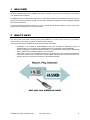
1
WELCOME!
Thank you for purchasing AuviTran’s AVM500-ES. We hope you will enjoy using it. This product will help you in expanding
your current EtherSound networks.
As AVM500-ES acts as an EtherSound matrix router, you will be able to handle up to 320 EtherSound channels linked to 5
physical ports, build ring redundancy topology, and many others architectures. AVM500-ES is able to aggregate separated
ES V2 and ES100 networks.
You will find herewith the necessary instructions to use your product. Please read them carefully as misuse of this device
might cause serious damage to you and your environment.
2
WHAT’S NEW?
This version of the manual refers to the last firmware of the AVM500-ES, i.e. version 0x110C / 0x118C. You are invited to
check the version of your device, and perform a firmware update if necessary.
Thanks to this new firmware, AVM500-ES has the following extended functionality:
- AVM500-ES is now available as AVM500-ES/3ports, with all the advantages of AVM500-ES, limited to 3
EtherSound ports, at a very attractive cost. AVM500-ES/3ports stays upgradable to regular AVM500-ES.
- Serial Port embedded a command interpreter that allows you to patch the whole matrix through a simple RS232
protocol. Please refer to dedicated paragraph for more information.
- Device ports C, D and E can be swapped from EtherSound to ASIO protocol. ASIO computer-based application
will be able to play/record up to 64 channels on each port. Matrix patch allows choosing which channel is to be
played or recorded. You will find more information in the dedicated paragraph.
AVM500-ES User’s Manual v2.1
AuviTran 2010
8
3
TECHNICAL SPECIFICATIONS
General
Size
Power Consumption
Main Power Supply
DC supply (Auxiliary)
Auxiliary Power Supply
Storage: Temp/Humidity
Operating: Temp/Humidity
Front Panel
Rear Panel
483 x 253 x 44mm (19’ rack / 1U Height)
<50 Watts
100-240VAC 50/60Hz 1.5A Max
5Vdc 5A max – 12Vdc 2A max
100-240V~ 47-63Hz 1.35A / +5Vdc 5A ; +12Vdc 2A
- 5°C to 70°C / Max 95% (non-condensing)
5°C to 40°C / 5% to 90% (non-condensing)
Networks and links Rx and Tx Activities; Active synch running ; Power Main, Aux and On Display
1 IEC Power inlet; 7 Neutrik EtherCon RJ45; 1x6 poles Euroblock Connector for Aux power supply; 1 BNC for word
clock synch in; 1 DB9 connector for Serial Port
AVM500-ES Features
EtherSound Network Segment
EtherSound IN Port
EtherSound OUT Port
ES-100 to ES-100 Latency
Digital Audio Channels
Matrix / Patch size
Remote control
Other I/O
Clock Synchronisation mode
5 EtherSound Network Segments interconnections : A (In, Out), B, C, D, E
1 EtherSound IN Port: AIN
5 EtherSound OUT Ports: AOUT, B, C, D and E
6 samples (125µs at 48 kHz)
320 (5 x 64) Input Audio channels and 320 (5 x 64) Output Audio channels
320x320 full cross matrix with remote control patch via EtherSound
Any individual output audio channel can be muted or patched to any of the 320 available Input audio channels
Via EtherSound of from Ethernet PC remote link
RS232 serial port
48 kHz local clock (when Primary Master) or EtherSound Network (When not PM)
Word clock In used for synchronisation
Temp / Fan monitoring
Temp Monitoring
PSU Monitoring
2 Fan Control modes
Network Monitoring of Temperature inside the Box
Network Monitoring of PSU Failure for Main and Aux power supply
Automatically Controlled by internal Temperature
Off
Development and Integration Environment
OS Supported
ES-Monitor
Remote Network Management
Windows XP
ES-Monitor enables to remotely set, control and monitor an EtherSound network and provides enhanced property
pages to manage the AVM500-ES specific parameters.
Links status, Power supply status (Main, Aux), Temperature monitoring , Fan remote control and PSU Aux/Main
remote control
AVM500-ES User’s Manual v2.1
AuviTran 2010
9
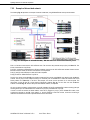
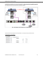
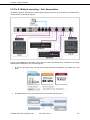
Rear Panel Description – Typical architecture
4
5
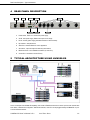
REAR PANEL DESCRIPTION
2-
Power switch : switch on or off the main power supply
3-
AC IN : main power supply. Refer to tech specs for AC range
4-
DC IN : auxiliary power supply (described at the end of this document)
5-
Dip switches : setup the device
6-
Serial Port : standard RS232 for custom application
7-
Word Clock : Input and Output for external synchronization
8-
EtherSound Ports : link to EtherSound network (or control PC)
9-
Control Port : connection to control PC only
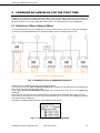
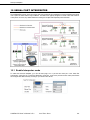
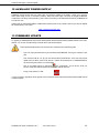
TYPICAL ARCHITECTURE USING AVM500-ES
This is an example of the AVM500-ES capability: each cluster of EtherSound devices can share up to 64 audio channels with
each others, in bidirectional configuration. With ES100 networks, control PC can be plugged directly to AVM500-ES “3rd port”
to control the whole network.
AVM500-ES User’s Manual v2.1
AuviTran 2010
10
Powering an AVM500-ES for the first time
6
POWERING AN AVM500-ES FOR THE FIRST TIME
AVM500-ES is a dedicated and versatile EtherSound network router and matrix. Many configurations and parameters are
available to best fit each kind of architecture you want to build. When powering an AVM500-ES for the first time, it will boot in
the factory configuration. This mode is called “Mono network mode”. This is the simplest way to use an AVM500-ES.
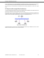
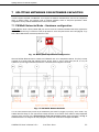
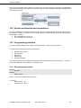
6.1 Definition of Mono Network Mode
To be more efficient when using your AVM500-ES, you need to understand how it is build. If you have a look to the Fig. 1,
you will see how the AVM500-ES behave when in the Mono Network mode, from EtherSound point of view.
Fig. 1: Simplified view of AVM500-ES behavior
AVM500-ES acts as 5 EtherSound devices, with smart interconnections
From a network point of view, {Ain} is an EtherSound input port. The output port of the related device is connected to the 4
others device’s input ports, through a regular switch.
Doing so, {B, C, D, E} ports are EtherSound output ports. From a hierarchic point of view, {B, C, D, E} are behind {Ain}
(see Fig. 2).
All 64in channels + 64out channels of each device are always connected to the 320x320 digital audio matrix, at any time.
Audio clock for synchronization is coming from {Ain} port and distributed to {B, C, D, E} ports. This is always true, whatever
the configuration of the AVM500-ES.
Audio patch of the 320x320 digital audio matrix is only available through {Ain} port.
Fig. 2: Tree view in Mono Network Mode
AVM500-ES User’s Manual v2.1
AuviTran 2010
11
Powering an AVM500-ES for the first time
To sum-up theses points, we can compare AVM500-ES to an EtherSound device with one input port and four output ports.
These four ports are always synchronized to the input port. Each port can share its audio channels with each other.
This mode allows you to build bidirectional star architecture that was absolutely impossible to do before, with a regular
switch.
6.2 How to build a simple Star Architecture
You will find herewith all the procedure to build your first star architecture with an AVM500-ES in Mono Network Mode. Audio
patch will also be detailed here to help you handle the device step by step.
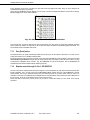
Fig. 3 illustrates what we call a star architecture. In few words, a star architecture has a “node” that acts as a splitter. This is
a point where a network is divided in multiple branches. This vision is true for the downstream. For the upstream, this is the
opposite. The node “concentrates” multiple branches in a single one. The AVM500-ES is this node.
Fig. 3: Star architecture
In the following example, you will learn how to build a real EtherSound network using an AVM500-ES, and how to use the
Netpatch to route audio channels. Let’s have a look to the schematic:
AVM500-ES User’s Manual v2.1
AuviTran 2010
12
Powering an AVM500-ES for the first time
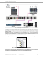
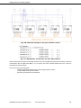
Fig. 4: Example of architecture
In this network, the AVY16-ES100 in the LS9 mixing console is the Primary Master (PM). Indeed, there is no EtherSound
network plugged on its In port, but only the control PC. The Out port of the AVY16-ES100 is connected to port {Ain} of the
AVM500-ES. Ports {B, C, D}, that are Outputs ports, are connected respectively to port In of DME4io, NAI48-ES and NXAmp
4x4. Port {E} is unused.
Remember that in this example, the AVY16-ES100 is PM, so it generates the audio clock. This clock is transmitted to the
AVM500-ES port {Ain} through EtherSound. As described in the previous paragraph, AVM500-ES propagates the clock from
{Ain} to {B, C, D, E}, so the three third-party devices are properly feed with clock.
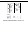
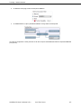
When running AuviTran ES-Monitor software on the control PC, the Tree View of this network will be the following:
Fig. 5: Hierarchy view of example architecture
The AVY16-ES100 is obviously the Primary Master, followed by port {Ain} of the AVM500-ES. Ports {B, C, D, E} are on the
same hierarchy level, as expected. And behind each port, we can find our three EtherSound devices.
AVM500-ES User’s Manual v2.1
AuviTran 2010
13
Powering an AVM500-ES for the first time
L
The following description of Netpatch is based on version 3.9.3 of ES-Monitor software,
which is the official released version at the time where this manual is written.
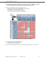
Let’s have a look to the Netpatch now. We can see four different colours in it:
- White, means you can make a direct connection between source and destination.
- Gray, means there is no way to make a direct connection.
- Pink, means this is the matrix internal patch of an AVM500-ES.
- Yellow, means that there is a possible path through an AVM500-ES.
Fig. 6: NetPatch view of example architecture
In this example, you will learn how to make the following patch:
(1) NAI48-ES {ch1-16} to AVY16-ES100 {ch1-16}
(2) AVY16-ES100 {ch13-16} to NXAmp {ch1-4}
Since version 3.9.3 of ES-Monitor software, such a path is now extremely easy using net patch. It is a “one click” process.
AVM500-ES User’s Manual v2.1
AuviTran 2010
14
Powering an AVM500-ES for the first time
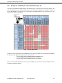
6.2.1 Example #1 - NAI48-ES {ch1-16} to AVY16-ES100 {ch1-16}
If you want to route NAI48-ES channels directly to AVY16-ES100 inputs, you will see that you are facing a yellow cell. This
means that Netpatch found a connection between theses two devices through an AVM500-ES. As patch grid is collapsed 16
by 16 in this example, all you have to do is to click the yellow cell between NAI48 {ch1-16} and AVY16 {ch1-16}. The
software will do everything automatically!
Fig. 7: First step patch
The patch you’ve just made in yellow cell is represented by a star. This is the symbolic view for a patch through an AVM500ES. At the same time, Netpatch added the real path of audio channels:
- One cross (direct connection) between NAI48 and AVM500-ES Port C.
- One circle (AVM500 internal patch) between Port C and Port A.
- One cross (direct connection) between Port A and AVY16-ES100.
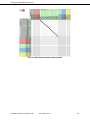
Now, if you select AVM500-ES port {Ain}, and then you go to the “Matrix” tab, you will notice that internal digital audio matrix
was effectively patched as expected.
AVM500-ES User’s Manual v2.1
AuviTran 2010
15
Powering an AVM500-ES for the first time
Fig. 8: First step automatic Matrix patch
AVM500-ES User’s Manual v2.1
AuviTran 2010
16
Powering an AVM500-ES for the first time
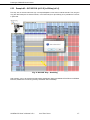
6.2.2 Example #2 – AVY16-ES100 {ch13-16} to NXAmp {ch1-4}
Final step, and one more time the same logic. Just expand Netpatch to have access to desired channels. Then, drag and
drop (with “Shift” button) the four desired channels, i.e. AVY16-ES100 {ch13-16} to NXAmp {ch1-4} available one more time
in yellow cells.
Fig. 9: Second step - Patching
Apply selection, and you will see the whole path patched automatically. Notice patch between AVY16-ES100 and AVM500ES Port A, between Port A and Port D (pink cells), and between Port D and NXAmp.
AVM500-ES User’s Manual v2.1
AuviTran 2010
17
Powering an AVM500-ES for the first time
Fig. 10: Second step - Patched
More information, tips and tricks regarding Netpatch is available in ES-Monitor User’s Manual. Please directly refer to it learn
how to handle it perfectly.
AVM500-ES User’s Manual v2.1
AuviTran 2010
18
Powering an AVM500-ES for the first time
6.3 Why using Star Architecture instead of basic Dasy-Chain?
For a simple network as described previously, AVM500-ES seems to be largely under-used. Indeed, regarding the few
channels used, we could have built a standard Daisy-Chain network (Fig. 11).
Fig. 11: Equivalent Daisy-Chain architecture
If this kind of architecture would have perfectly worked, it has also a big drawback:
- if the cable between NAI48-ES and DME4io fails,
- if the NAI48-ES fails or is switched-off,
- if the DME4io fails or is switched-off,
in all of theses cases, audio channels will never reach the NXAmp, and diffusion will be lost.
Big advantage of the star architecture is to bypass this issue. Indeed, if a branch of the star fails, the rest of the network
continue to work. For example, if DME4io fails, you will only loose its channels, but NAI48-ES channels and AVY16-ES100
channels can still be played on the NXAmp. Of course this is the same idea for all other branches of the network.
AVM500-ES User’s Manual v2.1
AuviTran 2010
19
Powering an AVM500-ES for the first time
A classic example is a recording studio, with multiple recording rooms. If each room is a branch of the star, then you don’t
have to bother of the state of the other rooms (devices on or off) when you want to record one.
Fig. 12: Example of Star architecture
AVM500-ES User’s Manual v2.1
AuviTran 2010
20
Powering an AVM500-ES for the first time
6.4 Limitations of the Mono Network Mode
Mono Network Mode is the factory default mode, and the simplest way to use AVM500-ES. Nevertheless this mode as also
few limitations that do not allows the user to take the best of the possibilities of the device.
6.4.1 Port {Aout} inactive
Looking back to Fig. 1, we can see that the output port of port A is already used to communicate with the four other devices
via the internal switch. Doing so, the back-panel port {Aout} is unwired in this mode. Plugging an EtherSound compatible
device on this port has no effect.
6.4.2 Remote control through 3rd Port – ES100/ESV2
Back-panel port {3rd} is the computer local access point of the device, regarding to ES100 technology. Please refer to the
proper EtherSound manual if you are not used with ES100 standard and especially 3rd port access. This port accepts only
a computer for remote control. No EtherSound compatible device should be plugged on it (Fig. 15).
Connecting a computer on this port allows you to remote control the whole network directly from this point. Plugging the
control PC on the Primary Master input port is no more mandatory.
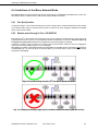
Nevertheless, the limitation of Mono Network Mode is that all EtherSound compatible devices of the network must be ES100
compatible (Fig. 13). If an old ES-V2 device is inside the network, you will not be able to control and monitor the network
through the 3rd port (Fig. 14).
Fig. 13: Good wiring of port {3rd} in Mono Network Mode
Fig. 14: Improper wiring of port {3rd} in Mono Network Mode (ES-V2 inside)
AVM500-ES User’s Manual v2.1
AuviTran 2010
21
Powering an AVM500-ES for the first time
Fig. 15: Improper wiring of port {3rd} (EtherSound stream on the port)
AVM500-ES User’s Manual v2.1
AuviTran 2010
22
Splitting networks for extended capacities
7
SPLITTING NETWORKS FOR EXTENDED CAPACITIES
In order to expand capacities of AVM500-ES, and to bypass the limitations described above, the user can configure the
device in different modes. One particular mode is hardware selectable, thanks to rear-panel dip-switches. Others
configurations are fully software selectable thanks to ES-monitor software.
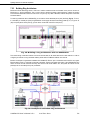
7.1 PM Multi Networks Mode – Hardware configuration
If and only if the device is Primary Master (PM), the user has access to a hardware selectable mode that re-organizes the
AVM500-ES internal wiring. To access this mode, the dip-switch #1 on the rear panel must be set to “ON” (Fig. 16). To go
back to Mono Network Mode, reset the dip-switch #1 to “OFF”.
Fig. 16: Rear-panel dip-switch configuration
When the PM Multi Networks Mode is activated, the AVM500-ES acts as five independent networks. Port {Ain} is directly
connected to an internal switch that addresses the five devices. Doing so, the five output ports {Aout, B, C, D, E} are
available for the user. Fig. 17 illustrates the behaviour of the device when configured in this mode.
Fig. 17: PM Multi Networks Mode
You can notice that each input port will only be addressed by the control PC plugged on port {Ain}, as this mode is only
available when PM. Doing so, each port becomes virtually the PM of its own network. Each network is totally independent
regarding control commands, but is still dependant on audio and clock point of view. Indeed, the bottom of the Fig. 17
indicates that there is no change for the clock propagation, and the audio connection to the Digital Audio Matrix.
AVM500-ES User’s Manual v2.1
AuviTran 2010
23
Splitting networks for extended capacities
Port A generates its own clock, and sends it to other ports and to the digital audio matrix. Doing so, all five networks are
automatically and properly synchronized.
When looking at ES-Monitor software (Fig. 18), you can clearly view the five independent networks. It looks like five Primary
Masters plugged on the same control computer.
Fig. 18: PM Multi Networks Mode in ES-Monitor
The fact that ports are virtually PM (because still synchronized to port {Ain}) allows to bypass few limitations described
before, without any limitation on audio side, as all five ports are always connected to the 320x320 Digital Audio Matrix. You
will find below all new possibilities of this mode.
7.1.1 Port {Aout} active
As explained above, this mode automatically enables the port {Aout} on the back-panel of the device. You have now five
output ports instead of four in the Mono Network Mode.
Be careful using this mode, and always think that it only works when AVM500-ES is Primary Master. That means that you
cannot build a ring architecture using the pair {Ain/Aout}, because {Ain} only accepts a control PC in this mode. If you plug
an EtherSound compatible device to build a ring, the AVM500-ES will not be PM anymore, and the AVM500-ES will
automatically switch to Mono Network Mode, disabling port {Aout}.
7.1.2 Remote control through 3rd Port – ES100/ESV2
We saw in the previous chapter that remote control using the 3rd port was effective only if all devices inside the network were
ES100 compatible. This is not true anymore in PM Multi Network Mode. Indeed, each port of the AVM500-ES is virtually
Primary Master, and port {3rd} addresses directly each port individually thanks to an internal switch. Doing so, there is no
restriction on the version of the EtherSound compatibles devices inside the network. ES-V2 will work as well as ES100. Even
ES-V1 will work, but we do not recommend using this kind of devices today.
Please note that you are free to choose port {3rd} or port {Ain} to connect the control PC in this mode. This is exactly
equivalent.
AVM500-ES User’s Manual v2.1
AuviTran 2010
24
Splitting networks for extended capacities
7.2 Generic Multi Networks Mode – Software configuration
We saw in chapter 7.1 an interesting way to expand capacities of AVM500-ES. The limitation of this mode is that AVM500ES must be Primary Master. This chapter will explain how to configure your AVM500-ES thanks to ES-Monitor software, to
do almost same things than before, but without the Primary Master limitation.
7.2.1 Definition of the generic Multi Networks Mode
In chapter 6.1, Fig. 1 illustrates a very simplified view of the AVM500-ES behavior. It is in fact a little bit more complicated.
Let’s look at Fig. 19 below.
Fig. 19: Real view of AVM500-ES behavior
Compared to Fig. 1, some switches have appeared. These are controlled via ES-Monitor software, in AVM500-ES Control
Page (Fig. 21). When activating a switch, the related port is dissociated. No more EtherSound stream can reach it, and so
becomes a virtual Primary Master. When all {B, C, D, E} ports are dissociated, you can notice that the internal switch
becomes useless. That’s why the switch named [CAout] automatically switches on, and connects the port {Aout} on the rear
panel.
The goal of the dissociation is the same than before, i.e. merge ES100 and ES-V2 networks and build multiple tunneling
communications. When port {Aout} is activated, you will also be able to build ring architecture. This will be described in the
next paragraph.
As no EtherSound stream can reach the ports when they are dissociated, you will need to plug the control PC to the port {3rd}
if you want to remote control your network.
AVM500-ES User’s Manual v2.1
AuviTran 2010
25
Splitting networks for extended capacities
Fig. 20: Internal wiring for 3rd port remote control
Fig. 21: ES-Monitor control box for port dissociation
Please note that port dissociation has absolutely no effect on the clock propagation through the devices, neither on the audio
communication with the Digital Audio Matrix. You can always route audio channels between ports even if they are
dissociated from the main network.
Let’s just sum-up why dissociating ports:
- use ES-V2 equipments inside the network, while using port {3rd} to control it
- manage multiple tunneling communications
- activate port {Aout} to build a ring architecture
AVM500-ES User’s Manual v2.1
AuviTran 2010
26
Splitting networks for extended capacities
7.2.2 Example of dissociated network
The following Fig. 22 represents an example of network architecture, using AVM500-ES with some ports dissociated.
Fig. 22: Example of mixed ES100 / ES-V2 network with dissociated ports
FOH is a Yamaha console with two AVY16-ES100 cards. The cards are daisy-chained with port {Ain} of AVM500-ES. This
branch of the network is fully ES100.
Port {B} is connected to a NAI48-ES that is ES100 compatible, and then to two AVY16-ES inside another Yamaha console.
Because of the AVY16-ES, this branch of the network is not fully ES100.
Ports {C} and {D} receive NXAmp 4x4, that are ES100 compatible.
Port {E} receives an AVB32-ES that is only ES-V2.
The goal is to remote control AD8HRs from network 3 with the FOH console, and AD8HRs from network 2 with the Monitor
console. The only way to have multiple tunneling is to dissociate ports of AVM500-ES to create sub-networks with virtual
Primary Master. As AVM500-ES is not PM in this example, we cannot use the dip-switch #1 on the rear-panel. The
dissociation of ports {B} and {E} is done thanks to ES-Monitor software (Fig. 24). List and Tree view from ES-Monitor
software is available Fig. 23. We can clearly see three different networks, as expected.
We can now build a tunneling communication on port {B}, between AVY16-ES and NAI48-ES. Another tunneling (inter-port
tunneling this time) is also build between AVY16-ES100 on port {Ain} and AVB32-ES on port {E}.
In order to control and monitor the entire network, control PC is plugged on port {3rd} of the AVM500-ES. Indeed, if this
computer was plugged on the PM of the network, i.e. the AVY16-ES100 in the FOH console, control and monitoring of
network #2 and #3 would have been impossible because of the dissociation.
AVM500-ES User’s Manual v2.1
AuviTran 2010
27
Splitting networks for extended capacities
Fig. 23: List and Tree view of the networks
Fig. 24: ES-Monitor configuration for the dissociated ports
All necessary instruction regarding the tunneling configuration will be detailed in the appropriate paragraph of this manual.
AVM500-ES User’s Manual v2.1
AuviTran 2010
28
Splitting networks for extended capacities
7.2.3 Building Ring Architecture
EtherSound ES100 technology allows a new kind of network architecture that was forbidden in the previous versions of
EtherSound, i.e. the ring architecture. This is a way to secure a network by adding a cable redundancy. Indeed, this solution
ensure that the network will continue to work even if one (and only one) cable is defective, whatever the position of the cable
inside the network.
To build ring architecture with an AVM500-ES, you will need to use the dedicated pair of ports {Ain/Aout} (Fig. 25). To do so,
it is mandatory to activate port {Aout} using ES-Monitor control page, that means dissociate all other {B, C, D, E} ports. As
{Ain} and {Aout} will be used by the ring, you will need to connect the control PC to the port {3rd}.
Fig. 25: Building a ring architecture with an AVM500-ES
This solution brings a redundant network of 64 audio channels that can be shared with the four other networks. In order to
configure your network as a ring redundant network, please refer to ES-Monitor software user’s manual.
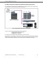
Below is an example of ring architecture between four AVM500-ES. Each 3rd port is connected to the control PC via a regular
Ethernet switch. Doing so, all devices are remotely controllable. Thanks to the digital audio matrix of each AVM500-ES, each
device can share its audio channels with every other device in the whole network. Also, the system will continue to work
perfectly even if a red cable (but only one) is defective.
Fig. 26: Example of redundant ring architecture
AVM500-ES User’s Manual v2.1
AuviTran 2010
29
Splitting networks for extended capacities
7.3 Advanced Users: Multi Network Mode – Input configuration
This mode requires good knowledge of AVM500-ES capabilities and EtherSound networks. It has been
designed to take the maximum of AVM500-ES possibilities. This mode is for very specific architectures, and
majority of AVM500-ES users can ignore it.
Aim of this mode is to choose if ports {B, C, D, E}, when dissociated, will individually act as EtherSound input ports or
EtherSound output ports.
Without any special configuration, ports {B, C, D, E} are EtherSound output ports regarding previous paragraphs. When
dissociated, the input port becomes useless (see Fig. 19). In this case, an internal switch allows the user to choose if the
physical port must be tied to the EtherSound input port, or to the EtherSound output port.
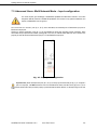
Fig. 27: Input port configuration
Important note: please remember that ports {B, C, D, E} are always synchronized with port {A}. If you configure a
port as an input port, it will NOT receive the clock from the EtherSound stream, but still from the {A} port. It is you to
ensure that all devices tied to this port will be properly synchronized with the others networks, for example using a word clock
cable.
AVM500-ES User’s Manual v2.1
AuviTran 2010
30
Splitting networks for extended capacities
Some EtherSound compatible devices need to be Primary Master in order to have remote control capabilities (for example
SY80 control surface with DIO core). The input port configuration on AVM500-ES allows having multiple Primary Masters, to
have multiple remote controls, but with word clock synchronization restriction.
Fig. 28: Example with Input Port configuration
L Note the Word Clock link between the two Primary Masters, to ensure proper clocking of the whole network.
Configuration in ES-Monitor:
AVM500-ES User’s Manual v2.1
AuviTran 2010
31
AVM500-ES in ES-Monitor software
8
AVM500-ES IN ES-MONITOR SOFTWARE
8.1 Software Installation
Please visit our website to download the latest version of our EtherSound Monitor Software called ES-Monitor
(http://www.auvitran.com/www/index.php?page=downloads ) and save the file on your hard disk. ES-Monitor requires
Windows 2000, XP or Vista to function.
You are now ready for installation. Refer to the ES-Monitor documentation for installation.
When ES-Monitor is installed on your PC, you can run ES-Monitor and manage any AVM500-ES devices connected to an
EtherSound network. Refer to ES-Monitor documentation for generic EtherSound device management such as Enumeration
of EtherSound devices.
8.2 Getting Started with AVM500-ES and ES-Monitor Software
The computer on which the EtherSound Monitor is installed should now be connected to the primary master of the
EtherSound network. The primary master must be the first EtherSound-based device of the network.
After running the ES-Monitor, Select an AVM500-ES device on the device list or tree list.
L
The following description is based on version 3.9.3 of ES-Monitor software, which is the
official released version at the time where this manual is written.
AVM500-ES User’s Manual v2.1
AuviTran 2010
32
AVM500-ES in ES-Monitor software
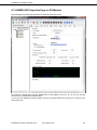
8.3 AVM500-ES Properties Page in ES-Monitor
When selecting the properties page, ES-Monitor will display the following information:
The control PC is plugged to the port {Ain}. AVM500-ES is so Primary Master. All ports {A, B, C, D, E} are on the same
hierarchic level, as it will be with an Ethernet switch.
You can find in the “EtherSound module properties” box the port currently selected, that can helps you to create your own
device alias (name).
AVM500-ES User’s Manual v2.1
AuviTran 2010
33
AVM500-ES in ES-Monitor software
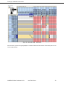
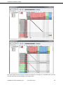
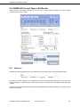
8.4 AVM500-ES Matrix Page in ES-Monitor
If the Matrix page is selected, ES-Monitor will display following information:
This is the patch matrix of the 320 EtherSound channels. Each port can handle 64 channels. This is the synthetic view of the
matrix, so channels are grouped 16 by 16. You can click on each row or column to expand it, to handle channels one by one.
icon in the “receivers” row and “sources” column to expand / collapse in one time the whole
You can also click on
matrix.
Click on the
icon to remove the whole patch you may have previously entered.
Click on the
icon to resize the matrix by a factor 2. This is really useful if your computer screen is not large enough.
You will find below two screenshots of the matrix illustrating the possibilities:
AVM500-ES User’s Manual v2.1
AuviTran 2010
34
AVM500-ES in ES-Monitor software
Each row will display the name of the port / channel that is patched to it. This helps you to remember quickly your patch,
even if the whole matrix cannot be displayed on the computer screen.
AVM500-ES User’s Manual v2.1
AuviTran 2010
35
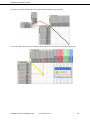
AVM500-ES in ES-Monitor software
If you click on a couple of collapsed row / column, this will create a diagonal on the 16 channels.
You can also use the “Shift” key of your keyboard to draw a diagonal or a column with the mouse, like a drag and drop.
AVM500-ES User’s Manual v2.1
AuviTran 2010
36
AVM500-ES in ES-Monitor software
8.5 AVM500-ES Control Page in ES-Monitor
Control pages are quite different depending on the port that is currently selected. ES-Monitor will display following
information when port {A} is selected:
8.5.1 Status box
The Status box shows temperature in the box, fan speed and its turn-off switch, and the front panel brightness setting.
Fan speed is automatic, depending on box temperature. Thresholds were optimized regarding fan noise and maximum
working temperature. For noise-critical environment, fan can be turn-off. This status box is only available on the control page
of port A.
L Please note that if internal temperature becomes too high, AVM500-ES will override the “Stop Fan” command to ensure
proper cooling of the box.
AVM500-ES User’s Manual v2.1
AuviTran 2010
37
AVM500-ES in ES-Monitor software
8.5.2 Port Configuration box
As exposed in paragraph 7.2 Generic Multi Networks Mode – Software configuration, AVM500-ES has capacity to
internally disconnect its ports from the main switch. Doing so, EtherSound commands are stopped, but audio data and clocks
remains. The “Port Configuration” box helps you to do this.
You can dissociate ports by clicking in corresponding check-box. As mentioned before, when {B, C, D, E} are disconnected,
port {Aout} automatically becomes active. In other means, clicking on “Dissociate Port A” check-box will automatically
disconnect the four other ports.
When you dissociate a port from the main switch, the corresponding In/Out radio button becomes active. This enables you to
configure your ports as described in paragraph 7.3 Advanced Users: Multi Network Mode – Input configuration. Please
read carefully this paragraph before using this function.
Check-box “3rd Port Access” allows you to disable the 3rd Port remote control of the selected Port (see 3rd port architecture in
Fig. 20). When this box is un-checked, you will no longer be able to control the Port if your computer is plugged to “3rd Port”.
This can be useful in some special configuration where more than one computer is used in the network (particularly when the
port is set to act as an Input Port).
8.5.3 Port A – EtherSound Channel Direction box
When port {Aout} is active, you can choose if the audio insertion and extraction must be done upstream or downstream (for
the whole 64 channels). E.g., to build a ring architecture*, you must insert audio downstream and extract audio upstream
(done automatically in this case to simplify use of AVM500-ES).
* Please visit www.ethersound.com website, and refer to last ES-Monitor documentation.
AVM500-ES User’s Manual v2.1
AuviTran 2010
38
AVM500-ES in ES-Monitor software
8.5.4 Clock Control box
AVM500-ES has multiple possible sources of audio clock. The Clock Control box helps you choosing the best for your
application. When the device is primary master (i.e. at the beginning of an EtherSound daisy chain), you can choose if the
clock must be generated by AVM500-ES itself (Local 48kHz), or synchronized from the external source (Word Clock). If it is
not a primary master, AVM500-ES will automatically recover clock from EtherSound network.
L Please note that if you choose the Word Clock synchronization mode, and no proper clock is brought on word clock
connector, AVM500-ES will generate an emergency 48kHz clock in order to not loose control of the device. This emergency
clock is turned-off as soon as there is a valid clock on the Word Clock connector.
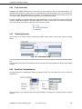
8.5.5 Tunneling Setup box
This box helps you to create a tunneling communication between remote modules (unicast) using “Inter-Port” tunneling
feature.
Fig. 29: Tunneling Setup
The way the interface is done helps you understanding the path of incoming and outgoing tunneling data, regarding selected
port.
The next chapter of this manual will fully detail how to build tunneling communications between two devices in few illustrated
examples.
8.5.6 Serial Port Configuration box
The physical Serial Port of AVM500-ES is internally connected to port {B}. The control page of this port will so display an
additional box:
This box will helps you to configure properly the physical parameters of the serial port, in association with the Tunneling
Setup box.
AVM500-ES User’s Manual v2.1
AuviTran 2010
39
Tunneling – General information
9
TUNNELING – GENERAL INFORMATION
Since version 0x110B / 0x118B of AVM500-ES firmware, multiple tunneling communications can be built, depending on the
network architecture. This chapter will illustrate the more common cases that you can face when using an AVM500-ES.
9.1 Ex. 1: Communication between AVY16-ES100 and Serial Port
In this example, we want to build a tunneling between an AVY16-ES100, and AVM500-ES physical serial port. This can be
used to remote control Yamaha AD8HR that is not fed with AVKit.
9.1.1 AVY16-ES100 is plugged on port B
Remember that port B is the port that owns the physical serial port. In this example, the whole configuration will be made in
AVM500-ES Port B control page. What we want to do here is to redirect the Serial port stream to the AVY16-ES100 in LS9,
and the AVY16-ES100 stream back to the Serial port.
Let’s see how to handle the control page:
- The “Incoming Tunneling Data” is the data from the remote device, i.e. AVY16-ES100 in our example. It goes in port
B (because AVY16-ES100 is plugged on port B). We want this stream goes to AVM500-ES Serial port. That’s why
we choose “Serial Port” in “Egress Port for Tunneling” combo box.
- The “Incoming Port Data” is the “internal” AVM500-ES data coming from any Port from A to E, or from Serial Port. If it
is coming from another port, the configuration is made in the corresponding port (we will see an example just after).
In our case, this data is coming from Serial Port. That’s why we can see in “Serial Port Configuration” box that the
physical Serial port is redirected to “Port B”. We want to send this stream to the AVY16-ES100, that why we choose
“LS9-1” in “Tunneling Destination” combo box.
- Of course, to finish this configuration, we must go to AVY16-ES100 control page, and configure a Unicast up to
AVM500-ES Port B.
AVM500-ES User’s Manual v2.1
AuviTran 2010
40
Tunneling – General information
9.1.2 And if AVY16-ES100 is plugged on another port?
Let’s just see quickly what would be the configuration if AVY16-ES100 is plugged on port E, for example. This time, we will
have to go to both Port B and Port E control page. Let’s begin with Port E control page.
Here is how to handle the control page:
- The “Incoming Tunneling Data” is the data from the remote device, i.e. AVY16-ES100 in our example. It goes in port
E (because AVY16-ES100 is plugged on port E this time). We want this stream goes to AVM500-ES Serial port.
That’s why we choose “Serial Port” in “Egress Port for Tunneling” combo box.
- The “Incoming Port Data” is the “internal” AVM500-ES data coming from any Port from A to E, or from Serial Port. In
our case, this data is coming from Serial Port. This will be configured in Port B control page as it is Port B that own
Serial port parameters. We want to send this stream to the AVY16-ES100, that why we choose “LS9-1” in “Tunneling
Destination” combo box.
- Of course, to finish this configuration, we must go to AVY16-ES100 control page, and configure a Unicast up to
AVM500-ES Port E.
Now, go back to port B control page.
There is no Incoming Tunneling Data on this port. “Egress Port for Tunneling” is useless, so leave it to “Port B” that is default
setting. There is neither Outgoing data on this port, so leave “Tunneling Destination” to “Off”. The only thing to do, is to
redirect the Serial port to “Port E” in the “Serial Port Destination” combo box, that’s it!
AVM500-ES User’s Manual v2.1
AuviTran 2010
41
Tunneling – General information
9.2 Ex. 2: Multiple tunneling – Port dissociation
As detailed in chapter 15, dissociating ports allows multiple tunneling communications. We will see here an example with two
Yamaha consoles and two SB168 stage box.
All ports of the AVM500-ES are dissociated. The goal here is to make a path between LS9 #1 and SB168 #1 and another
between LS9 #2 and SB168 #2. Let’s proceed step by step:
1.
On LS9 #1 control page, create a unicast path (Tunneling Destination) to”AVM500 B”, Serial Mode set to “LS9
Mode”.
2.
On AVM500-ES Port B, open a path between LS9 #1 coming stream and distant port C.
AVM500-ES User’s Manual v2.1
AuviTran 2010
42
Tunneling – General information
3.
On SB168 #1 control page, create a unicast path to AVM500-C
4.
On AVM500-ES Port C, open a path between SB168 #1 coming stream and distant port B.
Of course, the configuration is exactly the same for the other couple of LS9 #2/SB168 #2 with their respective AVM500-ES
ports (D and E).
AVM500-ES User’s Manual v2.1
AuviTran 2010
43
Serial port Interpreter
10 SERIAL PORT INTERPRETER
Since AVM500-ES firmware version 0x110C/0x118C, back panel Serial Port embedded a command interpreter that allows
user to patch the matrix without using ES-Monitor. This feature was typically designed for remote control with Crestron®
control panels. Of course, any distant interface that is design to complies with interpreter protocol will suites.
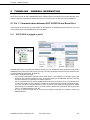
10.1 Enable Interpreter mode
To enable the command Interpreter, go to Port B control page, as it is port that own serial port. In the “Serial Port
Configuration”, select “Port A” in “Serial Port Destination” combo box, as this is the port that own the matrix patch. Please
also configure Baud Rate and Parity according to your remote control device.
AVM500-ES User’s Manual v2.1
AuviTran 2010
44
Serial port Interpreter
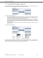
Now, in Port A control page, select “Serial Port” in “Egress Port for Tunneling” combo box. And finaly, turn-on interpreter by
checking “Serial Port Remote Ctrl” check-box. That’s it! Don’t forget to use a crossed RS232 cable between AVM500-ES and
your remote control device.
10.2 System architecture and conventions
The AuviTran AVM500-ES has 5xES100 ports named A, B, C, D and E. An AVM500-ES Port has 64 inputs and 64 outputs.
By convention, an inputs or an outputs of a port P is directly named by as simple basic letter {A, B, C, D, E} following by a 2
decimal digits. For instance:
A01 is interpreted as I/O 1 of port A
E62 is interpreted as I/O 62 of port E…
10.3 Programming interface
Any serial command is defined by a set of ASCII char following by <CR> or <CR><LF> ASCII sequence.
Five commands are defined today from the serial port patch:
•
•
•
•
•
Get serial protocol version
Set output patch
Mute output
UnMute output
Get output information
If an unknown command is sent, interpreter will return the ten first characters of the command, followed by « ? » character.
At end of each response, prompt character “>” is added after <CR>.
10.3.1 Get serial protocol version
Syntax:
V?<CR>
Answer:
V=X.Y<CR>>
Where X.Y is the version number of the serial protocol.
For instance:
Command send: V?
Answer received: V=1.0
AVM500-ES User’s Manual v2.1
AuviTran 2010
45
Serial port Interpreter
10.3.2 Set output patch
Syntax:
<Dest_Port><Dest_I/O>=<Source_Port><Source_I/O><CR>
Answer:
<Dest_Port><Dest_I/O>=<Source_Port><Source_I/O><CR>>
Where:
<Dest_Port> is a letter in {A, B, C, D, or E} that represents the destination port.
<Dest_I/O > is a 2 decimal digit that represents the destination output number.
<Source_Port> is a letter in {A, B, C, D, or E} that represents the source port.
<Source_I/O > is a 2 decimal digit that represents the source output number.
For instance:
Patch Output 12 of port A from input 5 of Port E:
Command send: A12=E05
Answer received: A12=E05
Patch Output 64 of port D from input 12 of Port C:
Command send: D64=C12
Answer received: D64=C12
10.3.3 Mute output
Syntax:
<Dest_Port><Dest_I/O>=M<CR>
Answer:
<Dest_Port><Dest_I/O>=M <CR>>
Where:
<Dest_Port> is a letter in {A, B, C, D, or E} that represents the destination port.
<Dest_I/O > is a 2 decimal digit that represents the destination output number.
For instance:
Mute Output 03 of port B:
Command send: B03=M
Answer received: B03=M
Mute Output 60 of port C:
Command send: C60=M
Answer received: C60=M
10.3.4 UnMute output
Syntax:
<Dest_Port><Dest_I/O>=U<CR>
Answer:
<Dest_Port><Dest_I/O>=M <CR>>
Or
<Dest_Port><Dest_I/O>=<Source_Port><Source_I/O><CR>>
Where:
<Dest_Port> is a letter in {A, B, C, D, or E} that represents the destination port.
<Dest_I/O > is a 2 decimal digit that represents the destination output number.
<Source_Port> is a letter in {A, B, C, D, or E} that represents the source port.
<Source_I/O > is a 2 decimal digit that represents the source output number.
M is a letter to defined Muted output (i.e. Not Patched)
For instance:
UnMute Output 03 of port B:
Command send: B03=U
Answer received: B03=M
UnMute Output 60 of port C:
Command send: C60=U
Answer received: C60=D03
AVM500-ES User’s Manual v2.1
AuviTran 2010
46
Serial port Interpreter
10.3.5 Get output patch
Syntax:
<Dest_Port><Dest_I/O>=?<CR>
Answer:
<Dest_Port><Dest_I/O>=<Source_Port><Source_I/O><CR>>
Or
<Dest_Port><Dest_I/O>=M<CR>>
Where:
<Dest_Port> is a letter in {A, B, C, D, or E} that represents the destination port.
<Dest_I/O > is a 2 decimal digit that represents the destination output number.
<Source_Port> is a letter in {A, B, C, D, or E} that represents the source port.
<Source_I/O > is a 2 decimal digit that represents the source output number.
M is a letter to defined Muted output (i.e. Not Patched)
For instance:
Get Patch information for Output 12 of port A:
Command send: A12?
Answer received: A12=E05
Get Patch information for Output 64 of port D
Command send: D64?
Answer received: D64=C12
Get Patch information for Output 03 of port B:
Command send: B03?
Answer received: B03=M
Get Patch information for Output 60 of port C:
Command send: C60?
Answer received: C60=M
AVM500-ES User’s Manual v2.1
AuviTran 2010
47
Serial port Interpreter
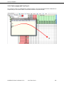
10.3.6 Patch example with Tera Term ®
This screenshot is made on an AVM500-ES with interpreter activated, and a serial cable plugged between AVM500-ES and
computer serial port. Tera Term ® software is used to send characters on computer serial port.
AVM500-ES User’s Manual v2.1
AuviTran 2010
48
ASIO Configuration
11 ASIO CONFIGURATION
Since AVM500-ES firmware version 0x110C/0x118C, Ports C, D and E can be swapped from EtherSound to ASIO stream.
When performing such a swap, the port is no longer an EtherSound Output or Input, but a regular Ethernet port. Plugging an
EtherSound compatible device on an ASIO port will have no effect, and EtherSound compatible device will NOT be
controllable through ES-Monitor.
An ASIO port is waiting for a computer connection. It can be a direct connection through a regular Cat5 cable, or it can go
through an Ethernet switch. A Gigabit switch may be recommended rather than a 100Mbits one, to be sure to not have
bandwidth limitation. For further information regarding ASIO technical configuration, please refer to “AuviTran Network ASIO
Streamer User’s Manual”.
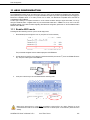
11.1 Enable ASIO mode
Activating the ASIO streaming mode on a port is a three-step process:
1.
Dissociate the port and configure it as an ‘In’ port (this is in Port A control tab):
The port will then disappear from the network displayed in AVS-ESMonitor.
2.
Connect the port to the PC (use a switch to connect both the ASIO port and the 3rd port of the AVM500-ES to the
PC). The port is visible again in AVS-ESMonitor.
3.
In the port’s control tab you can now enable the ASIO streaming mode:
Make sure to set the port to ‘In’ mode before connecting it to the host PC or to a switch. Failure to do so will
cause EtherSound traffic to be broadcasted and will have a severe impact on the network’s performance and
stability.
AVM500-ES User’s Manual v2.1
AuviTran 2010
49
ASIO Configuration
11.2 Disable ASIO mode
Follow the reverse path to disable ASIO streaming and return the port to its original configuration
1.
In the port’s control tab, disable the ASIO streaming mode.
2.
Disconnect the port from the control PC. The port disappears from the network displayed in AVS-ESMonitor.
3.
Associate the port with the port A. The port is visible again.
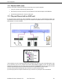
11.3 Play and Record with an ASIO port
To route audio from/to your ASIO port, simply use Netpatch, as you will have done in a regular EtherSound network. The
only difference is that the device plugged to your port is not an EtherSound compatible device, but a computer with an ASIObased application. Let’s see an example.
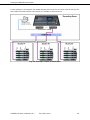
In this architecture, we have an AVA4-ES100 that brings its analogue audio inputs on port B, an AVP4-ES100 that can play
up to 4 channels on port D, and a computer with an ASIO based application plugged on port E. This port has been
configured as an ASIO port in its control page. Control PC is plugged on AVM500-ES 3rd Port. As you can see in this tree
view, the computer that plays/record is not visible, because there is no longer EtherSound stream on port E.
If you wan to record audio from AVA4-ES100, all you have to do is to patch its channels to port E.
If you want to play audio from computer to AVP4-ES100, all you have to do is to patch port E down to AVP4-ES100.
AVM500-ES User’s Manual v2.1
AuviTran 2010
50
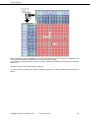
ASIO Configuration
Here is the NetPatch view of this architecture. You can see that AVA4-ES100 inputs are routed up to AVM500-B. Then,
channels from B are redirected to AVM500-E where recording computer is plugged.
In the other way, channels played from computer on port E are redirected to AVM500-C. Then AVP4-ES100 is patched to
listen to port C.
Everything is done as it was a regular EtherSound network!
For further information regarding ASIO technical configuration, please refer to “AuviTran Network ASIO Streamer User’s
Manual”.
AVM500-ES User’s Manual v2.1
AuviTran 2010
51
Auxiliary Power Supply – Firmware Update
12 AUXILIARY POWER SUPPLY
AVM500-ES provides another source of power supply, to improve the reliability of the system. It allows you to have two
distinct power supply sources, for redundancy solutions. When both power supply units (PSU) are plugged, AVM500-ES
compare them, and always choose the best. In case of failure of one PSU (or associated electrical network), AVM500-ES will
so continue to work.
Auxiliary PSU (ref. AVPSAUX-E45/EB) is validated and provided by AuviTran only. Please contact us if you want to integrate
the redundant PSU in your system.
http://www.auvitran.com
13 FIRMWARE UPDATE
To upgrade your AVM500-ES with new firmware release, please download the ES-Firmware Updater software on AuviTran’s
web site. You can also check periodically on the web site for new firmware release.
Please follow the steps below to put your device into a coherent mode for firmware upgrade.
-
First of all, unplug all devices that may be connected to the AVM500-ES, and plug your computer on port
{Ain}.
-
Then, ensure that all {B, C, D, E} ports are not dissociated (via ES-Monitor). In this case, the firmware
updater won’t be able to access to the devices. If needed, re-associate ports. For AVM500-ES/3Ports,
only ensure that ports B and C are not dissociated.
-
icon in ES-Monitor. You will have to re-set your
Save to non-volatile memory by clicking the
previous configuration after the update, and save it again with the same icon.
-
Finally, put dip switch #1 to “ON”.
You are now ready to upgrade the device properly and at a maximum speed. Please read the ES-Firmware Updater manual
to handle it properly.
AVM500-ES User’s Manual v2.1
AuviTran 2010
52