1
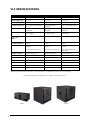
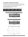
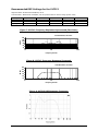
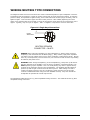
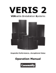
VLF Series
Versatile Low Frequency Systems
Models:
VLF208B / VLF208W
VLF212BI / VLF212WI
VLF212BP
Operation Manual
EC STATEMENT OF CONFORMITY
This document confirms that the range of products of Community Professional Loudspeakers bearing the CE
label meet all of the requirements in the EMC directive 89/336/EEC laid down by the Member States Council
for adjustment of legal requirements. Furthermore, the products comply with the rules and regulations
referring to the electromagnetic compatibility of devices from 30-August-1995.
The Community Professional Loudspeaker products bearing the CE label comply with the following
harmonized or national standards:
DIN EN 55013:08-1991
DIN EN 55020:05-1995
DIN EN 55082-1:03-1993
The authorized declaration and compatibility certification resides with the manufacturer and can be viewed
upon request. The responsible manufacturer is the company:
Community Light & Sound
333 East 5th Street
Chester, PA 19013
USA
TEL: 1-610 876-3400
FAX: 1-610 874-0190
Chester, PA USA December 2011
Notice: Every effort has been made to insure that the information contained in this manual was complete
and accurate at the time of printing. However, due to ongoing technical advances, changes or modifications
may have occurred that are not covered in this manual.
Community VLF Series – Operation Manual - Page 2
TABLE OF CONTENTS
INTRODUCTION ........................................................................................................ 4
IMPORTANT SAFETY INFORMATION.............................................................................. 4
UNPACKING AND INSPECTION .................................................................................... 5
VLF SPECIFICATIONS ................................................................................................ 7
ELECTRONIC CONTROLLER OPTIONS............................................................................ 8
RECOMMENDED DSP SETTINGS FOR THE VLF208 ........................................................................... 8
RECOMMENDED DSP SETTINGS FOR THE VLF212 ........................................................................... 9
DYNA-TECHTM SUBWOOFER PROTECTION SYSTEM ......................................................... 10
HIGH-PASS FILTERS................................................................................................. 11
CONNECTING THE AMPLIFIER TO THE LOUDSPEAKER: VLF208 AND VLF212I ..................... 11
SELECTABLE HIGH-PASS OUTPUTS: VLF212P ............................................................... 13
CONNECTING THE AMPLIFIER TO THE LOUDSPEAKER: VLF212P....................................... 15
WIRING NEUTRIK TYPE CONNECTORS ......................................................................... 16
RIGGING / SUSPENSION AND SAFETY ......................................................................... 17
VLF MOUNTING BRACKETS AND ACCESSORIES............................................................. 18
VLF-Y208 MOUNTING YOKE BRACKET ...................................................................................... 18
VLF-SAB STEERED ARRAY BRACKET ........................................................................................ 18
DIMENSIONAL DRAWINGS ........................................................................................ 19
WARRANTY INFORMATION AND SERVICE ..................................................................... 22
TABLE OF FIGURES
No.
Figure
Page
1
Physical Features of a VLF208
6
2
Physical Features of a VLF212I
6
3
Physical Features of a VLF212P
6
4
VLF208 Frequency Response Unprocessed (Raw Data)
8
5
VLF208 Frequency Response Processed
8
6
VLF208 DSP Frequency Response
8
7
VLF212 Frequency Response Unprocessed (Raw Data)
9
8
VLF212 Frequency Response Processed
9
9
VLF212 DSP Frequency Response
9
10
VLF208 Input Panel
11
11
VLF212I Input Panel
12
12
Graph Depicting Response of High-Pass/Flat Switch
13
13
VLF212P Input Panel
15
14
Single amp Connections
16
15
VLF-Y208 Mounting Yoke
18
16
VLF-SAB Steered Array Bracket with VLF208
18
17
VLF-SAB Steered Array Bracket with VLF212
19
18
VLF208 Dimensions
19
19
VLF212I Dimensions
20
20
VLF212P Dimensions
21
Community VLF Series – Operation Manual - Page 3
VLF SERIES OPERATION MANUAL
INTRODUCTION
Thank you for selecting Community’s Versatile Low Frequency (VLF) Series. VLF is a series of powerful and
innovative new low frequency subwoofers that feature a compact, low-profile design ideal for theaters,
restaurants, auditoria, houses of worship, schools and other venues, fitting into areas where larger
subwoofers are impractical. VLF Series loudspeakers are designed for demanding day-to-day use in a wide
range of fixed and portable installations. Their high quality driver components are housed in rugged,
acoustically inert enclosures equipped with rigging fittings.
This manual covers the VLF208 compact dual 8-inch micro subwoofer, the VLF212I compact dual 12-inch
subwoofer for permanent installation, and the VLF212P “portable” version of the VLF212I with built-in
handles and pole mount socket.
VLF subwoofers offer numerous features and advances in technology. Some of these include:
Low profile design, small footprint
Designed to work as a traditional subwoofer or in steered bass arrays
DYNA-TECHTM protection circuitry reduces the likelihood of driver damage under abusive conditions.
Load-rated threaded rigging fittings for safe & easy rigging.
NL4-compatible locking connector with terminal strip for easy connectivity.
Suitable for in-wall, under-seating, under-stage and other “hidden” LF applications
Optional factory designed mounting brackets available from stock.
Available in black or white finish at no additional cost.
IMPORTANT SAFETY INFORMATION
Always follow these basic safety precautions when using or installing VLF loudspeakers and accessories:
1.
2.
3.
4.
5.
Read these instructions.
Keep these instructions.
Heed all warnings.
Follow all instructions, particularly those pertaining to rigging, mounting, hanging and electrical
connections.
Only use accessories that are specified and approved by the manufacturer.
The terms CAUTION, WARNING, and DANGER are used throughout this manual to alert the reader to
important safety considerations. If you have any questions or do not understand the meaning of these
terms, do not proceed with installation. Contact your local dealer, distributor, or call Community directly for
assistance. These terms are defined below:
CAUTION: describes an operating condition or user action that may expose the equipment
or user to potential damage or danger.
WARNING: describes an operating condition or user action that will likely cause damage to
the equipment or injury to the user or to others in the vicinity.
DANGER: describes an operating condition or user action that will immediately damage the
equipment and/or be extremely dangerous or life threatening to the user or to others in the
vicinity.
The loudspeakers described in this manual are designed to be ‘flown’ or suspended for maximum acoustical
performance using a variety of rigging hardware, means, and methods in some applications. It is essential
that all installation work involving the suspension of these loudspeaker products be performed by
competent, knowledgeable persons who understand safe rigging practices. Severe injury and/or loss of life
may occur if these products are improperly installed. Please read the section on rigging for additional
information.
Community VLF Series – Operation Manual - Page 4
UNPACKING AND INSPECTION
VLF loudspeakers are inherently rugged and are carefully packed in sturdy cartons. However, it is wise to
thoroughly inspect each unit after it has been removed from the packaging, as damage could occur during
shipping.
Please note that once the shipment has left your dealer or the Community factory, the responsibility for
damage is always borne by the freight company. If damage has occurred during shipping, you must file a
claim directly with the freight company. It’s very important to contact the freight company as soon as
possible after receiving your shipment, as most freight companies have a short time limit within which they
will investigate claims. Make sure to save the carton and the packing material, as most claims will be
denied if these materials are not retained. Your Community dealer and the factory will try to help in any
way they can, but it is the responsibility of the party receiving the shipment to file the damage claim.
It’s always a good idea to retain the carton and packing materials indefinitely, if possible, in the event that
the unit may need to be returned to your dealer or distributor for repair in the future.
Each shipping carton contains the following items:
VLF Loudspeaker System (Qty 1)
Owner’s Guide (Qty 1)
Warranty Card (Qty 1)
DANGER: VLF rigging fittings are rated at a Working Load Limit (WLL) of 100 lbs (45.4kg)
with a 10:1 safety margin. No single rigging fitting should ever be subjected to a load that
is greater than this stated limit. Failure to heed this warning could result in injury or even
death!
IMPORTANT: The flat-head Allen-drive rigging screws that come installed in each
enclosure must either be replaced with rigging brackets and threaded fasteners, or they
must be kept in place to seal the enclosure from air leaks. If the rigging fittings do not
remain sealed, air leaks will occur in the enclosure that will compromise the low-frequency
performance with distortion and reduced output.
Community VLF Series – Operation Manual - Page 5
Figure 1: Physical Features of a VLF208
RECESSED FOOT-MOUNTING
LOCATIONS (4) FOR WHEN THE
VLF208 IS USED VERTICALLY
Figure 2: Physical Features of a VLF212I
Figure 3: Physical Features of a VLF212P
8 MOUNTING POINTS
(4 ON EACH SIDE)
Community VLF Series – Operation Manual - Page 6
VLF SPECIFICATIONS
Model
VLF208
VLF212I
VLF212P
Loudspeaker Type
Compact Subwoofer
Compact Subwoofer
Compact Subwoofer
Driver Complement
LF: 2 x 8"
LF: 2 x 12"
LF: 2 x 12"
Operating Range
55 Hz – 400 Hz
35 Hz – 200 Hz
35 Hz – 200 Hz
Frequency Response
60 Hz – 160 Hz ±1dB processed
43 Hz – 160 Hz ±2dB
processed
43 Hz – 160 Hz ±2dB processed
Input Ratings
300W RMS
750W PGM
300W RMS
750W PGM
300W RMS
750W PGM
Sensitivity 1W/1m
95 dB SPL (63 Hz – 160 Hz 1/3
octave bands)1
97 dB SPL (50 Hz – 160 Hz
1/3 octave bands)1
97 dB SPL (50 Hz – 160 Hz 1/3
octave bands)1
Maximum SPL
Continuous
Peak
120 dB SPL / 127 dB SPL (peak)
122 dB SPL / 129 dB (peak)
122 dB SPL / 129 dB (peak)
Nominal Impedance
4 Ohms
4 Ohms
4 Ohms
Input Connection
(1) NL4-compatible locking
connector
(1) NL4-compatible locking
connector
(2) NL4-compatible locking
connector
(1) 2 conductor barrier strip
(1) 2 conductor barrier strip
(2) ¼” jack with high-pass
output switch
Rigging Provisions
(8) M10 hang points
(12) M10 hang points
(8) M10 hang points
Construction
11-ply cross laminated birch
11-ply cross laminated birch
11-ply cross laminated birch
Finish
Black or white paint finish
Black or white paint finish
Black paint finish
Height
8.25 in / 210 mm
20 in / 508 mm
20 in / 508 mm
Width
21.75 in / 552 mm
21.75 in / 552 mm
21.75 in / 552 mm
Depth
13 in / 330 mm
20 in / 508 mm
20 in / 508 mm
Net Weight
42 lbs / 19.1 kg
88 lbs / 39.9 kg
88 lbs / 39.9 kg
1
Half Space pink noise measurement at 4 ft. (1.2m) at 25% power; extrapolated to 1m and an input of 2 Volts RMS.
Due to ongoing development, specifications are subject to change without notice.
VLF208
VLF212I
Community VLF Series – Operation Manual - Page 7
VLF212P
ELECTRONIC CONTROLLER OPTIONS
VLF subwoofers are intended to be controlled by a digital signal processor (DSP) that directly precedes the
power amplifier in the signal chain. The controller processes the audio signal to provide an optimized signal
to the loudspeaker under all operating conditions. This results in improved frequency response, maximized
power handling, lower distortion and increased protection for the loudspeaker components.
Recommended DSP Settings for the VLF208
High-Pass Filter: Linkwitz 48 dB/Oct, 55 Hz
Low-Pass Filter: Butterworth 48 dB / Oct, 200 Hz (Varies based on the full-range system used)
PEQ1
58 Hz
+9 dB
0.2 Oct
PEQ2
70 Hz
+5.5 dB
0.33 Oct
PEQ3
110 Hz
-2 dB
1 Oct
PEQ4
248 Hz
-7 dB
0.33 Oct
Figure 4: VLF208 Frequency Response Unprocessed (Raw Data):
10 Hz Resolution, 1/8 octave smoothing
dB SPL
100
90
80
70
10
100
1,000
Frequency in Hertz
Figure 5: VLF208 Frequency Response Processed:
10 Hz Resolution, 1/8 octave smoothing
100
dB SPL
Filter Type
Frequency
Gain
Slope/Q
90
80
70
10
100
1,000
Frequency in Hertz
Figure 6: VLF208 DSP Response Frequency:
Community VLF Series – Operation Manual - Page 8
Recommended DSP Settings for the VLF212
High-Pass Filter: Butterworth 48 dB/Oct, 35 Hz
Low-Pass Filter: Butterworth 48 dB/Oct, 200 Hz (Varies based on the full-range system used)
Filter Type
Frequency
Gain
Slope/Q
PEQ1
38 Hz
+4.5 dB
0.20 Oct
PEQ2
45 Hz
+2.5 dB
0.19 Oct
PEQ3
62 Hz
-3 dB
0.5 Oct
PEQ4
110 Hz
+1 dB
1 Oct
PEQ5
200 Hz
-7 dB
0.33 Oct
Figure 7: VLF212 Frequency Response Unprocessed (Raw Data):
10 Hz Resolution, 1/8 octave
dB SPL
120
110
100
90
80
70
10
100
1,000
Frequency in Hertz
Figure 8: VLF212 Frequency Response Processed:
10 Hz Resolution, 1/8 octave
dB SPL
120
110
100
90
80
70
10
100
Frequency in Hertz
Figure 9: VLF212 DSP Response Frequency:
Community VLF Series – Operation Manual - Page 9
1,000
DYNA-TECHTM SUBWOOFER PROTECTION SYSTEM
VLF208 and VLF212 loudspeakers employ Community’s advanced technology DYNA-TECH driver protection
system. Functioning as a multi-stage limiter, DYNA-TECH circuitry provides precise and repeatable
protection by reducing excessive power to the drivers under abusive conditions.
The limiting protects the drivers from damage due to excessive power levels being applied. This limiter is
based on an electromechanical relay driven through a voltage sensing circuit. The relay engages at a
predetermined voltage, corresponding to a power level that would otherwise cause driver damage. When
engaged, the relay introduces a bank of high-wattage resistors in series with the drivers. These resistors
cause a voltage drop to the drivers, thereby reducing the power applied to them. On the VLF212P, a red
LED on the rear panel indicates that this protection circuit has been engaged (the VLF208 & VLF212I do not
have this indication LED).
When the relay protection circuit is activated, there will be a noticeable drop in the system’s level
(approximately 3 to 4 dB). The red LED, as well as the drop in level, serves as a warning to the operator
that the loudspeaker is being overdriven. When this stage of protection is engaged, the level of the
console and/or the amplifier’s output to the system should be reduced.
IMPORTANT: If the operator continues to run the system at excessive levels, or worse, if
the operator raises the drive level to compensate for the drop in output caused by the
protection circuitry, eventually a second stage of protection will engage that shuts down the
system entirely (note that this additional stage of protection will never engage until after
the first stage has been triggered). If the system shuts down entirely, the operator can
immediately restore sound by simply reducing the drive level to the system.
Advantages of Community’s DYNA-TECH Circuitry
There are numerous advantages to this type of multi-stage protection circuitry. The trip point is pre-set to
engage at exactly the same time on all loudspeakers that are powered from the same amplifier. The initial
stages of DYNA-TECH protection circuitry do not rely on, and are not affected by, heat buildup. Some
manufacturers use circuit breakers that require heat buildup before they trip; this limits their ability to
protect a cold speaker. The trip points of such breakers are also affected by ambient temperature, their
own internal heating curves, and small variations in loudspeaker impedance or crossover component
tolerances, all of which can cause unpredictable behavior.
Because the first stage of Community’s DYNA-TECH circuit is not thermally sensitive, it reacts nearly
instantaneously to protect against an excessive increase in level. Moreover, the protection disengages
almost immediately when the drive level to the system is reduced; it is not necessary to wait for a circuit
breaker to cool down. This means that your loudspeaker can operate at its full dynamic range and still react
quickly to protect against excessive musical peaks, avoiding damage to the system. It also means that your
loudspeaker is protected from the moment the power amplifier is plugged in and turned on, regardless of
the ambient temperature.
As mentioned above, the protection circuitry provides a second level of protection for the entire loudspeaker
to guard it from severe misuse. If the system is operated in the first stage mode of protection for a long
period of time, or if the input level is increased to try to overcome the volume drop from the first-stage
protection circuitry, a solid-state circuit breaker will trip and remove all signal from the loudspeaker until the
input level is reduced.
Because this circuit breaker is heat sensitive, it provides a final level of protection that takes heat into
account as well as power. However, unlike most implementations of circuit breakers that take time to cool
down before resetting, DYNA-TECH circuits respond instantly to a reduction in level, restoring the system to
its full dynamic range without needing to wait for the circuit breaker to reset itself.
Community VLF Series – Operation Manual - Page 10
HIGH-PASS FILTERS
The use of an external, active high-pass filter to protect the cone drivers from excessive low-frequency
excursion is strongly encouraged. A high-pass filter will eliminate the potential of low-frequency modulation
from wind noise, turntable rumble, stage vibration, and other causes that result in a poorly defined and
‘muddy’ bass response. Additionally, a high-pass filter will avoid wasting amplifier power by keeping the
amplifier from attempting to reproduce frequencies below the loudspeaker’s intended operating range. The
table below shows the recommended filter settings:
Model
High-Pass Filter
VLF208 Subwoofer:
55 Hz, 24 dB/octave
VLF212I Subwoofer:
48 Hz, 24 dB/octave
VLF212P Subwoofer:
48 Hz, 24 dB/octave
CONNECTING THE AMPLIFIER TO THE LOUDSPEAKER:
VLF208 AND VLF212I
The VLF208 and VLF212I come with two methods of connecting the amplifier to the loudspeaker. One is an
industry standard NL4 type locking connector, and the other is a terminal strip. These two connectors are
wired in parallel with each other, on all models.
Figure 10: VLF208 Input Panel
The loudspeaker is intended to be connected directly to the amplifier.
Community VLF Series – Operation Manual - Page 11
Figure 11: VLF212I Input Panel
The loudspeaker is intended to be connected directly to the amplifier.
PIN Designations
For all models the pin designation is as follows:
NL4 Pin 1+ or the terminal screw labeled (+) connect to the positive (red) output of the amplifier.
NL4 Pin 1- or the terminal screw labeled (-) connect to the negative (black) output of the amplifier.
Note that the NL-4 and the terminal strip are wired in parallel, and that Pins 2+ and 2- on the NL4 connector
are not utilized.
CAUTION: Be sure to carefully observe polarity when wiring your loudspeakers. If one
loudspeaker is wired with the opposite polarity from another loudspeaker, acoustic
cancellation will occur. The result will be less acoustic power output than if only one
loudspeaker were used by itself.
Community VLF Series – Operation Manual - Page 12
SELECTABLE HIGH-PASS OUTPUTS: VLF212P
The VLF212P subwoofer is equipped with an industry-standard NL4-compatible locking connector wired in
parallel with a ¼” jack. A second NL4-compatible locking connector is provided, also wired in parallel to a
¼” jack. This second set of connectors is intended as OUTPUTS and are associated with the subwoofer’s
SWITCHABLE HIGH-PASS OUTPUT.
When the selector switch is set to the PARALLEL INPUT MODE (the down position), both the NL4compatible locking connector and the 1/4” jack function exactly as loop-thru connectors; in other words they
are simply wired in parallel with the INPUT CONNECTORS.
Conversely, when the selector switch is set to HIGH-PASS OUTPUT (the up position), a 1st order high-pass
filter (6 dB per octave) is inserted into the circuit. The filter has a corner frequency of 125 Hz with an 8 ohm
load.
Using the HIGH-PASS OUTPUT MODE inserts the HIGH-PASS FILTER as mentioned above, but it also
presents a higher impedance load to the amplifier. This can become quite important, particularly if a pair of
full-range loudspeakers and a subwoofer are being powered from a single amplifier channel. In the
PARALLEL INPUT MODE, the impedance of the combined load could become dangerously low for some
amplifiers, potentially causing the amplifier to shutdown or fail.
The following graph shows the difference in the total load impedance with the high-pass switch in the HIGHPASS and PARALLEL INPUT MODE positions. The lower line depicts the response with the switch in the FLAT
position where the load drops below 2 ohms between 30 – 50 Hz and again between 100 – 200 Hz,
potentially causing early clipping, amplifier shutdown, or even amplifier failure. The upper line depicts the
response with the switch in the HIGH-PASS position, where the load impedance has been increased by about
50% by the subwoofer’s internal crossover circuit, thereby protecting the amplifier from premature clipping
and potential failure.
Figure 12: Graph Depicting Response of HIGH-PASS / FLAT Switch
(Note: upper line depicts HIGH-PASS; lower line depicts FLAT)
HIGH-PASS position
FLAT position
Community VLF Series – Operation Manual - Page 13
In addition to presenting a more amplifier-friendly load, the HIGH-PASS OUTPUT also attenuates the lowfrequency energy that’s fed to the full-range loudspeaker. This reduces the demand on the full-range
loudspeaker’s woofer, thereby freeing up some additional power and headroom in the upper part of the bass
spectrum. Use of the HIGH-PASS OUTPUT will typically result in an overall flatter response, but with
slightly less total power available in the mid-bass portion of the audio spectrum.
The results you achieve will be strongly influenced by the relative locations of the full-range loudspeaker(s)
and the subwoofer(s), their position in relation to the walls, floor or ceiling, as well as the overall room
acoustics. For example, if a full-range model is stacked on a subwoofer, the combined response will be
different than if it is flown 15 or 20 feet over the subwoofer. We encourage you to experiment to obtain the
quality of sound that is to your liking.
IMPORTANT: The corner frequency of the built-in HIGH-PASS FILTER on the VLF212P
is load dependent (this is the case with all passive filters). This means that the frequency
will alter if the impedance of the load changes. For example, if two 8 ohm full-range
enclosures are connected to the high-pass output in parallel, the resultant 4 ohm load will
change the high-pass corner frequency to 250 Hz.
For exact control in balancing the relative levels of the subwoofer(s) and the full-range loudspeaker(s), we
recommend that separate amplifier channels be employed to power each unit individually. Moreover, if an
electronic active crossover is used to divide the signal to the subwoofer(s) and the full-range
loudspeaker(s), this will result in bi-amping the two systems. Bi-amping provides the benefit of reducing the
overall power demand on each amplifier channel while reducing intermodulation distortion.
Community VLF Series – Operation Manual - Page 14
CONNECTING THE AMPLIFIER TO THE LOUDSPEAKER:
VLF212P
Figure 13: VLF212P Input Panel
PIN Designations
In the Parallel Output Mode the pin designation is as follows:
NL4 Pin 1+ and the tip of the ¼” jack connect to the positive (red) output of the amplifier.
NL4 Pin 1- and the sleeve of the ¼” jack connect to the negative (black) output of the amplifier.
Internally, each of these pins are connected to the NL4 output connector, to the ¼” output jack, and to the
drivers in the subwoofer.
In the Hi-Pass Mode the pin designation is as follows:
NL4 Pin 1+ and the tip of the ¼” jack connect to the positive (red) output of the amplifier.
NL4 Pin 1- and the sleeve of the ¼” jack connect to the negative (black) output of the amplifier.
Either the NL4 or the ¼" jack on the right side of the input panel may be used as hi-pass outputs to drive
one or more full-range loudspeakers. These hi-pass outputs exhibit the response that is discussed in the
section of this manual entitled “SELECTABLE HIGH-PASS OUTPUTS: VLF212P.”
Community VLF Series – Operation Manual - Page 15
WIRING NEUTRIK TYPE CONNECTORS
The diagrams below show how connections are made to a Neutrik Speakon TM style loudspeaker connector.
Terminations may be soldered, or made by means of their built-in screw and pressure clamp. If using the
pressure clamp, it’s important to tighten it fully, then to wait about ten minutes (longer is better), then to
tighten it again. This is because copper wire flows under pressure. After initially tightening the screw
clamp, some minutes later the screw will no longer be as tight due to the effect of the compression on the
copper. Typically, only one cycle of “tighten – wait – re-tighten” is required for a secure connection.
Figure 14: Single Amp Connections
+
FROM
AMPLIFIER
1+
1-
22+
NEUTRIK SPEAKON
CONNECTOR -- NL4FC
DANGER: When wiring the amplifier(s) to the loudspeaker(s), always power-down the
amplifier(s) and disconnect their AC Mains plug(s). Many modern, high power amplifiers
can deliver enough voltage and current to cause a harmful or lethal electric shock. Shocks
from very low frequencies, such as kick drums, can cause the human heart to stop beating
at relatively low power levels.
WARNING: After wiring the amplifier(s) to the loudspeaker(s), first power up all devices
that are upstream of the amplifier, such as mixers, equalizers, compressor/limiters, etc.,
before powering-up the amplifier. This is to avoid passing any clicks or pops that may
originate in the upstream devices to the loudspeakers. The amplifier should initially be
powered-up with its gain controls turned all the way down. After making sure that a
continuous signal is present, such as a CD playing, slowly raise the level of the gain
controls to establish that the wiring has been installed correctly. Only then should the
loudspeaker be operated at normal output levels.
The VLF208 and VLF212I have one (1) NL4-compatible locking connector. The VLF212P has two (2) NL4compatible locking connectors.
Community VLF Series – Operation Manual - Page 16
RIGGING / SUSPENSION AND SAFETY
The terms “rigging”, “flying” and “suspension” are often used interchangeably in describing methods of
installing loudspeaker systems at elevated positions.
DANGER: The loudspeakers described in this manual are designed and intended to be
suspended using a variety of rigging hardware, means, and methods. It is essential that all
installation work involving the suspension of these loudspeaker products be performed by
competent, knowledgeable persons who understand safe rigging practices. Severe injury
and/or loss of life may occur if these products are improperly suspended.
DANGER: All rigging fittings must remain sealed with the included flat-head allen screws or
they must be fitted with properly rated optional mounting hardware. Any missing fasteners
will compromise the structural integrity of the enclosure and constitute a safety hazard. Do
not suspend this loudspeaker unless all fasteners are securely in place!
COMMUNITY RIGGING HARDWARE WARRANTY: Community warrants that its
loudspeaker systems and its optional mounting and rigging hardware have been carefully
designed and tested. Community loudspeakers may be safely suspended when each
loudspeaker model is suspended with Community-manufactured optional mounting and
rigging brackets specifically designed for use with that particular model of loudspeaker.
This warranty applies only for use under normal environmental conditions, and when all
loudspeakers, component parts, brackets and hardware are assembled and installed in
strict accordance with Community’s installation guidelines contained herein. Beyond this,
Community assumes no further or extended responsibility or liability, in any way or by any
means whatsoever. It is the responsibility of the installer to insure that safe installation
practices are followed, and that such practices are in accordance with any and all local,
state, federal, or other, codes, conditions, and regulations that may apply to, or govern the
practice of, rigging, mounting, and construction work in the relevant geographic territory.
Any modifications made to any parts or materials manufactured or supplied by Community
shall immediately void all pledges of warranty or surety, related in any way to the safe use
of those parts and materials.
WARNING - NON-COMMUNITY RIGGING HARDWARE: Non-Community hardware used
for rigging a VLF loudspeaker must be certified by the supplier for this use and must be
properly rated for safety.
Important Notes on Rigging Loudspeakers
There are three areas of responsibility for rigging loudspeakers. The first is the building structure. Always
consult with the building architect or structural engineer to assure the ability of the structure to support the
loudspeaker system. The second area of responsibility is the loudspeaker itself. Community certifies its
loudspeaker systems and rigging accessories for suspension when they are properly installed according to
our published guidelines. The third area of responsibility is everything between the loudspeaker and the
building structure and the actual process of installation. The installing contractor assumes this
responsibility. Loudspeaker rigging should be performed only by certified rigging professionals using
certified rigging hardware chosen for the specific application. Prior to installation, the contractor should
present a rigging plan, with drawing and detailed parts list, to a licensed structural engineer (P.E.) or
architect for written approval.
Community VLF Series – Operation Manual - Page 17
VLF MOUNTING BRACKETS AND ACCESSORIES
Below are descriptions of optional accessories manufactured by Community for use with VLF loudspeakers.
In this section the terms “suspension” and “fly” mean the same thing: to elevate the loudspeaker enclosure
above the ground surface. Consult the user’s guide included with each part for detailed safety instructions.
It is the responsibility of the installer to insure that safe installation practices are followed. Installation of
loudspeakers should only be performed by trained and qualified personnel. It is strongly recommended that
a licensed and certified professional structural engineer approve the mounting design.
IMPORTANT: All rigging fittings should remain sealed, otherwise air leaks will occur in the
enclosure that can compromise the low-frequency performance with distortion and reduced
output.
WARNING: VLF rigging fittings are rated at a Working Load Limit of 100 lbs (45.4kg) with
a 10:1 safety margin. No single rigging fitting should ever be subjected to a load that is
greater than 100 lbs. Failure to heed this warning could result in injury or death!
VLF-Y208 Mounting Yoke Bracket
The VLF-Y208 yoke bracket is designed to mount the VLF208 subwoofer in either a vertical or horizontal
orientation. It is engineered to provide a high margin of safety when supporting the VLF208 subwoofer.
Yokes are manufactured of steel, covered with a durable powder-coat finish, and are available in either black
or white to match the color of the enclosure.
Figure 15: VLF-Y208 Mounting Yoke
VLF-SAB Steered Array Bracket
The VLF Steered Array Bracket enables the construction of cardioid bass arrays, steered bass arrays, or
vertical bass columns of VLF212 and VLF208 subwoofers, or combinations of both. Designated the VLFSAB, it is intended for use only with Community’s VLF212 and VLF208 subwoofer systems, which share a
common width of 21.75 inches.
Figure 16: VLF-SAB Steered Array Bracket with VLF208
Community VLF Series – Operation Manual - Page 18
Figure 17: VLF-SAB Steered Array Bracket with VLF212
DIMENSIONAL DRAWINGS
Figure 18: VLF208 Dimensions
TOP VIEW
9.691"[246.16]
9.691" [246.16]
(4) M10 HANG POINTS
SPEAKER ACCESS PANEL
5.316"[135.03]
13.000" [330.2]
5.316"[135.03]
4.000" [101.6]
4.500"[114.3]
21.750" [552.45]
4.500"[114.3]
4.000" [101.6]
M10 HANG
POINTS
FRONT
FRONT
M10 HANG
POINTS
PORT
8.250"[209.55]
FOOT RECESS
4.465" [113.42]
4.465"[113.42]
RIGHT
SIDE
LEFT SIDE
BOTTOM
LEFT SIDE VIEW
FRONT VIEW
RIGHT SIDE VIEW
FEET
TOP
RIGHT SIDE
BOTTOM VIEW
BOTTOM
Community VLF Series – Operation Manual - Page 19
REAR VIEW
Figure 19: VLF212I Dimensions
21.750"[552.45]
20.000"[508]
4.000"[101.6]
2.209"[56.1]
8.000"[203.2]
TOP VIEW
FACE
2.209"[56.1]
2.250"[57.15]
(6) M10
HANG
POINTS
20.000"[508]
10.299"
[261.6]
SPEAKER
ACCESS
PANEL
2.250"[57.15]
FRONT VIEW
SIDE VIEW
FACE
FEET
BOTTOM VIEW
Community VLF Series – Operation Manual - Page 20
REAR VIEW
Figure 20: VLF212P Dimensions
21.750"[552.45]
10.875"[276.23]
FOOT
RECESS
20.000"[508]
10.000"[254]
2.209"[56.1]
TOP VIEW
2.209"[56.1]
FACE
2.250"[57.15]
(4) M10
HANG
POINTS
20.000"[508]
SPEAKER
ACCESS
PANEL
2.250"[57.15]
SIDES
FRONT VIEW
FACE
FEET
BOTTOM VIEW
Community VLF Series – Operation Manual - Page 21
BACK VIEW
WARRANTY INFORMATION AND SERVICE
Transferable Warranty "(Limited)” Valid in the USA Only
Community loudspeaker systems are warranted in the USA to be free from manufacturing defects in
materials and workmanship for a period of five years, as determined by one of the following two methods,
whichever is longer:
Starting from the date of retail purchase, as noted on the sales receipt from an authorized Community
dealer,
OR
Starting from the date of manufacture, determined by the serial number, if the sales receipt is not available.
This warranty applies to the product; therefore, the remainder of the warranty period will be automatically
transferred to any subsequent owner.
This warranty applies only to failure of a Community loudspeaker caused by defects in materials and
workmanship during the stated warranty period. It does not apply to a unit that has been subjected to
abuse, accident, modification, improper handling/installation, or repairs made without factory authorization
or by anyone other than authorized Community Field Service Stations. This warranty is void if the serial
number has been defaced, altered or removed.
Products covered by this warranty will be repaired or replaced at the option of Community, without charge
for materials or labor, provided all the terms of this warranty have been met.
Obtaining Warranty Service
Warranty service may be obtained from the factory, or from an authorized Field Service Station.
To obtain factory or field warranty service for products purchased in the United States, return the product
for inspection to the address below, freight prepaid, in the original packaging. If the original packaging is
not available, call or write Community Warranty Service to obtain proper packaging materials or hand carry
the product to the nearest Field Service Station.
Factory Service Center:
Community Warranty Service
333 East Fifth Street
Chester, PA 19013-4511 USA
Field Service Station:
Call (610) 876-3400 for the nearest Authorized Field Service Station
For factory service, please call (610) 876-3400 for a Return Authorization (R/A) number before shipping.
The following information must be included in the package:
Owner’s complete name, daytime phone number, return street address and return authorization number.
The serial number of the product being returned and a copy of the retail sales receipt, if possible.
A complete description of the problem(s) experienced, including a brief description of how the equipment is
being used and with what brand, model and output power of amplifier.
Upon receipt, the service center will determine if the problem is covered under warranty. If covered under
this warranty, the product will be repaired or replaced, at Community’s option, and returned to the owner
freight prepaid. If the problem is not covered under this warranty, the owner will be notified of the problem
with an estimate of the repair costs.
Consequential and Incidental Damages: Community shall not be liable for any consequential or incidental
damages including, without limitation, injury to persons, property, or loss of use. Some states do not allow
the exclusion or limitations of consequential or incidental damages, so the above limitations and exclusions
may not apply.
Community VLF Series – Operation Manual - Page 22
This Community warranty is not extended by the length of time which an owner is deprived of the use of the
product. Repairs and replacement parts provided under the terms of this warranty shall carry only the
remaining portion of the warranty.
Community reserves the right to change the design of any product from time to time, without notice and
with no obligation to make corresponding changes in products previously manufactured.
While this warranty gives specific legal rights, there may also be other rights that vary from state to state.
No action to enforce this warranty shall be permitted ninety days after expiration of the warranty period.
Warranty Information and Service for Countries Other Than the USA
To obtain specific warranty information and available service locations for countries other than the United
States of America, contact the authorized Community Distributor for your specific country or region.
Community VLF Series – Operation Manual - Page 23
Community Professional Loudspeakers
333 East Fifth Street, Chester, PA 19013-4511 USA
Tel: 1-(610) 876-3400 | Fax: 1-(610) 874-0190
www.communitypro.com
© 2012 All Rights Reserved
21AUG2012