1
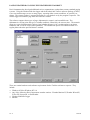
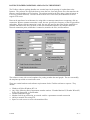
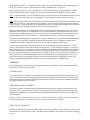
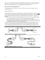
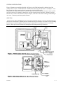
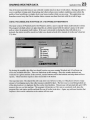
PAGING WEATHER DATA USING THE WEATHERLINK TOOLBOX™
Davis Instruments has developed additional tools to communicate weather data to many standard paging
systems. Using the WeatherLink data logger and the WeatherLink Toolbox software package (#7802),
a user can send messages to one or many pagers, reporting either current conditions, or specially set
alarms. The current weather is reported according to a set schedule set by the program’s operator. The
alarms trigger an automatic page when the limits are reached.
The software supports three types of page, alphanumeric, numeric, and an audible tone. The
alphanumeric version prints the type of weather condition, followed by the current value. The numeric
pager uses a pre-defined numeric code to signal whether the page is for a routine update or an alarm
condition, and a code for each weather parameter. The audible tone option will sound an alarm on a
regular phone when the specified alarm is reached.
There are certain hardware and software requirements for the Toolbox software to operate. They
include:
•
•
•
•
Windows 95/98 or Windows NT 4.0
Any of the following Davis Instruments weather stations: Weather Monitor II, Weather Wizard II,
II-S or III, Perception, or GroWeather
WeatherLink/Data Logger
Modem
23 - 2
4/22/99
POSTING WEATHER CONDITIONS AND DATA VIA THE INTERNET
The Toolbox software package handles two essential steps in the posting of weather data to the
Internet. The software first polls the data to create the text, Java and picture files, then transfers the
files to a specified address or file location. The software transfers the files using a protocol known as
FTP (File Transfer Protocol). In order for the transfer to be successful, the destination site must
support FTP access.
Data can be transferred to an Internet site using either a constant connection or a temporary dial-up
connection. When a constant connection is used, the user specifies the frequency of the file generation
and update. When a dial-up connection is used, the user still specifies how often he/she would like to
generate and transfer the files, but then, on the user-determined schedule, the computer dials the
network connection point, establishes a connection, transfers the files, and disconnects.
The software comes with several templates for posting weather data and graphs. The user can modify
the templates provided or create his/her own.
There are certain hardware and software requirements for the Toolbox software to operate. They
include:
•
•
•
•
•
•
Windows 95/98 or Windows NT 4.0
Any of the following Davis Instruments weather stations: Weather Monitor II, Weather Wizard II,
II-S or III, Perception, or GroWeather
WeatherLink/Data Logger
Modem for dial-up connection, or network card for a permanent network connection
Ability to transfer files using FTP
Space on a web server to receive the transferred files
4/22/99
23 - 3
Example: Typical Home Usage
The Toolbox software performs the following steps to post data to the web site:
1. Read Data from the Station
Reads data from the weather station
Downloads archived records
2. Create Files
Data file created from the WeatherLink data logger
Two graphs for each sensor stored as GIF image files
3. Generate Web Page
Replaces comment tags inside a HTML template with actual weather data
Saves it as another file
4. Transfer Files
Transfer the files to a web server using FTP. A typical location might look like:
ftp.davisnet.com/weather/.
23 - 4
4/22/99
WEATHERLINK® RADIO COMMUNICATIONS
4
Application Note
INTRODUCTION
The purpose of this note is to provide an overview of the alternatives available for communication of
WeatherLink data and control commands between a field weather station and the base computer. The
emphasis is on radio communications.
COMMUNICATION OPTIONS
Because the WeatherLink bus uses standard RS-232 conventions operating at 1200 or 2400 Baud, halfduplex, (see below for details) many communication modes may be used. The following four are presently
supported by Davis Instruments’ products:
Short-range Modem. A pair of Short-range Modems can transmit over a two-twisted-pairs cable for
distances of four miles or more, depending on wire gauge. The Davis model 7875 is an example.
Telephone (POTS). The conventional “plain old” telephone system may be used to “dial up” a weather
station from the base computer to transmit commands and receive data. Davis supplies a model 7870
Adapter to enable the connecting of the WeatherLink’s modular cable to the DB-25 connector of a standard
external telephone modem. The WeatherLink software supports entry of telephone numbers, automatic
scheduled dialing, and maintenance of databases for multiple stations.
Cellular Phone. A cellular phone modem-transceiver may be installed at the weather station, enabling it to
be called from any telephone for transferring of data. The Davis model 7652-003 includes an antenna and all
necessary components for connection of a Motorola CTM2400 3-Watt Cell-phone Transceiver to the
WeatherLink module. If the station is solar-powered it will be necessary to use a Timer, model 7690, or an
Alarm Output Module, model 7736, to control power to the transceiver. The Davis Instruments 7708/7711
solar-panel/battery combination provides sufficient power to support a small number of relatively short calls
per day under typical solar conditions.
Radio. Just about any radio modem/transceiver pair that can accept 1200- or 2400-Baud RS-232 data in a
data-only mode is suitable for use with WeatherLink data. The alternatives supported by Davis products and
the factors involved in selecting an approach are discussed below.
If there is a question regarding the selection or installation of communications equipment, we recommend
that the services of a communications consultant or technician be employed.
LINK CHANNEL DESCRIPTION
The WeatherLink data channel may be described as follows:
• Point-to-point, master-slave. The base station (computer with WeatherLink software) initiates all
communications. The GroWeatherLink, working with YDI or RF Neulink radios, can address a network
of field stations.
• RS-232, 1200 or 2400 Baud, switch-selectable.
• Half-duplex. The GroWeather and EnviroMonitor stations are true half-duplex. The Perception,
Wizard, and Monitor are designed to operate full-duplex, but they will operate on a half-duplex channel
if some limitations are accepted, the principal one being that if the user requests a long bulletin display it
cannot be interrupted. It must be allowed to complete.
• Data-only. No RTS/CTS handshake. 20 msec allowed for turn-time.
• CRC error-check. Data are error-checked in all systems. Control commands are error-checked by
GroWeather and EnviroMonitor stations.
• Power-conserving mode available.
12/16/97
4-1
COMMUNICATION PROTOCOL
A data transfer comprises the following sequence:
1. The master (base) station sends a control command or request for data (6 to 12 bytes, including CRC).
2. The field station responds with a single character: CRC ERROR or ACKNOWLEDGE valid request.
3. If data were requested, the field station then sends the data.
Any one of six types of data transfer may be requested. Example transfers and their typical lengths:
a. Read Archive Memory 32 data bytes + 2 CRC
b. Memory Dump
256 bytes + 2 CRC
c. Archive Dump
32k bytes in XMODEM blocks (128 bytes data + header & CRC).
If data are transferred at least once per Archive Interval, a single good Read Archive transfer each time is
sufficient to convey all necessary data.
If power conservation is not an issue, the station may be requested to send data continuously for real-time
display of the “bulletin.”
SELECTING A RADIO
In selecting a radio communication channel, the factors to be considered include cost, whether the
transmitters will be licensed or unlicensed, the range required, the nature of the transmission path, and the
frequency of data downloads versus the power available.
UNLICENSED, USA
Spread-spectrum. The frequency band of 902 to 928 MHz is available for unlicensed transmission in the
U.S. and Canada. Power output must be less than 1 Watt; the maximum allowed antenna gain for a 1-Watt
transmitter is 6 dBm.
At this frequency the transmission path must be line-of-sight: a completely unobstructed path between the
antennas of the communicating radios. Even vegetation can affect the transmission. Hills or buildings will
block transmission.
The spread-spectrum radio specifically supported by Davis Instruments is the YDI model RM910-DAVIS.
The radio is available from YDI; Davis Instruments provides two kits, each of which includes an antenna
and all necessary cables, connectors, and mounting hardware, plus power supply and programming disk.
One kit includes a 3 dB omni-directional antenna, the other an 8.5 dB directional antenna. A 12 dB antenna
is available from YDI (Model 918-10); if this is used the 7632-912 Installation Kit should be purchased from
Davis. The higher-gain antennas are permitted because the output power of the transmitter is 20 mW.
Information regarding antenna choice, model numbers, and procurement of radios is given below.
The range of the YDI radio is one-half to four miles, depending on the antennas used, as discussed below.
Unlicensed spread-spectrum transmission is also permitted in the U.S. and Europe at 2.4 GHz.
Transmissions at this frequency are even more demanding in their requirement for a line-of-sight path.
Low Power. Other frequency bands are available for low-power (10 to 20 mW) unlicensed transmission.
Davis Instruments does not directly support any of these at this time.
LICENSED, USA
To prevent interference between radios, the Federal Communications Commission (FCC) requires that a
specific frequency be assigned and a license issued before a narrow-band higher-power transmitter is placed
in operation. The license process takes two to six weeks. The FCC fee is $60; a fee of $160 is required by
the Personal Communications Industry Association, which assigns a recommended frequency and submits
4-2
12/16/97
the application to the FCC. In addition you may wish to use a consultant to handle the details and type the
forms. We used Josie Lynch, of Professional Licensing Consultants, Inc. (see page 9).
Before seeking a license you will need to know the emissions characteristic of your transmitter (see data
section, page 8) and the latitude, longitude, elevation, and planned antenna height of your base station.
VHF. Frequency bands of 129 to 174 MHz and 220 to 222 MHz are often used for data transmission. These
lower frequencies do not require line-of-sight paths, but the antennas are larger and more expensive.
UHF. The frequency band of 450 to 470 MHz is often used for agricultural and industrial data transmission.
Older radio types use a crystal to set the carrier frequency, so the frequency must be known at the time the
radio is ordered. Newer radios often use a synthesized frequency, so radios can be shipped off-the-shelf and
frequencies can be set through the data I/O port by a computer at any time.
The radio modem/transceiver recommended by Davis is the RF Neulink 9600 operating in the 450 to 470
MHz band. Davis supplies two Antenna Kits, each of which includes an antenna and all necessary cables,
connectors, and mounting hardware, plus a power supply and a programming disk for setting the frequency
and other characteristics. One Kit includes a 2 dB omni antenna and one a 10 dB directional antenna.
The range of the Neulink 9600 is typically up to 25 miles, depending on terrain and antenna height and type.
The range can be extended by installing a Neulink 9600 in repeater mode. It should be ordered in this
configuration from RF Neulink; Davis software does not support configuring of repeaters.
In some circumstances RF radiation from the Neulink’s omni-directional antenna can affect the weather
station’s measurement of temperature and barometric pressure. If data are being averaged over an interval
that is long with respect to the duration of radio transmission from the station, the effects will be negligible.
If radio transmission is continuous (as in the case of displaying the Bulletin), the data may be affected. In
this case it may be necessary to raise the antenna to a height of three feet (1m) or so above the console or 1.5
feet (0,5m) above the Sensor Mounting arm (mast-mount hardware is included in the Antenna Kit), or in
some other way place it at a distance from the station (see Site and System Configuration section). An
Industrial weather station has better immunity to such RF noise than does a Standard station.
ANTENNAS
In selecting antennas the principal considerations are transmission distance (range) and whether an omnidirectional or directional type is needed.
ANTENNA GAIN
An antenna’s “gain” is a measure of its ability to focus its transmitting energy and its receiving sensitivity.
Gain is measured in terms of decibels (dB), the logarithm of the factor of increase; every 6 dB added to the
total of antenna gains at both ends doubles the transmission distance (if factors such as antenna height and
propagation path characteristics permit).
OMNI-DIRECTIONAL ANTENNAS
As the name implies, an omni-directional antenna transmits and receives signals in all directions (in the
horizontal plane). Its usual form is essentially a vertical wire. If the station is a Base Station which must
communicate with Remote or Field Stations located in different directions, its antenna probably should be
omni-directional.
Omni (or “whip”) antennas tend to be lower in cost, have lower gain (lower range), and be more compact -less subject to damage by vandalism, ice, and wind. They do not need to be aimed.
DIRECTIONAL ANTENNAS
Directional antennas focus their transmitting energy and receiving sensitivity in one direction. This can have
two benefits: the effective range is longer, and the receiving antenna is less sensitive to interference coming
12/16/97
4-3
from other directions. The most common form is called a Yagi-Uda or just Yagi, after its inventors. The
antenna lobe, or focussed beam, lies in the direction in which the antenna boom is pointed.
The Yagi antenna’s beam width is expressed in degrees of angle between the two directions at which the
signal strength has fallen to –3dB compared with the center value. For example, the Davis 8.5 dB 900 MHz
antenna has a beam width of 65º when vertically-polarized. This means that the range will be reduced to
71% at angles of 32º either side of the aimed direction.
The antenna focus is not perfect, so it is possible for a Yagi antenna to communicate with antennas that lie
outside its main beam, but the effective range will be much lower.
Polarity. A Yagi antenna may be mounted in either of two orientations; the choice determines the polarity of
the transmitted signal:
a. If the antenna elements are vertical, the E-plane and the Polarity of the antenna are Vertical.
b. If the antenna elements lie in the horizontal plane, the E-plane and Polarity are Horizontal.
If two Yagi antennas are communicating with each other, either polarity may be used, but both must have the
same polarity. If another signal source is interfering, it may help to change the polarity. If a Yagi is
communicating with an omni, the polarity must be vertical.
ANTENNA HEIGHT
915 MHz signals (and, to a lesser degree, 450 MHz signals) tend to travel like visible light, in a straight path.
So there should be a line-of-sight unobstructed path between antennas of communicating stations. Because
the earth’s surface is curved, antennas must be elevated above the ground if they are to communicate at a
significant distance. A formula for estimating required antenna height above level ground is given in
2
References 1 and 2: H = D /2, where D = Distance in miles and H = height in feet. This formula gives the
following estimates:
Transmission distance
_Antenna Height_
3 miles
4,8 km
4.5 feet
1,4 m
4
7,3
8
2,5
8
14,6
32
9,8
Alternatives for antenna placement are discussed in the Site and System Considerations section.
RANGE
Table 1 gives estimated ranges for combinations of Davis-supplied antennas with line-of-sight paths between
them. Range estimates for other antenna gains may be found by using Figure 4 on page 11.
Table 1. Transmission distance, line-of-sight, vs. antenna type
--------------------------- Estimated Range ---------------------------YDI RM910
8.5 dB Yagi
Omni-to-Omni
0.9 mi 1.4 km
12 dB Yagi
Neulink 9600
4 mi.
6,5 km
Omni-to-Yagi
1.6 mi. 2,6 km
2.3
10 mi.
3,7
16 km
Yagi-to-Yagi__
3 mi.
4,8 km
7
25 mi.
11,2
40 km
POWER
AC POWER
If AC “mains” power is available at the field and base stations, the radios may be on continuously and the
WeatherLink operated in its normal modes.
SOLAR POWER
If the field station is operating on solar/battery power, it is necessary to switch power to the radio so it is off
most of the time in order to conserve the charge drained from the battery. The radio’s power is switched on
by the Timer or the Alarm Output Module for brief pre-determined intervals to allow communication.
4-4
12/16/97
The AOM enables the modem at 5 minutes past each even-numbered hour (according to the time clock in the
Console) and keeps it enabled for four minutes. When a communication is received, the modem remains
enabled during the data transfer and for two minutes thereafter; no communication is interrupted.
The Timer can be set to any intervals the user selects. Any radio communication in progress when the Timer
switches OFF will be interrupted. (Exception: a cell-phone call will not be interrupted.)
The “Charge Budget, “ discussed below, is one means of determining the amount of time that the radio may
be on each day.
CHARGE BUDGET
When using the radio in a solar/battery-powered station, one must limit the power drawn by the radio. This
means limiting the time that the radio is ON, enabled to receive messages, and -- in most cases -- limiting
even more severely the duration of transmissions.
The Charge Budget table (on page 10) gives a worksheet and an example of a charge budget, used to
calculate the daily battery drain for various ON and TRANSMIT durations. The sheet is also used to
estimate the daily charge available to the battery from the solar panel.
Charge Drain per Day
Lines A, B, C, and D of Table 2 sum up the current drains over the day.
A: A Monitor II station with Link draws 16 mA, a GroWeather or EnviroMonitor station draws 18 mA.
B: The Alarm Output Module, when in Power-Save mode, draws 2.4 mA continuously. The Timer current
may be considered zero when the relay is not energized; it draws 12 mA when the relay is closed.
C: This is the current drawn by the radio when on (see the equipment data section). The Neulink 9600
Modem/transceiver, for example, draws 100 mA when on. The YDI draws 180 mA.
D: This is the additional current drawn by the radio when transmitting. The Neulink draws an additional
800 mA. The YDI draws essentially zero additional current.
The total current drawn, in Amps (mA/1000), multiplied by the ON time in minutes gives the charge drain in
Amp-minutes.
The Example in Table 2 is for a GroWeather station using the Timer to turn the Neulink 9600 radio ON for
four six-minute periods each day. It assumes that two three-minute calls are made each day to read out the
data.
Charge Gain per Day
Lines E, F, G, and H provide parameters for calculation of the average charge that the solar panel provides to
the battery each day.
E: The charging current provided by the solar panel when solar irradiance is 1000 Watts per square meter.
The panel included with the Davis solar Power Kit provides 0.6 Amp.
2
F: The solar irradiance at solar noon at the station site, in W/m .
G. The length of the day, in hours.
H. A multiplier to account for cloudiness or other factors which may limit the average sunlight reaching the
panel throughout the day. Note that even during cloudy conditions at least 20% of the radiation usually
gets through.
The total charge gain is then -(Rated Panel Current) x (Peak Irradiance/1000) x 0.55 x (Day Length in minutes) x “Cloud Factor.”
The factor 0.55 includes battery efficiency and the integration of the solar cosine effect over the day.
The charge GAIN/DRAIN ratio gives the number of days of operating charge accumulated on an average
day.
Note that in GroWeather and EnviroMonitor stations the battery voltage is measured by the weather station
and reported via WeatherLink, so you can monitor the voltage and reduce or cease communication if it
12/16/97
4-5
drops too low. It is suggested that communication be limited whenever the battery voltage is less than 12.5
Volts; if the voltage drops below 12.0V, it is suggested that no communication be initiated until there is
reason to believe that the station has received charging sunlight for an hour or more.
SITE AND SYSTEM CONSIDERATIONS
This section provides a brief discussion of some of the alternatives for the physical design of the radio
communications link.
PROPAGATION PATH
The radio path between antennas should be unobstructed. Spread-spectrum 915 MHz transmissions require a
clear line-of-sight path. Such a path is highly desirable for UHF (450-470 MHz) signals. Achieving the clear
path may require positioning the antennas at a considerable height (as discussed above) or horizontal
distance from the weather station or base station computer. If this proves necessary, two alternatives are
available:
a. Use a long coaxial cable between the radio and the antenna. This may not be particularly desirable,
because signal strength is lost at the rate of 0.1 to 0.16 dB per foot of cable length.
b. Place the radio close to the antenna, and use a long data cable between the Weather Station (or the
Base Station Computer) and the radio. The RS-232 interface will drive a cable up to 50 feet in length;
a longer cable will require use of a short-range modem pair.
The 6-foot cables attached to Davis-provided antennas permit the antenna to be mounted up to two feet
(0,6m) above a Sensor Arm and System Shelter. Greater elevation can be obtained by using a 50-Ohm
co-ax extension cable (BNC female to BNC male). The connection should be protected from weather.
The 12-foot cable provided for the YDI 12-dB antenna permits a height of eight feet (2,4m) above the Arm.
4-6
12/16/97
SYSTEM CONFIGURATIONS
Figure 1 illustrates two possible radio links. In Figure 1a, the Field Station radio is within 8 feet of the
weather station console. The WeatherLink’s attached data cable plugs into the radio via an Adapter. At the
Base Station the radio is connected to the computer by a 40-foot modular cable.
In Figure 1b, the Field Station radio is located well above the console (at the top of a mast or tower or at the
peak of a barn roof, for example), connected by a 40-foot extension to the data cable. Similarly, the Base
Station radio is located some distance from the computer, in the attic of the office building or outbuilding or
on a tower. Short-range modems span the distance.
SHELTERS
A barn, shed, or other outbuilding may be used to house the Sensor Interface, Console, WeatherLink logger,
and radio of a field station. Similarly the base station radio may be installed in a residence or office building.
In such cases, no special equipment enclosures may be required. If no existing structures are available,
however, Davis provides two shelters for housing the radios and optional surge protectors.
12/16/97
4-7
System Shelter. The Complete-system Shelter is designed to provide weather protection for a complete
weather station, including the optional solar power regulator and battery and a radio. Figure 2 illustrates the
mounting in a System Shelter of a solar-powered station with YDI radio and an Alarm Output Module
providing the power conservation control.
Multi-Purpose (MP) Shelter. The MP Shelter is a smaller enclosure suitable for housing a Sensor Interface
and Console or a radio and its protector. The MP Shelter is useful when the radio must be located on the
antenna mast, exposed to weather. Figure 3 shows an RF Neulink radio mounted in an MP Shelter at the
base station with a Short-range Modem and Protector.
Small Surge-protector (SSP) Shelter. If it is necessary to add an extension co-ax antenna cable to a Davissupplied antenna with BNC connector, weather-proofing is necessary. The SSP Shelter will shield the
connection from rain or spray. Black electrical tape should not be used. Type N connectors are watertight.
DAVIS-SUPPORTED EQUIPMENT
The following radio and cell-phone products are specifically supported by the listed antenna kits and options
from Davis Instruments. Other products may well be suitable for a wireless communications need. For more
complete specifications see the individual product data sheet.
SPREAD-SPECTRUM, 902-928 MHz
Radio
YDI RM910-DAVIS
RF Output Power: 20 mW
Current Drawn: 180 mA, 12 VDC, receive and transmit.
Order from YDI (see page 9).
Antenna Kits
7632-003: Antenna Kit with 3dB omni (6-foot antenna cable)
7632-008: Antenna Kit with 8.5 dB Yagi (6-foot cable)
7632-912: Installation Kit for YDI 12 dB Yagi antenna (12-foot cable)
Options
7683:
Antenna Surge Protector and cable.
7708:
Solar Power Kit: (requires AOM or Timer)
NARROW-BAND UHF, 450 to 470 MHz
Radio
RF Neulink Neulink 9600
RF Output Power: 2 Watts, typical
Emissions: 16K0F1D, 16K0F2D
Current drawn: 100 mA, receive; 900 mA, transmit, at 10 – 15 VDC.
Order from RF Neulink (see page 9)
Antenna Kits
7642-002: 2 dB Omni (6-foot antenna cable)
7642-010: 10 dB Yagi (6-foot antenna cable)
Options
7683:
Protector and cable
7708:
Solar Power Kit (requires AOM or Timer).
CELLULAR TELEPHONE
Transceiver Motorola CTM 2400
RF Output Power: 3 Watts
Current drawn: 0.27 A, standby; 1.8 A, transmit.
Order from Motorola (see page 9). Requires service subscription.
Option: Handset. Permits voice calls to and from station.
Antenna Kit
7652-003. 3 dB omni (6-foot antenna cable)
Options
7681:
Protector.
7708:
Solar Power Kit (requires AOM or Timer).
4-8
12/16/97
The following shelters and accessories from Davis are compatible with the above products.
7724: Complete System Shelter
7728: Multi-Purpose (MP) Shelter
7768: Small Surge-protector (SSP) Shelter
7690: Timer
7736: Alarm Output Module
7875: Short-range Modem pair
7995: Omni Antenna Mast-mount Kit
SOURCES of COMMUNICATIONS EQUIPMENT and SERVICES
The list below identifies just a few of the many sources of equipment and services.
LICENSING SERVICES
Personal Communications Industry Association 703-739-0300
PO Box 25648
Alexandria, VA 22313-5648
Professional Licensing Consultants
301-309-2380
PO Box 1714
Rockville, MD 20849
RADIOS
YDI
703-237-9090
Model: RM910-DAVIS
103 Rowell Court
fax: 703-237-9092
Falls Church, VA 22046
RF Neulink
800-233-1728
Model: Neulink 9600
7610 Miramar Road
fax: 619-549-6345
450 – 470 MHz
San Diego, CA 92126-4202
CELLULAR TELEPHONES
Motorola Pan American Cellular Subscriber Sector
Model: CTM 2400
500 North State College Blvd., suite 1250
800-345-6864 ext 213
Orange, CA 92868
fax: 800-897-1829 ext 213
ANTENNAS and SURGE PROTECTOR
Cushcraft Corporation
603-627-7877
48 Perimeter Road, PO Box 4680
fax: 603-627-1764
Manchester, NH 03108
ANTENNA MASTS and MOUNTS
Radio Shack
800-843-7422
5-foot mast: #15-842
CABLES and CONNECTORS
50-Ohm cable,
Pasternak Enterprises
714-261-1920
BNC male to BNC female:
PO Box 16759
fax: 714-261-7451
#PE3047-xx,
Irvine, CA 92623
xx = length in inches.
SURGE PROTECTORS
PolyPhaser Corporation
702-782-2511
PO Box 9000
fax: 702-782-4476
Minden, NV 89423-9000
LIGHTNING ARRESTORS and GROUNDING EQUIPMENT
Harger Lightning Protection, Inc.
800-842-7437
1066 Campus Drive
fax: 708-362-3519
Mundelein, IL 60060
Thompson Lightning Protection, Inc.
612-455-7661
901 Sibley Highway
fax: 612-455-2545
Saint Paul, MN 55118-1792
12/16/97
4-9
SOLAR/BATTERY CHARGE BUDGET WORKSHEET
CHARGE DRAIN per DAY
Current
ON Time
(Amps)
(min/hour)
A. Station
_____
60
B. AOM or Timer
_____
C. Radio on
D. Transmit add
_____
_____
DRAIN
(min/day)
(Amp-min)
1440
______
______
_____
______
______
______
_____
_____
______
______
TOTAL DRAIN/DAY = A + B + C + D = ______ Amp-minutes
CHARGE GAIN per DAY
E. Solar Panel Current @ 1000 W/m2
_____ Amps
F. Peak Solar Irradiance
_____ Watts/m2
G. Day Length
H. Cloud Factor
_____ hours
_____
TOTAL GAIN/DAY = E (F/1000) x .55 x 60G x H =
_____ Amp-minutes
GAIN/DRAIN = ____
SOLAR/BATTERY CHARGE BUDGET Example: GroWeather with Timer and UHF Radio
CHARGE DRAIN per DAY
Current
(Amps)
A. Station
0.018
B. AOM or Timer
0.012
C. Radio on
0.100
D. Transmit add
0.800
ON Time
(min/hour) (min/day)
60
1440
24
24
6
TOTAL DRAIN/DAY = A + B + C + D =
CHARGE GAIN per DAY
E. Solar Panel Current @ 1000 W/m2
0.6 Amps
F. Peak Solar Irradiance
1000 Watts/m 2
G. Day Length
10 hours
H. Cloud Factor
0.75
TOTAL GAIN/DAY = E (F/1000) x 0.55 x 60G x H = 148.5 Amp-min.
4 - 10
DRAIN
(Amp-min)
25.9
0.3
2.4
4.8
33.4 Amp-minutes
GAIN/DRAIN = 148.5/33.4 = 4.5
12/16/97
REFERENCES
1. NLR Series Technical Notes. Aerotron-Repco Systems , Inc., Orlando, FL (Spread-spectrum issues)
2. Carr, Joseph. Practical Antenna Handbook, TAB Books, 1989.
12/16/97
4 - 13
MOVING WEATHER DATA FROM AN OLD PC TO A NEW PC
Application Note
34
®
With WeatherLink for Windows™
INTRODUCTION
To use your current WeatherLink weather station on your new PC, it will be necessary to transfer data files to the new
PC. The process may seem complicated, but is straight forward when you break the process down into its basic
components. This document will attempt to outline the process and the various components that may be needed.
Instructions are also provided to help you setup the connection to your weather station on your new PC.
GENERAL INSTRUCTIONS
If you installed WeatherLink on your old PC using the default setup, and you want the same installation on your new
PC, weather data can be transferred easily and simply:
Move The Weather Data Files:
• Copy the entire WeatherLink folder (with the name “WeatherLink”) from the C: drive on the old PC
• Paste it to the C: drive on the new PC. (You can paste the folder elsewhere if you prefer a different setup with
your new PC.)
Install WeatherLink:
• Place your WeatherLink software disc into the new PC’s CD drive to install the icons on the Start Menu and
desktop.
• For USB versions, be sure to have USB drivers checked when installing. This is an absolute requirement to
use the USB connection.
Connect Your Weather Station:
• Follow the “Getting Started Guide” instructions to tell you how to connect a Serial or USB connection to your
weather station and verify the connection is working.
If you understand how to do what was just described, then there is no need to read further. If you need more guidance,
continue reading.
DETAILED INSTRUCTIONS
Move the Weather Data Files
If both PCs are connected through a network with a file server or shared folders, it is possible to copy the WeatherLink
folder to the network temporarily and then to the new PC. If the local drive (commonly the C: drive) on both PCs is a
shared drive on the network this will not be necessary. Otherwise, an external USB drive or a writable-disc is probably
the best solution. For older PCs without a network connection, a writable disc drive, or USB ports (before Windows
98SE), the best solution may be to e-mail your files to yourself and open them on the new PC. If the total number of
files is too large to e-mail, you can get a program that shrinks the files to a manageable size. The most common
program of this type is WinZip. A free trial version can be downloaded from the Internet:
http://www.winzip.com/downwz.htm . If none of these solutions are viable, then you may need to consult someone
who can provide a more advanced solution.
Rev A 2/1/07
34 - 1
Using the Windows File System to Move Files
If you are inexperienced in using the Windows operating system, the following general guidelines should assist you in
copying the necessary files.
•
On your old PC, insert a blank disc into your writable disc drive or plug an external USB memory drive into
one of your USB ports. Note that for writable discs, a program may launch that allows you to use a “Browse”
function to select which folders or files to copy. In these cases, you may skip the following steps describing
what to do on the old PC.
•
Click the Start Menu and select My Computer (you may also be able to select My Computer from an icon on
your desktop)
•
Next, select the drive that you installed WeatherLink on. For default installations, this will be the C: drive.
34 - 2
Rev A 2/1/07
•
The following or a similar window should appear. Click on the WeatherLink folder to select it.
Rev A 2/1/07
34 - 3
•
Select Edit >> Copy from the menu. Right-clicking on the folder will also allow you to select the copy
function. Alternatively, you can left-click your mouse on the folder and hold it down while you drag this
folder to your USB drive, the drive containing your writable disc, or the network location to which you want to
temporarily copy the folder.
•
Select your destination by opening another window (via the Start Menu >> My Computer as before) showing
the contents of your writable disc, USB drive, or network location
•
Once this window is open, select Edit >> Paste.
•
Now that the files are copied to a disc or USB drive, take it out of your old PC.
34 - 4
Rev A 2/1/07
•
Insert the written disc to a disc drive or the USB drive into a USB port on the new PC, or for network transfers,
open the network drive window. In most cases, a window listing the contents of your disc or USB drive should
automatically appear.
•
Repeat a similar process as described for copying the WeatherLink folder from the old PC: select Edit >>
Copy from the disc, USB drive, or network window and then Edit >> Paste in the C: drive window of your
new PC. Right-clicking on the WeatherLink folder will also allow you to select these functions.
Using E-Mail to Move Your Files
If you have a PC that lacks working USB ports (Windows versions earlier than 98 SE), a writable disc, a network
connection, or the new PC lacks a floppy drive, then e-mailing your files may be your next best solution.
•
Open an email in your email program. Enter your own email address in the To: field.
•
In the body of the email, attach the WeatherLink folder from your C: drive and click Send.
•
On your new PC, you may need to configure your e-mail settings before you can read that new e-mail. When
configured properly, you can open the e-mail you sent yourself with the WeatherLink folder in it.
•
Right-click on that WeatherLink folder as an attachment and select Save As. A window that allows you to
navigate to your C: drive will appear. Select the C: drive and click Save to save your WeatherLink folder on
your new PC’s C: drive.
INSTALL WEATHERLINK
If you are connected to a network or the PC was set up for you by someone else, make sure you have Administrator
privileges on your new PC. If not, you may not be allowed to install WeatherLink or it may only install in such a way
that it is only available when you are logged onto the PC via a password. Place your WeatherLink disc in your new
PC’s CD drive. This will install the shortcuts on your Start Menu and desktop. For USB versions, be sure to have
USB drivers checked when installing as shown below. This is an absolute requirement to use the USB connection.
This task is critical to using the USB version of WeatherLink and connecting your weather station to the new PC.
If you have lost your WeatherLink disc, you may download an upgrade version from our website provided that you
already have version 5.X: http://www.davisnet.com/support/weather/software.asp#vantagePro . Also, if you ever need
Rev A 2/1/07
34 - 5
to reinstall WeatherLink from scratch or you have a floppy disc version and lack a floppy drive on your PC, this is an
option.
If you have version 4.X or earlier, you can purchase an upgrade version for a reduced price:
http://www.davisnet.com/weather/products/software.asp .
CONNECT YOUR WEATHER STATION
If you have the Serial version of WeatherLink, and your new PC has a free serial port, then your task is complete. If
your new PC lacks serial ports (which is the case with most new PCs), then you can purchase the USB to Serial
Adapter, Part # 8434: http://www.davisnet.com/drive/products/drive_product.asp?pnum=08434 . This device
connects to the PC’s USB port at one end and the WeatherLink PC Serial adapter at the other.
34 - 6
Rev A 2/1/07