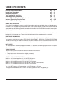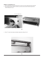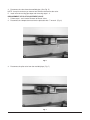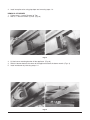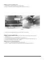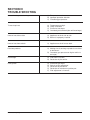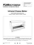
1
SERVICE MANUAL
ICM24,36,48,60 AND 72 CHEESE MELTERS
MODEL NO.
ICM24
ICM36
ICM48
ICM60
ICM72
ML-52470, 52476
ML-52471, 52477
ML-52472, 52478
ML-52473, 52479
ML-52474, 52480
MODEL ICM
VULCAN-HART
FORM 30915 (3-95)
COMPANY,
P.O.
BOX
696,
LOUISVILLE,
KY
40201-0696,
TEL. (502) 7 7 8 - 2 7 9 1
IMPORTANT FOR YOUR SAFETY
THIS MANUAL HAS BEEN PREPARED FOR PERSONNEL QUALIFIED TO INSTALL GAS
EQUIPMENT, WHO SHOULD PERFORM THE INITIAL FIELD START-UP AND
ADJUSTMENTS OF THE EQUIPMENT COVERED BY THIS MANUAL.
POST IN A PROMINENT LOCATION THE INSTRUCTIONS TO BE FOLLOWED IN THE
EVENT THE SMELL OF GAS IS DETECTED. THIS INFORMATION CAN BE OBTAINED
FROM THE LOCAL GAS SUPPLIER.
IMPORTANT
IN THE EVENT A GAS ODOR IS DETECTED, SHUT
DOWN UNITS AT MAIN SHUT-OFF VALVE AND
CONTACT THE LOCAL GAS COMPANY OR GAS
SUPPLIER FOR SERVICE.
FOR YOUR SAFETY
DO NOT STORE OR USE GASOLINE OR OTHER
FLAMMABLE VAPORS OR LIQUIDS IN THE
VICINITY OF THIS OR ANY OTHER APPLIANCE.
WARNING
IMPROPER INSTALLATION, ADJUSTMENT,
ALTERATION OR MODIFICATION, SERVICE OR
MAINTENANCE CAN CAUSE PROPERTY
DAMAGE, INJURY OR DEATH. READ THE
INSTALLATION, OPERATING AND MAINTENANCE
INSTRUCTIONS THOROUGHLY BEFORE
INSTALLING OR SERVICING THIS EQUIPMENT.
IN THE EVENT OF A POWER FAILURE, DO NOT
ATTEMPT TO OPERATE THIS DEVICE.
—2—
TABLE OF CONTENTS
Important safety information
Codes and standards information
Manual use information
Data plate information
Tools required for servicing
General appliance information
Section l Service Checks and Adjustments
Section ll Removal of Service Parts
Section lll Trouble Shooting
page
page
page
page
page
age
page
page
page
2
3
3
3
3
3
4-5
6-10
11
CODES AND STANDARDS
Vulcan-Hart Cheese Melters are to be installed in accordance with state and local codes, or in the absence of
local codes, with the National Fuel Gas Code, ANSI-Z223.1 (latest edition), available from the American Gas
Association, Inc., 1515 Wilson Blvd., Arlington, Va. 22209 and with ANSI-NFPA Standard #96 (latest edition),
Vapor Removal From Cooking Equipment, available from the National Fire Protection Association, Batterymarch
Park, Quincy, MA 02269.
For this appliance, clearance from combustible construction must be a minimum of 6" from the sides, 0" from the
back, and 4" from a counter top. There is no minimum clearance from noncombustible construction.
HOW TO USE THIS MANUAL
This manual is dedicated to the servicing of the Vulcan-Hart Co. ICM24,36,48,60 and 72 Cheese Melter.
The manual is divided into 3 sections, CHECKS AND ADJUSTMENTS, REMOVAL OF SERVICE PARTS AND
TROUBLE SHOOTING. For additional technical assistance refer to the service assistance number on the front
cover of this manual. Refer to parts manual to identify service replacement parts.
DATA PLATE
The data plate which identifies the appliance model no., device no., serial no., gas specification and agency
approvals is located on the appliance front cover in lower right corner.
TOOLS REQUIRED
Tools required to preform the service operations covered in this manual.
1. Standard set of hand tools.
2. Temperature tester (thermocouple or digital pyrometer).
3. Gas test kit.
GENERAL APPLIANCE INFORMATION
ICM24 is a 24" wide unit appliance (1) 20,000 BTU/HR burner.
ICM36 is a 36" wide appliance using (1) 30,000 BTU/HR burner.
ICM48 is a 48" wide appliance using (2) 20,000 BTU/HR burners.
ICM60 is a 60" wide appliance using (1) 20,000 and (1) 30,000 BTU/HR burners.
ICM72 is a 72" wide appliance using (2) 30,000 BTU/HR burners.
The 20,000 BTU burner is 15" long and the 30,000 BTU burner is 27" long.
The appliance manifold pressure is 5" W.C. for natural gas and 10" W.C. for propane gas.
—3—
SECTION I
SERVICE CHECKS AND ADJUSTMENTS
WARNING:
SHUT OFF GAS BEFORE SERVICING
VENTILATION CHECKS
Insure that adequate ventilation has been provided in accordance to all codes as stated on page 3 of this manual.
The vent for this appliance should be checked for restrictions every 6 months.
GAS SUPPLY CHECKS
If the gas supply piping is to be tested at a test pressure in excess of 1⁄2 psig(3.45Kpa), the appliance and its
individual shut-off valve must be disconnected from the supply line. If the gas supply piping system is to be tested
at a pressure equal to or less than 1⁄2 psig(3.45Kpa), the individual shut-off valve must be closed during testing.
REGULATOR VENT CHECK
1. With a screwdriver pry the plastic vent plug form the top of the regulator. (See Fig. 1)
2. Check vent for clogging of the breather vent screen. If screen is obstructed, clear the obstruction.
STORE LINE GAS PRESSURE CHECK
1. Turn main gas line off.
2. Tap the store line before the pressure regulator if a gas pressure tap and plug have not been supplied.
3. Install a single pilot valve fitting or similar device that will allow a gas pressure gauge to be connected to
the store line.
4. Connect the gas pressure gauge to the tapped valve device.
5. Turn the store main gas on.
6. Turn the unit gas on.
7. Take the store pressure reading. Store pressure should be at least 6" W.C. for natural gas and 11" W.C.
for propane gas.
8. If store pressure is not correct advise owner that the gas line pressure must be serviced for proper gas flow
before appliance service can be performed.
9. If store pressure is correct, continue checking by performing the appliance gas line check.
APPLIANCE GAS LINE CHECK
1. Turn appliance gas off.
2. Remove the burner knobs.
3. With a phillips head screwdriver remove (4) screws securing the front cover to the cheese melter.
4. From the front right side of the appliance follow the gas pipe to the gas line pressure tap.
5. Connect the gas meter to the line pressure tap.
6. Reinstall the burner knob handle and turn the appliance gas on.
7. Check the appliance pressure. Reading should be 5" W.C. for natural gas and 10" W.C. for propane gas.
PILOT LIGHTER TUBE CHECK
1. Follow steps 1-3 under Removal of Pilot Lighter Tube.
2. Check tube flame ports for blockage. If blockage is found, blow blockage out with water or air pressure
device. If these are not available try removing blockage with a small probing device. Do not force probe
device of a larger diameter through the port openings.
3. If blockage cannot be removed, replace the lighter tube.
4. To reinstall or replace lighter tube follow steps 1-3 under Removal of Pilot Lighter Tube in reverse order.
—4—
PILOT ORIFICE HOOD CHECK
1. Follow steps 1-3 under Removal of Lighter Tube.
2. With a 7⁄16" wrench remove the orifice hood.
3. Examine the hood and orifice opening for blockage.
4. If blockage is found, remove it using air or water pressure.
5. If blockage cannot be removed, replace the orifice hood.
6. Reinstall or replace orifice hood by reversing steps 1-2 above.
BURNER NOZZLE ORIFICE CHECK
Perform this procedure only after the pilot tube and burner orifice have been checked for blockages.
1. Follow steps 1-2 under Removal of Top Cover.
2. Follow steps 1-4 under Removal of Burner.
3. With a 5⁄8" wrench remove the compression nut and burner nozzle from the burner tube. (See Fig. 9)
4. Inspect the nozzle for blockage.
5. If blockage is found loosen the hood compression nut and remove the hood.
6. Clear blockage by blowing compressed air or water through the hood orifice opening.
7. Reinstall or replace the burner nozzle by reversing steps 1-3 above.
REGULATOR ADJUSTMENT
1. Follow steps 1-2 under Regulator Vent Check.
2. Follow steps 1-9 under Store line Gas Pressure Check and steps 1-7 under Appliance Gas Line Check.
3. If store pressure checks out but the appliance pressure is not correct, with a flat blade screwdriver remove
the regulator adjustment closure cap.
ADJUSTMENT
CLOSURE
CAP
VENT PLUG
Fig. 1
4. With a flat blade screwdriver, while still connected to the pressure gauge, rotate the regulator adjustment
screw clockwise to increase pressure and counterclockwise to decrease pressure. Appliance pressure
should be 5" W.C. for natural gas and 10" W.C. for propane gas. Adjust the regulator to obtain the required
reading.
PILOT VALVE ADJUSTMENT
1. Insert a small flat blade screwdriver through the adjustment hole. (See Fig. 4)
2. Turn the adjustment screw clockwise to increase gas flow and counterclockwise to decrease gas flow.
—5—
SECTION II
REMOVAL OF SERVICE PARTS
WARNING:
SHUT OFF GAS BEFORE SERVICING.
REMOVAL OF TOP
1. Push top back towards wall until the rear top mounting foot hits the stop angle. (Fig. 2)
STOP ANGLE
REAR MOUNTING FOOT
Fig. 2
2. Be sure that the top mounting foot has cleared the front top flange and lift the top
off of the appliance. (Fig. 3)
Fig. 3
—6—
REMOVAL OF BURNER VALVE
1. With a small blade screwdriver loosen the set screw in the valve knob and remove the knob.
2. With a phillips head screwdriver remove (4) screws at each corner of the front panel and
remove the panel. (Fig. 4)
PILOT ADJUSTMENT HOLE
Fig. 4
3. With a 5⁄8" wrench disconnect the elbow compression fitting. (Fig. 5)
Fig. 5
—7—
4. Disconnect the valve from the manifold pipe. (See Fig. 5)
NOTE: It may be necessary to remove heat shield to disconnect the valve.
5. Install new valve using pipe dope and reversing steps 1-4.
REPLACEMENT OF PILOT ADJUSTMENT VALVE
1. Follow steps 1 and 2 under Removal of Burner Valve.
2. Disconnect the compression nut from the pilot tube with 1⁄2" wrench. (Fig. 6)
Fig. 6
3. Disconnect the pilot valve from the manifold pipe. (Fig. 7)
Fig. 7
—8—
4. Install new pilot valve using pipe dope and reversing steps 1-3.
REMOVAL OF BURNER
1. Follow steps 1-2 under Removal of Top.
2. With a 7⁄16" wrench remove (2) nuts. (Figs. 8)
Figs. 8
3. Lift the burner mounting bracket off the appliance. (Figs. 8)
4. Slide the burner towards the center of the appliance and off the burner nozzle. (Figs. 9)
5. Install new burner by reversing steps 1-4.
Figs. 9
—9—
BURNER NOZZLE REPLACEMENT
1. To remove the burner nozzle follow steps 1, 2 and 3 under Burner Nozzle Orifice Check. (Fig. 10)
Fig. 10
2. Install new nozzle by reversing steps 1, 2, and 3 under Burner Nozzle Orifice Check.
— 10 —
REMOVAL OF PILOT LIGHTER VALVE
1. Follow steps 1-3 under Removal of Pilot Lighter Tube.
2. With a 1⁄2" wrench disconnect valve fitting from the pilot tube. (Figs. 11)
TUBE MOUNTING
STUD & BRKT.
VALVE
FITTING
LIGHTER TUBE
PILOT TUBE
HOLDING NUT
Figs. 11
3. Install new valve fitting and ferrule by reversing steps 1 and 2 above.
REMOVAL OF PILOT LIGHTER TUBE
1. With a 3⁄8" wrench remove (1) nut holding the lighter tube to the mounting bracket assembly.
(See Figs. 11)
2. Pull lighter tube off of the mounting bracket stud. (See Figs. 11)
3. Pull the lighter tube (towards the center of the appliance) off the orifice hood. (See Figs. 11)
4. Reinstall new tube by reversing steps 1-3 above.
REMOVAL OF PILOT HOOD AND ORIFICE
1. Follow steps 1-3 under Replacement of Pilot Lighter Tube.
2. With a 7⁄16" wrench remove the orifice hood from the pilot valve fitting. (See Figs. 11)
— 11 —
SECTION lll
TROUBLE SHOOTING
Uneven heating, sides burning
A) Temperature too low.
B) Improper operation of broiler.
C) Fluctuating gas pressure.
To much top heat
A)
B)
C)
D)
Temperature too high.
Faulty ventilation.
Excessive heat input.
Overrated (pressure too high or orifice too large).
.
Uneven heat side to side
A) Appliance not level side to side.
B) Burner is improperly installed.
Uneven heat front to back
A) Appliance not level front to back.
Dried out products
A) Melting time is too long or product is too close
to the burner.
B) Overrated (gas pressure too high or orifice is
too large).
Pilot outage
A) Pilot flame is too low.
B) Restriction in pilot orifice.
Poor ignition
A)
B)
C)
D)
E)
FORM 30915 (3-95)
— 12 —
Insufficient gas input.
Poor air to gas adjustment.
Restriction in pilot orifice.
Restriction in main burner ignition port.
Pilot adjustment is incorrect.