1
AVR2070: Route Under MAC (RUM) with IPv6
and 6LoWPAN
Features
• A FREE 802.15.4 networking solution
- Multi-hop Route Under MAC (RUM)
- All Atmel IEEE 802.15.4TM transceivers supported
- Many AVR® microcontrollers supported
• Completely Customizable Firmware
- Ready to use as the basis for a wireless product
- Standalone MAC data layer for small memory footprint
- Optional IPv6/6LoWPAN Interface layer provides worldwide wireless
connectivity over the IPv6 internet
MCU Wireless
Solutions
Application Note
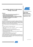
1 Introduction
Wireless Sensor Networks (WSN) have become a low power, low cost means for
communicating data between sensor devices dispersed over an area. Many of
these applications call for small embedded wireless networking solutions to
substantially reduce the cost of all required components. Atmel®’s Route Under
MAC (RUM) with support for IPv6 and 6LoWPAN is a highly flexible stack solution
for these low cost applications. Providing Internet Protocol (IP) over low power, low
data rate wireless transceivers enables immediate interoperability with existing
wired networks. With an IPv6 foundation, each wireless node on the network can
be given a worldwide unique IPv6 address and directly communicate with any other
IPv6 device in the world without the need for any translation or a complex gateway.
Free to Atmel customers, the Atmel RUM/6LoWPAN networking stack proves to be
a ready and cost-effective solution for Wireless Sensor Networks.
Rev. 8240B-AVR-06/09
2 Stack Architecture
Route Under Mac (RUM) is a small 802.15.4 protocol developed by Atmel. This
protocol routes packets at the MAC layer, as opposed to the application or IPv6 layer,
which would be a route over scheme. The under comes from the fact that routing is
done at a low level. This has a number of advantages:
•
Routers and end nodes can be simpler, and therefore less expensive. These
nodes manage almost no routing information.
•
The coordinator knows all pertinent information about every node in its PAN,
which means special “guessing” routing algorithms are not needed.
•
Higher level code does not have to be concerned with routing, and has only
to send a packet to a destination address.
The main components of the stack include RUM, and IPv6 / 6LoWPAN. The complete
stack features the following highlights:
•
Small object size. A minimal build, with only RUM and a tiny example
application, is about 6KB for an AVR end node.
•
Self-forming network. Nodes power up, find a network, and associate to it.
•
Self-healing network. Nodes re-associate upon a failure to communicate.
•
Multi-hop routing. Nodes can be multiple hops away from the coordinator.
•
Source Code Included. Free for use and free to modify if used with Atmel
hardware.
•
Designed to be a base platform for customer applications.
•
Very configurable, with the ability to add or remove features at compile time.
Features include 6LoWPAN frames, end node sleeping, and a terminal mode.
•
Portable to almost any Atmel processor.
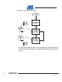
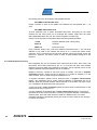
Figure 2-1 RUM Architecture
2
AVR2070
8240B-AVR-06/09
AVR2070
2.1 Overview of RUM
A RUM network is constructed around a coordinator. The coordinator is the only node
that keeps any state information about the network, so that the other nodes do not
have to store any network information. This allows for low cost hardware for both
routers and end-nodes which comprise the bulk of the network. A router can act as a
multi-hop intermediary for other nodes, while an end node can attach to a network,
but cannot associate child nodes. Any node is usable as a data node or actuator.
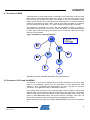
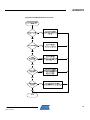
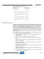
The network is organized as a tree, with the coordinator having a number of
associated nodes as children, and router nodes having their own associated children
as well. Each node has exactly one parent, which is also the node's link to every
other part of the network.
Figure 2-2 RUM Tree Topology Example
Appendix A contains a detailed description of the RUM protocol.
2.2 Overview of IPv6 and 6LoWPAN
The features of IPv6 and 6LoWPAN allow the RUM coordinator to act as an edge
router in the worldwide network. The full functionality of these features are best
utilized on the AT91SAM7X-EK development kit which provides an Ethernet
connection. This application setup is described in section 4.
Any wireless node connected to the coordinator/edge router will obtain a unique IPv6
address based on its RUM short address. Depending on the application, the wireless
node can then report sensor data directly to the coordinator/edge router, some other
server or IPv6 addressable device via the IPv6 internet connection. This node can
also receive commands when necessary based on application software.
More details about the interaction between RUM/6LoWPAN can be found in Appendix
C.
3
8240B-AVR-06/09
2.3 Supported Hardware Platforms
The RUM software distributed with this application note can run on a variety of
platforms. The PLATFORM keyword defines several parameters about a board. An
example of these parameters is:
•
Which microcontroller is present on the platform board?
•
How the microcontroller is connected to the transceiver – which radio pins
connect to which port pins on the microcontroller.
•
Any ADC connections to the microcontroller.
•
Any LED and switch connections to the microcontroller.
•
Which band the board uses – 2.4GHz, 928MHz, 868MHz or 783MHz.
See the documentation included with the source code for implementation details.
2.3.1 AT91SAM7X-EK
The Atmel AT91SAM7X-EK evaluation kit can be purchased from a local Atmel
distributor. This evaluation kit embeds an AT91SAM7X256 microcontroller which
contains an Ethernet peripheral. By obtaining any of the AT86RF2xx transceivers, the
platform can be assembled to operate as a RUM coordinator and/or IPv6 edge router.
This platform is further discussed in section 4.
2.3.2 Raven
The ATAVRRZRAVEN is the official development kit for the AT86RF230. The kit
contains two Raven boards (with LCD and joystick interface), and one Raven USB
stick.
The Raven platform has two microcontrollers – one for the radio and one for the
Raven user interface. The RUM software lives in the ATmega1284P microcontroller,
and the user interface software – supplied with RUM – lives in the ATmega3290P
microcontroller.
The user interface is not required – RUM can work as a coordinator, router, or end
node without a user interface on the Raven.
To debug RUM on Raven, two miniature 10-pin headers (supplied with RZRAVEN)
must be soldered to the board so that the programming tool can be plugged in. The
JTAGICE mkII and AVRISP programming tools can each program the Raven board.
The batteries on Raven are not sufficient to run continuously while debugging, so an
external 3V supply is recommended. Two AAA batteries make a suitable supply for
debugging if no bench supply is available.
The two processors communicate to each other using serial ports. There is an extra
serial port on the ATmega1284P microcontroller that is dedicated to the DEBUG
function. However, external wires must be added to access this port, and the signal
levels are at low logic levels, not the high voltage levels required to drive a computer's
serial port.
More information about the Raven board can be found in application note AVR2016.
4
AVR2070
8240B-AVR-06/09
AVR2070
2.3.3 Raven USB
This is the USB stick that comes with the ATAVRRZRAVEN kit. This board has an
AT90USB1287 microcontroller, which includes a built-in USB interface. Building for
the RAVENUSB platform includes the driver code for the CDC-USB interface.
The Raven USB board requires that a miniature 10-pin header (supplied with
RZRAVEN) must be soldered in for connection to the JTAG debugging port. The
JTAGICE MKII programmer will program the Raven USB board. There is not an ISP
programming header available on the USB stick.
The Raven USB stick can work as a coordinator, router, end node or sniffer with a
CDC-USB interface.
More information about the Raven USB board can be found in application notes
AVR2002 and AVR2016.
2.3.4 ZigBit / ZigBit900
These two platforms are small radio modules containing a radio (either AT86RF230
for the ZigBitTM, or an AT86RF212 for the ZigBit900) and an ATmega1281V
microcontroller.
5
8240B-AVR-06/09
3 AVR RUM Quickstart
In order to operate the RUM demo application, make sure one of the platforms
described in this document has been selected, or that a custom platform has been
properly defined in the hal_avr.h file. Also the use of an Atmel JTAGICE mkII or
AVRISP programmer will be required to program the target microcontroller.
After the target platforms and the programming tools required have been gathered,
setup the software necessary for development. For Windows® users, AVR Studio®
along with the free WinAVR tool chain can be used and downloaded free from
www.atmel.com and www.sourceforge.net. For Linux® users, the tools have to be
installed and run individually.
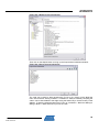
3.1 Source Code
The RUM source code that accompanies this Application Note is spread out over
several directories. The core RUM files are located in the \rum_src directory, and all
of the other directories support the uTasker operating system, which is only used with
the SAM7X version of RUM.
For AVR nodes, only the \rum_src directory is needed.
3.2 Compiling RUM
RUM has been written to work with the AVR version of the GCC compiler. AVR
Studio will compile and debug the RUM software. Alternatively for Linux, a RUM
application can be compiled and debugged using avr-gcc and other free tools.
Within the \rum_src directory, there are three AVR Studio project files that will compile
for the appropriate device of choice. There is also a Makefile that can be used with
command line tools as well. These projects have all been pre-configured with default
compile flags described in the table 3-1 below.
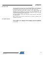
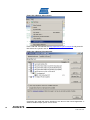
3.2.1 Compile-time Options
Rum is a very configurable protocol stack. Using a few compile-time flags, RUM can
be configured to run in a minimal amount of flash (less than 6K), or it can be
configured to that handle 6LoWPAN packets, serve data on a periodic basis, and
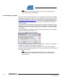
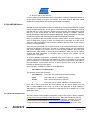
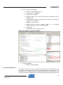
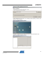
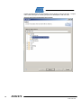
sleeps between readings. In AVR Studio, the compile-time flags described in table 31 are entered into the Project Options dialog box. This process is shown in figures 3-1
and 3-2.
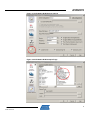
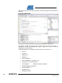
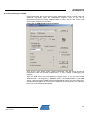
Note:
In order to compile a small flash image size for an End Node device,
the linker needs to be configured to remove any standard libraries like
printf and floating point libraries. AVR Studio linker options can be
found in the Custom Options tab of the Project options as shown in
figure 3-2. The [Linker Options] selection is located in the file list of the
left window pane. Linux users can adjust the Makefile to remove these
libraries from the command line.
6
AVR2070
8240B-AVR-06/09
AVR2070
Figure 3-1 AVR Studio RUM Project Options
Figure 3-2 AVR Studio RUM Compile Flags
7
8240B-AVR-06/09
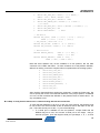
For command line operation using avr-gcc, options should be passed on the
command line as define (-D) options, such as:
avr-gcc -mmcu=atmega1281 -DF_CPU=8000000UL -DPLATFORM=RAVEN -o radio.o
radio.c (etc.)
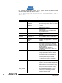
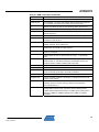
Here is a list of available compile-time flags:
Table 3-1 Compile Time Flags
Option Name
8
Possible values
Meaning
PLATFORM
RAVEN
RAVENUSB
ZIGBIT9
ZIGBIT24
Build RUM to work with the given platform.
This option can set other options, such as the
band the radio operates in (700/800/900MHz
or 2.4GHz).
Note: Not required for the ARM version of
RUM. Set PLATFORM to 0.
COORDNODE
Undefined or 1
Set this variable to cause the node to be a
coordinator node.
Note: The ARM version of RUM assumes
only a coordinator node.
ROUTERNODE
Undefined or 1
Set this variable to cause the node to be a
router node.
ENDNODE
Undefined or 1
Set this variable to cause the node to be an
end node.
APP
0 (No application)
SENSOR
IPSO
Compiles in (or leaves out) the sensor
application. New applications can be added
to the list.
DEBUG
0
1
When DEBUG is set to 1, debugging
messages can be sent out the debug port.
Also, a simple terminal interface is available
in debugging mode (Not all platforms support
this with hardware).
Note: The definition of SERIAL or
OTA_DEBUG must be used in order to use
the DEBUG flag.
DEMO
0
1
In demo mode, a node joining the network
chooses to associate to the node with the
best signal (RSSI). This allows
demonstrating multi-hop functionality in a
small area. In non-demo mode, a new node
chooses its parent based on (in order):
1. Best LQI (Link Quality Indication)
2. Lowest number of hops to coordinator
3. Best RSSI.
RUMSLEEP
0
1
Sleep mode enables the ENDNODE to sleep.
If the sensor app (APP=SENSOR) is also
compiled in, then the node will sleep between
consecutive sensor readings.
Note: Coordinators and routers do not sleep,
but the RUMSLEEP flag includes code to
wake up end nodes and put them to sleep.
WDOG_SLEEP
0
1
Setups the Watchdog timer to act as the
timing source for the sleeping operation.
Note: If set to 0, sleeping relies on an
external 32.768KHz crystal.
AVR2070
8240B-AVR-06/09
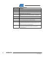
AVR2070
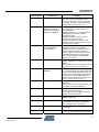
Option Name
Possible values
Meaning
IPV6LOWPAN
0
1
Compiles in 6LoWPAN functionality, which
gives each node in the network a worldunique IPV6 address, and formats packets
according to RFC4944. Without this option,
smaller RUM-only frames are used.
SENSOR_TYPE
0 (None)
SENSOR_RANDOM_T
SENSOR_RANDOM_H
SENSOR_THERMIST
Configures the sensor application
(APP=SENSOR) to collect data from the
given sensor type.
SENSOR_RANDOM_T/_H uses a random
number generator to create variable
temp/humidity data.
SENSOR_THERMIST reads a simple
thermistor from the AVR's ADC.
Note: Not all platforms support this with
hardware. SENSOR_TYPE does not apply to
the ARM version of RUM.
PAN_CHANNEL
1-4 (700MHz)
0-10 (800/900Mhz)
11-26 (2.4GHz)
Sets the operating channel to a static channel
if specified. Leaving PAN_CHANNEL
undefined will cause a coordinator node to
scan all channels to select a quiet free
channel, and will cause router/end nodes to
scan all channels to find a network to join.
Note: If CHINA_MODE=1, then 700MHz
channels are enabled.
PAN_ID
0x0000 - 0xFFFF
Sets a static PAN_ID for the specified
network. Otherwise a random PAN_ID will be
selected.
Note: A static PAN_ID is required for the IPv6
addresses in the demo. See Appendix C.
BAND
BAND2400
BAND900
The BAND flag specifies which radio band to
use. For AVR targets, this parameter is fixed
for each PLATFORM to its correct value, and
should not be directly passed to the compiler
as a parameter. For the ARM target, this
parameter can be passed as a compile-time
option, or directly set in hal_arm.h.
CHINA_MODE
0
1
Sets the use of 700MHz operation for the
China band.
Note: This mode is only available when using
the AT86RF212 (BAND=BAND900).
DATA_RATE_212
BPSK-40
Can be changed to any of the supported
operating modes of the RF212.
Note: If using CHINA_MODE, the selected
data rate is O-QPSK RC 250.
CAL
0
1
Enables the calibration feature with the
SENSOR application.
VLP
0
1
This will allow a Very Low Power device to
sleep between frame protocol operations
(scan, associate, etc) to save power.
SERIAL
0
1
Used with DEBUG to send debug messages
to a serial port.
OTA_DEBUG
0
1
Used with DEBUG to send debug messages
over the air to the coordinator for processing.
9
8240B-AVR-06/09
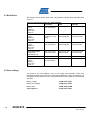
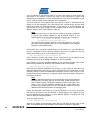
3.3 Build Sizes
This section shows various build sizes using different compile flags described from
Table 3-1.
Table 3-2 Various Build Sizes for AVR and ARM
Coordinator
Router
End Node
Raven USB Coordinator
IPv6 off
DEBUG on
Sensor App
SLEEP on
25332 bytes FLASH
4811 bytes SRAM
Raven - all features
IPv6 on
DEBUG off
Sensor App
SLEEP on
(Cannot build IPv6
coordinator on AVR
target)
21138 bytes FLASH 19280 bytes FLASH
1901 bytes SRAM
1356 bytes SRAM
Raven without Ipv6
IPv6 off
DEBUG off
Sensor App
SLEEP on
13354 bytes FLASH
2377 bytes SRAM
15218 bytes Flash
1093 bytes SRAM
13208 bytes FLASH
548 bytes SRAM
Raven Minimal Size
All options off
RUM network only
8864 bytes FLASH
1875 bytes SRAM
7984 bytes FLASH
568 bytes SRAM
5716 bytes FLASH
412 bytes SRAM
SAM7X Coordinator
IPv6 on
DEBUG on
Sensor App
SLEEP on
102K bytes FLASH
17K bytes SRAM
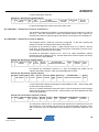
3.4 Fuse settings
The fuses for the AVR platforms vary on the target microcontroller. These fuse
settings have been listed below for the appropriate platforms. These fuse settings can
be entered into the target of choice using AVR Studio or AVR Dude for command line
operation.
10
Raven (1284p):
0xFE; 0x91; 0xE2
Raven LCD (3290p):
0xFE; 0x91; 0xE2
Raven USB:
0xFB; 0x99; 0xDE
ZigBit/ZigBit900:
0xFE; 0x91; 0xE2
AVR2070
8240B-AVR-06/09
AVR2070
4 AT91SAM7X-EK RUM Quickstart
The Atmel RUM protocol is integrated to run on the AT91SAM7X-EK board which
contains an AT91SAM7X256 microcontroller. Additionally, the IPv6/6LoWPAN layers
can be compiled in. Compiling in the IPv6 layer will allow the SAM7X platform to act
as an IPv6 Edge Router in addition to an 802.15.4 PAN Coordinator. Furthermore, the
SAM7X platform supports all the Atmel 802.15.4 transceivers: AT86RF230,
AT86RF231 and AT86RF212.
The PAN Coordinator performs the classical functions defined in section 5.3 of the
IEEE 802.15.4-2006 specification. It will start and maintain a non-beaconing network.
The edge router functionality will route IPv6 network traffic to the appropriate end and
router nodes based on their specific IPv6 addresses. The RUM protocol
implementation differs slightly from the IEEE 802.15.4 standard. Please have a look
at the documentation of the Route Under MAC (RUM) Protocol described in Appendix
A.
The SAM7X provides multiple interfaces for users to interact with the 802.15.4
wireless network. Among these are RS232, USB, telnet and simple direct web
interface. The remainder of this section will describe the implementation of low level
drivers, radio drivers, timers, uTasker RTOS integration and web interfaces.
4.1 uTasker RTOS
To jump start development and provide a solid foundation for ARM operation, the
uTasker RTOS was chosen to build upon. uTasker is not a pre-emptive type RTOS,
rather it is a task-event-state driven type. A task was created called RUM Task that is
responsible for processing radio events as well as timer events associated with the
radio protocol. For a complete description of the uTasker RTOS visit
www.utasker.com.
In addition to RUM, IPv6, and 6LoWPAN, a FAT file system has been integrated into
the uTasker system. For more details see www.efsl.be and the Doxygen
documentation. RUM and IPv6 are described accordingly within this document.
Most of the RUM application code to interact with the uTasker RTOS is located in:
•
rumtask.[c/h]
•
arm_app.[c/h]
Most of the RUM stack shares the same code base between the SAM7X and the
AVR microcontroller platforms. There are, however, specific files that only pertain to
the ARM build or the AVR build. Low level files specific to the SAM7X build are:
•
arm_timer.[c/h]
•
arm_timer_event.[c/h]
•
hal_arm.[c/h]
Additional modifications are:
•
Enabling a telnet and a user menu interface.
•
IPv6 and 6LoWPAN
•
The EFSL FAT file system
See section 3.3 for specific build size of uTasker and RUM compiled for the SAM7X.
11
8240B-AVR-06/09
4.1.1 uTasker Patches
Since uTasker is a licensed RTOS, only a binary image has been provided for
demonstration purposes. If access to the uTasker source code is required, a license
can be acquired via www.utasker.com. uTasker offers excellent licensing programs at
no or minimal cost.
With a license to uTasker, the source code can be patched to implement the RUM
architecture. These modifications add support for the RUM system and user
interaction. For instance, a user interface or menu system allows the user to change
the operating channel and other radio values. The code modifications can be found in
these files:
Application Level:
•
application.c
•
application.h
•
config.h
•
TaskConfig.h
•
app_hw_sam7x.h
•
debug.c
•
webInterface.c
•
types.h
Stack Level:
•
Tty_drv.c
•
driver.h
•
Ethernet.c
•
ppp.c
Since uTasker is provided in source code form, patch files have been produced for all
modifications needed to implement RUM with uTasker. To implement the patch files
the following procedure should be followed.
1. Download and Install WinAVR from www.sourceforge.net which provides the
patch.exe program needed to patch the uTasker project with RUM source.
2. Open the uTasker OS source code package (only available with a uTasker
license from www.utasker.com).
3. Be sure to download uTasker SP4 and apply the service pack to the original
uTasker OS source files. (Explained on uTasker website - simple copy and
replace files to apply service pack)
4. After the service pack has been installed, locate the upatch.bat and utaskerpatch files in the \patch folder within the source download package.
5. Copy these files to the same directory containing the uTasker OS with SP4
(eg. C:\project\... should contain these two files plus uTasker directory).
6. Using Windows Explorer, double click the .bat file to patch the uTasker
source for use with RUM. Note: Only run this patch procedure once.
12
AVR2070
8240B-AVR-06/09
AVR2070
This project should now include the original uTasker OS, SP4, and RUM patch files. A
test compile can now be tried using the IDE of choice. Appendix D explains two
common IDE’s that can be configured to compile uTasker with RUM support.
4.2 Radio Interface
The radio interface is composed of two parts - hardware and firmware. The hardware
is generally a radio board with physical connections to a microcontroller with the
firmware to manage the interface between the two.
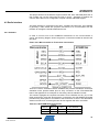
4.2.1 Hardware
In order to connect one of the AT86RF2xx transceivers to the microcontroller of
choice, the following diagram shows the generic connections needed to interface the
two parts.
Figure 4-2-1 Microcontroller to Transceiver Connections
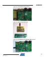
There are various evaluation boards available that provide standalone transceiver
evaluation which provide header pins for easy connection to the AT91SAM7X-EK
board. See Appendix E for examples of connecting various evaluation boards.
This section highlights the required connections for the SAM7X and any one of the
three transceivers. Using the above generic connections, the AT91SAM7X-EK board
provides many GPIO pins for connection of the transceiver of choice. The table below
shows one method of connecting the two devices together with SPI1 and GPIO.
Table 4-2-1 AT91SAM7X-EK Connections
TRX Pin
MISO
SAM7X
MCU Pin
56
Port
PA24
Port Function
SPI1_MISO
MOSI
55
PA23
SPI1_MOSI
13
8240B-AVR-06/09
TRX Pin
SCK
SAM7X
MCU Pin
50
Port
PA22
Port Function
SPI1_SPCK
SEL
49
PA21
SPI1_NPCS0
IRQ
80
PA30
IRQ0
CLKM
70
PB24
TIOB0
SLEEP_TR
13
PA8
PA8
RST
14
PA9
PA9
4.2.2 Firmware
The low level driver code is located in two files:
hal_arm.c
hal_arm.h
These files initialize SPI-1 and the discreet IO. Additionally, these files implement
handler functions that the remainder of the code uses to interact with the radio. For
instance, radio interaction is accomplished through functions such as
hal_frame_read and hal_frame_write
for receiving and transmitting a frame over the air. Other functions such as
hal_register_read and hal_register_write
allow access to radio control registers. Please refer to the detailed documentation
produced as a result of the integrated Doxygen comments in each source file. The
radio registers are fully described in the files at86rf212_registermap.h and
at86rf23x_registermap.h.
4.3 Serial Interfaces
By default, none of the serial interfaces are enabled. Possible serial interfaces are
USB and RS232. (There are two RS232 COM ports on the SAM7X board.) The telnet
interface provides more than adequate user capabilities without the hassle of
configuring a serial interface such as Hyperterminal.
uTasker provides built in serial IO capabilities for RS232 and USB. To enable serial
IO for terminal interaction by the user the following defines can be enabled in
config.h:
#define USB_INTERFACE
#define SERIAL_INTERFACE
The baud rate parameters for the RS232 port are:
•
19,200 BAUD
•
8N1
To use the USB connection on a PC running Microsoft Windows, a Windows USB
driver must be installed. This USB driver is titled uTaskerAtmelVirtualCOM.inf and
can
be
downloaded
from
the
uTasker
website
site
at
www.utasker.com/software/softwareV1.3.html and complete documentation can be
found at www.utasker.com/docs/uTasker/uTaskerV1.3_USB_Demo.PDF. However,
14
AVR2070
8240B-AVR-06/09
AVR2070
the source code and precompiled code have USB disabled. Due to limitations on the
SAM7X board, if a reset is necessary, the USB cable must be removed and any open
USB terminal sessions closed and then the board can be reconnected and the USB
terminal session restarted.
4.4 Network Interfaces
uTasker also supports a telnet interface through the RJ45 network connector. The
telnet interface is nearly identical to the serial interface. It offers the same menu
selections and utilizes the default IP address of 192.168.1.125. This address can be
changed with the “I” menu selection. The network interface also provides the
connection for the on board simple web server.
Figure 4-4-1 shows an example menu interface. The complete menu commands are
fully described in Table 5-1.
To access the telnet interface, the RJ45 cable can be connected directly to the PC's
network interface card or to a hub/router.
Note:
If connecting a PC directly to the SAM7X, the Network Interface Card
(NIC) on the computer will need to be configured to communicate on
the same IP subnet as the SAM7X.
To start the telnet session simply type “telnet 192.168.1.125” at the DOS prompt and
press enter. Alternately, on a Linux machine, type “telnet -e / 192.168.1.125” at the
terminal prompt and press enter. The “-e /” defines the escape character. Once the
telnet session is started, type “/” and a telnet prompt will appear “telnet>”. Type “mode
line” and press enter twice to return to the SAM7X telnet session. The “mode line”
command forces the Linux telnet session to echo characters typed by the user to the
telnet screen.
Figure 4-4-1. Main Menu
4.5 AT91SAM-ICE
The ARM® is programmed via the AT91SAM-ICE JTAG adapter, see the web site:
www.atmel.com/dyn/products/tools_card.asp?tool_id=3892 for more information on
this device. For Linux based systems the CrossConnect JTAG device is
recommended, see the web site: www.rowley.co.uk/arm/CrossConnect.htm for more
information on this device.
15
8240B-AVR-06/09
Note:
The SAM-ICETM JTAG adapter does not work for Linux based systems
running the Rowley Crossworks IDE.
4.6 Loading the Program
In order to load the uTasker RUM demo, the AT91SAM-ICE comes with a SAM-BA®
programmer GUI interface. This needs to be installed on the local PC that is directly
connected to SAM-ICE JTAG device. The software can also be downloaded from
www.segger.com/download_jlink.html. Various methods to program the AT91SAM7XEK target have been explained in Appendix D, but his method only describes the
SAM-BA method.
The SAM-ICE JTAG should first be connected to the USB port of the local PC. This
USB driver can be found with the SAM-BA download package. Provided the SAMBBA package has been extracted to the local PC, the USB driver should be installed
automatically.
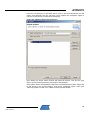
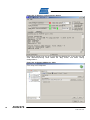
Once the SAM-BA v2.8 program has been successfully installed, open the program
and see the image shown in figure 4-6-1.
Figure 4-6-1 SAM-BA Opening Message
This pop-up window allows the selection of the SAM-ICE JTAG device connected to
the local PC. Click the “Connect” button to continue.
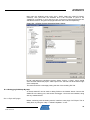
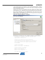
The next screen allows for the uTasker RUM demo .bin image to be selected for
programming into the AT91SAM7X256. The .bin file can be found in the \bin folder of
the source code package.
Note:
The FLASH tab is selected as the image needs to be loaded into the
flash location of the AT91SAM7X256. Be sure the FLASH address is
set to 0x100000.
16
AVR2070
8240B-AVR-06/09
AVR2070
Figure 4-6-2 SAM-BA File Selection
Once the image has been selected in the “Send File Name” field, connect the SAMICE JTAG unit to the AT91SAM7X-EK development board. Power on the target and
press the “Send File” button.
The programmer will begin communication with the AT91SAM7X-EK board and a lock
region message should pop-up shown in figure 4-6-3.
Figure 4-6-3 SAM-BA Lock Regions
Simply select the “No” button to begin programming. Upon completion of
programming the target, the SAM-BA interface can be closed which will disconnect
the SAM-ICE JTAG programmer from the AT91SAM7X-EK board causing a RESET.
The uTasker RUM demo should initialize and begin flashing the DS1 LED on board
the evaluation kit at a rate of ~ twice per second.
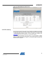
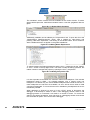
4.7 Simple Web Interface
In order to connect to the simple web interface, the webpages must first be loaded
into the SAM7X via FTP. In the source code package, locate the \web_pages folder
and notice the simple webpage files. If running Windows, open and run the
Copy_all.bat file to initiate the FTP transfer. This can be manually done for command
line operation.
17
8240B-AVR-06/09
Once the webpages are transferred, the default IP address of 192.168.1.125 must be
entered into the selected internet browser of choice to show the main webserver
page.
The simple web interface provides a quick and easy method for allowing the user to
find IPv6 address of the edge router (SAM7X) as well as the IPv6 addresses of the
connected nodes (provided the devices had code compiled with IPV6LOWPAN=1).
Additionally, a node can be pinged via its short address. Simply enter the
hexadecimal address into the ping address box and click the ping button.
Figures 4-7-1 and 4-7-2 show both pages of the simple web interface.
Figure 4-7-1 Simple Webserver Main Page
18
AVR2070
8240B-AVR-06/09
AVR2070
Figure 4-7-2 Simple Webserver Network Table
4.8 SD File Handling
The maximum size of SD card is 2 GB. The card should be formatted as FAT32. Note
that the SD file handling is rudimentary. Users needing more advanced file handling
can adapt the system as source code is available. See the files in the directory path
“../utasker/Applications/uTaskerV1.3/efsl/”. This file system was adapted from
www.efsl.be please refer to the originators for comprehensive details.
For the RUM demo described in the next section, it is recommended to initialize
(reset) the SAM7X with the SD card inserted. This will allow the EFSL to properly
initialize the data logging feature. In Table 5-1, the SD card handling commands are
described to demo operation.
19
8240B-AVR-06/09
5 Running the RUM Demo
Now that all the platforms have been properly configured with RUM, operating the
RUM demo without IPv6 is described in this section. It is assumed there is only one
PAN Coordinator per network and the PAN Coordinator can be either the
AT91SAM7X-EK board with radio interface, or another small AVR 8-bit based
platform described in section 2 (see Appendix E for third-party platforms).
Note:
If an AVR based platform is selected, there is no Ethernet interface
directly supported, just the optional serial interface. Therefore, any
Telnet and Webserver communication will not be available for network
control.
5.1 Operation
A PAN Coordinator will start a network by first locating a clear channel to begin
operations on. The PAN Coordinator will select a random PAN_ID, unless a static one
has been defined during compile time, and will begin accepting association requests
from router and end nodes. This mechanism is very similar to that described in
section 5.3 of the IEEE 802.15.4-2006 specification.
5.1.1 Network Formation
The network formed by the RUM protocol is a non-beaconing network. After the PAN
Coordinator has selected a channel to operate on, other nodes can begin to join the
network. The PAN Coordinator will issue beacons in response to beacon requests.
When a node wishes to join the network, it will send an association request to the
PAN Coordinator and the PAN Coordinator will respond with an association response.
From this, the node will retrieve its own short address. For more details about the
RUM protocol, see Appendix A.
5.1.2 Application Interface
The typical user interface to a running system with the SAM7X is the telnet menu
described in table 5-1. If an AVR platform is used as the PAN Coordinator, a different
menu is available via a serial interface described in table 5-2. The simple web server
will show a simple network table and allow the user to ping a specific node.
In order to communicate with the SAM7X telnet menu via the default IP address, see
section 4.4 for a description on how to configure the SAM7X and the local PC.
5.1.3 Main Menu
The telnet and serial menu selections are meant to be self descriptive however a
more detailed description is offered here.
Note:
Many of these are only available with the compile flag APP=SENSOR.
Also, for the ARM some of these require the compile flag
IPV6LOWPAN=1.
20
AVR2070
8240B-AVR-06/09
AVR2070
Table 5-1 ARM Telnet Menu Commands
ASCII Command
Description
a (lowercase)
IP Address. This is the current IPv4 address of the SAM7X.
A (uppercase)
IPv6 Address. This is the IPv6 address that has been self configured
or configured as a result of connecting to a true IPv6 router.
b
Break. This allows the user to stop collecting data to the SD card.
c (lowercase)
Channel. This allows the user to change the operating channel.
C (uppercase)
Calibrate. Allows the user to calibrate the end node both single and
double set points.
d
Dump. This shows the current content of the radio control registers.
f
Filename. This allows the user to set a new file name for data
collection on the SD card.
i (lowercase)
Info. This provides a quick display of current radio settings including,
PANID, Channel, Short Address, etc.
I (uppercase i)
New IP address. This allows the user to set a new IPv4 address. Once
entered the old one will no longer respond.
l (lowercase L)
Log. This will resume data collection to the SD card. It is the corollary
to the “b” command.
n
Name. Allows the user to set the name of a node – 11 characters
max.
o
Toggle node readings. Nodes report sensor readings on a periodic
basis (if APP=1). This allows readings to be displayed as they are
received. Does not affect collecting data to SD card.
p
Ping. Ping a user selected node.
Q
Quit. Quit the telnet session.
r
Read interval. Allows the user to alter the interval at which the end or
router nodes will report data to the PAN Coordinator.
t (lowercase)
Table. Display a table of nodes and their relationships.
T (uppercase)
Touch. Provides a method to either ping or change the interval of all
nodes on the network.
w
Wake. If a node has been loaded with code that allows sleep
(SLEEP=1) then it must be woken up before it can respond to
commands such as “r”.
X
Max power. The PAN Coordinator is set to transmit at the lowest
power setting in demo mode. This turns up the transmit power to
+3dBm for the RF230 and the RF231. The Max power setting for the
RF212 is +8dBm for 900MHz operation and +5dBm for 700MHz
operation.
21
8240B-AVR-06/09
Table 5-2 AVR Serial Menu Commands
22
ASCII Command
Description
T
Touch. Ping or send a Reading (asks for ‘p’ or ‘r’ & interval time).
c
Channel. This allows the user to change the operating channel.
d
Dump. This shows the current content of the radio control registers.
i
Info. This provides a quick display of current radio settings including,
PANID, Channel, Short Address, etc.
n
Name. Allows the user to set the name of a node – 11 characters
max.
p (lowercase)
Ping. Ping a user selected node.
P (uppercase)
Pause. Pause or un-pause serial display (stop serial input).
r
Read interval. Allows the user to alter the interval at which the end or
router nodes will report data to the PAN Coordinator.
t
Table. Display a table of nodes and their relationships.
s
Stream Mode. This will stream ASCII data between any two nodes in
the network provided each device has a serial connection to a host
PC.
Note: This only works for AVR based devices
w
Wake. If a node has been loaded with code that allows sleep
(SLEEP=1) then it must be woken up before it can respond to
commands such as “r”.
AVR2070
8240B-AVR-06/09
AVR2070
6 Running the IPv6 Demo
This demo requires the AT91SAM7X-EK to be used as the PAN Coordinator, due to
the Ethernet interface available on the board. The demo is separated into four parts.
The first is the ‘ping’ demo which simply verifies IPv6 network connectivity. The next
is the ‘UDP’ demo which demonstrates remote control of a node. The example sensor
application used in section 5 will then be run on IPv6. Finally a TFTP client will be
used to load new code onto an end node using IPv6. In these simple demos sleeping
will be disabled. Enabling sleep modes will be discussed later.
Familiarity of using the RUM network is required to fully understand these demos. In
particular the demo in section 5 should have been followed, verifying the webserver
on the coordinator (SAM7X) board can be reached.
In the 6LoWPAN world, the board which connects the 802.15.4 low-power wireless
network to the real IPv6 network, be it either Ethernet or WiFi, is called the “edge
router”. It lives at the edge of the 6LoWPAN network and connects it to the other IPv6
network. In this network the edge router is the PAN coordinator, or SAM7X board.
This demo may be used with full IPv6 internet connectivity if available. This is not
required to access the nodes from the local network; it is only required to access the
nodes from outside the local network.
The PAN coordinator board and AVR boards must be compiled with 6LoWPAN
support enabled. This is set by defining the IPV6LOWPAN macro to ‘1’ at build time
on both the ARM and AVR.
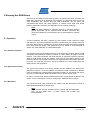
6.1 Computer/Network Setup
The demo will require IPv6 support on the host computer. If using Windows XP, type
the following at a command prompt to enable IPv6 support:
ipv6 install
If using Windows Vista®, or any Linux distribution with a kernel 2.24.0 or newer, IPv6
is already supported and enabled.
User interface and debug capabilities are provided through the telnet interface
described in section 4.4.
6.2 Ping Demo
Power the coordinator on, with the AVR nodes off. Navigate to the IPv4 address of
the webserver on the SAM7X board, and view the Network Table. There the IPv6
addresses for each interface will be shown. The board obtains the IPv6 prefix for the
Ethernet interface from another IPv6 router if one is detected. If no router is detected,
the hard-coded default prefix of 2001:db8:1e1:0::/64 is used and the board advertises
itself as the default router.
Note
Since this device becomes the default router, ALL IPv6 traffic on the
IPv6 network may be sent to it. However the device cannot actually
route this traffic, as it only has a connection to the 6LoWPAN network.
If only the 6LoWPAN network is being accessed this is fine; however, if
other IPv6 connectivity is requested this will break the network. To
avoid this, the SAM7X does NOT advertise itself as a default router
when another IPv6 router is detected on the network.
23
8240B-AVR-06/09
If an IP address for the Ethernet side is not seen, this means an IPv6 router was
discovered on the network. However the router is NOT advertising a prefix using
stateless auto configuration. Router advertisements must either be disabled on the
router, or set the router to allow stateless auto configuration.
The IPv6 prefix for the 6LoWPAN side (aka: 802.15.4 radio) is obtained from the
setting on the first webpage. The prefix always has a 64-bit length, and the AVR
nodes will acquire this prefix automatically. It may take up to 30 seconds after the
board boots for the IPv6 address of the 6LoWPAN side to show up. Refresh the
Network Table to check if the address is valid yet.
Note
If another IPv6 router is on the network, it must be manually configured
to forward any packets destined for the 6LoWPAN network to the
SAM7X board. On a Linux-based router the command to run would be:
ip -6 route add 2001:db8:1e1:1::/64 via
2001:db8:1e1:0:1af0:9fff:fee5:18f2
This will forward any traffic destined to the 2001:db8:1e1:1::/64 prefix
(the RUM IPv6 6LoWPAN prefix) to the IPv6 address of the ethernet
interface on the SAM7X board.
Connectivity of the coordinator board should now be tested. At a command prompt,
ping the coordinator board’s Ethernet address, where the IP address is the one
printed on the debug port or on the website. For example:
ping6 2001:db8:1e1:0:1af0:9fff:fee5:18f2
There should be several ping replies. If not, double-check the IP address of the
Ethernet port printed in the debug message or on the IPv4 website.
Next, attempt to ping the 6LoWPAN address of the coordinator board. This proves
that the local computer will be able to see wireless nodes. For example:
ping6 2001:db8:1e1:1:e789:ff:fe00:0
Note that the 6LoWPAN addresses may change on every reboot of the board. The
addresses are based on the PAN_ID, which can either be set to a fixed value or set to
randomly change. If fixed IPv6 addresses are desired, set the macro PAN_ID to the
desired PAN_ID when building. For example setting PAN_ID=0xe789 would give an
IP address like above.
Note
If pinging the Ethernet interface is successful but pinging the 6LoWPAN
interface fails, most likely there is an IPv6 router on the network which
has not been properly configured to forward packets to the edge router
board. A rule must be manually inserted into the routing tables that
forwards any packets destined for the 6LoWPAN network to the IPv6
address of the Ethernet interface on the edge router.
Finally, the association and pinging of a node can be tested. To do so turn on a node,
and check it associates in the IPv4 website. It should appear in the network list, and
its IPv6 address will also appear. If no IPv6 address appears, most likely the node
does not have IPv6 support enabled.
Then try to ping the node:
ping6 2001:db8:1e1:1:baad:ff:fe00:1
Several ping replies should be seen, along with an LED blink for each ping on the
node. This validates that the 6LoWPAN / IPv6 network is working as expected.
24
AVR2070
8240B-AVR-06/09
AVR2070
6.3 Using the 6LoWPAN / IPv6 Code on End Nodes
The 6LoWPAN / IPv6 API is documented using the Doxygen documentation system.
What follows is an overview of how the example application works, and is not the full
API documentation. Refer to Appendix C for the entire API documentation.
The code is designed primarily to pass data around using the UDP protocol. The user
application can send data to any arbitrary IP address, or the user can respond to an
incoming UDP packet.
A user function is called when a UDP packet is received by the node. The user is told
the source port, the destination port, the pointer to memory where the payload is
stored, and the size of the payload. To send data back to the device, the user simply
replaces the payload with what they wish to send, and returns how much data they
have placed in the payload. The stack will automatically send this message back to
the source IP address, with the destination and source ports swapped. Since most
UDP-based protocols function this way, implementation is made quick and easy.
If more control is required, functions to create an arbitrary UDP packet are provided.
Also provided are functions for generating ICMP echo requests destined to any
arbitrary address. The stack will automatically respond to any incoming echo requests
with an echo response.
6.4 IPSO App Example
The IPSO App demo showcases a wireless sensor reporting system. It uses UDP and
allows simple control of end nodes. Running the demo will require the 'netcat6'
program, which should come with most Linux distributions. This can be checked by
attempting to run the 'nc6' command.
To run the demo, the AVR devices must be built with APP set to ‘IPSO’ in addition to
IPv6 being enabled. The ping demo should still work, and provides a good sanity
check.
Note:
To communicate with other IPv6 nodes outside the local network, a
native IPv6 connection, or IPv6 tunnel end point, is required. A tunnel
can be created by using a tunnel broker such as Hurricane Electric
(www.he.net).
Windows users can find copies of netcat6.exe available online at www.sphinxsoft.com/tools/index.html.
Netcat6 is used to simply send and receive raw packets; in this case it is being used
for UDP. By typing any ASCII character and pressing enter results in a UDP packet
being sent with whatever was typed as the payload. For example, if a user typed
'hello' and pressed enter, then netcat6 will send a UDP packet with the payload as 6
bytes: 0x68, 0x65, 0x65, 0x6C, 0x6F, 0x0A. This is ASCII for "hello" followed by a
new-line. If the node responds by sending “Hi There” in ASCII, that will be printed
back to the first node.
This allows simple communication with a node without the need for special software.
Communication with a node operates like a wireless serial port. The only difference is
the node is physically located across the world, and not connected to a local
computer with a wire.
25
8240B-AVR-06/09
The IPSO demo has two parts to it. The first part is an interactive control to allow
polling of the sensor and configuration tasks. The second part is to have the sensor
automatically send data to a central server.
The wireless sensor node listens on three UDP ports, their use is as follows:
Table 6-4-1. UDP Ports
Port
Description
61616
The sensor will listen for requests on this port
61617
The sensor will listen for data from other nodes on this port
61618
The sensor will listen for administrative commands on this port
Tip
If both the destination and source ports are in the range 0xF0B0 to
0xF0BF (61616 – 61631), 6LoWPAN can compress the destination and
source ports, saving four bytes of transmitted data.
The acceptable commands on each port are listed in the next sections.
6.4.1 Commands on Port 61616
The node will accept the following commands on port 61616, and all commands must
end with either a line-feed, or carriage-return line-feed combination (<LF> or
<CR><LF>).
Table 6-4-2. UDP Commands on Port 61616
Command
Description
T
Get the current temperature. Return value will be 'T22.5' for example for a
22.5 C temperature.
H
Get the current humidity. Return value will be 'H13' for example for 13%
humidity.
L
Get the current light reading, from 0-100. Return value would be 'H50' for
example.
A
Get the status of the LED. Either 'A0' to indicate LED is off, or 'A1' to
indicate LED is on.
A1
Turn the LED on. No return value.
A0
Turn the LED off. No return value.
Unknown commands will result in a return value of the byte 0xFF followed by the
unknown command.
As an example connect to the node with netcat6 on port 61616. For these examples
<enter> means to press enter, and anything that is underlined is a response back
from the node.
C:\> nc6 -u 2001:db8:1e1:1:baad:ff:fe00:1 61616 <enter>
T<enter>
T22.5
H<enter>
H50
26
AVR2070
8240B-AVR-06/09
AVR2070
A<enter>
A0
A1<enter>
A<enter>
A1
HTL<enter>
H50T22.5L50
A0A<enter>
A0
This also demonstrates how multiple commands could be sent at once. The sensor
always sends its packets back to the source port specified in the original packet.
Note
If a response is not received, try sending either the 'A1' or 'A0'
command to turn on and off the LED. If the LED responds, the node is
receiving the message, but the response is not being passed back.
Running Wireshark on the interface may provide some useful
information, such as if the UDP response packet has an incorrect
checksum.
6.4.2 Commands on Port 61618
This is the administrative port, and allows control of various settings in the device.
The commands which can be sent are shown in the following table, and must also
end with either a <LF> or <CR><LF> combination.
Table 6-4-3. UDP Commands on Port 61618
Command
Description
S2001:0db8:01e1:0000:459D:00ff:fe29:bcf5
Set the server IP address to
2001:db8:1e1::459d:ff:fe29:bcf5
Ds
Set the destination IP of the button press to
the server address (aka: what was stored with
'S')
D2001:0db8:01e1:0001:baad:00ff:fe00:0002
Set the destination IP of the button press to
the IP 2001:db8:1e1:1:baad:ff:fe00:2
BST22.5
Send the string 'T22.5' to the IP specified with
'D' when the button is pressed.
BP
Send an ICMP echo request (ping) to the
node specified with 'D' when the button is
pressed
H
Remotely simulate a button press
G
Get the last message received by this node,
typically in response to the action occurring on
the button press.
C
Clear the last message received by this node.
All commands except for 'G' will be acknowledged with an 'OK' from the wireless
sensor.
27
8240B-AVR-06/09
When setting an IP address, the full IP address must be specified with all zeros
present. If the address is short any bytes, the node will respond “length error”.
The 'server address' is the IP address which the node automatically sends readings
to. The 'button press address' is the IP address which the node sends a certain
message to only when the button is pressed.
The 'G' command returns a timestamp in front of the last received message. This
timestamp is in milliseconds, and is a 16-bit value. Hence there will be a range of 0 –
65536, after which point the timestamp will overflow back to zero.
As a simple first example, a wireless node will be setup to ping the connected
computer.
This
assumes
the
computer's
IPv6
address
is
2001:db8:1e1::459d:ff:fe29:bcf5.
C:\> nc6 -u 2001:db8:1e1:1:baad:ff:fe00:1 61618 <enter>
D2001:0db8:01e1:0000:459d:00ff:fe29:bcf5 <enter>
OK
BP <Enter>
OK
H <enter>
OK
G <enter>
[10293] Ping took 13 mS
Note that when the 'H' command is issued, this is no different from just hitting the
button on the node.
Next let's assume there was another node on the network, and the first node wanted
to query the temperature on the second node. The following commands would cause
the first node to send the 'T' command to the second node whenever the button is
pressed. The 'G' command is then used to receive the data the second node sent the
first.
C:\> nc6 -u 2001:db8:1e1:1:baad:ff:fe00:1 61618 <enter>
D2001:0db8:01e1:0001:baad:00ff:fe00:0002 <enter>
OK
BST <Enter>
OK
H <enter>
OK
G <enter>
[12313] T22.3
6.5 Sensor App Example
The RUM example described in section 5 uses the RUM networking layer to pass
messages around. This allows end nodes to communicate with the coordinator to
exchange sensor readings, calibration data, etc. With IPv6 support enabled however,
these messages can then be passed along an IPv6 link instead.
28
AVR2070
8240B-AVR-06/09
AVR2070
By passing the messages over an IPv6 link, it does not matter if the sensors
communicate directly with the coordinator or with some other computer. As well
multiple sensor networks could report to a single coordinator device, even if that
coordinator is physically located far away from the other networks. The
communication is done using UDP, with a port-number of 61619.
To run this demo, simply compile the AVR end-nodes with APP set to ‘SENSOR’ and
IPv6 enabled. To the end-user it should work exactly the same as the demo in section
5.
The current release of the code always sends the periodic data to the coordinator.
This is set up in the sixlowpan_sensorSendPer() function, where the line:
sixlowpan_hc01_udp_setup_iplocal(DEFAULT_COORD_ADDR);
This could be changed to send to a global IP address instead. Currently any incoming
data will have a response sent to the source IP address, be on-link or not.
6.6 TFTP Bootloading
The IPv6 example also includes the ability to reload the device’s code over the air.
Note that this only works when less than half of the FLASH is used – the AVR uses
half the FLASH to temporarily store the binary. Once the entire binary is received, it
then copies the binary from the upper half of FLASH to the lower half.
This effectively limits the bootloading operations to devices with the ATmega1281 or
ATmega1284 parts, such as the ZigBit or RZRAVEN.
To use this feature, use any TFTP client that supports both IPv6 and the Blocksize
option (RFC2348). ‘TFTP Turbo’ version 4.2 or later supports both of these, and is
available at http://corporate.weird-solutions.com/products/tftp-turbo for both Linux and
Windows.
Since this 6LoWPAN layer does not support fragmentation, it is important to limit
packet size. For this reason the block size must be specified as 64 bytes. In addition,
the file name to load should be as short as possible since the file name will be
transmitted. If a long path is included in the file name, this may also be transmitted
and cause the message to not be passed over the 802.15.4 network.
The default AVR makefile will generate a file with the .noboot.bin suffix. This file has
the bootloader code removed, since that section cannot be reprogrammed. This also
saves some space, since the entire memory does not need to be transferred.
Assuming the binary is either copied to the TFTP Turbo directory, or the TFTP Turbo
directory is in the PATH, the following could be run to bootload the node
2003:db8:1e1:1:baad:ff:fe00:1 with the ENDrum.noboot.bin file:
tftpcc -p --blksize 64 2001:db8:1e1:1:baad:ff:fe00:1
ENDrum.noboot.bin
There may be messages about incorrect ACKs or timeouts. However if the transfer
completes, the file was successfully transferred to the AVR end-node. It will
automatically reflash the contents of the AVR after receiving the last packet, and then
reset the AVR.
If sleeping is enabled, the node will be forced awake during the TFTP bootloading
process. This ensures the transfer occurs at the maximum available speed. If the
node has Very Low Power (VLP) enabled however, the node is not forced awake as it
may have insufficient power for a constant wake. Instead the sleep cycle is changed
to a much faster rate – the current code changes to a 200 mS sleep cycle. This allows
bootloading to occur at an acceptable rate while still keeping a lower average power
draw.
29
8240B-AVR-06/09
6.7 Sleeping Nodes
A node that spends much its time asleep is good for battery life, but makes IP
connectivity harder. If a node only wakes up every 5 minutes, attempting to ping the
node will either fail or have a very long latency. The 6LoWPAN sleeping system
contains an extension of the RUM sleeping system. The RUM sleep system provides
a method to buffer some packets to a sleeping node. The RUM sleep system will
buffer packets if memory is available, but does not guarantee a message will be
delivered to a sleeping node. The 6LoWPAN sleep system extends this to guarantee
buffering of a special ‘wake’ command to an end node.
To communicate with a sleeping node, simply send messages to that node. When the
node awakes the message should be delivered to it, provided sufficient memory was
available to buffer the request. Since a node has a message delivered to it
immediately when it awakes, it does not need to spend much time awake and hence
saves considerable power.
A node can also be forced awake. To use this simply send the ‘w’ character to port
61618. This specific request is stored by the edge router. When the node awakes the
original ‘w’ message it passed on to the end node. This transmits to the end node the
IP address and UDP source port of the requesting computer. The end node will
process the ‘w’ message, announcing to requesting computer it is now awake. The
current code sends back the string ‘awake’ to the requesting computer. The node will
then stay awake for a configurable timeout period where the default is seven
seconds. If no activity is detected in seven seconds, the node goes back to sleep.
Both the timeout period and the node polling interval are configurable. A short timeout
and long polling interval means the node is spending the minimum amount of time
awake, and will have the best battery consumption.
The time between the node waking up and checking if it has new data is the
‘SIXLOWPAN_PERIODIC_TIME’ variable. The time is defined in tenths of a second,
th
and has a minimum value of 1/10 of a second. For example the following would set
a 2-second period:
SIXLOWPAN_PERIODIC_TIME = 20;
The amount of time the node waits before going back to sleep is set by the
SIXLOWPAN_TIMEOUT_MS define. This is a value in mS, and has a minimum value
of 50 mS and a maximum of 65000 mS. This is defined as a constant in
sixlowpan_wake.h:
#define SIXLOWPAN_TIMEOUT_MS 7000
Additionally an application callback is provided. This will be called after a certain
number of SIXLOWPAN_PERIODIC_TIME, and can be used to send periodic sensor
readings for example. If this variable is set to ‘0’ the feature is disabled.
SIXLOWPAN_PERIODIC_APP_TIME = 15;
When using the SENSORS app with IPv6, the periodic app timer is set to a constant
of ‘1’. The periodic time is a user-configurable variable, hence every time the node
wakes up the periodic data is sent. This variable is set using the 'r' command
described in section 5.
In normal 6LoWPAN applications the SIXLOWPAN_PERIODIC_TIME and
SIXLOWPAN_PERIODIC_APP_TIME are set in the sixlowpan_application_init()
function. They can also be changed at run-time, for instance to switch to shorter sleep
intervals during certain times of the day when power is abundant.
30
AVR2070
8240B-AVR-06/09
AVR2070
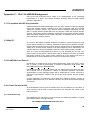
Appendix A - Route Under MAC (RUM) Protocol
A.1 Overview
This appendix outlines the scheme used by RUM for implementing a route-under
network, where the routing of network packets is done at the MAC layer. This has a
number of advantages:
•
Routers and end nodes can be simpler, and therefore less expensive. These
nodes manage almost no routing information.
•
The coordinator knows all pertinent information about every node in its PAN,
which means special “guessing” routing algorithms are not needed.
•
Higher level code does not have to be concerned with routing, and has only
to send a packet to a destination address.
•
Auto-forming network
•
Auto-healing network (re-associates when a broken link is detected)
•
Multi-hop routing of data at the MAC layer
•
PING packets are defined and implemented at the MAC layer
•
Small (~6K) flash code size for end nodes and routers.
•
Packets conform to 802.15.4 spec.
A.2 Features
A.3 Assumptions
Here are the assumptions about the end application that have led to the design of this
networking scheme:
1. End nodes and routers are small, low-cost devices. The single coordinator is
larger and more capable. Therefore, each end nodes stores only two short
addresses – its own address and the address of its parent.
2. Routers store a table of directly-connected (children) end nodes and router
nodes.
3. The end nodes are usually sleeping to save power. Coordinator and router
devices are powered all the time. Routers could be configured to be off most
of the time, with a configured time slot for synchronized operation. Support
for sleeping routers may require an extension to the protocol.
4. The coordinator, routers, and end nodes will auto-form a working network,
and packets can be routed to/from any node to any other in the network using
only the short address as the destination.
5. Each node can be accessed from outside the PAN via the coordinator.
6. All data packets must be routed through the coordinator.
7. The network is self-healing, so that a broken connection causes a re-forming
of network connections. The re-connection is handled at the application
layer, so that the parameters for detecting and re-establishing a broken
network can be tuned to the application’s performance requirements and
environment.
31
8240B-AVR-06/09
8. Some pre-deployment configuration can be used to determine whether a
given node should or can join a given network. This configuration is part of
the application, not the MAC.
9. Only short (16-bit) 802.15.4 addresses are used in sending data over the
network except during association, since a new node does not have a short
address until it is issued one.
10. The coordinator's short address is defined to be 0x0000.
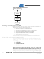
A.4 Implementation Details
A.4.1 End node
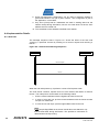
The message sequence chart in Figure A-4-1 shows the effect of the end node
“scanning” a particular channel by sending out a beacon request and receiving a
beacon.
Figure A-4-1 Channel Scan Message Sequence
End/Router Node
Pan Coord/Router Node
Beacon Request
Beacon
When the end node powers up, it performs a scan to find a parent node.
The node sends a beacon request frame on each channel and listens for beacon
frames. The node picks a router based on the following criteria:
1. Pick the router/coordinator with the highest LQI value for the link.
2. In event of a tie with LQI, pick the router/coordinator with the lowest number
of hops to a coordinator.
3. In event of a tie with hops, pick the highest RSSI value for the link.
Note:
If the compile flag DEMO is set, these criteria above are altered to only
find the best RSSI during association. This provides a mechanism to
demonstrate multi-hop routing.
32
AVR2070
8240B-AVR-06/09
AVR2070
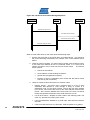
Figure A-4-2 Direct Association Message Sequence
End/Router Node
Pan Coord Node
Association Request
Association Response
The node then associates to its parent as illustrated in figure A-4-2 (above):
The node sends an Association Request packet to the chosen router (or coordinator).
The association request payload includes the MAC address of the end node, the
short address of the parent router node, and the type of the requesting node (router
or end). This request is forwarded to the coordinator, and the coordinator issues a
response, which is routed back to the new node.
The node receives an Association Response packet from the router (originating from
the coordinator). The newly associated node then stores the two short addresses
contained in the association response – its own short address and parent's short
address.
When the node becomes associated, it must only store a few bits of information to be
connected to the network.
•
Its own short address (16 bits).
•
The short address of its parent (16 bits).
•
The PAN ID of the network (16 bits).
•
The channel of the network (8 bits).
The node sends data to coordinator periodically per the application, via the parent
router (or coordinator if the node is directly connected to the coordinator).
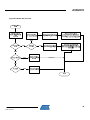
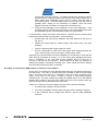
A.4.2 Router node
The router node can act as an intermediary between end nodes and the rest of the
network. It can either be directly associated with the coordinator, or indirectly through
a chain of router nodes. The direct scenario has been illustrated in figures A-4-1 and
A-4-2 and the indirect scenario is illustrated in figure A-4-3. A router node can also
perform the duties of an end node, sending data readings as the application requires.
33
8240B-AVR-06/09
Figure A-4-3 In-Direct Association Message Sequence
End/Router Node
Router Node
Pan Coord Node
Association Request Direct
Association Request Indirect
Association Response Indirect
Association Response Direct
When a router node starts up, the router does the following steps:
1. Perform the steps that an end node does, as outlined above. This results in
the router becoming associated to the network, with a short address and a
parent.
2. Listen for beacon requests. For each beacon request, issue a beacon frame.
If the router has reached its limit of router/end nodes, or if it has lost its
network connection, then it does not return a beacon frame.
The beacon
frame contains:
•
PAN ID of the network.
•
Short address of node sending the beacon.
•
Special ID byte (application specific).
•
Number of hops to coordinator (zero means that the beacon frame
was sent by the coordinator).
3. Listen for frames received from parent or children nodes.
34
•
Routing frames – this frame has a payload which is a list of short
addresses that describe a route through a string of routers to a
destination node. For this kind of frame, remove the first short address
from the list, and re-send the frame to the short address removed from
the list. Also, store the address of the next router in the chain, so that all
further data packets will be sent to this child node from now on.
•
For all other frames – dispatch to other nodes in the following order. The
word “my” denotes the router’s point of view.
•
If the final destination address is my child node, then send the packet to
the child.
•
If the frame was sent from my child node, send the packet to my parent.
AVR2070
8240B-AVR-06/09
AVR2070
•
If neither of the above conditions apply, then send the packet to the last
routed address used for sending (which was stored from a routing frame).
4. If an association response is received with the router's short address as
parent, then add the child node to a table of child nodes and short addresses,
and forward the association response to the new child node.
5. Listen for frames received from non-parent nodes – both end nodes and
other routers. Forward all frames to parent. This includes association
request frames. Note that a router can only receive frames that are explicitly
sent to its short address and PAN ID.
A.4.3 Coordinator node
The coordinator keeps track of every node in the PAN, including the route needed to
reach a given node. With each association request/response transaction, the
coordinator builds a table that contains information on each node in the network:
Table A-4-1. Coordinator network table
Short Address
Type
MAC address
2-byte address
issued by
coordinator at
association
End node or
router node
The unique 8byte 802.15.4
address
Parent Short Addr
IPv6
Address
The short address of
Node’s
the parent of the given IPV6
node.
address
Last
Route
Sleeping
Short addr Flag: is the
of last
node
node
sleeping?
routed
•
The short address of a node is really the index into the table of the node, so
that the address is not explicitly stored.
•
The node Type is either end (3) or router (2). The coordinator is Type (1).
•
The “Last Route” entry in the table is only used for a node that is a router
directly connected to the coordinator. This entry contains the short address
of the last destination node routed to that router's tree. This is useful for
sending a data packet to a node in the tree without having to re-send a
routing packet. The coordinator figures out which router to use to send a
routing packet, and if the destination node is the same as “Last Route”, then
no routing packet is necessary.
When the coordinator starts, it performs the following actions:
1. Do a scan to find any existing networks, and scan for RF energy at the same
time. Pick a free and clear channel and randomly choose a PAN ID. Or,
alternatively, pick a pre-defined channel and PAN ID if PAN_CHANNEL
and/or PAN_ID compiler variables are set.
2. Listen for beacon request packets from other nodes. Same as step 2 of router
node.
3. For each association request, store the new node's information in the network
table shown in Table A-4. Then send an association response back to the
new node.
4. To send a packet to a child node, a routing packet may be required. Note
that a routing packet is only required under certain circumstances:
35
8240B-AVR-06/09
•
The destination node must be more than two hops away from the
coordinator. For one or two hops, there is no ambiguity in the route, so
no routing packet is required.
•
The last time a packet was sent through the top-most router in a sub-tree,
the destination address was different from the address of the packet
currently being sent.
5. To create a routing packet, the coordinator builds a list of short addresses for
each node in the chain to get to the destination node. The coordinator then
sends the routing packet to the first router node in the chain. This causes
each router in the chain to remember the route for the following data
packet(s). The list does not include the destination short address, since the
last router in the chain will recognize the data packet's final destination
address as the address of one of its own children, and will send the packet on
without any explicit routing information.
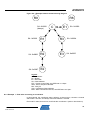
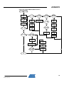
A.5 Examples of network operation
For the following examples, see Figure A-5-1. Note that IEEE 802.15.4 headers are
variable-length, with some fields omitted depending on the value of the various fields
within the FCF.
36
AVR2070
8240B-AVR-06/09
AVR2070
Figure A-5-1 Example Network Commissioning Diagram
R9
R8
SA: 0x0000
(always)
C
E1
R1
R3
SA: 0x0006
R2
E3
SA: 0x0007
E2
SA: 0x0003
SA: 0x0002
SA: 0x0004
SA: 0x0005
Legend:
C = coordinator
Rn = Router
En = End node
SA = Short address
FCF - Frame Control Field, see IEEE 802.15.4 Spec.
SEQ - Frame Sequence Number
PID - PAN_ID
CSA - Coordinator Short Address
MAC - MAC Command Frame ID, see IEEE 802.15.4 Spec.
A.5.1 Example 1 – End node connecting to coordinator
In this example, the coordinator starts, performs a channel scan, chooses a channel
and PANID = 0x1234, and always uses short address = 0x0000.
End node E1 starts, does a scan, and finds the coordinator C (and no other beacon).
37
8240B-AVR-06/09
Table A-5-1. Beacon request and beacon frames
E1 FCF – beacon req Seq Broadcast PAN ID
0x0803
01
0xffff
C
FCF – beacon
0x8000
Seq
PID
01 0x1234
Broadcast short addr
0xffff
Coord SA
0x0000
Superframe
0x40ff
07 (beacon req)
0x07
ID (6=6LoWPAN)
0x06
Hops
0
E1 selects C based on zero hops, and sends association request. The payload
contains E1's MAC address, and the SA of the parent. This is called a “direct
association request” because the source address is a long (MAC) address and the
frame was sent directly from the associating node.
Table A-5-2. Association request frame (direct)
E1 FCF –assoc req Seq
PID
C SA
E1 MAC addr
0xC863
02 0x1234 0x0000 0x1122334455667788
MAC
01
Parent SA
0x0000
Type
0x03
C assigns E1 to its table of nodes, and sends an association response. This is a
“direct association response” because the destination address is a long address, so
that the frame is sent directly to the newly-associated node.
Table A-5-3. Association response frame (direct)
C FCF – assoc rsp Seq
PID
E1 MAC
0x8C63
03 0x1234 0x1122334455667788
Coord SA
0x0000
MAC Cmd
02
E1 SA
0x0002
E1 stores two addresses: its own newly-acquired short address, and the short
address of its parent.. In this case the parent is the coordinator C.
E1 sends data to coordinator C as needed.
Table A-5-4. Data packet to coordinator
E1 FCF – data Seq
PID
Coord SA
0x8861
04 0x1234
0x0000
E1 SA
0x0002
Final
Dest SA
0x0000
Origin
SA
0x0002
Frame
Type
0x01
Payload
per
application
A.5.2 Example 2 – Router R1 connects to Coordinator C
Coordinator C has started and has chosen PANID = 0x1234, and short address =
0x0000
Router node R1 starts, does a scan, and finds the coordinator C (and receives no
other beacons).
Table A-5-5. Beacon request and beacon frames
R1 FCF – beacon req Seq Broadcast PAN ID
0x0803
01
0xffff
C
FCF – beacon
0x8000
Seq
PID
01 0x1234
Coord SA
0x0000
Broadcast short addr
0xffff
Superframe
0x40ff
07 (beacon req)
0x07
ID (6=6LoWPAN)
0x06
Hops
0
R1 selects C as it is the only available network, and sends an association request.
Table A-5-6. Association request (direct)
R1 FCF –assoc req Seq
PID
C SA
0xC863
02 0x1234 0x0000
38
R1 MAC addr
0x3333444455556666
MAC
01
Parent SA
0x0000
Type
0x02
AVR2070
8240B-AVR-06/09
AVR2070
C sends association response.
Table A-5-7. Associaton response (direct)
C FCF – assoc rsp Seq
PID
E1 MAC
0x8C63
03 0x1234 0x3333444455556666
Coord SA
0x0000
MAC Cmd
02
R1 SA
0x0003
R1 stores two addresses: Parent (coord) SA and R1 SA.
A.5.3 Example 3 – Router R3 connects to Coordinator C
This example is identical to example 2, except that R3 receives a beacon from R1 as
well as C. Since the coordinator C node is accessible directly to R3, it ignores R1,
because the number of hops are higher than directly connecting to the coordinator C.
A.5.4 Example 4 – Router R2 connects to Network
This example shows a multi-hop node being configured. At the start, assume that
routers R1 and R3 are already associated to the network.
R2 powers up, and scans for routers. It gets a beacon from C, R1, and R3. Since C
is far away, its LQI is less than R1's LQI, so R2 ignores C and tries to connect to R1,
since its signal is stronger than R3's signal.
R2 sends an association request to R1. This is an “direct association request”
because the source address is long. All new nodes send a direct request, since they
do not yet have a short address.
Table A-5-8. Association request (direct)
R2 FCF –assoc req Seq
PID
R1 SA
0xC863
01 0x1234 0x0003
R1 MAC addr
0x5555444433332222
MAC
01
Parent SA
0x0003
Type
0x02
R1 forwards the association request to C, after re-arranging the packet into an
“indirect association request”, which has both addresses as short.
Table A-5-9. Association request (indirect)
R1 FCF –assoc Seq
PID
C SA
R1 SA
req 0x8863 02 0x1234 0x0000 0x0003
MAC Par SA
CMD 0x0003
01
R2 MAC addr
0x5555444433332222
Type
0x02
C stores R2's MAC address and assigns a short address to R2. It then sends back
an association response frame.
This is an “indirect association response” frame, since the response is sent through a
router and not directly to the end node. Indirect frames use short addresses for both
source and destination.
Table A-5-10. Association response (indirect)
C FCF – assoc rsp Seq
PID
R1 SA
C SA
0x8863
03 0x1234 0x0003 0x0000
MAC
02
Parent SA
0x0003
R2 MAC ad
0x55554...
R2 SA
0x0006
R1 receives the frame from C, and notices that the Parent SA matches its own SA.
This causes R1 to re-package the frame into a “direct association response” frame,
and to store R2's SA in its child table before sending the association response on to
R2.
39
8240B-AVR-06/09
Table A-5-11. Association response (direct)
R1 FCF – assoc rsp Seq
PID
R2 MAC addr
0x8C63
03 0x1234
0x5555444433332222
R1 SA
0x0003
MAC
02
R2 SA
0x0006
R2 saves its parent's short address and its own short address.
A.5.5 Example 5 – End node E2 connects to network
This example shows an end node connecting to the network, through two routers R2
and R1.
E2 scans for routers, and selects R2 based on LQI/hops/RSSI. It then sends a direct
association request.
Table A-5-12. Association request (direct)
E2 FCF –assoc req Seq
PID
R2 SA
0xC863
05
0x1234
0x0006
E2 MAC addr
0x8877665544332211
MAC
01
Parent SA
0x0006
R2 forwards the packet to R1, converting it to an “indirect association request”.
Table A-5-13. Association request (indirect)
R2
FCF –
Seq
PID
R1 SA R2 SA
assoc req 05 0x1234 0x0003 0x0006
0x8863
MAC
01
Par SA
0x0006
E2 MAC addr
Type
0x8877665544332211 0x03
MAC
01
Par SA
0x0006
E2 MAC addr
Type
0x8877665544332211 0x03
R1 forwards the packet to C.
Table A-5-14. Association request (indirect)
R1
FCF –
Seq
PID
C SA
R1 SA
assoc req 06 0x1234 0x0000 0x0003
0x8863
C assigns E2 a short address, add E2's SA and Parent SA to its table, sends a
routing packet to E2, and then sends an association response to R1.
Table A-5-15. Association response (indirect)
C FCF – assoc rsp Seq
PID
R1 SA
C SA
0x8863
07 0x1234 0x0003 0x0000
MAC
02
Parent SA
0x0006
MAC
02
Par SA
0x0006
E2 MAC ad
0x88776...
E2 SA
0x0007
R1 forwards the packet to R2.
Table A-5-16. Association response (indirect)
R1 FCF – assoc rsp Seq
PID
R2 SA R1 SA
0x8863
08 0x1234 0x0006 0x0003
E2 MAC ad
0x88776...
E2 SA
0x0007
R2 notices that the new node's parent is R2, and sends a “direct association
response” packet to E2, and stores E2's SA in its child table.
Table A-5-17. Association response (direct)
R2 FCF – assoc rsp Seq
PID
E2 MAC addr
0x8C63
09 0x1234
0x887766...
40
R1 SA
0x0003
MAC
02
E2 SA
0x0007
AVR2070
8240B-AVR-06/09
AVR2070
A.6 Routing packets
There is a special packet used to create a route for a packet leaving the coordinator
toward any router or end node. Each router node keeps track of the last address it
sent a routing packet to, and will send each later (non-routing) packet from its parent
to the same address (unless the packet is addressed to a child node). This way, the
coordinator can send one routing packet to an end node, followed by many data
packets. Each data packet will travel the route specified by the last routing packet.
For example, suppose the router has to send a data packet to end node E2. The
router simply scans its table of nodes to find out E2's parent, then that node's parent,
and so on, constructing a router frame as shown:
Table A-6-1. Routing packet
C
FCF – routing
Seq
0x8863
22
PID
0x1234
R1 SA
0x0003
C SA
0x0000
MAC
0xbb
R2 SA
0x0006
Note that the end node's (E2) short address does not need to be in the routing
packet. As long as the data packets that follow the routing packet end up at R2, then
R2 will read the destination address in the data packet and correctly forward the
packet to E2, since E2 is a child of R2. R1 does not have to actually send an empty
routing packet to R2, since R2 does nothing with it.
Also, note that R1's short address is not in the routing packet. This is because R1 is
the first hop in the chain, and R1's address is in the frame header.
In this example, R2 is the only node whose short address is in the payload. If there
were more than one intermediate jump, then the nodes closest to the coordinator
come first in the payload.
When a node receives a routing packet, it does the following:
1. If there is more than one short address in the packet, then create a new
routing packet to the first SA in the list, and remove the first SA from the list.
2. Store the SA of the second address in the list. Until further notice (by a new
routing packet), forward any data packet addressed to a non-child node sent
downstream to this stored address.
One good feature of this routing implementation is that a routing packet only has to be
sent if the receiving node is more than two hops away from the coordinator. For
networks that occupy a physically small area, routing packets should rarely be seen.
A.6.1 Data packets
Data is sent in a data packet. Data from an end node is always relayed to the
coordinator, and downstream packets are routed in the same path as the last routing
packet.
Table A-6-2. Data frame (Coordinator C to Router R1)
C FCF – Data Seq
PID
R1 SA
C SA
0x8861
34
0x1234
0x0003 0x0000
Final Dest
SA
0x0007
Origin SA
0x0000
Data
payload
When a destination node sees its own short address in the “Dest SA” field, it accepts
the data and of course does not forward the packet.
41
8240B-AVR-06/09
Table A-6-3. End node E2 to Coordinator C via Router R2
E2
FCF –
Seq
PID
R2 SA
E2 SA
Final Dest
Data
34 0x1234 0x0006 0x0007
SA
0x8861
0x0000
Origin SA
0x0007
Data
payload
A data frame from a child node is passed to the coordinator. The source and
destination addresses in the 802.15.4 frame header are changed for each hop, but
the rest of the frame is unchanged. Final destination and origin addresses do not
change as the packet progresses through the network.
A data frame may pass through the coordinator, if the “Dest SA” field is anything but
0x0000 (coordinator's short address). Any frame the coordinator sends, whether it is
relayed through the coordinator or originates with the coordinator, is preceded by a
routing packet if necessary.
A.7 Packet Formats
There are only a few packets used in this system, so structures can be pre-defined for
each. The key values used to distinguish one frame type from another are the FCF
value and the MAC Command byte.
Note that a new MAC command byte of 0xBB has been defined for a routing packet.
This is of course non-standard; however, it is not expected that other proprietary
networks are able to route RUM packets, so nodes in another network should never
have to parse a RUM routing packet.
Table A-7-1. Pre-defined packet types
Type
42
FCF
MAC CMD
Beacon request
0x0803
7
Beacon
0x8000
-
Association Request- direct
0xC863
1
Association Request- indirect
0x8863
1
Association Response – indirect
0x8863
2
Association Response – direct
0x8C63
2
Routing packet
0x8863
0xBB
Data packet
0x8861
-
AVR2070
8240B-AVR-06/09
AVR2070
Appendix B - Firmware API Overview
This appendix discusses how the RUM firmware is implemented, what Application
Programming Interface (API) functions are present, and gives some detail about what
functions are called to implement the RUM protocol.
The firmware source, available with this Application Note, has been extensively
documented in source code comments. This documentation exists as HTML pages
which are generated from the source itself using the Doxygen program. Refer to the
Doxygen-generated documentation for a more detailed description of how the
firmware operates and complete list of API and functions.
The descriptions of software organization in this appendix apply to the AVR version of
the firmware. The SAM-7X version firmware uses a multitasking OS – µTasker – to
coordinate the various tasks, but the flowcharts below still largely apply.
B.1 Program Organization
The program is structured using a simple “forever” loop in the main() function. The
program performs some initialization, and then forever calls some task functions –
appTask() and macTask(). These two functions service events generated by interrupt
service routines (ISR’s).
Examples of ISR’s include the radio interrupt (packet
received or sent), timer interrupt, and serial port interrupt.
The main loop processing is called the foreground, and the ISR processing is called
the background.
Communication between background (ISR functions) and
foreground (main loop) is done with an event queue. The background process stores
an event in the queue with the mac_put_event() function, and the foreground pulls
events from the queue with a call to mac_get_event(). In this way ISR events can be
handled without clobbering foreground processing.
Figure B-1 shows this overall scheme.
The main() function configures the system before entering the main loop. Most of the
hardware setup is done in the appInit() function. Figure B-2 shows the major events
that occur as a result of calling appInit. A coordinator node will create a new network
with itself at the center, and a router or end node will connect itself (associate) to the
closest available network.
If the node fails to find or associate to an existing network, the scan process is started
again after a one second delay.
Figure B-3 outlines the macTask() function. This is called very often from the main
“forever” loop, and handles events that have arise from interrupt routines. There is an
event queue that stores the interrupt events in FIFO order, and macTask() retrieves
items from the queue and processes each one in the order in which the events were
received. Every event except for serial character I/O is handled by macTask().
The flowchart in Figure B-4 shows how macDataIndication() dispatches received data
frames. A “data frame” here means a frame with the Frame Control Field element
Frame Type set to type “data” per the IEEE 802.15.4 specification. Data frames
application data, ping request and response frames, drop child command frames, and
6LoWPAN frames.
Figure B-6 shows the flowchart for the radio’s interrupt service routine (ISR). The
AT86RF2xx family has one interrupt pin, so the ISR must determine what event
caused the interrupt and then dispatch the event to the appropriate routine for
processing.
43
8240B-AVR-06/09
Figure B-1 Overall Program Structure.
If a frame was received by the radio, it is transferred from the transceiver into a
receive buffer in the host processor. End-of-transmit interrupts and energy detect
interrupts are dispatched from the ISR and values stored for later processing from the
main loop.
44
AVR2070
8240B-AVR-06/09
AVR2070
Figure B-2 appInit overview
45
8240B-AVR-06/09
Figure B-3 macTask overview
46
AVR2070
8240B-AVR-06/09
AVR2070
Figure B-4 macDataIndication overview
47
8240B-AVR-06/09
Figure B-5 Frame routing overview
Routing
Start
Am I
coordinator?
Coord
Send routing
packet if
necessary
Is dest a child
of mine?
No
Resend packet to
first router in chain
Router
Yes
Is destination
my child?
Yes
Send packet to
child (destination)
Resend packet to
child (destination)
No
Is this frame
from parent?
Yes
48
No
Packet is from
child – resend to
my parent
Send to default router (see
macConfig.lastRoute)
End
AVR2070
8240B-AVR-06/09
AVR2070
Figure B-6 Radio ISR overview
49
8240B-AVR-06/09
The flowchart shown in Figure B-5 shows how the RUM protocol routes packets.
Most of this processing occurs in the macRouteData() function. The flowchart shows
that just a few simple rules are needed to route packets to their destination.
B.2 RUM API
An application talks to the MAC by using a few function calls in the MAC, and the
MAC communicates events back to the application by calling pre-defined callback
functions. The relevant MAC functions and the callback functions are listed in the
header file system.h.
B.2.1 Coordinator commands
•
macFindClearChannel() is called on startup. The new coordinator node
finds a clear channel by doing an energy scan and finding the quietest
channel. Alternatively, a pre-defined channel can be set in PAN_CHANNEL.
•
appClearChanFound() is called when the scan is complete. The coordinator
chooses a channel and PAN ID by calling macStartCoord(), and is then
ready for operation.
When the coordinator receives a beacon request, it calls sendBeaconFrame(), which
sends a beacon back to the requester.
When the coordinator receives an association request, it calls
macAssociationResponse(), which stores the new node's information in the
coordinator's network table, and issues an association response frame.
B.2.2 Router and end node commands
On the router/end node side, several functions are called in sequence associate to
the network. The timing of these calls are regulated by the MAC's timer module, by
making calls to macSetAlarm().
50
•
macInit() is called to initialize the radio and the MAC.
•
macScan() is then called to search for a network to join. This causes the
node to send out beacon request nodes on every channel, and to record the
beacons it gets back. The best node is chosen.
•
appScanConfirm() is called when the scan is complete. If the scan was
successful, then appScanConfirm calls appAssociate, which in turn calls ...
•
macAssociate() - this sends an association request to the coordinator
(sometimes via intermediate nodes), and processes an association response
packet with ...
•
appAssociateConfirm() is called when the node either associates
successfully, or times out waiting to associate.
•
After the nodes have associated the macConfig.associated flag is set to true
and, all nodes communicate using the same functions:
•
macDataRequest() is called by the sending node, or macPing() is called to
ping another node. The MAC calls back to either appPacketSendSucceed()
or appPacketSendFailed().
•
macDataIndication() is called by the MAC if a packet is received that is
addressed to this node.
AVR2070
8240B-AVR-06/09
AVR2070
For more detailed examples of association and sending sensor data, see MAC
function calls and Sensor application function calls.
There are a few other useful functions that the MAC offers. These functions are useful
for making a non-networking application, such as a remote control unit.
•
macIsChild() reports on whether a given node is a child of this node.
•
macSetOperatingChannel() can be used to manually set the radio channel.
•
radioGetPartnum() will query the Atmel transceiver and return the part
number.
•
radioGetSavedRssiValue() returns the last measured received signal
strength indication (RSSI) value for a received packet.
•
radioGetSavedLqiValue() returns the last measured link quality indication
(LQI) value for a received packet.
•
radioGetOperatingChannel()
•
radioGetTxPowerLevel() and radioSetTxPowerLevel() set and read the
output RF power levels
•
radioBatmonGetVoltageThreshold(), radioBatmonGetVoltageRange(),
radioBatmonConfigure(), and radioBatmonGetStatus() are used to work
with the RF2xx on-board battery monitor function.
•
radioGetClockSpeed() and radioSetClockSpeed() allow the use of the
RF2xx CLKM signal, which can be used to clock the CPU or provide an
accurate timebase to calibrate any other oscillator.
•
radioEnterSleepMode() puts the transceiver to sleep and
radioLeaveSleepMode() wakes up the transceiver.
•
radioSendData() sends a "raw" packet over the radio. This is a lower-level
function that RUM uses to send data to another node.
•
radioRandom() returns up to 8 bits of random data, created from the random
radio noise on the RF2xx radio. The RF230 does not have a random number
generator, so the radioRandom function only returns a random number from
the rand() system function.
•
nodeSleep() Puts the entire node to sleep for a specified time.
Other MAC parameters reside in the macConfig structure. While this structure is not
meant to be used by the application directly, several useful parameters are available
for reference:
•
longAddr - The long (MAC) address of this node
•
associated - True if this node has been associated to a network
•
panId - The PAN ID of this node
•
shortAddress - the short address of this node
•
parentShortAddress - the short address of this node's parent
•
currentChannel - the current radio channel selected
The timer module can be used by an application to execute functions after a nonblocking delay.
The Serial Port module provides a serial port for the AVR targets.
51
8240B-AVR-06/09
B.3 6LoWPAN API
This group of functions is used to send a UDP packet to a node either on the wireless
network (‘iplocal’) or somewhere outside the wireless network (‘ipglobal’). The source
and destination ports are set, the payload loaded, and finally the UDP packet is sent.
The Doxygen documentation provides specific examples.
•
uint8_t * sixlowpan_hc01_udp_setup_ipglobal(void)
•
void sixlowpan_hc01_udp_setup_iplocal(uint16_t addr)
•
void sixlowpan_hc01_udp_setup_ports(uint16_t srcport, uint16_t destport)
•
uint8_t * sixlowpan_hc01_udp_get_payloadptr(void)
•
void sixlowpan_hc01_udp_set_payloadsize(uint8_t size)
•
void sixlowpan_hc01_udp_send(void)
This function below is called on the AVR when a UDP frame is received. The UDP
payload is pointed to by payload and is of length payloadlen. After the frame is
processed, a message can be sent back to the source port and IP address by
copying a new payload into the payload pointer. The return value indicates how many
bytes to send back – a return of zero results in no response sent back. The
payloadmax parameter indicates the maximum allowable payload that could be sent.
This function is written by the user, an example is provided in the
sixlowpan_application_example.c file.
•
uint8_t sixlowpan_udp_usercall (uint16_t sourceport, uint16_t destport,
uint8_t * payload, uint8_t payloadlen, uint8_t payloadmax)
The following group of functions is used to send an ICMP Echo Request (ping) to a
remote IP address. The Doxygen documentation contains an example of how to use
this to ping an end node.
•
uint8_t * sixlowpan_hc01_ping_setup_ipglobal (uint8_t sequence)
•
void sixlowpan_hc01_ping_send (void)
The next function is called when an ICMP Echo Response is received. The sequence
holds the sequence number of the returned ping.
•
void sixlowpan_ping_usercall (uint8_t sequence)
This function below handles an incoming RUM frame that is flagged as containing
6LoWPAN data. It copies the frame to another buffer, and calls the
sixlowpan_hc01_process() function on the AVR. This function performs any needed
actions – responding to Neighbor Solicitation, storing information from Router
Advertisements, responding to Echo Requests, and calling user functions if data is
received. The 6LoWPAN and IPv6 stack on the ARM device are based on uIPv6
integrated into Contiki. See www.sics.se/contiki and the RUM source code for
integration details. This process is shown for AVR devices in figure B-7 and for ARM
devices in figure B-8.
•
52
void sixlowpan_DataIndication(ftData * frame, uint8_t payloadlen)
AVR2070
8240B-AVR-06/09
AVR2070
Figure B-7 AVR 6LoWPAN DataIndication
53
8240B-AVR-06/09
Figure B-8 ARM 6LoWPAN DataIndication
sixlowpan_DataIndication()
Start
Call 6LoWPAN
Layer to
uncompress
packet to buffer
Call IPv6 Layer on
uncompressed
packet
End
B.4 Writing a Custom Application Using RUM
RUM is meant to be a base upon which a custom application can be written for a
wireless product. There are a few steps to doing this.
•
Make sure the hardware is compatible with RUM.
•
Add a new PLATFORM definition to RUM for the new hardware.
•
Verify that the transceiver is talking to the microcontroller.
•
Verify that the RUM network is working on the hardware.
•
Add the application code to the project.
Each of these steps is covered in detail. An AVR target is assumed in this section.
B.4.1 Step 1: Make sure the hardware is compatible with RUM
To work with RUM, the design must contain an AVR or ARM processor that is
supported. As of this release, RUM has been proven to work with these
microcontrollers:
•
ATmega1281
•
ATmega1284P
•
ATmega88P, 168P, 328P
•
AT90USB1287
•
AT91SAM7X256
Almost any AVR can be made to work with RUM, as long as it includes an SPI
interface, as all of the AT86RF2xx transceivers interface with the microcontroller over
SPI. In addition to the SPI interface, the radio has an IRQ output that must be
supported as an interrupt on the AVR. This can be an external interrupt, pin change
interrupt, or timer capture interrupt. The 'RF230 has a rising edge interrupt signal,
54
AVR2070
8240B-AVR-06/09
AVR2070
and the RF231 and RF212 radios can be configured for rising or falling edge via the
IRQ_POLARITY register value.
In addition, there are some GPIO signals that must be connected to the
microcontroller:
•
RST – Reset signal, active low
•
SLP_TR – Sleep/Transmit signal. See radio datasheet for details.
•
CLKM – Optional clock output from the radio.
•
SCLK – SPI clock
•
MOSI – SPI Master Out/Slave In signal
•
MISO – SPI Master In/Slave Out signal
•
SEL – Radio select line, active low.
Note that the transceiver can operate on a supply of 1.8V to 3.6V, while the
microcontroller may have a different operating range. Be sure both devices operate
from the same supply voltage, or that the appropriate level-shifting circuitry has been
added.
On some AVR microcontrollers, the SPI interface pins used to connect to the radio
are shared with the ISP programming port. This can cause difficulty connecting to the
target processor, as the transceiver's select line can float high, causing the radio to
drive the MISO line, which interferes with ISP function. The solution to this problem is
to put a pull-up resistor on the radio SEL (select) line. If this resistor causes
excessive sleep current, it may be removed after programming the AVR.
Affected AVR microcontrollers include the ATmega88/168/328 family.
RUM currently operates with an Internal RC oscillator set for 8MHz.
B.4.2 Step 2: Define a new PLATFORM for the hardware
A platform describes several aspects of a board:
•
Which microcontroller is connected to the radio.
•
How the radio pins are connected to the microcontroller.
•
Which interrupt vector the radio uses.
•
How to enable and disable the radio's interrupt handler.
•
Which serial port the board uses for debugging I/O (optional).
•
How to enable/disable/read the ADC for sensor data (optional).
•
How to read and set buttons and LED's on the board (optional).
•
Which band the radio operates in.
Define the new platform in hal_avr.h by adding a new entry to the list of platform
types. Then define a block of parameter definitions similar to the existing platform
definitions. For example:
(In the list of platform definitions)
#define MY_NEW_BOARD 9
(further down in file)
#elif PLATFORM==MY_NEW_BOARD
// Set this to the Microcontroller the new design uses
55
8240B-AVR-06/09
#ifndef __AVR_ATmega1281__
#error "Incorrect MCU for Platform! Check Makefile"
#endif
// Set this to the port that the SEL pin is connected to
#
define SSPORT
B
// Set this to the pin
#
define SSPIN
that the SEL pin is connected to
(0x00)
// Set this to the port that the SPI port is on
#
define SPIPORT
B
// Set this to the pin that the MOSI signal is on
#
define MOSIPIN
(0x02)
// Set this to the pin that the MISO signal is on
#
define MISOPIN
(0x03)
// Set this to the pin that the SCLK signal is on
#
define SCKPIN
(0x01)
// Set this to the port that the RST pin is connected to
#
define RSTPORT
B
// Set this to the pin
#
define RSTPIN
that the RST pin is connected to
(0x05)
// Set this to the port that the SLP_TP pin is connected to
#
define SLPTRPORT
B
// Set this to the pin that the SLP_TP pin is connected to
#
define SLPTRPIN
(0x04)
// Set this to the UART number (0, 1, 2, etc.) for the
// serial port being used.
#
define USART
1
// Define which port of the AVR hosts the ADC converter.
#
define ADPORT
F
// Define which pin of the ADC port is connected
// to an analog input.
#
define ADPIN
(0x00)
// Define the DIDR register associated with the ADC pin
// (See AVR datasheet).
#
define DIDR
DIDR0
// Define which 16-bit timer is to be used for the
// system timer.
#
define TICKTIMER
3
// Define which AVR vector handles the radio interrupt.
#
define RADIO_VECT INT0_vect
// Define Macros to handle setting up interrupts and
// ADC functionality
#define HAL_ENABLE_RADIO_INTERRUPT( ) EICRA |= 3, EIMSK |= 1
#define HAL_DISABLE_RADIO_INTERRUPT( ) EICRA&=~3, EIMSK &= ~1
56
AVR2070
8240B-AVR-06/09
AVR2070
#
define HAL_INIT_ADC() DIDR0 |= (1 << ADPIN), \
ADMUX = 0xC0 | ADPIN, ADCSRA = 0x84
#
define HAL_STOP_ADC() ADCSRA &= ~0x80
#
define HAL_SAMPLE_ADC() ADCSRA |= (1 << ADSC) \
| (1<< ADIF)
#
define HAL_WAIT_ADC() while (!(ADCSRA | (1<<ADIF))) {;}
#
define HAL_READ_ADC() ADC
#
define BAND BAND900
// RF212
// LED Macros
#define LED_INIT() (DDRE |= ((1<<2) | (1<<3) | (1<<4)),\
PORTE |= ((1<<2) | (1<<3) | (1<<4)))
// LED_ON(led), where led = 1-3
#define LED_ON(led) (PORTE &= ~(1 << (led+1)))
#define LED_OFF(led) (PORTE |= 1 << (led+1))
// Button macros
#define BUTTON_SETUP()
DDRE &= ~(1 << PE5), \
PORTE |= (1 << PE5)
#define BUTTON_PRESSED() (DDRE &= ~0x20, \
PORTE |= 0x20, !(PINE & 0x20))
Note that some features may not be available on a new platform, like the ADC
converter or the LED’s and button. To leave a feature out of the platform definition,
define it as nothing, so that the compiler will not complain about the missing symbol:
#
define HAL_INIT_ADC()
#
define HAL_STOP_ADC()
#
define HAL_SAMPLE_ADC()
#
define HAL_WAIT_ADC()
#
define HAL_READ_ADC() 0
#
define BUTTON_SETUP()
#
define BUTTON_PRESSED()
#
define LED_ON()
#
define LED_OFF()
0
After checking these definitions against the schematic, compile the RUM code. Be
sure to specify the correct microcontroller definition in the project options, or Makefile
on Linux, so that it matches the definition in the platform block as shown above. Fix
any compilation errors.
B.4.3 Step 3: Verify that the transceiver is communicating with the microcontroller
To verify that the definitions in hal_avr.h or hal_arm.h are working, the firmware must
be run to see if the microcontroller is able to read and write to the radio via the SPI
port. There are two ways to do this. Try one of the following.
1. If a serial port is available on the new platform, compile RUM with the
DEBUG flag set to one, and connect a serial port to the target. Using a
terminal program, open the target's serial port (38.4Kbps, n, 8, 1, no flow
57
8240B-AVR-06/09
control) and press the enter key. A simple terminal menu should be printed,
and the ASCII 'd' character should cause a dump of the radio's register set. If
these values look reasonable (not all zero's or 0xff's), then the radio is
connected properly. If terminal display does not print, then the radio code is
probably stuck, waiting for the transceiver to initialize, which will never
happen if the radio isn't able to communicate over the SPI port.
2. Using the AVR debugger, set a breakpoint on the call to appTask(). If the
firmware is able to execute to this point, then it can be assumed that the radio
has initialized properly, and therefore the radio can communicate.
If communication cannot be verified, then there is a problem with the interconnects
between the radio and the microcontroller. Try the following:
•
Double-check the interconnect definitions that were added into hal_avr.h or
hal_arm.h.
•
Inspect the target board for solder bridges, bad solder joints, and other
problems.
•
Verify the board's power supply voltage is correct.
•
Use an oscilloscope to watch each radio signal while stepping through the
code. Does each pin move up and down as directed by code?
After basic SPI communication has been established, it is necessary to verify that the
radio interrupt mechanism is working. To do this, simply start debugging the target,
place a breakpoint on the radio ISR function (RADIO_VECT) in hal_avr.h or
hal_arm.h, and then run the program. There should be at least one interrupt on
startup (TRX_END) if everything is working right. There should also be an interrupt
when the radio receives any 802.15.4 packet.
B.4.4 Step 4: Verify that the RUM network is working on the hardware
At this point, it is important to verify that the RUM network is completely functional on
the new board. To do this, a second node will be needed to talk to the first target
board. This other node must be a coordinator if the new node is configured as a
router or end node, or vice versa. If there is a telnet or serial debug interface
available and it has been enabled by setting the DEBUG flag to one, the DEBUG
interface will be able to show when the nodes connect as soon as both nodes are
powered on (and running firmware) at the same time.
If there is no network connection between the two nodes, check the following:
1. Are both nodes working in the same band?
2. If the band is 900MHz, are both radios using the same modulation scheme?
3. Is the coordinator set to a single fixed channel? See the PAN_CHANNEL
keyword.
58
AVR2070
8240B-AVR-06/09
AVR2070
Appendix C - IPv6 / 6LoWPAN Background
Using IPv6 and 6LowPAN will be easier if an understanding of the underlying
technologies is in place. This section assumes familiarity with the RUM network
outlined in Appendix A.
C.1 The problem with RF-Only Networks
Atmel® provides the RUM network layer as a very easy method of passing messages
around the wireless network. Problems occur when messages need to be passed
outside the wireless network. Any wireless protocol designed specifically for the
802.15.4 radios (RUM included) will have poor support outside the physical wireless
network. This means passing messages outside the physical radio network requires
either specialized software on connected computers, or translating the RF protocol to
some well-known network protocol.
C.2 Why IP?
IP is used in the biggest computer networks in existence, proving its ability to scale
across global networks. IP is already supported by almost every desktop computer,
meaning that accessing a sensor network using IP would require no specialized tools.
Setting up a wireless sensor network could be managed by the IT department of a
company where no special knowledge outside of normal network setup is needed.
Since IP is such a general-purpose protocol, it is not optimized for low-cost, lowpower nodes. At first glance it would seem crazy to attempt to use such a versatile
high-power protocol for tiny sensor nodes. However IP is very flexible, and many of
the benefits of IP can be obtained with a minimum of resources required.
C.3 6LoWPAN to the Rescue
6LoWPAN is a working group at the Internet Engineering Task Force (IETF), which
has a number of RFC’s documenting a method of transmitting IPv6 across Low
power Wireless Personal Area Networks.
6LoWPAN specifies how the IP packets can be passed across the 802.15.4 links.
This includes how to compress IP headers to eliminate redundant information,
fragmentation to pass messages larger than a single 802.15.4 frame, and how to
guarantee interoperability between this low-power IPv6 network and the greater
internet.
A huge advantage of 6LoWPAN is that nodes from different vendors, running at
different radio frequencies or on different channels, can all be interconnected through
an IPv6 link.
C.4 A Crash Course in IPv6
An understanding of IPv6, and how it differs from IPv4 is needed to run this demo. A
quick overview is given here in order to educate a user with this new version of the
Internet Protocol.
C.4.1 IPv6 Addressing
IPv6 addresses are 128-bits long, and are written in hexadecimal notation. A typical
IPv6 address written out might look like:
2001:0DB8:0000:0000:0008:0800:200C:417A
59
8240B-AVR-06/09
Any leading zeros can be dropped, writing addresses like:
2001:DB8:0:0:8:800:200C:417A
Finally a number of zeros in the middle of the address can be replaced with '::', as
such:
2001:DB8::8:800:200C:417A
All IPv6 networks have a “prefix” associated with them. Everything on the same
network has the same prefix, so for example the network might have the prefix
2001:0DB8:0000:0000::/64. The '/64' means the prefix is 64-bits long.
Here are a few important IPv6 prefixes that have been globally allocated:
::1/128
loopback address (note 128-bit prefix)
FF00::/8
multicast
FE80::/10
link-local unicast
Every interface always has a link-local address associated with it. The link-local
address is only valid on the network the device is on, it cannot be routed across
networks. This is important as the link-local address cannot be pinged across the
internet for example. The device needs to have a global address assigned to the
interface.
C.4.2 IPv6 Neighbor Discovery
IPv6 integrates into the core protocol how nodes find each other, their router, and
information about what network they are on. In IPv4 this was done with Address
Resolution Protocol (ARP) over Ethernet for example. This is required to find out the
mapping between a physical address and an IP address.
Neighbor discovery consists of four main types of packets. The first is neighbor
solicitation packets. These are sent to discover if a certain IP address is on the
same network, and if so what the physical address of it is.
A neighbor solicitation packet will be answered with a neighbor advertisement
packet. This advertises that a certain physical address is associated with an IP
address. Note the “physical address” will be referred to as the MAC, link-layer, Layer
2, or L2 address. All these terms are synonymous.
A node can send a router solicitation packet to inquire about routers that are on the
network like shown in Figure C-4-1.
A router solicitation is answered with a router advertisement packet. This informs
the nodes about the router information including: the physical address, router lifetime,
network prefix, and if the router should be used as a default router. This router
solicitation will also be periodically sent by the router to inform nodes of any changes
in network information.
60
AVR2070
8240B-AVR-06/09
AVR2070
Figure C-4-1 IPv6 Router Discovery
C.4.3 Node Auto-configuration
On power-up a node uses these packets to acquire an address using stateless autoconfiguration. It first auto-configures a link-local address by using the fe80:: prefix
followed by an interface identifier description (IID) based on its physical address. It
then sends a neighbor solicitation packet looking for someone else with this same
address – this is the duplicate address detection (DAD) phase. If no response is
heard to the neighbor solicitation, it assumes it has a valid unique address. A router
solicitation is then sent out to learn about any on-link routers. If the routers have prefix
information, it can then combine the network prefix with the IID to form a globally
accessible address.
As an example, consider how an Ethernet interface with a physical address of
00:1C:23:2B:BD:6C gets a fully operational address:
1. Node comes to life, calculates an IID of 021c:23ff:fe2b:bd6c/64 from its
physical address.
2. Node sends a neighbor solicitation to fe80::21c:23ff:fe2b:bd6c.
3. Node waits for response, resending neighbor solicitation a certain number of
times.
4. Node fails to hear a response, so auto-configures itself to have the address
fe80::21c:23ff:fe2b:bd6c.
5. Node sends a neighbor advertisement, advertising it has address
fe80::21c:23ff:fe2b:bd6c.
6. Node sends a router solicitation.
7. Router sends a router advertisement, out of which node finds the network
prefix is 2001:db8:1e1::/64.
8. Node sends neighbor solicitation to 2001:db8:1e1:0:21c:23ff:fe2b:bd6c, again
listening for a response.
9. No response heard, node advertises
2001:db8:1e1:0:21c:23ff:fe2b:bd6c.
itself
as
owning
address
61
8240B-AVR-06/09
10. Node is now on the network.
It can be seen how IPv6 simplifies auto-configuration of network addresses. Nodes no
longer require DHCP to acquire an address. IPv6 does support DHCPv6 (called
stateful auto-configuration) should the extra features be required.
C.5 6LoWPAN Basics
Consider that the IPv6 header alone is 40 bytes long, and IPv6 specifies that a packet
may be at least 1280 bytes. At first glance it would seem crazy to attempt to combine
this with 802.15.4, who’s maximum packet size is 127 bytes. The header alone would
take 31% of the entire packet, not even including the 802.15.4 header. However
6LoWPAN bridges these two technologies seamlessly, taking advantage of a number
of features of IPv6 to transmit the packets without substantial overhead.
Many of the fields in the IPv6 header are often certain values, and do not require the
range of data which is given to them. For instance the ‘flow label’ is 20 bits, but is
often zero. Hence a single bit can be used to indicate if the ‘flow label’ is zero, and if it
is zero it is not transmitted.
The previously mentioned way in which IPv6 can auto-configure addresses based on
the physical address is also used. The 802.15.4 header already has the destination
and source address of a packet, but this is the physical address. Since the IPv6
addresses are often based on these physical addresses, there may be no need to
transmit the IPv6 addresses. In the best case a 40-byte IPv6 header can be
compressed to two bytes.
To do this address compression, 6LoWPAN relies on the notion of “context”. Here
“context” means the node knows what address or prefix to use based on the context
of the conversation. For example one of the context’s the node knows is the prefix of
the local network. There would never be a need to transmit this, since all nodes on
the network already know this prefix.
As an example, consider if a node has an IP address of:
2001:db8:1e1:1:baad:ff:fe00:1
The address can be split as follows:
2001:db8:1e1:
This is the IPv6 prefix for the network (64 bits)
baad
This is the 802.15.4 PANID (16 bits)
ff:fe00
This is a fixed bit-sequence (32 bits)
1
This is the 802.15.4 short address for the node (16-bit)
From this it can be seen how the IPv6 address can be directly written from the
802.15.4 short address of the node. To send to the node with an IPv6 address of
2001:db8:1e1:1:baad:ff:fe00:5, it means the node with the short address of 5 is the
destination node.
C.5.1 Draft-ietf-6lowpan-hc01
The exact version of the “header compression” used in this project is HC01, available
at http://tools.ietf.org/html/draft-hui-6lowpan-hc-01. Since the standard is evolving,
this is not the most recent version of the header-compression standard. The most
recent version will be available at http://tools.ietf.org/wg/6lowpan. The following
quickly describes what features are present in HC01, and supported by this code:
62
AVR2070
8240B-AVR-06/09
AVR2070
Traffic Class and Flow Label encoding
A message will be properly parsed by end-nodes regardless if traffic class and flow
label is compressed or uncompressed. However the value itself is not read, hence to
avoid wasting space all messages should have the traffic class and flow label set to
zero.
Address Compression
The code supports carrying all 128 bytes; or compressing an address down to 64, 16,
or 0 bytes of extra payload.
Next Header Compression
Only a UDP packet will have the next header field compressed, any other type will
have the next header field carried in full.
Hop Limit Compression
A hop limit of 255, 64, or 1 will result in the hop limit being compressed. Any other
value will result in the hop limit field being carried in full.
UDP Header Compression
UDP Header compression is supported by this implementation.
C.6 6LoWPAN Compressed Header
If sniffing a 6LoWPAN network, it can be useful to understand the header. Note that
the 802.15.4 payload will be the RUM frame, which includes some additional fields.
The 6LoWPAN header described here is actually the RUM payload. Table C-6-1
illustrates this relationship.
Table C-6-1 Understanding the relationship between 6LoWPAN, RUM, and 802.15.4 Frames.
802.15.4 Frame
802.15.4 Header
802.15.4 Payload
RUM Data Header
FCF
Seq
PID
0x8821
0x12 0x1234
RUM Data Payload
Dest
Src
Final
Dest
Origin
Type
6LoWPAN Frame
0x0006
0x0007
0x0000
0x0007
0x05
…..
The 6LoWPAN Frame contains three bytes of interest at the beginning. The first is the
‘dispatch’ which is always set to 0x03, which corresponds to the header compression
used. The HC01 Encoding is specified in two bytes, and a detailed description of this
field is given at http://tools.ietf.org/html/draft-ietf-6lowpan-hc-01 in section C.5.1.
Additionally the source code for the avr_sixlowpan.c file in the
sixlowpan_hc01_process() function provides a reference for decoding the
compressed 6LoWPAN header.
Table C-6-2 6LoWPAN Frame
6LoWPAN
Dispatch
HC01
Encoding
Compressed IPv6 Header / IPv6 Payload
1 byte
2 bytes
Variable
63
8240B-AVR-06/09
Compared to normal IPv6 networks, there are some differences to how a node
acquires its IPv6 address. A typical startup sequence on this Atmel 6LoWPAN
network is (shown in Figure C-4-1):
1. Node associates to coordinator using RUM protocol, and is assigned an
802.15.4 short address
2. Node sends IPv6 router solicitation to edge router (coordinator)
3. Edge router sends router advertisement back, including IPv6 prefix
4. Node stores this prefix as the default context it uses in all communication
5. Node now has an IPv6 address, since it has context and a short address
There are several differences from the normal IPv6 auto-configuration. Sending
physically multicast / broadcast messages is eliminated, as it is not necessary since
the edge router address is already known from RUM association. End nodes do not
perform duplicate address detection, as each node is guaranteed to have a unique
address on the 6LoWPAN network.
The current IPv6 stack on the end devices (AVR) has some limitations. The most
important ones are:
64
•
Incoming IPv6 checksums are not checked, however outgoing packets have
valid checksums in them.
•
The IPv6 edge router and PAN coordinator must be the same device.
•
Fragmentation is not provided at the 6LoWPAN layer, meaning packets must
fit within a single 802.15.4 frame.
•
All IPv6 addresses of nodes on the network must be based on short
addresses.
AVR2070
8240B-AVR-06/09
AVR2070
Appendix D - AT91SAM7X-EK Development Tools
uTasker can be compiled in a number of different environments: IARTM, Rowley
Crossworks and EclipseTM (with gcc). The discussion that follows here is based on the
Rowley Crossworks tool chain and the Eclipse tool chain.
D.1 Folder Structure
The complete source code for the ARM and AVR based platforms are contained in
the folder structure shown in figure D-1-1. This is the folder structure as downloaded
from www.atmel.com. The RUM specific source is located in the \rum_src folder. The
\patch folder contains the modified uTasker files to support RUM. Follow the uTasker
patch procedure described in section 4.1.1 to create the new folder structure shown in
figure D-1-3.
Figure D-1-1 RUM Source and uTasker Support Download
The original uTasker source package should have the SP4 already integrated before
applying the RUM patches. Figure D-1-2 shows the uTasker source package before
the RUM patches (a uTasker license is required for source code access from
www.utasker.com).
Figure D-1-2 uTasker Original Source w/ SP4 Package
After following the uTasker RUM patch procedure, the following folder structure
shows the integrated uTasker and RUM project for application development.
65
8240B-AVR-06/09
Figure D-1-3 uTasker and RUM Integrated Folder Structure
D.2 Rowley Crossworks IDE
Rowley Crossworks is a cross platform IDE that is lower cost alternative to other ARM
development IDE’s on the market. There are many license models available. Rowley
Crossworks and detailed documentation can be downloaded for the ARM from
www.rowley.co.uk/arm/index.htm. Following are the steps necessary to setup
Crossworks for the first time and subsequent debug sessions.
1. A 30-day Evaluation License may be requested before purchasing.
a. Open Tools -> License Manager
b. Request Eval license by email (one day processing).
2. Download Support Packages
a. Open Tools -> Download Packages From WEB
b. Download Board Support: Atmel - AT91SAM7X-EK.hzq
c.
Download CPU Support: Atmel - AT91SAM7.hzq
d. Complete installation procedures for both packages.
3. Open an existing project
a. File -> Open
b. Locate the Rowley project file for the uTasker RUM demo
(ie...\utasker\Applications\uTaskerV1.3\Rowley_SAM7X\uTaskerV13.
hzp). Need to have uTasker license to obtain source level access.
4. Install Segger J-Link software package for the AT91SAM-ICE JTAG
programmer from www.segger.com/download_jlink.html.
66
AVR2070
8240B-AVR-06/09
AVR2070
5. Load J-Link .dll for debugging
a. Target -> Connect Segger J-Link
b. Should see “DLL WARNING”
c.
Select Tools -> Targets
d. Highlight “Segger J-Link”, right-click and select “Properties” as shown
in figure D-3-1.
e. Find Properties window in lower right corner, make sure properties of
“Segger J-Link” is selected.
f.
Highlight “J-Link DLL File”
g. Locate
.dll
file
from
Segger
folder
Files/SEGGER/JLinkARM_V392/JLinkARM.dll)
(ie.
C:/Program
h. Re-do Step A.
i.
Verify Device Type Connects to J-Link
Figure D-2-1 Segger J-Link DLL Installation
6. To Start debugging
a. Debug -> Start Debugging
D.2.1 Rowley RUM Project
The Rowley project file can be launched by opening up the \patch folder and
navigating to the \Rowley RUM Project File folder containing the .hzp project file. This
file needs to be copied over the original Rowley project file located in the
\uTaskerV1.3\Rowley_SAM7X\ folder. Assuming all the project patch procedures and
67
8240B-AVR-06/09
folder structuring has been properly followed; the Rowley project file should build as
expected.
Figure D-2-2 Rowley IDE
The Rowley Crossworks interface looks like the image shown in figure D-2-2.
The Rowley compile option flags can be set via the IDE. Click on Project ->
Properties to locate the Preprocessor Options. Figure D-2-3 shows what the
configuration screen looks like.
Complete descriptions of compile time options are found in section 3.2.1:
68
•
APP=0,1
•
CHINA=0,1
•
DEBUG=0,1
•
DEMO=0,1
•
IPV6LOWPAN=0,1
•
PAN_CHANNEL=0 or integer 0 – 26
•
PAN_ID=0 or 2 byte user defined
•
PLATFORM=0
•
BAND=BAND2400, BAND900
•
CHINA_MODE=0, 1
•
RUMSLEEP=0,1
•
SENSOR_TYPE=0
Note: Not needed for SAM7X
AVR2070
8240B-AVR-06/09
AVR2070
Figure D-2-3 Rowley Project Properties
Then click on the ellipsis button to bring up the Preprocessor Definitions window.
Figure D-2-4 Pre-processor Definitions
The code can be built by either pressing the F7 key or by clicking on the Build the
menu item and then clicking on Build -> uTaskerV13. After successfully compiling the
code it can be downloaded to the target using the SAM-ICE (or CrossConnect) JTAG
adapter. To start the download press the F5 key or click Build -> Build and Debug to
debug or Build -> Build and Run to just run the code.
69
8240B-AVR-06/09
Note:
Sometimes the SAM7X will retain old FLASH values such as IP
addresses. This can be a valuable feature during code reloads to keep
static variables. To ensure that the memory is purged, the Erase jumper
on the SAM7X board can be connected to ground. Doing so will
completely erase the memory and will ensure that reloaded code will
implement new values.
D.3 Eclipse IDE
D.3.1 Required Tools
Besides the RUM source code, a few external tools are needed. These tools are the
compiler and associated toolchain, the graphical interface, the emulator interface, and
the FLASH programming tool.
D.3.1.1 YAGARTO
YAGARTO is a GCC compiler distribution. Download the latest version of the
“YAGARTO GNU ARM toolchain” from www.yagarto.de. Their website also has links
to other documentation on setting up the toolchain.
D.3.1.2 Eclipse
Eclipse is the graphical interface that will be used. Get the C/C++ Edition from
www.eclipse.org/downloads/.
D.3.1.3 J-Link Software and Documentation Pack from Segger
This provides the GDB-Server that allows the Atmel SAM-ICE to be used for
debugging.
Obtain
the
software
pack
from
Segger
at
www.segger.com/download_jlink.html.
D.3.1.4 AT91SAM-ICE (SAM-PROG)
The SAM-PROGTM utility allows programming the FLASH memory in the SAM7X
device using the Atmel SAM-ICE. Get the latest version of the “AT91-ISP.exe‟ from
www.atmel.com/dyn/products/tools.asp?family_id=605.
D.3.2 Installing
Run the provided installers for each tool. With Eclipse there is no install needed – just
extract the folder and create a shortcut to the eclipse.exe program.
D.3.3 Building RUM – Step by Step
Start the Eclipse program; a splash screen should appear.
If no splash screen appears, there may be a problem with the Java® Runtime
Environment. Check the Eclipse documentation on eclipse.org for more details.
Eclipse will then ask for the “workspace”, which is where it stores all its projects.
70
AVR2070
8240B-AVR-06/09
AVR2070
Figure D-3-1 Eclipse Workspace Selection
In this example they are stored in the f:\eclipse_projects directory. With that, the
Welcome screen will appear:
Figure D-3-2 Eclipse Welcome Screen
Clicking the “workbench” icon on the far right will then open the workbench view:
Figure D-3-3 Eclipse Workbench View
71
8240B-AVR-06/09
Finally the RUM project can be imported. This is done by going to the “File -> Import”
menu. Select the type as “Existing Projects into Workspace”, and click next:
figure D-3-4 Eclipse Import Selection Screen
72
AVR2070
8240B-AVR-06/09
AVR2070
Point the root directory to the RUM source code. It should automatically find the
project, and optionally one can check the “Copy projects into workspace” option to
copy the source files to a local Eclipse workspace.
Figure D-3-5 Eclipse Import Project Screen
Upon hitting the “Finish” button, Eclipse will import all the files. This will also copy
them to the local working directory if that option was selected.
Some paths need to be updated to reflect the local development system. Right-click
on the project in the Project Explorer, and hit the “Properties” option. Then open
“Discovery Options” under “C/C++ Build” in the Properties window.
73
8240B-AVR-06/09
Change the “compiler invocation command” to point to the YAGARTO installation. In
this example it is located at C:\Program Files\yagarto\bin\arm-elf-gcc.exe:
Figure D-3-6 uTasker Project Properties Compiler Setting
74
AVR2070
8240B-AVR-06/09
AVR2070
Next open the “Settings” pane under “C/C++ Build”. Select the “GNU Elf Parser”
checkbox, then point both the addr2line and c++filt command to point to the
YAGARTO commands. In this case this was C:\Program Files\yagarto\bin\arm-elfaddr2line.exe and C:\Program Files\yagarto\bin\arm-elf-c++filt.exe respectively.
Figure D-3-7 uTasker Project Properties Binary Parser
Hit OK, and attempt to rebuild the project. Select “Project -> Clean”, and it should
clean and then rebuild the project. View output in the “Console” tab at the bottom right
of the workspace.
The result should be a message printing the size of the resulting ELF file.
D.3.4 Debugging RUM Step-By-Step
An Atmel SAM-ICE can be used to debug RUM on the SAM7X board. Connect the
SAM-ICE to the debug port, and ensure the Segger J-Link tools are installed, along
with any needed drivers.
D.3.4.1 Zylin CDT plugin
Before continuing with the debug tutorial, install an extra plugin for Eclipse. This is
easily done, by using the “Help -> Software Updates..” menu:
75
8240B-AVR-06/09
Figure D-3-8 Eclipse Debug Plugin
Press “Add Site” and add the site http://opensource.zylin.com/zylincdt and press OK.
Now select the “zylincdt” and hit “Install”:
Figure D-3-9 Eclipse Zylincdt Install
Completing the install will require agreeing to the terms of the license agreement. If
asked to restart Eclipse, press “Yes” to do so.
76
AVR2070
8240B-AVR-06/09
AVR2070
D.3.5 Programming the FLASH
First programming the FLASH memory with SAM-PROG will be covered. With the
SAM-ICE connected, open the SAM-PROG program. Point to the file at
Applications\UTaskerV1.3\GNU_SAM7X\uTaskerV1.3.bin. Ensure the “None” and
“Auto-mode” checkbox are checked.
Figure D-3-10 SAM-PROG Flash Programmer
Then hit the “Yes” button under “Target Connected”, and the device should be
programmed. With the FLASH programmed, it is now a matter of debugging the
program.
Start the GDB server from the Windows Program menu. It can be found under
Windows Start -> All Programs -> SEGGER under “J-Link ARM V3.96b / J-Link GDB
Server”. Note that both the GDB server and SAM-PROG can be run at the same time,
provided both programs do not access the SAM-ICE at the same time. An indication
the J-Link is connected should appear:
77
8240B-AVR-06/09
Figure D-3-11 Segger J-Link Connection Screen
Next Eclipse needs to be set up to work with the GDB Server. To do this click the
small downward-pointing arrow beside the “Bug” button, and select “Debug
Configurations”:
Figure D-3-12 Eclipse GDB Server - Main
78
AVR2070
8240B-AVR-06/09
AVR2070
A new window will pop up, and select the “Zylin Embedded debug (Native)” category,
and hit the new button. Set the name, and then set the project by hitting the “Browse”
button and selecting the project.
Assuming the project has successfully been built, pressing the “Search Project”
button beside the “C/C++ Application” line should acquire the ELF file for this project.
Next, select the “Debugger” tab. Set the GDB debugger to the location of the “arm-elfgdb.exe” binary, in this example it is C:\Program Files\yagarto\bin\arm-elf-gdb.exe.
Clear the line that says “GDB command file”:
Figure D-3-13 Eclipse GDB Server - Debugger
Next select the “Commands” tab. In the “Initialize commands”, copy the following:
# Listening for commands on this PC's tcp port 2331
target remote localhost:2331
# Enable flash download and flash breakpoints.
# Flash download and flash breakpoints are features of
# the J-Link software which require separate licenses
# from SEGGER.
# Select flash device
#monitor flash device = AT91SAM7X256
# Enable FlashDL and FlashBPs
#monitor flash download = 1
#monitor flash breakpoints = 1
# Set gdb server to little endian
79
8240B-AVR-06/09
monitor endian little
# Set JTAG speed to 30 kHz
monitor speed 30
# Reset the radio to get to a known state.
monitor reset 8
monitor sleep 10
#
# Disable the watchdog and setup the PLL
#
# WDT_MR, disable watchdog
monitor writeu32 0xFFFFFD44 = 0x00008000
# CKGR_MOR
#monitor writeu32 0xFFFFFC20 = 0x00000601
#monitor sleep 10
# CKGR_PLLR
#monitor writeu32 0xFFFFFC2C = 0x00480a0e
#monitor sleep 10
# PMC_MCKR
#monitor writeu32 0xFFFFFC30 = 0x00000007
#monitor sleep 10
# PMC_IER
#monitor writeu32 0xFFFFFF60 = 0x00480100
#monitor sleep 100
# Set JTAG speed in khz
monitor speed 12000
#load
break main
continue
Note the following lines are commented out:
#monitor flash download = 1
#monitor flash breakpoints = 1
To use these features requires the purchase of an additional license. The flash
download feature means that the FLASH can be programmed from within Eclipse. In
80
AVR2070
8240B-AVR-06/09
AVR2070
this tutorial the external SAM-PROG tool is used instead. The flash breakpoints
feature removes the limit of two hardware breakpoints.
Figure D-3-14 Eclipse GDB Server - Commands
Now hit the “Debug” button, and Eclipse should ask to open the debug perspective.
With this open, the screen should appear as:
Figure D-3-15 Eclipse Debug Perspective
The run, pause, stop, step into and step over buttons are across the top:
81
8240B-AVR-06/09
Figure D-3-16 Debugging Tools
The “Variables” section contains all local variables for the current function. To add a
global variable press the “Add Global Variable” button. It has the eyeglasses above a
globe:
Figure D-3-17 Debug Watch Variables
Additionally variables can be added by the “Expressions” tab. To open this Go to the
“Window/Show View/Expressions” option. Add a variable by right-clicking and
pressing “add watch expression”, then writing in the variable name. This is useful for
static variables which do not appear in the global variable list:
Figure D-3-18 Debug Watch Expressions
To switch between the Debug perspective and the C/C++ perspective hit the “Debug”
or “C/C++” button in the top-right corner. This does not stop the debug operation, but
makes it easier to navigate the project by opening the C/C++ perspective:
Figure D-3-19 Debug Perspective Tab
It is also important to remember the restriction about two breakpoints. This includes
breakpoints used by GDB – for example stepping over a function uses one
breakpoint. This leaves only one user-available breakpoint while inside the function. If
more breakpoints are set than are available, an error will be thrown when a RUN
command is attempted. To correct this remove or disable any breakpoints that are not
immediately needed.
When debugging is finished, be sure to hit the “STOP” button to disconnect the
debugger. If an attempt is made to start a new debugging session while an old
debugging session is connected, it will result in a number of errors. To correct this
switch to the debug perspective, then right click on a debugging session and choose
the “terminate all” option. Then re-launch the debugger:
82
AVR2070
8240B-AVR-06/09
AVR2070
Figure D-3-20 Debug Terminate/Disconnect Option
Once debugging is finished, the process can begin again. After re-compiling, it is
imperative to ensure the flash is reloaded with the SAM-PROG program. Simply
starting a debug process again does NOT download new code, unless the extra flash
programming module is purchased. The code must be reloaded with SAM-PROG.
83
8240B-AVR-06/09
Appendix E - Third-Party Reference Designs / Platforms
This section describes various reference designs that can be purchased from
distributors like Dresden Elektronik (www.dresden-elektronik.de) and TRT
Technology (www.trttech.com). These platforms are supported within the RUM
source code for alternate evaluation and development options.
E.1 REB and REX_ARM Adaptor
The REB (Radio Extender Board) is designed to support evaluation of the standalone
transceiver and this board can be connected to an STK500/600 or the AT91SAM7XEK kit. Using the generic connection guide in section 4.2 will provide a method for
connecting the board to any evaluation kit of choice. The REB can also be connected
to the AT91SAM7X-EK board with a REX_ARM adapter board.
The Atmel IEEE 802.15.4 radios can be controlled via SPI and a few discreet IO
signal lines. Please refer to the respective datasheets for detailed information on the
radio – microcontroller physical connections. To separate the radio from the external
memories present or possible on the SAM7X board SPI-1 is used. The SAM7X is
connected to the AT86RF2xx family based on the following table. This table also
includes the REX_ARM adaptor board connections between the AT91SAM7X-EK and
the REB.
Table E-1 Signal Connections
ARM Adapter Board
SAM7X-EK
Header Pin
REB Pin
AT91SAM7X-EK Board
SAM7X
MCU Pin
Port
Port Function
MISO
27
A25
56
PA24
SPI1_MISO
MOSI
28
A24
55
PA23
SPI1_MOSI
SCK
29
A23
50
PA22
SPI1_SPCK
SEL
30
A22
49
PA21
SPI1_NPCS0
IRQ
38
C24
80
PA30
IRQ0
CLK1
17
C22
70
PB24
TIOB0
SLEEP_TR
26
A9
13
PA8
PA8
RST
25
A10
14
PA9
TXCW
24
A27
60
PA26
PA9
PA26
Note: Only needed
for AT86RF230
An example of using the AT91SAM7X-EK and the REB with the REX_ARM adaptor is
shown in the following pictures.
84
AVR2070
8240B-AVR-06/09
AVR2070
Figure E-1-1 AT91SAM7X-EK Standard Board
Figure E-1-2 REB and REX_ARM adaptor
Figure E-1-3 AT91SAM7X-EK with REB/REX_ARM Connected
85
8240B-AVR-06/09
E.2 RCB212
This platform is a version of RCB (Radio Control Board) from Atmel, designed
specifically for the AT86RF212 radio (in the 900 MHz band). Because this board
operates in a different band from the RCB230 and RCB231 boards, RUM expects an
RF212 radio on this platform. The REB (Radio Extender Board) for the RF212 also
works with this profile.
This platform uses an ATmega1281 microcontroller, has three LED's, one push
button, and a serial port for debug use.
E.3 RCB230
This platform is the original version of RCB (Radio Control Board) from Atmel,
designed for the AT86RF230 radio (in the 2.4GHz band). This platform is also used
for the original version of REB (Radio Extender Board) from Atmel. The REB must be
plugged into an STK®500 development board.
This platform uses an ATmega1281 microcontroller, has three LED's, one push
button, and a serial port for debug use.
E.4 RCB231
This platform is the updated version of RCB (Radio Control Board) from Atmel,
designed to support the AT86RF231 radio. The updated REB (Radio Extender
Board) also uses the RCB231 platform.
This platform uses an ATmega1281 microcontroller, has three LED's, one push
button, and a serial port for debug use.
Note
The RCB and REB boards are available for customer purchase from
third-party vendors.
There are a number of ways to use the RCB and REB
1. RCB plugged into STK541 loaded on an STK500.
2. STK541, connected to USB port of host computer, with RCB
plugged in (USB communication not enabled).
3. RCB plugged into RCB_BB (RCB breakout board) with Serial
interface.
4. REB (Radio Extender Board) plugged into AT91SAM7X-EK
with a REX_ARM adaptor card.
5. REB (Radio Extender Board) plugged into STK500 with
STK501.
All of these boards can be programmed with an Atmel JTAG-ICE MKII
programmer, AVRISP programmer, or SAM-ICE programmer. The
STK500 board can also program a target microcontroller via the serial
port labeled “RS232 CTRL”.
Note that the name RCB230 or RCB231 does not imply that the board
must be loaded with the named radio. These names are historical, and
carry those names because of the intended target radio to be used with
the board. An RCB230 board can be loaded with an AT86RF231 radio
and will operate correctly, as the RUM code detects which radio type is
loaded and acts accordingly.
86
AVR2070
8240B-AVR-06/09
AVR2070
E.5 DSK001
This platform is a small circular PCB containing an RF230 or RF231 radio transceiver,
an ATmega48/88/168/328 family microcontroller, a temperature sensor, and a three
axis accelerometer. This board is available from TRT Technology (www.trttech.com),
along with programming hardware and a compact plastic case. This platform has
been FCC certified.
E.6 Compile Time Settings
These platforms can be compiled by defining the proper platform that was selected.
These compile options are described in depth in section 3.2.1.
Table E-2 Compile Time Options
Option Name
Possible values
PLATFORM
RCB230
RCB231
RCB212
DSK001
Meaning
Build RUM to work with the given platform.
This option can set other options, such as the
band the radio operates in (900MHz or
2.4GHz).
Note: Not required for the ARM version of
RUM. Set PLATFORM to 0.
E.7 Fuses
Based on the selected platforms above, the following fuses can be used for the RUM
operation:
RCB and REB based platforms:
0xFE; 0x91; 0xE2
DSK001:
0x07; 0xD1; 0xE2
87
8240B-AVR-06/09
Glossary
6LoWPAN - A scheme to compress and fragment IPv6 packets for transmission over
an 802.15.4 wireless network. See RFC-4944 online for details.
Association - The method by which a new node joins the network. After association,
a node is part of the network and can communicate freely with any other node on the
network.
AVRISP - An Atmel programming tool for writing object code into most Atmel
processors. Another similar tool is the JTAGICE MK-II.
Beacon - A special frame used to identify a network. A new node sends a beacon
request packet, and receives back a beacon frame from a network that can be joined.
Band - The frequency spectrum in which the radio operates. The AT86RF212 chip
operates in the 902MHz - 928 MHz band (and can be programmed to operate slightly
outside that range), and the AT86RF230/AT86RF231 chips operate in the 2.405GHz 2.480GHz band.
Channel - The AT86RF2xx chips can be operated on one of several channels. A
RUM network operates on only one channel, which is chosen by the coordinator at
startup. Channels 0-10 are in the 900MHz band, and channels 11-26 are in the
2.4GHz band.
Child node - Every node that is associated to the network - except the coordinator has a parent node, and is a child of that parent.
Coordinator - The main node in the network, and one of the three node types. The
other types are router and end node.
End node - A reduced-function node in the network. This node has similar
functionality to a router node, but cannot route packets and also cannot associate
child nodes.
Fragmentation - Breaking a packet into pieces for transmission, and re-assembling
the pieces at the receiving end. This implementation of RUM and 6LoWPAN does
not perform fragmentation.
Frame - A data packet to be sent over the air. All of the AT86RF2xx chips send data
by a packet, which has a maximum length of 127 bytes.
HAL - Hardware Access Layer. The name for the software layer that directly
accesses hardware. This layer is kept separate from the higher layers so that it can
be interchanged from one architecture to another without modifying the upper
protocol and application layers.
IEEE 802.15.4 - The IEEE specification that specifies radio parameters and
modulation, data frame formats, and more about low-rate wireless sensor networks.
IPv6 - Internet Protocol version 6 - See Appendix C
JTAGICE MK-II - A programming and debugging tool used both for programming
most AVR processors and debugging (stepping through code on a target system).
LQI - Link Quality Indication. A measure of the quality of a wireless link. The
AT86RF2xx chips produce an LQI measurement of the link with every frame received.
MAC - Media Access Controller.
88
AVR2070
8240B-AVR-06/09
AVR2070
Multi-hop - A network that can relay packets over several wireless nodes to a
destination. RUM has multi-hop capability, which allows a packet to send data to
nodes that are out of range of the sending node.
PAN - Personal Area Network. Generic name for an IEEE 802.15.4 network.
PAN ID - Personal Area Network ID. A 16-bit identifier of a given network. All nodes
on a PAN use this ID number as part of the addressing scheme.
Parent Node - Every node on the network - except for the coordinator - has a parent.
The parent is a gateway to the network, and all data to and from a node passes
through the parent node.
Platform - A platform is defined as a collection of interconnections between radio
chip and microcontroller, along with some miscellaneous hardware configurations.
RF212 - Short name for Atmel's AT86RF212 transceiver.
RF230 - Short name for Atmel's AT86RF230 transceiver.
RF231 - Short name for Atmel's AT86RF231 transceiver.
RF2xx - Short name for any of Atmel's 802.15.4 transceivers.
Router node - One of three node types in a RUM network; the others are coordinator
and end nodes. A router, as the name suggests, can relay packets for other nodes
that cannot directly communicate with the coordinator. Router nodes can be used to
collect data and actuate outputs, just like an end node.
RSSI - Received Signal Strength Indication. A measure of how strong the incoming
RF signal is. RSSI can be measured by the AT86RF2xx chips during the RX_START
portion of an incoming packet.
RTOS - Real-time operating system.
RUM - Route Under MAC. This protocol routes packets at the MAC layer, as
opposed to the application or IPv6 layer, which would be a route over scheme. The
under comes from the fact that routing is done at a low level.
Short Address – The two-byte (16-bit) address that is used to uniquely identify a
node on a RUM network.
SPI - Serial Peripheral Interface. A standard method of communication between
microcontrollers and peripheral chips. The AT86RF2xx chips communicate using
SPI.
WinAVR - A windows-specific version of the GCC compiler for AVR microcontrollers,
which is meant to be used with AVR Studio, a free, fully functional IDE for Atmel AVR
microcontrollers.
WSN - Wireless Sensor Network.
89
8240B-AVR-06/09
Table of Contents
Features ............................................................................................... 1
1 Introduction ...................................................................................... 1
2 Stack Architecture ........................................................................... 2
2.1 Overview of RUM ................................................................................................ 3
2.2 Overview of IPv6 and 6LoWPAN ........................................................................ 3
2.3 Supported Hardware Platforms ........................................................................... 4
2.3.1 AT91SAM7X-EK........................................................................................................ 4
2.3.2 Raven ........................................................................................................................ 4
2.3.3 Raven USB................................................................................................................ 5
2.3.4 ZIGBIT9/ZIGBIT24 .................................................................................................... 5
3 AVR RUM Quickstart ....................................................................... 6
3.1 Source Code........................................................................................................ 6
3.2 Compiling RUM ................................................................................................... 6
3.2.1 Compile-time Options ................................................................................................ 6
3.3 Build Sizes......................................................................................................... 10
3.4 Fuse settings ..................................................................................................... 10
4 AT91SAM7X-EK RUM Quickstart.................................................. 11
4.1 uTasker RTOS................................................................................................... 11
4.1.1 uTasker Patches ..................................................................................................... 12
4.2 Radio Interface .................................................................................................. 13
4.2.1 Hardware................................................................................................................. 13
4.2.2 Firmware ................................................................................................................. 14
4.3 Serial Interfaces ................................................................................................ 14
4.4 Network Interfaces ............................................................................................ 15
4.5 AT91SAM-ICE ................................................................................................... 15
4.6 Loading the Program......................................................................................... 16
4.7 Simple Web Interface ........................................................................................ 17
4.8 SD File Handling................................................................................................ 19
5 Running the RUM Demo ................................................................ 20
5.1 Operation........................................................................................................... 20
5.1.1 Network Formation .................................................................................................. 20
5.1.2 Application Interface ................................................................................................ 20
5.1.3 Main Menu............................................................................................................... 20
6 Running the IPv6 Demo................................................................. 23
6.1 Computer/Network Setup .................................................................................. 23
6.2 Ping Demo......................................................................................................... 23
6.3 Using the 6LoWPAN / IPv6 Code on End Nodes.............................................. 25
6.4 IPSO App Example ........................................................................................... 25
90
AVR2070
8240B-AVR-06/09
AVR2070
6.4.1 Commands on Port 61616....................................................................................... 26
6.4.2 Commands on Port 61618....................................................................................... 27
6.5 Sensor App Example......................................................................................... 28
6.6 TFTP Bootloading ............................................................................................. 29
6.7 Sleeping Nodes ................................................................................................. 30
Appendix A - Route Under MAC (RUM) Protocol ........................... 31
A.1 Overview ........................................................................................................... 31
A.2 Features ............................................................................................................ 31
A.3 Assumptions...................................................................................................... 31
A.4 Implementation Details ..................................................................................... 32
A.4.1 End node................................................................................................................. 32
A.4.2 Router node ............................................................................................................ 33
A.4.3 Coordinator node .................................................................................................... 35
A.5 Examples of network operation......................................................................... 36
A.5.1 Example 1 – End node connecting to coordinator................................................... 37
A.5.2 Example 2 – Router R1 connects to Coordinator C ................................................ 38
A.5.3 Example 3 – Router R3 connects to Coordinator C ................................................ 39
A.5.4 Example 4 – Router R2 connects to Network ......................................................... 39
A.5.5 Example 5 – End node E2 connects to network...................................................... 40
A.6 Routing packets ................................................................................................ 41
A.6.1 Data packets ........................................................................................................... 41
A.7 Packet Formats ................................................................................................. 42
Appendix B - Firmware API Overview ............................................. 43
B.1 Program Organization....................................................................................... 43
B.2 RUM API ........................................................................................................... 50
B.2.1 Coordinator commands........................................................................................... 50
B.2.2 Router and end node commands............................................................................ 50
B.3 6LoWPAN API................................................................................................... 52
B.4 Writing a Custom Application Using RUM ........................................................ 54
B.4.1 Step 1: Make sure the hardware is compatible with RUM....................................... 54
B.4.2 Step 2: Define a new PLATFORM for the hardware ............................................... 55
B.4.3 Step 3: Verify that the transceiver is communicating with the microcontroller......... 57
B.4.4 Step 4: Verify that the RUM network is working on the hardware ........................... 58
Appendix C - IPv6 / 6LoWPAN Background ................................... 59
C.1 The problem with RF-Only Networks................................................................ 59
C.2 Why IP? ............................................................................................................ 59
C.3 6LoWPAN to the Rescue.................................................................................. 59
C.4 A Crash Course in IPv6 .................................................................................... 59
C.4.1 IPv6 Addressing...................................................................................................... 59
C.4.2 IPv6 Neighbor Discovery ........................................................................................ 60
C.4.3 Node Auto-configuration ......................................................................................... 61
C.5 6LoWPAN Basics ............................................................................................. 62
91
8240B-AVR-06/09
C.5.1 Draft-ietf-6lowpan-hc01........................................................................................... 62
C.6 6LoWPAN Compressed Header....................................................................... 63
Appendix D - AT91SAM7X-EK Development Tools........................ 65
D.1 Folder Structure ................................................................................................ 65
D.2 Rowley Crossworks IDE ................................................................................... 66
D.2.1 Rowley RUM Project............................................................................................... 67
D.3 Eclipse IDE ....................................................................................................... 70
D.3.1 Required Tools ....................................................................................................... 70
D.3.1.1 YAGARTO ........................................................................................... 70
D.3.1.2 Eclipse ................................................................................................. 70
D.3.1.3 J-Link Software and Documentation Pack from Segger ..................... 70
D.3.1.4 AT91SAM-ICE (SAM-PROG).............................................................. 70
D.3.2 Installing.................................................................................................................. 70
D.3.3 Building RUM – Step by Step ................................................................................. 70
D.3.4 Debugging RUM Step-By-Step ............................................................................... 75
D.3.4.1 Zylin CDT plugin .................................................................................. 75
D.3.5 Programming the FLASH........................................................................................ 77
Appendix E - Third-Party Reference Designs / Platforms ............. 84
E.1 REB and REX_ARM Adaptor............................................................................ 84
E.2 RCB212............................................................................................................. 86
E.3 RCB230............................................................................................................. 86
E.4 RCB231............................................................................................................. 86
E.5 DSK001............................................................................................................. 87
E.6 Compile Time Settings...................................................................................... 87
E.7 Fuses ................................................................................................................ 87
Glossary ............................................................................................ 88
Table of Contents.............................................................................. 90
92
AVR2070
8240B-AVR-06/09
Disclaimer
Headquarters
International
Atmel Corporation
2325 Orchard Parkway
San Jose, CA 95131
USA
Tel: 1(408) 441-0311
Fax: 1(408) 487-2600
Atmel Asia
Unit 1-5 & 16, 19/F
BEA Tower, Millennium City 5
418 Kwun Tong Road
Kwun Tong, Kowloon
Hong Kong
Tel: (852) 2245-6100
Fax: (852) 2722-1369
Atmel Europe
Le Krebs
8, Rue Jean-Pierre Timbaud
BP 309
78054 Saint-Quentin-enYvelines Cedex
France
Tel: (33) 1-30-60-70-00
Fax: (33) 1-30-60-71-11
Atmel Japan
9F, Tonetsu Shinkawa Bldg.
1-24-8 Shinkawa
Chuo-ku, Tokyo 104-0033
Japan
Tel: (81) 3-3523-3551
Fax: (81) 3-3523-7581
Technical Support
[email protected]
Sales Contact
www.atmel.com/contacts
Product Contact
Web Site
www.atmel.com
Literature Request
www.atmel.com/literature
Disclaimer: The information in this document is provided in connection with Atmel products. No license, express or implied, by estoppel or otherwise, to any
intellectual property right is granted by this document or in connection with the sale of Atmel products. EXCEPT AS SET FORTH IN ATMEL’S TERMS AND
CONDITIONS OF SALE LOCATED ON ATMEL’S WEB SITE, ATMEL ASSUMES NO LIABILITY WHATSOEVER AND DISCLAIMS ANY EXPRESS, IMPLIED
OR STATUTORY WARRANTY RELATING TO ITS PRODUCTS INCLUDING, BUT NOT LIMITED TO, THE IMPLIED WARRANTY OF MERCHANTABILITY,
FITNESS FOR A PARTICULAR PURPOSE, OR NON-INFRINGEMENT. IN NO EVENT SHALL ATMEL BE LIABLE FOR ANY DIRECT, INDIRECT,
CONSEQUENTIAL, PUNITIVE, SPECIAL OR INCIDENTAL DAMAGES (INCLUDING, WITHOUT LIMITATION, DAMAGES FOR LOSS OF PROFITS,
BUSINESS INTERRUPTION, OR LOSS OF INFORMATION) ARISING OUT OF THE USE OR INABILITY TO USE THIS DOCUMENT, EVEN IF ATMEL HAS
BEEN ADVISED OF THE POSSIBILITY OF SUCH DAMAGES. Atmel makes no representations or warranties with respect to the accuracy or completeness of the
contents of this document and reserves the right to make changes to specifications and product descriptions at any time without notice. Atmel does not make any
commitment to update the information contained herein. Unless specifically provided otherwise, Atmel products are not suitable for, and shall not be used in,
automotive applications. Atmel’s products are not intended, authorized, or warranted for use as components in applications intended to support or sustain life.
© 2009 Atmel Corporation. All rights reserved. Atmel®, Atmel logo and combinations thereof, AVR®, STK®, AVR Studio®, SAM-BA® and
others, are the registered trademarks, ZigBit™, MeshBean™ and others are trademarks of Atmel Corporation or its subsidiaries. Windows®
and others are registered trademarks or trademarks of Microsoft Corporation in the US and/or other countries. ARM® is a registered trademark
of ARM Ltd. Other terms and product names may be trademarks of others.
8240B-AVR-06/09