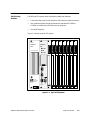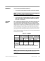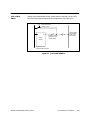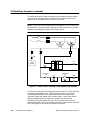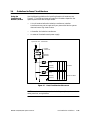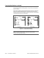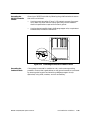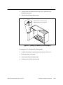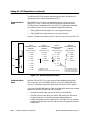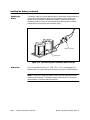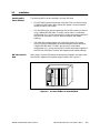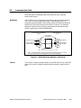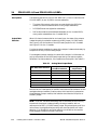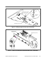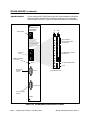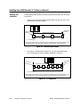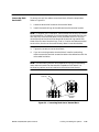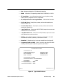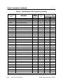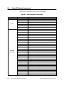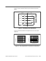
1
 !"
#$""
%& '&&(
!
DANGER
DANGER indicates an imminently hazardous situation that, if not avoided, will
result in death or serious injury.
DANGER is limited to the most extreme situations.
!
WARNING
WARNING indicates a potentially hazardous situation that, if not avoided, could
result in death or serious injury, and/or property damage.
!
CAUTION
CAUTION indicates a potentially hazardous situation that, if not avoided, could
result in minor or moderate injury, and/or damage to property.
CAUTION
CAUTION without the safety alert symbol indicates a potentially hazardous situation that, if not avoided, could result in property damage.
Copyright 2000 by Siemens Energy & Automation, Inc.
All Rights Reserved — Printed in USA
Reproduction, transmission, or use of this document or contents is not permitted without express consent of
Siemens Energy & Automation, Inc. All rights, including rights created by patent grant or registration of a utility model or design, are
reserved.
Since Siemens Energy & Automation, Inc., does not possess full access to data concerning all of the uses and applications of
customer’s products, we do not assume responsibility either for customer product design or for any infringements of patents or rights
of others which may result from our assistance.
MANUAL PUBLICATION HISTORY
SIMATIC 545/555/575 System Manual
Order Manual Number: PPX:505–8201–3
Refer to this history in all correspondence and/or discussion about this manual.
Event
Date
Description
Original Issue
Second Edition
Third Edition
03/96
08/98
06/00
Original Issue (2804693–0001)
Second Edition (2804693–0002)
Third Edition (2804693–0003)
LIST OF EFFECTIVE PAGES
Pages
Description
Cover/Copyright
History/Effective Pages
iii — xxi
1-1 — 1-13
2-1 — 2-20
3-1 — 3-28
4-1 — 4-58
5-1 — 5-24
6-1 — 6-35
7-1 — 7-12
8-1 — 8-8
9-1 — 9-25
A-1 — A-5
B-1 — B-9
C-1 — C-23
D-1 — D-7
E-1 — E-16
F-1 — F-6
Index-1 — Index-10
Registration
Third Edition
Third Edition
Third Edition
Third Edition
Third Edition
Third Edition
Third Edition
Third Edition
Third Edition
Third Edition
Third Edition
Third Edition
Third Edition
Third Edition
Third Edition
Third Edition
Third Edition
Third Edition
Third Edition
Third Edition
Pages
Description
Contents
Preface
Chapter 1
1.1
1.2
1.3
1.4
Overview . . . . . . . . . . . . . . . . . . . . . . . . . . . . . . . . . . . . . . . . . . . . . . . . . . . . . . . . . . . . . . . . . . . . . . .
1-2
Introduction . . . . . . . . . . . . . . . . . . . . . . . . . . . . . . . . . . . . . . . . . . . . . . . . . . . . . . . . . . . . . . . . . . . .
Compatibility with Previous CPUs . . . . . . . . . . . . . . . . . . . . . . . . . . . . . . . . . . . . . . . . . . . . . . . .
Features on New CPU Models . . . . . . . . . . . . . . . . . . . . . . . . . . . . . . . . . . . . . . . . . . . . . . . . . . .
PROFIBUS-DP . . . . . . . . . . . . . . . . . . . . . . . . . . . . . . . . . . . . . . . . . . . . . . . . . . . . . . . . . . . . . . . . . . .
PROFIBUS User Organizations . . . . . . . . . . . . . . . . . . . . . . . . . . . . . . . . . . . . . . . . . . . . . . . . . . . .
Using Other Networks . . . . . . . . . . . . . . . . . . . . . . . . . . . . . . . . . . . . . . . . . . . . . . . . . . . . . . . . . . .
1-2
1-2
1-3
1-4
1-4
1-4
System Features . . . . . . . . . . . . . . . . . . . . . . . . . . . . . . . . . . . . . . . . . . . . . . . . . . . . . . . . . . . . . . . .
1-6
Product Specifications Overview . . . . . . . . . . . . . . . . . . . . . . . . . . . . . . . . . . . . . . . . . . . . . . . .
Shared Features . . . . . . . . . . . . . . . . . . . . . . . . . . . . . . . . . . . . . . . . . . . . . . . . . . . . . . . . . . . . . . . .
545/555-Only Features . . . . . . . . . . . . . . . . . . . . . . . . . . . . . . . . . . . . . . . . . . . . . . . . . . . . . . . . . .
575-Only Features . . . . . . . . . . . . . . . . . . . . . . . . . . . . . . . . . . . . . . . . . . . . . . . . . . . . . . . . . . . . . . .
1-6
1-8
1-9
1-10
Programming Tools . . . . . . . . . . . . . . . . . . . . . . . . . . . . . . . . . . . . . . . . . . . . . . . . . . . . . . . . . . . . . .
1-11
SoftShop . . . . . . . . . . . . . . . . . . . . . . . . . . . . . . . . . . . . . . . . . . . . . . . . . . . . . . . . . . . . . . . . . . . . . . .
TISOFT . . . . . . . . . . . . . . . . . . . . . . . . . . . . . . . . . . . . . . . . . . . . . . . . . . . . . . . . . . . . . . . . . . . . . . . . . .
COM PROFIBUS . . . . . . . . . . . . . . . . . . . . . . . . . . . . . . . . . . . . . . . . . . . . . . . . . . . . . . . . . . . . . . . . .
Communicating with the CPU . . . . . . . . . . . . . . . . . . . . . . . . . . . . . . . . . . . . . . . . . . . . . . . . . . .
1-11
1-11
1-11
1-11
Hardware Overview . . . . . . . . . . . . . . . . . . . . . . . . . . . . . . . . . . . . . . . . . . . . . . . . . . . . . . . . . . . . .
1-12
Series 505 Bases . . . . . . . . . . . . . . . . . . . . . . . . . . . . . . . . . . . . . . . . . . . . . . . . . . . . . . . . . . . . . . . . .
VME Base . . . . . . . . . . . . . . . . . . . . . . . . . . . . . . . . . . . . . . . . . . . . . . . . . . . . . . . . . . . . . . . . . . . . . .
Expansion I/O . . . . . . . . . . . . . . . . . . . . . . . . . . . . . . . . . . . . . . . . . . . . . . . . . . . . . . . . . . . . . . . . . .
I/O Channel Support . . . . . . . . . . . . . . . . . . . . . . . . . . . . . . . . . . . . . . . . . . . . . . . . . . . . . . . . . . . .
1-12
1-12
1-13
1-13
Chapter 2
2.1
2.2
2.3
System Overview
Pre-installation Guidelines
Planning Your Installation . . . . . . . . . . . . . . . . . . . . . . . . . . . . . . . . . . . . . . . . . . . . . . . . . . . . . . . .
2-2
Defining Control Requirements . . . . . . . . . . . . . . . . . . . . . . . . . . . . . . . . . . . . . . . . . . . . . . . . . .
Calculating Power Needs . . . . . . . . . . . . . . . . . . . . . . . . . . . . . . . . . . . . . . . . . . . . . . . . . . . . . . .
2-2
2-2
Safety Considerations . . . . . . . . . . . . . . . . . . . . . . . . . . . . . . . . . . . . . . . . . . . . . . . . . . . . . . . . . . .
2-3
Operator Safety Switches . . . . . . . . . . . . . . . . . . . . . . . . . . . . . . . . . . . . . . . . . . . . . . . . . . . . . . .
Emergency Stop Switch . . . . . . . . . . . . . . . . . . . . . . . . . . . . . . . . . . . . . . . . . . . . . . . . . . . . . . . . .
JOG or INCH Switch . . . . . . . . . . . . . . . . . . . . . . . . . . . . . . . . . . . . . . . . . . . . . . . . . . . . . . . . . . . . .
2-4
2-4
2-5
575 Fault Relay Operation . . . . . . . . . . . . . . . . . . . . . . . . . . . . . . . . . . . . . . . . . . . . . . . . . . . . . . .
2-6
Overview . . . . . . . . . . . . . . . . . . . . . . . . . . . . . . . . . . . . . . . . . . . . . . . . . . . . . . . . . . . . . . . . . . . . . . .
Fault Relay Operation Details . . . . . . . . . . . . . . . . . . . . . . . . . . . . . . . . . . . . . . . . . . . . . . . . . . . .
Time Delay . . . . . . . . . . . . . . . . . . . . . . . . . . . . . . . . . . . . . . . . . . . . . . . . . . . . . . . . . . . . . . . . . . . . .
Fault Relay Usage Examples . . . . . . . . . . . . . . . . . . . . . . . . . . . . . . . . . . . . . . . . . . . . . . . . . . . . .
2-6
2-6
2-8
2-8
Contents
iii
2.4
Guidelines for Fuses/Circuit Breakers . . . . . . . . . . . . . . . . . . . . . . . . . . . . . . . . . . . . . . . . . . . . .
2-11
Fusing the Controller and Remote I/O Base . . . . . . . . . . . . . . . . . . . . . . . . . . . . . . . . . . . . . . .
2-11
Electrical Noise . . . . . . . . . . . . . . . . . . . . . . . . . . . . . . . . . . . . . . . . . . . . . . . . . . . . . . . . . . . . . . . . .
2-12
Definition and Source . . . . . . . . . . . . . . . . . . . . . . . . . . . . . . . . . . . . . . . . . . . . . . . . . . . . . . . . . . .
2-12
Correcting Noise Problems . . . . . . . . . . . . . . . . . . . . . . . . . . . . . . . . . . . . . . . . . . . . . . . . . . . . . .
2-13
Noise Snubbing . . . . . . . . . . . . . . . . . . . . . . . . . . . . . . . . . . . . . . . . . . . . . . . . . . . . . . . . . . . . . . . . .
Noise Isolation . . . . . . . . . . . . . . . . . . . . . . . . . . . . . . . . . . . . . . . . . . . . . . . . . . . . . . . . . . . . . . . . . .
2-13
2-15
2.7
Wiring Guidelines . . . . . . . . . . . . . . . . . . . . . . . . . . . . . . . . . . . . . . . . . . . . . . . . . . . . . . . . . . . . . . .
2-16
2.8
Grounding the Power System . . . . . . . . . . . . . . . . . . . . . . . . . . . . . . . . . . . . . . . . . . . . . . . . . . . .
2-17
Earth Ground . . . . . . . . . . . . . . . . . . . . . . . . . . . . . . . . . . . . . . . . . . . . . . . . . . . . . . . . . . . . . . . . . . .
Ground Connections . . . . . . . . . . . . . . . . . . . . . . . . . . . . . . . . . . . . . . . . . . . . . . . . . . . . . . . . . . .
Grounding the 545/555 Controller Chassis . . . . . . . . . . . . . . . . . . . . . . . . . . . . . . . . . . . . . . . .
Grounding the Cabinet or Rack . . . . . . . . . . . . . . . . . . . . . . . . . . . . . . . . . . . . . . . . . . . . . . . . .
Cable Management for the 575 . . . . . . . . . . . . . . . . . . . . . . . . . . . . . . . . . . . . . . . . . . . . . . . . .
Grounding the 575 Controller Chassis . . . . . . . . . . . . . . . . . . . . . . . . . . . . . . . . . . . . . . . . . . . .
Grounding the Cabinet or Rack . . . . . . . . . . . . . . . . . . . . . . . . . . . . . . . . . . . . . . . . . . . . . . . . .
2-17
2-18
2-19
2-19
2-20
2-20
2-20
2.5
2.6
Chapter 3
Installing 505 System Hardware
3.1
Overview of Installation Procedures . . . . . . . . . . . . . . . . . . . . . . . . . . . . . . . . . . . . . . . . . . . . . .
3-2
3.2
Enclosure and Temperature Considerations . . . . . . . . . . . . . . . . . . . . . . . . . . . . . . . . . . . . . .
3-3
Enclosure Selection . . . . . . . . . . . . . . . . . . . . . . . . . . . . . . . . . . . . . . . . . . . . . . . . . . . . . . . . . . . . .
Temperature Considerations . . . . . . . . . . . . . . . . . . . . . . . . . . . . . . . . . . . . . . . . . . . . . . . . . . . . .
3-3
3-3
Series 505 Bases . . . . . . . . . . . . . . . . . . . . . . . . . . . . . . . . . . . . . . . . . . . . . . . . . . . . . . . . . . . . . . . .
3-4
Description . . . . . . . . . . . . . . . . . . . . . . . . . . . . . . . . . . . . . . . . . . . . . . . . . . . . . . . . . . . . . . . . . . . . .
Grounding the Controller Chassis . . . . . . . . . . . . . . . . . . . . . . . . . . . . . . . . . . . . . . . . . . . . . . . .
3-4
3-4
3.4
Rack Mounting Series 505 Bases . . . . . . . . . . . . . . . . . . . . . . . . . . . . . . . . . . . . . . . . . . . . . . . . .
3-5
3.5
Panel Mounting Series 505 Bases . . . . . . . . . . . . . . . . . . . . . . . . . . . . . . . . . . . . . . . . . . . . . . . . .
3-6
3.6
Installing Series 505 Power Supply . . . . . . . . . . . . . . . . . . . . . . . . . . . . . . . . . . . . . . . . . . . . . . . .
3-8
Power Budget for Series 505 Base . . . . . . . . . . . . . . . . . . . . . . . . . . . . . . . . . . . . . . . . . . . . . . . .
Power Supply Placement in Bases . . . . . . . . . . . . . . . . . . . . . . . . . . . . . . . . . . . . . . . . . . . . . . . .
Installing and Removing the Power Supply . . . . . . . . . . . . . . . . . . . . . . . . . . . . . . . . . . . . . . .
Wiring the Power Supply . . . . . . . . . . . . . . . . . . . . . . . . . . . . . . . . . . . . . . . . . . . . . . . . . . . . . . . . .
3-8
3-8
3-8
3-10
3.7
Installing the PROFIBUS-DP Annex Card (Optional) . . . . . . . . . . . . . . . . . . . . . . . . . . . . . . . .
3-12
3.8
Installing the 545/555 CPU . . . . . . . . . . . . . . . . . . . . . . . . . . . . . . . . . . . . . . . . . . . . . . . . . . . . . . .
3-14
CPU/RBC Location in a Base . . . . . . . . . . . . . . . . . . . . . . . . . . . . . . . . . . . . . . . . . . . . . . . . . . . . .
Installing and Removing the CPU . . . . . . . . . . . . . . . . . . . . . . . . . . . . . . . . . . . . . . . . . . . . . . . .
3-14
3-14
3.3
iv
Contents
3.9
3.10
3.11
Replacing and Handling the Battery . . . . . . . . . . . . . . . . . . . . . . . . . . . . . . . . . . . . . . . . . . . . .
3-16
Lithium Battery in the 545 and 555 –1105/–1106 CPUs . . . . . . . . . . . . . . . . . . . . . . . . . . . . . .
Replacing the Battery in –1105/–1106 CPUs . . . . . . . . . . . . . . . . . . . . . . . . . . . . . . . . . . . . . . .
Lithium Battery in the 545 and 555 –1103/–1104 CPUs . . . . . . . . . . . . . . . . . . . . . . . . . . . . . .
Indicators . . . . . . . . . . . . . . . . . . . . . . . . . . . . . . . . . . . . . . . . . . . . . . . . . . . . . . . . . . . . . . . . . . . . . .
Using and Handling Batteries . . . . . . . . . . . . . . . . . . . . . . . . . . . . . . . . . . . . . . . . . . . . . . . . . . . .
Transporting Batteries . . . . . . . . . . . . . . . . . . . . . . . . . . . . . . . . . . . . . . . . . . . . . . . . . . . . . . . . . . .
Storing Batteries . . . . . . . . . . . . . . . . . . . . . . . . . . . . . . . . . . . . . . . . . . . . . . . . . . . . . . . . . . . . . . . .
Discarding Batteries . . . . . . . . . . . . . . . . . . . . . . . . . . . . . . . . . . . . . . . . . . . . . . . . . . . . . . . . . . . . .
Replacing the Battery in –1103/–1104 CPUs . . . . . . . . . . . . . . . . . . . . . . . . . . . . . . . . . . . . . . .
3-16
3-17
3-18
3-18
3-19
3-19
3-19
3-19
3-20
Setting the CPU Dipswitches . . . . . . . . . . . . . . . . . . . . . . . . . . . . . . . . . . . . . . . . . . . . . . . . . . . . .
3-22
Dipswitch Location and Settings . . . . . . . . . . . . . . . . . . . . . . . . . . . . . . . . . . . . . . . . . . . . . . . . .
Enabling Battery Backup . . . . . . . . . . . . . . . . . . . . . . . . . . . . . . . . . . . . . . . . . . . . . . . . . . . . . . . .
Enabling the Auto Recompile Function . . . . . . . . . . . . . . . . . . . . . . . . . . . . . . . . . . . . . . . . . . .
Setting Baud Rates . . . . . . . . . . . . . . . . . . . . . . . . . . . . . . . . . . . . . . . . . . . . . . . . . . . . . . . . . . . . . .
Communications Port 1 . . . . . . . . . . . . . . . . . . . . . . . . . . . . . . . . . . . . . . . . . . . . . . . . . . . . . . . . .
Communications Port 2 . . . . . . . . . . . . . . . . . . . . . . . . . . . . . . . . . . . . . . . . . . . . . . . . . . . . . . . . .
I/O Ports . . . . . . . . . . . . . . . . . . . . . . . . . . . . . . . . . . . . . . . . . . . . . . . . . . . . . . . . . . . . . . . . . . . . . . . .
3-22
3-22
3-22
3-23
3-24
3-24
3-25
Installing Series 505 I/O Modules . . . . . . . . . . . . . . . . . . . . . . . . . . . . . . . . . . . . . . . . . . . . . . . . .
3-26
Mixing I/O Modules . . . . . . . . . . . . . . . . . . . . . . . . . . . . . . . . . . . . . . . . . . . . . . . . . . . . . . . . . . . . .
Installing and Removing I/O Modules . . . . . . . . . . . . . . . . . . . . . . . . . . . . . . . . . . . . . . . . . . . .
3-26
3-26
Chapter 4
Installing 575 System Hardware
4.1
Overview of Installation Procedures . . . . . . . . . . . . . . . . . . . . . . . . . . . . . . . . . . . . . . . . . . . . . .
4-2
4.2
Features of the PPX:575–2130 VMEbus Base . . . . . . . . . . . . . . . . . . . . . . . . . . . . . . . . . . . . . . .
4-3
Overview . . . . . . . . . . . . . . . . . . . . . . . . . . . . . . . . . . . . . . . . . . . . . . . . . . . . . . . . . . . . . . . . . . . . . . .
4-3
Features Required of a Third-Party VMEbus Base . . . . . . . . . . . . . . . . . . . . . . . . . . . . . . . . . .
4-4
VMEbus Base Requirements . . . . . . . . . . . . . . . . . . . . . . . . . . . . . . . . . . . . . . . . . . . . . . . . . . . . .
Determining the Condition of the 575 CPU Battery . . . . . . . . . . . . . . . . . . . . . . . . . . . . . . . .
4-4
4-4
Enclosure and Temperature Considerations . . . . . . . . . . . . . . . . . . . . . . . . . . . . . . . . . . . . . .
4-5
Enclosure Selection . . . . . . . . . . . . . . . . . . . . . . . . . . . . . . . . . . . . . . . . . . . . . . . . . . . . . . . . . . . . .
Temperature Considerations . . . . . . . . . . . . . . . . . . . . . . . . . . . . . . . . . . . . . . . . . . . . . . . . . . . . .
4-5
4-5
Installing the Fan Assembly . . . . . . . . . . . . . . . . . . . . . . . . . . . . . . . . . . . . . . . . . . . . . . . . . . . . . .
4-6
Operating With Fan Assembly . . . . . . . . . . . . . . . . . . . . . . . . . . . . . . . . . . . . . . . . . . . . . . . . . . .
Operating Without Fan Assembly . . . . . . . . . . . . . . . . . . . . . . . . . . . . . . . . . . . . . . . . . . . . . . . .
Installation Sequence . . . . . . . . . . . . . . . . . . . . . . . . . . . . . . . . . . . . . . . . . . . . . . . . . . . . . . . . . . .
Selecting Voltage for Fan Operation . . . . . . . . . . . . . . . . . . . . . . . . . . . . . . . . . . . . . . . . . . . . .
Wiring the AC Power Terminals . . . . . . . . . . . . . . . . . . . . . . . . . . . . . . . . . . . . . . . . . . . . . . . . . . .
Mounting the Fan Assembly . . . . . . . . . . . . . . . . . . . . . . . . . . . . . . . . . . . . . . . . . . . . . . . . . . . . .
Replacing Fuse on the Fan Assembly . . . . . . . . . . . . . . . . . . . . . . . . . . . . . . . . . . . . . . . . . . . . .
4-6
4-6
4-6
4-7
4-7
4-8
4-9
4.3
4.4
4.5
Contents
v
4.6
Installing the PPX:575–2130 VMEbus Base . . . . . . . . . . . . . . . . . . . . . . . . . . . . . . . . . . . . . . . . .
4-10
Mechanical Outline . . . . . . . . . . . . . . . . . . . . . . . . . . . . . . . . . . . . . . . . . . . . . . . . . . . . . . . . . . . . .
Mounting Measurements . . . . . . . . . . . . . . . . . . . . . . . . . . . . . . . . . . . . . . . . . . . . . . . . . . . . . . . .
Mounting a Base in a 19-inch Rack . . . . . . . . . . . . . . . . . . . . . . . . . . . . . . . . . . . . . . . . . . . . . .
NEMA Cabinet Mounting Measurements . . . . . . . . . . . . . . . . . . . . . . . . . . . . . . . . . . . . . . . . .
Panel Mounting the Base . . . . . . . . . . . . . . . . . . . . . . . . . . . . . . . . . . . . . . . . . . . . . . . . . . . . . . . .
Grounding the Controller Chassis . . . . . . . . . . . . . . . . . . . . . . . . . . . . . . . . . . . . . . . . . . . . . . . .
4-10
4-10
4-11
4-12
4-12
4-13
Installing the 575 Power Supply . . . . . . . . . . . . . . . . . . . . . . . . . . . . . . . . . . . . . . . . . . . . . . . . . .
4-14
Overview . . . . . . . . . . . . . . . . . . . . . . . . . . . . . . . . . . . . . . . . . . . . . . . . . . . . . . . . . . . . . . . . . . . . . . .
Selecting Input Voltage (PPX:575–6663 Only) . . . . . . . . . . . . . . . . . . . . . . . . . . . . . . . . . . . . .
Installing the 575 Power Supply . . . . . . . . . . . . . . . . . . . . . . . . . . . . . . . . . . . . . . . . . . . . . . . . . .
Wiring Guidelines . . . . . . . . . . . . . . . . . . . . . . . . . . . . . . . . . . . . . . . . . . . . . . . . . . . . . . . . . . . . . . .
Wiring Procedure . . . . . . . . . . . . . . . . . . . . . . . . . . . . . . . . . . . . . . . . . . . . . . . . . . . . . . . . . . . . . . .
4-14
4-16
4-17
4-17
4-18
Installing the Battery . . . . . . . . . . . . . . . . . . . . . . . . . . . . . . . . . . . . . . . . . . . . . . . . . . . . . . . . . . . .
4-20
Battery Backup for the 575 . . . . . . . . . . . . . . . . . . . . . . . . . . . . . . . . . . . . . . . . . . . . . . . . . . . . . .
Mounting the Battery . . . . . . . . . . . . . . . . . . . . . . . . . . . . . . . . . . . . . . . . . . . . . . . . . . . . . . . . . . .
Disabling the Battery . . . . . . . . . . . . . . . . . . . . . . . . . . . . . . . . . . . . . . . . . . . . . . . . . . . . . . . . . . . .
Battery Fuse . . . . . . . . . . . . . . . . . . . . . . . . . . . . . . . . . . . . . . . . . . . . . . . . . . . . . . . . . . . . . . . . . . . .
4-20
4-20
4-22
4-22
4.9
Installing the Floating-Point Coprocessor (Optional) . . . . . . . . . . . . . . . . . . . . . . . . . . . . . . .
4-23
4.10
Configuring the CPU . . . . . . . . . . . . . . . . . . . . . . . . . . . . . . . . . . . . . . . . . . . . . . . . . . . . . . . . . . . .
4-24
Configuring the 575–2105/–2106 CPU . . . . . . . . . . . . . . . . . . . . . . . . . . . . . . . . . . . . . . . . . . . .
Configuring the 575–2104 CPU . . . . . . . . . . . . . . . . . . . . . . . . . . . . . . . . . . . . . . . . . . . . . . . . . . .
Using the AUTO-CONFIGURED Mode . . . . . . . . . . . . . . . . . . . . . . . . . . . . . . . . . . . . . . . . . . . . .
Using the USER-CONFIGURED Mode . . . . . . . . . . . . . . . . . . . . . . . . . . . . . . . . . . . . . . . . . . . . . .
Configuring the 575 Primary and Secondaries . . . . . . . . . . . . . . . . . . . . . . . . . . . . . . . . . . . .
Enabling the Auto Recompile Function . . . . . . . . . . . . . . . . . . . . . . . . . . . . . . . . . . . . . . . . . . .
Setting the Base Address . . . . . . . . . . . . . . . . . . . . . . . . . . . . . . . . . . . . . . . . . . . . . . . . . . . . . . . .
Issuing SYSRESET . . . . . . . . . . . . . . . . . . . . . . . . . . . . . . . . . . . . . . . . . . . . . . . . . . . . . . . . . . . . . . . . .
4-24
4-24
4-26
4-26
4-26
4-26
4-27
4-27
Installing a Remote I/O Annex Card (Optional) . . . . . . . . . . . . . . . . . . . . . . . . . . . . . . . . . . .
4-28
Configuring Annex Card Dipswitch . . . . . . . . . . . . . . . . . . . . . . . . . . . . . . . . . . . . . . . . . . . . . .
Annex Card Power Consumption . . . . . . . . . . . . . . . . . . . . . . . . . . . . . . . . . . . . . . . . . . . . . . . .
Installing the Series 505 Remote I/O Annex Card . . . . . . . . . . . . . . . . . . . . . . . . . . . . . . . . . .
Installing the PROFIBUS-DP Annex Card . . . . . . . . . . . . . . . . . . . . . . . . . . . . . . . . . . . . . . . . . . .
4-28
4-28
4-29
4-30
Installing VMEbus Boards . . . . . . . . . . . . . . . . . . . . . . . . . . . . . . . . . . . . . . . . . . . . . . . . . . . . . . . .
4-32
Introduction . . . . . . . . . . . . . . . . . . . . . . . . . . . . . . . . . . . . . . . . . . . . . . . . . . . . . . . . . . . . . . . . . . . .
General Guidelines . . . . . . . . . . . . . . . . . . . . . . . . . . . . . . . . . . . . . . . . . . . . . . . . . . . . . . . . . . . . .
Guidelines for Installing a 575 System Controller or a Primary 575 . . . . . . . . . . . . . . . . . . .
Guidelines for Installing or Adding a 575 Secondary to the System . . . . . . . . . . . . . . . . .
Guidelines for Replacing a 575 System Controller . . . . . . . . . . . . . . . . . . . . . . . . . . . . . . . . .
Guidelines for Replacing a 575 Primary Not in Slot 1 . . . . . . . . . . . . . . . . . . . . . . . . . . . . . . .
Guidelines for Replacing a 575 Secondary . . . . . . . . . . . . . . . . . . . . . . . . . . . . . . . . . . . . . . .
Guidelines for Installing SIMATIC VMEbus I/O and Third-Party Boards . . . . . . . . . . . . . . . .
Setting the Daisy-Chain Switches . . . . . . . . . . . . . . . . . . . . . . . . . . . . . . . . . . . . . . . . . . . . . . . .
Slot Numbering . . . . . . . . . . . . . . . . . . . . . . . . . . . . . . . . . . . . . . . . . . . . . . . . . . . . . . . . . . . . . . . . .
Installing and Removing I/O Modules . . . . . . . . . . . . . . . . . . . . . . . . . . . . . . . . . . . . . . . . . . . .
4-32
4-34
4-35
4-36
4-37
4-38
4-39
4-40
4-41
4-41
4-42
4.7
4.8
4.11
4.12
vi
Contents
4.13
Wiring the Fault Relay . . . . . . . . . . . . . . . . . . . . . . . . . . . . . . . . . . . . . . . . . . . . . . . . . . . . . . . . . . .
4-44
4.14
Establishing CPU Communication . . . . . . . . . . . . . . . . . . . . . . . . . . . . . . . . . . . . . . . . . . . . . . . .
4-45
Default Port Configurations . . . . . . . . . . . . . . . . . . . . . . . . . . . . . . . . . . . . . . . . . . . . . . . . . . . . . .
Pinout for Serial Port 1 . . . . . . . . . . . . . . . . . . . . . . . . . . . . . . . . . . . . . . . . . . . . . . . . . . . . . . . . . . .
Pinouts for Serial Ports 2, 3, and 4 . . . . . . . . . . . . . . . . . . . . . . . . . . . . . . . . . . . . . . . . . . . . . . . . .
Serial Port 1 . . . . . . . . . . . . . . . . . . . . . . . . . . . . . . . . . . . . . . . . . . . . . . . . . . . . . . . . . . . . . . . . . . . . .
Serial Port 2/ Printer Port . . . . . . . . . . . . . . . . . . . . . . . . . . . . . . . . . . . . . . . . . . . . . . . . . . . . . . . . .
Serial Port 3 . . . . . . . . . . . . . . . . . . . . . . . . . . . . . . . . . . . . . . . . . . . . . . . . . . . . . . . . . . . . . . . . . . . . .
Serial Port 4 . . . . . . . . . . . . . . . . . . . . . . . . . . . . . . . . . . . . . . . . . . . . . . . . . . . . . . . . . . . . . . . . . . . . .
4-45
4-46
4-46
4-47
4-48
4-49
4-49
Using Boards in the VMEbus Base . . . . . . . . . . . . . . . . . . . . . . . . . . . . . . . . . . . . . . . . . . . . . . . .
4-50
Communicating with the CPU . . . . . . . . . . . . . . . . . . . . . . . . . . . . . . . . . . . . . . . . . . . . . . . . . . .
Battery Status . . . . . . . . . . . . . . . . . . . . . . . . . . . . . . . . . . . . . . . . . . . . . . . . . . . . . . . . . . . . . . . . . . .
Using VMEbus Address Space . . . . . . . . . . . . . . . . . . . . . . . . . . . . . . . . . . . . . . . . . . . . . . . . . . .
Daisy-Chain Signals . . . . . . . . . . . . . . . . . . . . . . . . . . . . . . . . . . . . . . . . . . . . . . . . . . . . . . . . . . . . .
Assigning Addresses to Third-Party Slaves . . . . . . . . . . . . . . . . . . . . . . . . . . . . . . . . . . . . . . . . .
VMEbus Access Limitations . . . . . . . . . . . . . . . . . . . . . . . . . . . . . . . . . . . . . . . . . . . . . . . . . . . . . .
4-50
4-51
4-51
4-53
4-53
4-55
Installing Additional Backplane Connectors . . . . . . . . . . . . . . . . . . . . . . . . . . . . . . . . . . . . . .
4-56
J2 Backplanes . . . . . . . . . . . . . . . . . . . . . . . . . . . . . . . . . . . . . . . . . . . . . . . . . . . . . . . . . . . . . . . . . .
Optional J2 Mini Backplane Kit . . . . . . . . . . . . . . . . . . . . . . . . . . . . . . . . . . . . . . . . . . . . . . . . . .
Installing Optional J2 Backplane . . . . . . . . . . . . . . . . . . . . . . . . . . . . . . . . . . . . . . . . . . . . . . . . .
Installing Optional J2 DIN Connector . . . . . . . . . . . . . . . . . . . . . . . . . . . . . . . . . . . . . . . . . . . . .
4-56
4-56
4-57
4-58
4.15
4.16
Chapter 5
Installing Remote Base Controllers—RBCs
5.1
Overview . . . . . . . . . . . . . . . . . . . . . . . . . . . . . . . . . . . . . . . . . . . . . . . . . . . . . . . . . . . . . . . . . . . . . . .
5-2
5.2
Installation . . . . . . . . . . . . . . . . . . . . . . . . . . . . . . . . . . . . . . . . . . . . . . . . . . . . . . . . . . . . . . . . . . . . .
5-3
Models Used in Series 505 Base . . . . . . . . . . . . . . . . . . . . . . . . . . . . . . . . . . . . . . . . . . . . . . . . . .
RBC Placement in Base . . . . . . . . . . . . . . . . . . . . . . . . . . . . . . . . . . . . . . . . . . . . . . . . . . . . . . . . .
Installing and Removing the RBC . . . . . . . . . . . . . . . . . . . . . . . . . . . . . . . . . . . . . . . . . . . . . . . .
5-3
5-3
5-4
Communication Ports . . . . . . . . . . . . . . . . . . . . . . . . . . . . . . . . . . . . . . . . . . . . . . . . . . . . . . . . . . .
5-5
RS-232 Port . . . . . . . . . . . . . . . . . . . . . . . . . . . . . . . . . . . . . . . . . . . . . . . . . . . . . . . . . . . . . . . . . . . . .
I/O Port . . . . . . . . . . . . . . . . . . . . . . . . . . . . . . . . . . . . . . . . . . . . . . . . . . . . . . . . . . . . . . . . . . . . . . . .
5-5
5-5
PPX:505–6851–A/B and PPX:505–6850–A/B RBCs . . . . . . . . . . . . . . . . . . . . . . . . . . . . . . . . . .
5-6
User Options . . . . . . . . . . . . . . . . . . . . . . . . . . . . . . . . . . . . . . . . . . . . . . . . . . . . . . . . . . . . . . . . . . . .
Output State Selection . . . . . . . . . . . . . . . . . . . . . . . . . . . . . . . . . . . . . . . . . . . . . . . . . . . . . . . . . .
Dipswitch Options . . . . . . . . . . . . . . . . . . . . . . . . . . . . . . . . . . . . . . . . . . . . . . . . . . . . . . . . . . . . . .
Series 505 Base Numbers . . . . . . . . . . . . . . . . . . . . . . . . . . . . . . . . . . . . . . . . . . . . . . . . . . . . . . . .
Changing the RBC Base Number . . . . . . . . . . . . . . . . . . . . . . . . . . . . . . . . . . . . . . . . . . . . . . . .
Resetting the RBC . . . . . . . . . . . . . . . . . . . . . . . . . . . . . . . . . . . . . . . . . . . . . . . . . . . . . . . . . . . . . . .
Status Display . . . . . . . . . . . . . . . . . . . . . . . . . . . . . . . . . . . . . . . . . . . . . . . . . . . . . . . . . . . . . . . . . . .
5-6
5-6
5-8
5-9
5-9
5-11
5-12
5.3
5.4
Contents
vii
5.5
PPX:505–6870 RBC . . . . . . . . . . . . . . . . . . . . . . . . . . . . . . . . . . . . . . . . . . . . . . . . . . . . . . . . . . . . . .
User Options . . . . . . . . . . . . . . . . . . . . . . . . . . . . . . . . . . . . . . . . . . . . . . . . . . . . . . . . . . . . . . . . . . . .
Output State Selection . . . . . . . . . . . . . . . . . . . . . . . . . . . . . . . . . . . . . . . . . . . . . . . . . . . . . . . . . .
Jumpers E2, E3 and E4 . . . . . . . . . . . . . . . . . . . . . . . . . . . . . . . . . . . . . . . . . . . . . . . . . . . . . . . . . .
Dipswitch Options . . . . . . . . . . . . . . . . . . . . . . . . . . . . . . . . . . . . . . . . . . . . . . . . . . . . . . . . . . . . . .
Baud Rate for the RS-232 Port . . . . . . . . . . . . . . . . . . . . . . . . . . . . . . . . . . . . . . . . . . . . . . . . . . . .
Assigning the RBC Station Address . . . . . . . . . . . . . . . . . . . . . . . . . . . . . . . . . . . . . . . . . . . . . . .
Reset Pushbutton . . . . . . . . . . . . . . . . . . . . . . . . . . . . . . . . . . . . . . . . . . . . . . . . . . . . . . . . . . . . . . .
Resetting the RBC . . . . . . . . . . . . . . . . . . . . . . . . . . . . . . . . . . . . . . . . . . . . . . . . . . . . . . . . . . . . . . .
Status Display Mode . . . . . . . . . . . . . . . . . . . . . . . . . . . . . . . . . . . . . . . . . . . . . . . . . . . . . . . . . . . .
Setting User Parameters for the 505 PROFIBUS-DP RBC . . . . . . . . . . . . . . . . . . . . . . . . . . . . .
Discrete I/O Interval . . . . . . . . . . . . . . . . . . . . . . . . . . . . . . . . . . . . . . . . . . . . . . . . . . . . . . . . . . . . .
Word I/O Update Factor . . . . . . . . . . . . . . . . . . . . . . . . . . . . . . . . . . . . . . . . . . . . . . . . . . . . . . . .
50X Ignore Mismatch Mode . . . . . . . . . . . . . . . . . . . . . . . . . . . . . . . . . . . . . . . . . . . . . . . . . . . . .
50X RS-232 Comm Port . . . . . . . . . . . . . . . . . . . . . . . . . . . . . . . . . . . . . . . . . . . . . . . . . . . . . . . . . .
Chapter 6
6.1
5-14
5-14
5-14
5-15
5-16
5-17
5-17
5-20
5-20
5-22
5-24
5-24
5-24
5-24
5-24
Cabling and Wiring the System
Cable Routing . . . . . . . . . . . . . . . . . . . . . . . . . . . . . . . . . . . . . . . . . . . . . . . . . . . . . . . . . . . . . . . . . .
6-2
Guidelines . . . . . . . . . . . . . . . . . . . . . . . . . . . . . . . . . . . . . . . . . . . . . . . . . . . . . . . . . . . . . . . . . . . . . .
Cable Routing Methods . . . . . . . . . . . . . . . . . . . . . . . . . . . . . . . . . . . . . . . . . . . . . . . . . . . . . . . . .
Under-Floor Routing . . . . . . . . . . . . . . . . . . . . . . . . . . . . . . . . . . . . . . . . . . . . . . . . . . . . . . . . . . . . .
In-Ceiling Routing . . . . . . . . . . . . . . . . . . . . . . . . . . . . . . . . . . . . . . . . . . . . . . . . . . . . . . . . . . . . . . .
Surface Duct Routing . . . . . . . . . . . . . . . . . . . . . . . . . . . . . . . . . . . . . . . . . . . . . . . . . . . . . . . . . . .
6-2
6-2
6-3
6-3
6-3
6.2
Installing Series 505 Remote I/O Cables . . . . . . . . . . . . . . . . . . . . . . . . . . . . . . . . . . . . . . . . . .
Media Options . . . . . . . . . . . . . . . . . . . . . . . . . . . . . . . . . . . . . . . . . . . . . . . . . . . . . . . . . . . . . . . . .
Equipment Needed . . . . . . . . . . . . . . . . . . . . . . . . . . . . . . . . . . . . . . . . . . . . . . . . . . . . . . . . . . . . .
Mounting Taps or Terminal Blocks . . . . . . . . . . . . . . . . . . . . . . . . . . . . . . . . . . . . . . . . . . . . . . . .
Trunk and Drop Lines . . . . . . . . . . . . . . . . . . . . . . . . . . . . . . . . . . . . . . . . . . . . . . . . . . . . . . . . . . . .
Selecting Cable . . . . . . . . . . . . . . . . . . . . . . . . . . . . . . . . . . . . . . . . . . . . . . . . . . . . . . . . . . . . . . . .
Planning Your Installation . . . . . . . . . . . . . . . . . . . . . . . . . . . . . . . . . . . . . . . . . . . . . . . . . . . . . . . .
Preparing Drop Line Cables . . . . . . . . . . . . . . . . . . . . . . . . . . . . . . . . . . . . . . . . . . . . . . . . . . . . .
Remote I/O Port Pinout . . . . . . . . . . . . . . . . . . . . . . . . . . . . . . . . . . . . . . . . . . . . . . . . . . . . . . . . . .
Connecting a Drop Line . . . . . . . . . . . . . . . . . . . . . . . . . . . . . . . . . . . . . . . . . . . . . . . . . . . . . . . . .
Preparing Trunk Line Cables . . . . . . . . . . . . . . . . . . . . . . . . . . . . . . . . . . . . . . . . . . . . . . . . . . . . .
Connecting Trunk Line Cables . . . . . . . . . . . . . . . . . . . . . . . . . . . . . . . . . . . . . . . . . . . . . . . . . . .
Extending Trunk Line Cables . . . . . . . . . . . . . . . . . . . . . . . . . . . . . . . . . . . . . . . . . . . . . . . . . . . . .
6-4
6-4
6-4
6-4
6-5
6-6
6-8
6-12
6-13
6-14
6-16
6-17
6-18
6.3
Installing PROFIBUS-DP I/O Cables . . . . . . . . . . . . . . . . . . . . . . . . . . . . . . . . . . . . . . . . . . . . . . .
Media Options . . . . . . . . . . . . . . . . . . . . . . . . . . . . . . . . . . . . . . . . . . . . . . . . . . . . . . . . . . . . . . . . .
System Layout . . . . . . . . . . . . . . . . . . . . . . . . . . . . . . . . . . . . . . . . . . . . . . . . . . . . . . . . . . . . . . . . . .
Equipment Needed . . . . . . . . . . . . . . . . . . . . . . . . . . . . . . . . . . . . . . . . . . . . . . . . . . . . . . . . . . . . .
PROFIBUS-DP Cable and Connector Specifications . . . . . . . . . . . . . . . . . . . . . . . . . . . . . . .
PROFIBUS-DP Line Length Limits . . . . . . . . . . . . . . . . . . . . . . . . . . . . . . . . . . . . . . . . . . . . . . . . . .
Installing PROFIBUS-DP Cable . . . . . . . . . . . . . . . . . . . . . . . . . . . . . . . . . . . . . . . . . . . . . . . . . . . .
Termination and Bias . . . . . . . . . . . . . . . . . . . . . . . . . . . . . . . . . . . . . . . . . . . . . . . . . . . . . . . . . . . .
Using a Termination Selection Switch . . . . . . . . . . . . . . . . . . . . . . . . . . . . . . . . . . . . . . . . . . . . .
PROFIBUS-DP Connector Schematics . . . . . . . . . . . . . . . . . . . . . . . . . . . . . . . . . . . . . . . . . . . . .
Installing a PROFIBUS-DP Connector . . . . . . . . . . . . . . . . . . . . . . . . . . . . . . . . . . . . . . . . . . . . . .
PROFIBUS-DP Port Pinout . . . . . . . . . . . . . . . . . . . . . . . . . . . . . . . . . . . . . . . . . . . . . . . . . . . . . . . . .
6-20
6-20
6-20
6-21
6-22
6-22
6-23
6-24
6-25
6-26
6-28
6-31
viii
Contents
6.4
6.5
Connecting Modems . . . . . . . . . . . . . . . . . . . . . . . . . . . . . . . . . . . . . . . . . . . . . . . . . . . . . . . . . . .
6-32
Overview . . . . . . . . . . . . . . . . . . . . . . . . . . . . . . . . . . . . . . . . . . . . . . . . . . . . . . . . . . . . . . . . . . . . . . .
Dedicated Line Operation . . . . . . . . . . . . . . . . . . . . . . . . . . . . . . . . . . . . . . . . . . . . . . . . . . . . . .
Dial-up Phone Line Operation . . . . . . . . . . . . . . . . . . . . . . . . . . . . . . . . . . . . . . . . . . . . . . . . . . .
6-32
6-33
6-33
Connecting to a Printer . . . . . . . . . . . . . . . . . . . . . . . . . . . . . . . . . . . . . . . . . . . . . . . . . . . . . . . . . .
6-34
Overview . . . . . . . . . . . . . . . . . . . . . . . . . . . . . . . . . . . . . . . . . . . . . . . . . . . . . . . . . . . . . . . . . . . . . . .
545/555 Printer Connections . . . . . . . . . . . . . . . . . . . . . . . . . . . . . . . . . . . . . . . . . . . . . . . . . . . . .
575 Printer Connections . . . . . . . . . . . . . . . . . . . . . . . . . . . . . . . . . . . . . . . . . . . . . . . . . . . . . . . . .
6-34
6-34
6-35
Chapter 7
7.1
Using EEPROMs for Program Storage
Program Storage Options . . . . . . . . . . . . . . . . . . . . . . . . . . . . . . . . . . . . . . . . . . . . . . . . . . . . . . . .
7-2
Overview . . . . . . . . . . . . . . . . . . . . . . . . . . . . . . . . . . . . . . . . . . . . . . . . . . . . . . . . . . . . . . . . . . . . . . .
On-Board Flash EEPROM Program Storage . . . . . . . . . . . . . . . . . . . . . . . . . . . . . . . . . . . . . . .
Optional Portable (E)EPROM Program Storage . . . . . . . . . . . . . . . . . . . . . . . . . . . . . . . . . . .
EEPROM Portability . . . . . . . . . . . . . . . . . . . . . . . . . . . . . . . . . . . . . . . . . . . . . . . . . . . . . . . . . . . . . .
Using an EEPROM . . . . . . . . . . . . . . . . . . . . . . . . . . . . . . . . . . . . . . . . . . . . . . . . . . . . . . . . . . . . . . .
Using an EPROM . . . . . . . . . . . . . . . . . . . . . . . . . . . . . . . . . . . . . . . . . . . . . . . . . . . . . . . . . . . . . . . .
What is Stored in Non-Volatile Memory . . . . . . . . . . . . . . . . . . . . . . . . . . . . . . . . . . . . . . . . . . .
Program Storage Operations . . . . . . . . . . . . . . . . . . . . . . . . . . . . . . . . . . . . . . . . . . . . . . . . . . . .
Memory and Mode Status at Powerup . . . . . . . . . . . . . . . . . . . . . . . . . . . . . . . . . . . . . . . . . . .
7-2
7-2
7-2
7-3
7-3
7-3
7-4
7-5
7-5
Configuring the CPU for Non-Volatile EEPROM Program Storage . . . . . . . . . . . . . . . . . . . .
7-6
Configuring the CPU for Portable EEPROM Usage . . . . . . . . . . . . . . . . . . . . . . . . . . . . . . . . .
Configuring the CPU for On-Board EEPROM Usage . . . . . . . . . . . . . . . . . . . . . . . . . . . . . . . .
7-6
7-8
7.3
Copying a Program into an EEPROM . . . . . . . . . . . . . . . . . . . . . . . . . . . . . . . . . . . . . . . . . . . . .
7-10
7.4
Editing a Program Stored in an EEPROM . . . . . . . . . . . . . . . . . . . . . . . . . . . . . . . . . . . . . . . . . .
7-12
7.2
Chapter 8
8.1
8.2
Starting Up the System
Powering Up the System . . . . . . . . . . . . . . . . . . . . . . . . . . . . . . . . . . . . . . . . . . . . . . . . . . . . . . . . .
8-2
Overview . . . . . . . . . . . . . . . . . . . . . . . . . . . . . . . . . . . . . . . . . . . . . . . . . . . . . . . . . . . . . . . . . . . . . . .
Start-up Procedures . . . . . . . . . . . . . . . . . . . . . . . . . . . . . . . . . . . . . . . . . . . . . . . . . . . . . . . . . . . . .
8-2
8-2
CPU Memory Configuration . . . . . . . . . . . . . . . . . . . . . . . . . . . . . . . . . . . . . . . . . . . . . . . . . . . . . .
8-4
Memory Configuration . . . . . . . . . . . . . . . . . . . . . . . . . . . . . . . . . . . . . . . . . . . . . . . . . . . . . . . . . .
Maximum Configurable Memory . . . . . . . . . . . . . . . . . . . . . . . . . . . . . . . . . . . . . . . . . . . . . . . .
8-4
8-4
Contents
ix
Chapter 9
9.1
Troubleshooting
Troubleshooting by Using Auxiliary Functions . . . . . . . . . . . . . . . . . . . . . . . . . . . . . . . . . . . . .
9-2
Overview . . . . . . . . . . . . . . . . . . . . . . . . . . . . . . . . . . . . . . . . . . . . . . . . . . . . . . . . . . . . . . . . . . . . . . .
Power-up Restart, Partial Restart, and Complete Restart . . . . . . . . . . . . . . . . . . . . . . . . . .
575 Fault Restarts . . . . . . . . . . . . . . . . . . . . . . . . . . . . . . . . . . . . . . . . . . . . . . . . . . . . . . . . . . . . . . .
Compare PLC to Disk . . . . . . . . . . . . . . . . . . . . . . . . . . . . . . . . . . . . . . . . . . . . . . . . . . . . . . . . . . .
Run 545/555 PLC Diagnostics . . . . . . . . . . . . . . . . . . . . . . . . . . . . . . . . . . . . . . . . . . . . . . . . . . . .
Display Failed I/O . . . . . . . . . . . . . . . . . . . . . . . . . . . . . . . . . . . . . . . . . . . . . . . . . . . . . . . . . . . . . . .
PLC Operational Status . . . . . . . . . . . . . . . . . . . . . . . . . . . . . . . . . . . . . . . . . . . . . . . . . . . . . . . . .
9-2
9-2
9-2
9-4
9-4
9-4
9-4
Troubleshooting by Reading LEDs . . . . . . . . . . . . . . . . . . . . . . . . . . . . . . . . . . . . . . . . . . . . . . . .
9-6
545/555 LEDs . . . . . . . . . . . . . . . . . . . . . . . . . . . . . . . . . . . . . . . . . . . . . . . . . . . . . . . . . . . . . . . . . . .
575 LEDs . . . . . . . . . . . . . . . . . . . . . . . . . . . . . . . . . . . . . . . . . . . . . . . . . . . . . . . . . . . . . . . . . . . . . . . .
9-6
9-7
Troubleshooting CPU Fatal Errors . . . . . . . . . . . . . . . . . . . . . . . . . . . . . . . . . . . . . . . . . . . . . . . . .
9-8
545/555 CPU Fatal Error Indications . . . . . . . . . . . . . . . . . . . . . . . . . . . . . . . . . . . . . . . . . . . . . .
575 CPU Fatal Error Indications . . . . . . . . . . . . . . . . . . . . . . . . . . . . . . . . . . . . . . . . . . . . . . . . . . .
Causes of CPU Fatal Errors . . . . . . . . . . . . . . . . . . . . . . . . . . . . . . . . . . . . . . . . . . . . . . . . . . . . . . .
545/555 Fatal Errors . . . . . . . . . . . . . . . . . . . . . . . . . . . . . . . . . . . . . . . . . . . . . . . . . . . . . . . . . . . . .
575 Fatal Errors . . . . . . . . . . . . . . . . . . . . . . . . . . . . . . . . . . . . . . . . . . . . . . . . . . . . . . . . . . . . . . . . . .
545/555/575 CPU Fatal Error Codes . . . . . . . . . . . . . . . . . . . . . . . . . . . . . . . . . . . . . . . . . . . . . .
545/555 CPU Responses to Fatal Errors . . . . . . . . . . . . . . . . . . . . . . . . . . . . . . . . . . . . . . . . . . . .
Steps to Clear 545/555 Fatal Errors . . . . . . . . . . . . . . . . . . . . . . . . . . . . . . . . . . . . . . . . . . . . . . .
575 CPU Responses to Fatal Errors . . . . . . . . . . . . . . . . . . . . . . . . . . . . . . . . . . . . . . . . . . . . . . . .
Steps to Clear 575 Fatal Errors . . . . . . . . . . . . . . . . . . . . . . . . . . . . . . . . . . . . . . . . . . . . . . . . . . . .
Calling for Assistance . . . . . . . . . . . . . . . . . . . . . . . . . . . . . . . . . . . . . . . . . . . . . . . . . . . . . . . . . . .
9-8
9-8
9-9
9-9
9-10
9-10
9-13
9-13
9-14
9-15
9-15
9.4
Troubleshooting CPU Non-Fatal Errors . . . . . . . . . . . . . . . . . . . . . . . . . . . . . . . . . . . . . . . . . . . .
9-16
9.5
Troubleshooting by Using Status Words . . . . . . . . . . . . . . . . . . . . . . . . . . . . . . . . . . . . . . . . . . .
9-17
9.6
Troubleshooting User EEPROMs or EPROMs . . . . . . . . . . . . . . . . . . . . . . . . . . . . . . . . . . . . . . . .
9-18
9.7
Troubleshooting Power Supplies . . . . . . . . . . . . . . . . . . . . . . . . . . . . . . . . . . . . . . . . . . . . . . . . . .
9-19
9.8
Checking RS-485 (Twisted Pair) Cable Installation . . . . . . . . . . . . . . . . . . . . . . . . . . . . . . . . .
9-21
Using Digital or Analog Meter . . . . . . . . . . . . . . . . . . . . . . . . . . . . . . . . . . . . . . . . . . . . . . . . . . . .
Resistance below Minimum . . . . . . . . . . . . . . . . . . . . . . . . . . . . . . . . . . . . . . . . . . . . . . . . . . . . . .
Resistance above Maximum . . . . . . . . . . . . . . . . . . . . . . . . . . . . . . . . . . . . . . . . . . . . . . . . . . . .
9-21
9-21
9-22
9.9
Checking PROFIBUS-DP Cable Installation . . . . . . . . . . . . . . . . . . . . . . . . . . . . . . . . . . . . . . . .
9-23
9.10
PROFIBUS-DP Communications Watchdog Timer . . . . . . . . . . . . . . . . . . . . . . . . . . . . . . . . . .
9-24
9.11
Troubleshooting 575 Improper Login . . . . . . . . . . . . . . . . . . . . . . . . . . . . . . . . . . . . . . . . . . . . . .
9-25
x
Contents
9.2
9.3
Appendix A
System Specifications
A.1
Physical and Environmental Specifications . . . . . . . . . . . . . . . . . . . . . . . . . . . . . . . . . . . . . . .
A-2
A.2
General Series 505 Specifications . . . . . . . . . . . . . . . . . . . . . . . . . . . . . . . . . . . . . . . . . . . . . . . .
A-3
A.3
575 Power Supply Specifications . . . . . . . . . . . . . . . . . . . . . . . . . . . . . . . . . . . . . . . . . . . . . . . . .
A-4
A.4
Series 505 Power Supply Specifications . . . . . . . . . . . . . . . . . . . . . . . . . . . . . . . . . . . . . . . . . . .
A-5
Appendix B
B.1
B.2
Power and Compatibility
Power Consumption . . . . . . . . . . . . . . . . . . . . . . . . . . . . . . . . . . . . . . . . . . . . . . . . . . . . . . . . . . . .
B-2
Influence of Annex Cards on CPU Power Consumption . . . . . . . . . . . . . . . . . . . . . . . . . . .
Power Supply Loading . . . . . . . . . . . . . . . . . . . . . . . . . . . . . . . . . . . . . . . . . . . . . . . . . . . . . . . . . .
Power Requirements for Series 505 Modules . . . . . . . . . . . . . . . . . . . . . . . . . . . . . . . . . . . . . .
Power Requirements for 575 Devices . . . . . . . . . . . . . . . . . . . . . . . . . . . . . . . . . . . . . . . . . . . . .
B-2
B-2
B-3
B-6
Module Compatibility with CPUs . . . . . . . . . . . . . . . . . . . . . . . . . . . . . . . . . . . . . . . . . . . . . . . . .
B-7
I/O Modules Not Compatible with CPUs . . . . . . . . . . . . . . . . . . . . . . . . . . . . . . . . . . . . . . . . . .
Determining the Compatibility of a Module . . . . . . . . . . . . . . . . . . . . . . . . . . . . . . . . . . . . . .
Series 505 High Speed Counter for 545/555 . . . . . . . . . . . . . . . . . . . . . . . . . . . . . . . . . . . . . . .
Determining the Manufacturing Date . . . . . . . . . . . . . . . . . . . . . . . . . . . . . . . . . . . . . . . . . . . .
B-7
B-7
B-8
B-9
Appendix C
Upgrading Series 500 Installations
C.1
Series 500 System Installations . . . . . . . . . . . . . . . . . . . . . . . . . . . . . . . . . . . . . . . . . . . . . . . . . . .
C-2
C.2
Upgrading a 520/520C/530/530C/530T System . . . . . . . . . . . . . . . . . . . . . . . . . . . . . . . . . . .
C-3
Check Base to Be Upgraded . . . . . . . . . . . . . . . . . . . . . . . . . . . . . . . . . . . . . . . . . . . . . . . . . . . .
Upgrading 14-Slot, 12-Slot, 6-Slot Bases . . . . . . . . . . . . . . . . . . . . . . . . . . . . . . . . . . . . . . . . . . .
Upgrading 16-Slot and 8-Slot Bases . . . . . . . . . . . . . . . . . . . . . . . . . . . . . . . . . . . . . . . . . . . . . .
Finish Upgrade with These Steps . . . . . . . . . . . . . . . . . . . . . . . . . . . . . . . . . . . . . . . . . . . . . . . . .
C-4
C-4
C-4
C-4
C.3
Upgrading an RS-485-Based 560/560T/565/565P System . . . . . . . . . . . . . . . . . . . . . . . . . . .
C-6
C.4
Upgrading an RF-Based 560/560T/565/565P System . . . . . . . . . . . . . . . . . . . . . . . . . . . . . . .
C-8
Upgrading an RF-based System to 545/555 . . . . . . . . . . . . . . . . . . . . . . . . . . . . . . . . . . . . . . . C-8
Upgrading an RF-based System to 575 . . . . . . . . . . . . . . . . . . . . . . . . . . . . . . . . . . . . . . . . . . . C-10
C.5
Installing a PPX:500–5114–A RBC . . . . . . . . . . . . . . . . . . . . . . . . . . . . . . . . . . . . . . . . . . . . . . . . . C-12
Installing a Series 500 RBC . . . . . . . . . . . . . . . . . . . . . . . . . . . . . . . . . . . . . . . . . . . . . . . . . . . . . . .
Output State Selection . . . . . . . . . . . . . . . . . . . . . . . . . . . . . . . . . . . . . . . . . . . . . . . . . . . . . . . . . .
Status Display . . . . . . . . . . . . . . . . . . . . . . . . . . . . . . . . . . . . . . . . . . . . . . . . . . . . . . . . . . . . . . . . . . .
Setting Baud Rates . . . . . . . . . . . . . . . . . . . . . . . . . . . . . . . . . . . . . . . . . . . . . . . . . . . . . . . . . . . . . .
Using the Base Thumbwheel . . . . . . . . . . . . . . . . . . . . . . . . . . . . . . . . . . . . . . . . . . . . . . . . . . . . .
Resetting the RBC . . . . . . . . . . . . . . . . . . . . . . . . . . . . . . . . . . . . . . . . . . . . . . . . . . . . . . . . . . . . . . .
Assigning Base Numbers . . . . . . . . . . . . . . . . . . . . . . . . . . . . . . . . . . . . . . . . . . . . . . . . . . . . . . . . .
Contents
C-12
C-14
C-16
C-16
C-17
C-17
C-18
xi
C.6
RS-485/RF I/O Channel Converter . . . . . . . . . . . . . . . . . . . . . . . . . . . . . . . . . . . . . . . . . . . . . . . . C-19
Introduction . . . . . . . . . . . . . . . . . . . . . . . . . . . . . . . . . . . . . . . . . . . . . . . . . . . . . . . . . . . . . . . . . . . .
Compatibility . . . . . . . . . . . . . . . . . . . . . . . . . . . . . . . . . . . . . . . . . . . . . . . . . . . . . . . . . . . . . . . . . . .
Installing the RS-485/RF I/O Channel Converter . . . . . . . . . . . . . . . . . . . . . . . . . . . . . . . . . . .
Removing the RS-485/RF I/O Channel Converter . . . . . . . . . . . . . . . . . . . . . . . . . . . . . . . . . .
Cabling . . . . . . . . . . . . . . . . . . . . . . . . . . . . . . . . . . . . . . . . . . . . . . . . . . . . . . . . . . . . . . . . . . . . . . . .
Appendix D
C-19
C-19
C-20
C-21
C-22
Series 505 and VME Components
D.1
Series 505 System Components . . . . . . . . . . . . . . . . . . . . . . . . . . . . . . . . . . . . . . . . . . . . . . . . . .
D-2
D.2
575 VME System Components . . . . . . . . . . . . . . . . . . . . . . . . . . . . . . . . . . . . . . . . . . . . . . . . . . .
D-5
D.3
Recommended Spare Parts . . . . . . . . . . . . . . . . . . . . . . . . . . . . . . . . . . . . . . . . . . . . . . . . . . . . .
D-6
Spares for Series 505 System . . . . . . . . . . . . . . . . . . . . . . . . . . . . . . . . . . . . . . . . . . . . . . . . . . . . .
Spares for 575 System . . . . . . . . . . . . . . . . . . . . . . . . . . . . . . . . . . . . . . . . . . . . . . . . . . . . . . . . . . .
D-6
D-7
Appendix E
575 I/O Module Specifications & Pinouts
E.1
Discrete AC Input Module . . . . . . . . . . . . . . . . . . . . . . . . . . . . . . . . . . . . . . . . . . . . . . . . . . . . . . .
E-2
E.2
16 Input/16 Output 24 VDC Module . . . . . . . . . . . . . . . . . . . . . . . . . . . . . . . . . . . . . . . . . . . . . .
E-4
E.3
Discrete AC Output Module . . . . . . . . . . . . . . . . . . . . . . . . . . . . . . . . . . . . . . . . . . . . . . . . . . . . .
E-7
E.4
Discrete Relay Output Module . . . . . . . . . . . . . . . . . . . . . . . . . . . . . . . . . . . . . . . . . . . . . . . . . . .
E-9
E.5
Discrete DC Output Module . . . . . . . . . . . . . . . . . . . . . . . . . . . . . . . . . . . . . . . . . . . . . . . . . . . . .
E-12
E.6
Discrete DC Input Module . . . . . . . . . . . . . . . . . . . . . . . . . . . . . . . . . . . . . . . . . . . . . . . . . . . . . . .
E-15
Appendix F
F.1
F.2
F.3
Enhancements to Error Handling . . . . . . . . . . . . . . . . . . . . . . . . . . . . . . . . . . . . . . . . . . . . . . . . .
F-2
CPUs with Enhanced Firmware . . . . . . . . . . . . . . . . . . . . . . . . . . . . . . . . . . . . . . . . . . . . . . . . . .
Fatal Error Conditions . . . . . . . . . . . . . . . . . . . . . . . . . . . . . . . . . . . . . . . . . . . . . . . . . . . . . . . . . . .
Changes in Memory Error Handling . . . . . . . . . . . . . . . . . . . . . . . . . . . . . . . . . . . . . . . . . . . . . .
Using the Auto Recompile Function . . . . . . . . . . . . . . . . . . . . . . . . . . . . . . . . . . . . . . . . . . . . . .
Programming Support . . . . . . . . . . . . . . . . . . . . . . . . . . . . . . . . . . . . . . . . . . . . . . . . . . . . . . . . . . .
F-2
F-2
F-2
F-3
F-3
Fast PROFIBUS-DP I/O Update Times . . . . . . . . . . . . . . . . . . . . . . . . . . . . . . . . . . . . . . . . . . . . . .
F-4
CPUs with this Feature . . . . . . . . . . . . . . . . . . . . . . . . . . . . . . . . . . . . . . . . . . . . . . . . . . . . . . . . . . .
Fast PROFIBUS-DP I/O Updates . . . . . . . . . . . . . . . . . . . . . . . . . . . . . . . . . . . . . . . . . . . . . . . . . . .
How it Works . . . . . . . . . . . . . . . . . . . . . . . . . . . . . . . . . . . . . . . . . . . . . . . . . . . . . . . . . . . . . . . . . . . .
Selecting Fast DP Update Mode . . . . . . . . . . . . . . . . . . . . . . . . . . . . . . . . . . . . . . . . . . . . . . . . .
Changing a PROFIBUS-DP Slave Configuration . . . . . . . . . . . . . . . . . . . . . . . . . . . . . . . . . . . .
Typical Update Time . . . . . . . . . . . . . . . . . . . . . . . . . . . . . . . . . . . . . . . . . . . . . . . . . . . . . . . . . . . .
Example . . . . . . . . . . . . . . . . . . . . . . . . . . . . . . . . . . . . . . . . . . . . . . . . . . . . . . . . . . . . . . . . . . . . . . .
F-4
F-4
F-4
F-4
F-5
F-5
F-5
Memory Capacity of the 555–1106 CPU . . . . . . . . . . . . . . . . . . . . . . . . . . . . . . . . . . . . . . . . . .
F-6
Difference in Memory Capacity between the 555–1106 CPU and Earlier CPUs . . . . . .
F-6
Index
xii
Enhancements in Late Model CPUs
Contents
List of Figures
1-1
1-2
1-3
Series 505 I/O Architecture . . . . . . . . . . . . . . . . . . . . . . . . . . . . . . . . . . . . . . . . . . . . . . . . . . . . . .
Typical 555 System . . . . . . . . . . . . . . . . . . . . . . . . . . . . . . . . . . . . . . . . . . . . . . . . . . . . . . . . . . . . . .
Typical 575 System . . . . . . . . . . . . . . . . . . . . . . . . . . . . . . . . . . . . . . . . . . . . . . . . . . . . . . . . . . . . . .
1-5
1-9
1-10
2-1
2-2
2-3
2-4
2-5
2-6
2-7
2-8
2-9
2-10
2-11
2-12
2-13
2-14
Operator Safety Switch . . . . . . . . . . . . . . . . . . . . . . . . . . . . . . . . . . . . . . . . . . . . . . . . . . . . . . . . .
Emergency Stop Switch . . . . . . . . . . . . . . . . . . . . . . . . . . . . . . . . . . . . . . . . . . . . . . . . . . . . . . . . .
JOG or INCH Switch . . . . . . . . . . . . . . . . . . . . . . . . . . . . . . . . . . . . . . . . . . . . . . . . . . . . . . . . . . . . .
Software State Diagram . . . . . . . . . . . . . . . . . . . . . . . . . . . . . . . . . . . . . . . . . . . . . . . . . . . . . . . . .
Safety Chain Controlling Outputs Example . . . . . . . . . . . . . . . . . . . . . . . . . . . . . . . . . . . . . . .
Safety Chain Controlling Control System Power Example . . . . . . . . . . . . . . . . . . . . . . . . . .
Fuse/Circuit Breaker Placement . . . . . . . . . . . . . . . . . . . . . . . . . . . . . . . . . . . . . . . . . . . . . . . . .
Load Noise Snubbing . . . . . . . . . . . . . . . . . . . . . . . . . . . . . . . . . . . . . . . . . . . . . . . . . . . . . . . . . . .
Contact Noise Snubbing . . . . . . . . . . . . . . . . . . . . . . . . . . . . . . . . . . . . . . . . . . . . . . . . . . . . . . . .
Grounding Shielded, Twisted-Pair Cables . . . . . . . . . . . . . . . . . . . . . . . . . . . . . . . . . . . . . . . . .
Isolating Ground and Neutral From Conduit . . . . . . . . . . . . . . . . . . . . . . . . . . . . . . . . . . . . . .
Example of Ground Connections . . . . . . . . . . . . . . . . . . . . . . . . . . . . . . . . . . . . . . . . . . . . . . . .
Grounding the 545/555 Controller Chassis . . . . . . . . . . . . . . . . . . . . . . . . . . . . . . . . . . . . . . . .
Grounding Connection and Alternate Location . . . . . . . . . . . . . . . . . . . . . . . . . . . . . . . . . .
2-4
2-4
2-5
2-7
2-9
2-10
2-11
2-13
2-14
2-15
2-17
2-18
2-19
2-20
3-1
3-2
3-3
3-4
3-5
3-6
3-7
3-8
3-9
3-10
3-11
3-12
3-13
3-14
3-15
3-16
Mounting Base to Standard 19-inch Rack . . . . . . . . . . . . . . . . . . . . . . . . . . . . . . . . . . . . . . . .
Mounting Base in NEMA Enclosure . . . . . . . . . . . . . . . . . . . . . . . . . . . . . . . . . . . . . . . . . . . . . . .
Placement of Power Supply in Series 505 Base . . . . . . . . . . . . . . . . . . . . . . . . . . . . . . . . . . . .
Input Voltage Selectors . . . . . . . . . . . . . . . . . . . . . . . . . . . . . . . . . . . . . . . . . . . . . . . . . . . . . . . . .
Series 505 Power Connector . . . . . . . . . . . . . . . . . . . . . . . . . . . . . . . . . . . . . . . . . . . . . . . . . . . . .
Installing the PROFIBUS-DP Annex Card in 545–1103/–1105 CPU . . . . . . . . . . . . . . . . . . . .
Location of CPU/RBC in a Series 505 Base . . . . . . . . . . . . . . . . . . . . . . . . . . . . . . . . . . . . . . . .
Installing CPU Module in a Series 505 Base . . . . . . . . . . . . . . . . . . . . . . . . . . . . . . . . . . . . . . . .
Battery Location in –1105 and –1106 CPU Modules . . . . . . . . . . . . . . . . . . . . . . . . . . . . . . . .
Replacing the Battery in –1105 and –1106 CPU Modules . . . . . . . . . . . . . . . . . . . . . . . . . . .
Battery Location on 545/555 CPU Modules . . . . . . . . . . . . . . . . . . . . . . . . . . . . . . . . . . . . . . .
545/555 CPU Dipswitch Location . . . . . . . . . . . . . . . . . . . . . . . . . . . . . . . . . . . . . . . . . . . . . . . . .
545/555 CPU Port Locations . . . . . . . . . . . . . . . . . . . . . . . . . . . . . . . . . . . . . . . . . . . . . . . . . . . . .
Installing and Removing Modules in a Series 505 Base . . . . . . . . . . . . . . . . . . . . . . . . . . . . .
Wire Gauge and Stud Sizes for Input/Output Terminal Blocks . . . . . . . . . . . . . . . . . . . . . .
Input/Output Terminal Blocks . . . . . . . . . . . . . . . . . . . . . . . . . . . . . . . . . . . . . . . . . . . . . . . . . . . .
3-5
3-6
3-8
3-9
3-11
3-13
3-14
3-15
3-16
3-17
3-18
3-22
3-24
3-27
3-27
3-28
4-1
4-2
4-3
4-4
4-5
4-6
4-7
4-8
Fan Assembly Rear Panel . . . . . . . . . . . . . . . . . . . . . . . . . . . . . . . . . . . . . . . . . . . . . . . . . . . . . . . .
Installing the Fan Assembly . . . . . . . . . . . . . . . . . . . . . . . . . . . . . . . . . . . . . . . . . . . . . . . . . . . . . .
Replacing Fuse on Optional Fan Assembly . . . . . . . . . . . . . . . . . . . . . . . . . . . . . . . . . . . . . . .
VMEbus Base Physical Measurements . . . . . . . . . . . . . . . . . . . . . . . . . . . . . . . . . . . . . . . . . . . .
19, Rack or Front Panel Mounting Measurements for Base . . . . . . . . . . . . . . . . . . . . . . . . .
Mounting Base to Standard 19-inch Rack . . . . . . . . . . . . . . . . . . . . . . . . . . . . . . . . . . . . . . . .
VMEbus Base Wall or Cabinet Mounting Measurements . . . . . . . . . . . . . . . . . . . . . . . . . . .
Mounting Base in NEMA Enclosure . . . . . . . . . . . . . . . . . . . . . . . . . . . . . . . . . . . . . . . . . . . . . . .
4-7
4-8
4-9
4-10
4-10
4-11
4-12
4-13
Contents
xiii
4-9
4-10
4-11
4-12
4-13
4-14
4-15
4-16
4-17
4-18
4-19
4-20
4-21
4-22
4-23
4-24
4-25
4-26
4-27
4-28
4-29
4-30
4-31
4-32
4-33
Selecting Input Voltage on the PPX:575–6663 Power Supply . . . . . . . . . . . . . . . . . . . . . . .
Installing the 575 Power Supply Module . . . . . . . . . . . . . . . . . . . . . . . . . . . . . . . . . . . . . . . . . .
Connecting Power to the 575 Power Supply . . . . . . . . . . . . . . . . . . . . . . . . . . . . . . . . . . . . . .
Mounting the Battery . . . . . . . . . . . . . . . . . . . . . . . . . . . . . . . . . . . . . . . . . . . . . . . . . . . . . . . . . . .
Disconnecting Back-up Battery Before Powerup . . . . . . . . . . . . . . . . . . . . . . . . . . . . . . . . . .
Installing the Math Coprocessor on the 575–2104 CPU . . . . . . . . . . . . . . . . . . . . . . . . . . . .
Position of Configuration Dipswitch on 575–2105 and –2106 CPUs . . . . . . . . . . . . . . . . . .
Installing the Remote I/O Annex Card . . . . . . . . . . . . . . . . . . . . . . . . . . . . . . . . . . . . . . . . . . . .
Installing the PROFIBUS-DP Annex Card . . . . . . . . . . . . . . . . . . . . . . . . . . . . . . . . . . . . . . . . . . .
575 Controller . . . . . . . . . . . . . . . . . . . . . . . . . . . . . . . . . . . . . . . . . . . . . . . . . . . . . . . . . . . . . . . . . .
Location of the CPU LEDs . . . . . . . . . . . . . . . . . . . . . . . . . . . . . . . . . . . . . . . . . . . . . . . . . . . . . . . .
Setting Daisy-Chain Signal Dipswitches on VMEbus Backplane . . . . . . . . . . . . . . . . . . . . .
Installing and Removing Modules in a VMEbus Base . . . . . . . . . . . . . . . . . . . . . . . . . . . . . .
Fault Relay Wiring . . . . . . . . . . . . . . . . . . . . . . . . . . . . . . . . . . . . . . . . . . . . . . . . . . . . . . . . . . . . . . .
Normally Open Contacts . . . . . . . . . . . . . . . . . . . . . . . . . . . . . . . . . . . . . . . . . . . . . . . . . . . . . . . .
575–2104 CPU Front Bezel . . . . . . . . . . . . . . . . . . . . . . . . . . . . . . . . . . . . . . . . . . . . . . . . . . . . . . .
Port 1 Pinouts . . . . . . . . . . . . . . . . . . . . . . . . . . . . . . . . . . . . . . . . . . . . . . . . . . . . . . . . . . . . . . . . . . .
Port 2, 3, and 4 Pinouts . . . . . . . . . . . . . . . . . . . . . . . . . . . . . . . . . . . . . . . . . . . . . . . . . . . . . . . . . .
Cable to Connect to 9-Pin PC Serial Port . . . . . . . . . . . . . . . . . . . . . . . . . . . . . . . . . . . . . . . . .
Cable for XON/XOFF Printer Handshaking . . . . . . . . . . . . . . . . . . . . . . . . . . . . . . . . . . . . . . . .
Cable for Ready/Busy Printer Handshaking . . . . . . . . . . . . . . . . . . . . . . . . . . . . . . . . . . . . . . .
Cable to Connect Port 3 to an RS-422 Programming Device . . . . . . . . . . . . . . . . . . . . . .
Rear Panel Disassembly for J2 Backplane Installation . . . . . . . . . . . . . . . . . . . . . . . . . . . . . .
Installing J2 Backplane . . . . . . . . . . . . . . . . . . . . . . . . . . . . . . . . . . . . . . . . . . . . . . . . . . . . . . . . . .
Installing J2 Connector . . . . . . . . . . . . . . . . . . . . . . . . . . . . . . . . . . . . . . . . . . . . . . . . . . . . . . . . . .
4-16
4-17
4-19
4-21
4-22
4-23
4-24
4-29
4-31
4-33
4-35
4-41
4-43
4-44
4-44
4-45
4-46
4-46
4-47
4-48
4-48
4-49
4-56
4-57
4-58
5-1
5-2
5-3
5-4
5-5
5-6
5-7
5-8
5-9
5-10
RBC Models, Bases, and I/O Channels . . . . . . . . . . . . . . . . . . . . . . . . . . . . . . . . . . . . . . . . . . .
Location of RBC in a Series 505 Base . . . . . . . . . . . . . . . . . . . . . . . . . . . . . . . . . . . . . . . . . . . . .
RS-232 Serial Port, Minimum Cable Pinouts . . . . . . . . . . . . . . . . . . . . . . . . . . . . . . . . . . . . . . . .
Off/Freeze Jumper Location on the –A Model RBCs . . . . . . . . . . . . . . . . . . . . . . . . . . . . . . .
Position of OFF/FRZ Jumper and Baud Rate Switch on the –B Model RBCs . . . . . . . . . .
RBC Dipswitch Location . . . . . . . . . . . . . . . . . . . . . . . . . . . . . . . . . . . . . . . . . . . . . . . . . . . . . . . . .
RBC Status Display and Base Number Switch . . . . . . . . . . . . . . . . . . . . . . . . . . . . . . . . . . . . .
RBC Status Display . . . . . . . . . . . . . . . . . . . . . . . . . . . . . . . . . . . . . . . . . . . . . . . . . . . . . . . . . . . . . .
RBC Jumper Locations . . . . . . . . . . . . . . . . . . . . . . . . . . . . . . . . . . . . . . . . . . . . . . . . . . . . . . . . . .
505 PROFIBUS-DP Remote Base Controller . . . . . . . . . . . . . . . . . . . . . . . . . . . . . . . . . . . . . . . .
5-2
5-3
5-5
5-7
5-7
5-8
5-10
5-12
5-15
5-16
6-1
6-2
6-3
6-4
6-5
6-6
Trunk and Drop Line Example . . . . . . . . . . . . . . . . . . . . . . . . . . . . . . . . . . . . . . . . . . . . . . . . . . . .
Maximum Trunk Length . . . . . . . . . . . . . . . . . . . . . . . . . . . . . . . . . . . . . . . . . . . . . . . . . . . . . . . . . .
T Configuration . . . . . . . . . . . . . . . . . . . . . . . . . . . . . . . . . . . . . . . . . . . . . . . . . . . . . . . . . . . . . . . . .
Multiple Tap Connections in Close Proximity . . . . . . . . . . . . . . . . . . . . . . . . . . . . . . . . . . . . . .
Spacing between Taps . . . . . . . . . . . . . . . . . . . . . . . . . . . . . . . . . . . . . . . . . . . . . . . . . . . . . . . . . .
I/O Link Pinout . . . . . . . . . . . . . . . . . . . . . . . . . . . . . . . . . . . . . . . . . . . . . . . . . . . . . . . . . . . . . . . . . .
6-5
6-8
6-8
6-10
6-11
6-13
xiv
Contents
6-7
6-8
6-9
6-10
6-11
6-12
6-13
6-14
6-15
6-16
6-17
6-18
6-19
6-20
6-21
6-22
6-23
6-24
6-25
6-26
Connecting to a Series 505 Terminal Block . . . . . . . . . . . . . . . . . . . . . . . . . . . . . . . . . . . . . . . .
Adding a Terminating Resistor . . . . . . . . . . . . . . . . . . . . . . . . . . . . . . . . . . . . . . . . . . . . . . . . . . .
Connecting Trunk Line to Terminal Block . . . . . . . . . . . . . . . . . . . . . . . . . . . . . . . . . . . . . . . . . .
Extending and Terminating Trunk Line . . . . . . . . . . . . . . . . . . . . . . . . . . . . . . . . . . . . . . . . . . . .
Sample System Layout for PROFIBUS-DP . . . . . . . . . . . . . . . . . . . . . . . . . . . . . . . . . . . . . . . . . .
Terminate CPU at Endpoint . . . . . . . . . . . . . . . . . . . . . . . . . . . . . . . . . . . . . . . . . . . . . . . . . . . . . .
Do Not Terminate at Midpoint . . . . . . . . . . . . . . . . . . . . . . . . . . . . . . . . . . . . . . . . . . . . . . . . . . .
Preferred Connector, External Termination Switch . . . . . . . . . . . . . . . . . . . . . . . . . . . . . . . . .
Low Baud-Rate Connector, Internal Termination Switch . . . . . . . . . . . . . . . . . . . . . . . . . . .
9600 baud to 12 Mbaud Connector Schematic . . . . . . . . . . . . . . . . . . . . . . . . . . . . . . . . . .
9600 baud to 1.5 Mbaud Connector Schematic . . . . . . . . . . . . . . . . . . . . . . . . . . . . . . . . . .
Typical PROFIBUS-DP Connector . . . . . . . . . . . . . . . . . . . . . . . . . . . . . . . . . . . . . . . . . . . . . . . . .
Stripping the Wires . . . . . . . . . . . . . . . . . . . . . . . . . . . . . . . . . . . . . . . . . . . . . . . . . . . . . . . . . . . . . .
Attaching Connector and Selecting Termination . . . . . . . . . . . . . . . . . . . . . . . . . . . . . . . . .
PROFIBUS-DP I/O Port Pinouts . . . . . . . . . . . . . . . . . . . . . . . . . . . . . . . . . . . . . . . . . . . . . . . . . . . .
Modem Configuration . . . . . . . . . . . . . . . . . . . . . . . . . . . . . . . . . . . . . . . . . . . . . . . . . . . . . . . . . .
545/555 XON/XOFF Printer Handshaking . . . . . . . . . . . . . . . . . . . . . . . . . . . . . . . . . . . . . . . . . .
545/555 READY/BUSY Printer Handshaking . . . . . . . . . . . . . . . . . . . . . . . . . . . . . . . . . . . . . . . .
575 XON/XOFF Printer Handshaking . . . . . . . . . . . . . . . . . . . . . . . . . . . . . . . . . . . . . . . . . . . . . .
575 Ready/Busy Printer Handshaking . . . . . . . . . . . . . . . . . . . . . . . . . . . . . . . . . . . . . . . . . . . . .
6-14
6-15
6-17
6-19
6-20
6-24
6-24
6-25
6-25
6-26
6-27
6-28
6-28
6-29
6-31
6-32
6-34
6-34
6-35
6-35
7-1
7-2
7-3
(E)EPROM Socket and Jumper Pins for –1103/–1104 CPUs . . . . . . . . . . . . . . . . . . . . . . . . . .
(E)EPROM Socket and Jumper Pins for –1105/–1106 CPUs . . . . . . . . . . . . . . . . . . . . . . . . . .
Jumper Pin Settings for On-Board Memory Program Storage . . . . . . . . . . . . . . . . . . . . . . .
7-7
7-7
7-9
9-1
9-2
Typical AUX 29 Screen . . . . . . . . . . . . . . . . . . . . . . . . . . . . . . . . . . . . . . . . . . . . . . . . . . . . . . . . . .
Example—Replacing Power Supply Fuse . . . . . . . . . . . . . . . . . . . . . . . . . . . . . . . . . . . . . . . . .
9-5
9-20
B-1
Serial Number Definition . . . . . . . . . . . . . . . . . . . . . . . . . . . . . . . . . . . . . . . . . . . . . . . . . . . . . . . . .
B-9
C-1
C-2
C-3
C-4
C-5
C-6
C-7
C-8
Upgrading a 520/520C/530/530C/530T System . . . . . . . . . . . . . . . . . . . . . . . . . . . . . . . . . . .
Upgrading an RS-485 Based 560/560T/565/565P System . . . . . . . . . . . . . . . . . . . . . . . . . . .
Upgrading an RF-Based 560/560T/565/565P System to 545/555 . . . . . . . . . . . . . . . . . . . .
Upgrading an RF-Based 560/560T/565/565P System to 575 . . . . . . . . . . . . . . . . . . . . . . . . .
Installed Series 500 RBC . . . . . . . . . . . . . . . . . . . . . . . . . . . . . . . . . . . . . . . . . . . . . . . . . . . . . . . . .
Series 500 RBC Switch Selection . . . . . . . . . . . . . . . . . . . . . . . . . . . . . . . . . . . . . . . . . . . . . . . . . .
Series 500 Remote Base Controller and Baud Rate Settings . . . . . . . . . . . . . . . . . . . . . . . .
RS-485/RF Connector Ports . . . . . . . . . . . . . . . . . . . . . . . . . . . . . . . . . . . . . . . . . . . . . . . . . . . . . .
C-5
C-7
C-9
C-11
C-13
C-14
C-16
C-23
E-1
E-2
E-3
E-4
E-5
E-6
Low-Current DC Output: Current/Point vs. Ambient Temp . . . . . . . . . . . . . . . . . . . . . . . . .
16-point AC Output: Current/Point vs. Ambient Temp . . . . . . . . . . . . . . . . . . . . . . . . . . . . .
Field Wiring for Relay Output Module . . . . . . . . . . . . . . . . . . . . . . . . . . . . . . . . . . . . . . . . . . . .
Relay Output Module: Current/Point vs. Ambient Temp . . . . . . . . . . . . . . . . . . . . . . . . . . .
PPX:575–4532: Current/Point vs. Ambient Temp . . . . . . . . . . . . . . . . . . . . . . . . . . . . . . . . . . .
PPX:575–4732: Current/Point vs. Ambient Temp . . . . . . . . . . . . . . . . . . . . . . . . . . . . . . . . . . .
E-4
E-8
E-11
E-11
E-12
E-13
Contents
xv
List of Tables
1-1
1-2
1-3
CPU Specifications . . . . . . . . . . . . . . . . . . . . . . . . . . . . . . . . . . . . . . . . . . . . . . . . . . . . . . . . . . . . . .
CPU Specifications . . . . . . . . . . . . . . . . . . . . . . . . . . . . . . . . . . . . . . . . . . . . . . . . . . . . . . . . . . . . . .
I/O Options . . . . . . . . . . . . . . . . . . . . . . . . . . . . . . . . . . . . . . . . . . . . . . . . . . . . . . . . . . . . . . . . . . . . .
1-6
1-7
1-13
2-1
Fault Relay Output Electrical Specifications . . . . . . . . . . . . . . . . . . . . . . . . . . . . . . . . . . . . . .
2-6
3-1
3-2
3-3
3-4
Series 505 Base Models . . . . . . . . . . . . . . . . . . . . . . . . . . . . . . . . . . . . . . . . . . . . . . . . . . . . . . . . . .
Series 505 Base Dimensions . . . . . . . . . . . . . . . . . . . . . . . . . . . . . . . . . . . . . . . . . . . . . . . . . . . . . .
Port 1 Baud Rate Settings . . . . . . . . . . . . . . . . . . . . . . . . . . . . . . . . . . . . . . . . . . . . . . . . . . . . . . . .
Port 2 Baud Rate Settings . . . . . . . . . . . . . . . . . . . . . . . . . . . . . . . . . . . . . . . . . . . . . . . . . . . . . . . .
3-4
3-7
3-23
3-23
4-1
4-2
4-3
4-4
4-5
4-6
4-7
Derating Requirements for Operation without Fan Assembly . . . . . . . . . . . . . . . . . . . . . . .
Power Supply Specifications . . . . . . . . . . . . . . . . . . . . . . . . . . . . . . . . . . . . . . . . . . . . . . . . . . . . .
Dipswitch Configuration Options . . . . . . . . . . . . . . . . . . . . . . . . . . . . . . . . . . . . . . . . . . . . . . . . .
575 CPU, SW5 On During Fault Recovery . . . . . . . . . . . . . . . . . . . . . . . . . . . . . . . . . . . . . . . . .
SIMATIC 575 CPU VMEbus Specifications . . . . . . . . . . . . . . . . . . . . . . . . . . . . . . . . . . . . . . . . .
Use of VME Address Space . . . . . . . . . . . . . . . . . . . . . . . . . . . . . . . . . . . . . . . . . . . . . . . . . . . . . .
VMEbus J1 Backplane Connector Pin Assignments . . . . . . . . . . . . . . . . . . . . . . . . . . . . . . . .
4-6
4-15
4-25
4-27
4-50
4-52
4-54
5-1
5-2
5-3
5-4
5-5
5-6
5-7
5-8
5-9
Analog/Word Output States . . . . . . . . . . . . . . . . . . . . . . . . . . . . . . . . . . . . . . . . . . . . . . . . . . . . .
RS-232 Port Baud Rate Settings . . . . . . . . . . . . . . . . . . . . . . . . . . . . . . . . . . . . . . . . . . . . . . . . . . .
SW3 (Factory) Dipswitch Setting (–A Version Only) . . . . . . . . . . . . . . . . . . . . . . . . . . . . . . . . .
RBC Status Codes . . . . . . . . . . . . . . . . . . . . . . . . . . . . . . . . . . . . . . . . . . . . . . . . . . . . . . . . . . . . . . .
Analog/Word Output States . . . . . . . . . . . . . . . . . . . . . . . . . . . . . . . . . . . . . . . . . . . . . . . . . . . . .
RS-232 Port Baud Rate Settings . . . . . . . . . . . . . . . . . . . . . . . . . . . . . . . . . . . . . . . . . . . . . . . . . . .
Setting the RBC Station Address . . . . . . . . . . . . . . . . . . . . . . . . . . . . . . . . . . . . . . . . . . . . . . . . .
505 PROFIBUS-DP RBC Status Codes . . . . . . . . . . . . . . . . . . . . . . . . . . . . . . . . . . . . . . . . . . . . . .
505 PROFIBUS-DP RBC Software Parameters . . . . . . . . . . . . . . . . . . . . . . . . . . . . . . . . . . . . . .
5-6
5-8
5-8
5-12
5-14
5-17
5-18
5-22
5-24
6-1
6-2
6-3
6-4
6-5
6-6
6-7
Series 505 Cable Characteristics . . . . . . . . . . . . . . . . . . . . . . . . . . . . . . . . . . . . . . . . . . . . . . . . .
Maximum Cable Length for Trunk Lines . . . . . . . . . . . . . . . . . . . . . . . . . . . . . . . . . . . . . . . . . . .
Terminating Resistors . . . . . . . . . . . . . . . . . . . . . . . . . . . . . . . . . . . . . . . . . . . . . . . . . . . . . . . . . . . .
PROFIBUS-DP Components—All Baud Rates . . . . . . . . . . . . . . . . . . . . . . . . . . . . . . . . . . . . . .
PROFIBUS-DP Components—Low Baud Rates . . . . . . . . . . . . . . . . . . . . . . . . . . . . . . . . . . . . .
PROFIBUS-DP Cable Specifications . . . . . . . . . . . . . . . . . . . . . . . . . . . . . . . . . . . . . . . . . . . . . . .
PROFIBUS-DP Line Length Limits . . . . . . . . . . . . . . . . . . . . . . . . . . . . . . . . . . . . . . . . . . . . . . . . . .
6-7
6-9
6-15
6-21
6-21
6-22
6-22
7-1
7-2
7-3
Program Storage Capacities . . . . . . . . . . . . . . . . . . . . . . . . . . . . . . . . . . . . . . . . . . . . . . . . . . . .
Program Storage Using (E)EPROM . . . . . . . . . . . . . . . . . . . . . . . . . . . . . . . . . . . . . . . . . . . . . . . .
Mode and Memory Status after Powerup . . . . . . . . . . . . . . . . . . . . . . . . . . . . . . . . . . . . . . . .
7-2
7-2
7-5
8-1
8-2
8-3
8-4
8-5
545–1103/–1105 CPU Memory Configuration . . . . . . . . . . . . . . . . . . . . . . . . . . . . . . . . . . . . . .
545–1104/–1106 CPU Memory Configuration . . . . . . . . . . . . . . . . . . . . . . . . . . . . . . . . . . . . . .
555–1103 CPU Memory Configuration . . . . . . . . . . . . . . . . . . . . . . . . . . . . . . . . . . . . . . . . . . . .
555–1104 CPU Memory Configuration . . . . . . . . . . . . . . . . . . . . . . . . . . . . . . . . . . . . . . . . . . . .
555–1105 CPU Memory Configuration . . . . . . . . . . . . . . . . . . . . . . . . . . . . . . . . . . . . . . . . . . . .
8-4
8-5
8-5
8-6
8-6
xvi
Contents
8-6
8-7
8-8
8-9
555–1106 CPU Memory Configuration
575–2104 CPU Memory Configuration
575–2105 CPU Memory Configuration
575–2106 CPU Memory Configuration
............................................
............................................
............................................
............................................
8-7
8-7
8-8
8-8
9-1
9-2
9-3
9-4
9-5
9-6
Effects of Using AUX 10, AUX 11, and AUX 12 . . . . . . . . . . . . . . . . . . . . . . . . . . . . . . . . . . . . . .
CPU Indicators . . . . . . . . . . . . . . . . . . . . . . . . . . . . . . . . . . . . . . . . . . . . . . . . . . . . . . . . . . . . . . . . . .
575 CPU Indicator . . . . . . . . . . . . . . . . . . . . . . . . . . . . . . . . . . . . . . . . . . . . . . . . . . . . . . . . . . . . . . .
Power Supply LEDs . . . . . . . . . . . . . . . . . . . . . . . . . . . . . . . . . . . . . . . . . . . . . . . . . . . . . . . . . . . . . .
Aux 29 Fatal Error Codes . . . . . . . . . . . . . . . . . . . . . . . . . . . . . . . . . . . . . . . . . . . . . . . . . . . . . . . .
RS-485 Cable Resistance . . . . . . . . . . . . . . . . . . . . . . . . . . . . . . . . . . . . . . . . . . . . . . . . . . . . . . . .
9-3
9-6
9-7
9-7
9-10
9-21
A-1
A-2
A-3
A-4
Physical and Environmental Specifications . . . . . . . . . . . . . . . . . . . . . . . . . . . . . . . . . . . . . . .
General Series 505 Specifications . . . . . . . . . . . . . . . . . . . . . . . . . . . . . . . . . . . . . . . . . . . . . . . .
575 Power Supply Specifications . . . . . . . . . . . . . . . . . . . . . . . . . . . . . . . . . . . . . . . . . . . . . . . . .
Series 505 Power Supply Specifications . . . . . . . . . . . . . . . . . . . . . . . . . . . . . . . . . . . . . . . . . . .
A-2
A-3
A-4
A-5
B-1
B-2
B-3
B-3
B-3
B-4
545/555 CPU Power Consumption . . . . . . . . . . . . . . . . . . . . . . . . . . . . . . . . . . . . . . . . . . . . . . .
575–2104 CPU Power Consumption . . . . . . . . . . . . . . . . . . . . . . . . . . . . . . . . . . . . . . . . . . . . . .
Series 505 Module Power Requirements . . . . . . . . . . . . . . . . . . . . . . . . . . . . . . . . . . . . . . . . . .
Series 505 Module Power Requirements (continued) . . . . . . . . . . . . . . . . . . . . . . . . . . . . . .
Series 505 Module Power Requirements (continued) . . . . . . . . . . . . . . . . . . . . . . . . . . . . . .
DC Current Requirements for 575 Devices . . . . . . . . . . . . . . . . . . . . . . . . . . . . . . . . . . . . . . . .
B-2
B-2
B-3
B-4
B-5
B-6
C-1
C-2
C-3
C-4
Analog/Word Output States . . . . . . . . . . . . . . . . . . . . . . . . . . . . . . . . . . . . . . . . . . . . . . . . . . . . .
Series 500 RBC LED Messages . . . . . . . . . . . . . . . . . . . . . . . . . . . . . . . . . . . . . . . . . . . . . . . . . . . .
Base Numbers . . . . . . . . . . . . . . . . . . . . . . . . . . . . . . . . . . . . . . . . . . . . . . . . . . . . . . . . . . . . . . . . . .
Pinout Specifications . . . . . . . . . . . . . . . . . . . . . . . . . . . . . . . . . . . . . . . . . . . . . . . . . . . . . . . . . . . .
C-15
C-16
C-18
C-22
D-1
D-2
Series 505 System Components . . . . . . . . . . . . . . . . . . . . . . . . . . . . . . . . . . . . . . . . . . . . . . . . . .
575 System Components . . . . . . . . . . . . . . . . . . . . . . . . . . . . . . . . . . . . . . . . . . . . . . . . . . . . . . . .
D-2
D-5
E-1
E-2
E-3
E-4
E-5
E-6
E-7
E-8
E-9
E-10
E-11
E-12
E-13
E-14
Discrete AC Input Module Specifications . . . . . . . . . . . . . . . . . . . . . . . . . . . . . . . . . . . . . . . . .
Discrete AC Input Module Connector Pinouts . . . . . . . . . . . . . . . . . . . . . . . . . . . . . . . . . . . .
24 VDC I/O Module Isolation . . . . . . . . . . . . . . . . . . . . . . . . . . . . . . . . . . . . . . . . . . . . . . . . . . . .
16 Input/16 Output Module Specifications . . . . . . . . . . . . . . . . . . . . . . . . . . . . . . . . . . . . . . . .
16 Input/16 Output Module Connector Pinouts . . . . . . . . . . . . . . . . . . . . . . . . . . . . . . . . . . .
Discrete AC Output Module Specifications . . . . . . . . . . . . . . . . . . . . . . . . . . . . . . . . . . . . . . .
Discrete AC 16-point Output Module Connector Pinouts . . . . . . . . . . . . . . . . . . . . . . . . . .
Discrete Relay Output Module Specifications . . . . . . . . . . . . . . . . . . . . . . . . . . . . . . . . . . . . .
Discrete Relay Output Module Connector Pinouts . . . . . . . . . . . . . . . . . . . . . . . . . . . . . . . .
PPX:575–4532 Specifications . . . . . . . . . . . . . . . . . . . . . . . . . . . . . . . . . . . . . . . . . . . . . . . . . . . . .
PPX:575–4732 Specifications . . . . . . . . . . . . . . . . . . . . . . . . . . . . . . . . . . . . . . . . . . . . . . . . . . . . .
Discrete DC Output Module Connector Pinouts . . . . . . . . . . . . . . . . . . . . . . . . . . . . . . . . . .
Discrete DC Input Module Specifications . . . . . . . . . . . . . . . . . . . . . . . . . . . . . . . . . . . . . . . . .
Discrete DC Input Module Connector Pinouts . . . . . . . . . . . . . . . . . . . . . . . . . . . . . . . . . . . .
E-2
E-3
E-4
E-5
E-6
E-7
E-8
E-9
E-10
E-12
E-13
E-14
E-15
E-16
Contents
xvii
Preface
About This Manual
This SIMATIC 545/555/575 System Manual includes requirements and
specifications for preparing your control site and installing a
SIMATICr 545, 555, or 575 programmable logic controller system.
This manual describes the following equipment:
•
545–1103, –1104, –1105, and –1106 CPUs
•
555–1103, –1104, –1105, and –1106 CPUs
•
575–2104, –2105, and –2106 CPUs
•
575–2126 Remote I/O Annex Card
•
505–CP5434–DP Remote I/O Annex Card
•
505–6851–A/B Remote Base Controllers
•
505–6850–A/B Remote Base Controllers
•
505–6870 PROFIBUS-DP Remote Base Controller
The following major topics are covered:
•
Site preparation, including power and grounding requirements and
other safety considerations.
•
Hardware installation, including Series 505t and VMEbus bases,
power supplies, 545/555/575 CPUs, remote base controllers (RBCs),
I/O modules, and annex cards.
•
System cable and wiring procedures.
•
System startup, including modem operation.
•
System troubleshooting, including use of AUX functions, status words,
and other diagnostic aids.
•
General maintenance procedures, such as changing power supply fuses.
•
Using EEPROMs and EPROMs.
•
Upgrade of Series 500t bases for connection to the 545/555.
The material about 575 interboard communication which was formerly
located in the SIMATIC TI575 System Manual has been moved to an
appendix of the SIMATIC 545/555/575 Programming Reference User
Manual.
SIMATIC 545/555/575 System Manual
Preface
xix
Related Manuals
Additional manuals that have relevant information include the following:
•
SIMATIC 545/555/575 Programming Reference User Manual
(PPX:505–8204–x).
•
SIMATIC 505 TISOFT2t User Manual (PPX:TS505–8101–x).
•
SIMATIC 505 PROFIBUS-FMS Communications Processor User
Manual, (PPX:505–8129–x) for information on operating and
configuring the FMS CP module.
•
SIMATIC 505 H1 Communication Processor User Manual
(PPX:505–8126–x).
•
SIMATIC TIWAY It Unilinkt Host Adapter User Manual
(PPX:TIWAY–8121–x).
•
SIMATIC 505/500 MODNIMt User Manual (PPX:505–8122–x).
•
SIMATIC 505 Input/Output Modules User Manual (PPX:505–8105–x).
•
SIMATIC 505 Analog I/O Modules User Manual (PPX:505–8120–x).
•
SIMATIC 505 Isolated Interrupt Discrete Input Module User Manual
(PPX:505–4317–x) provides information on configuring and installing
the interrupt input module (PPX:505–8123–x) which is required for the
operation of interrupt I/O.
•
SIMATIC 505 Redundant I/O Systems Users Manual
(PPX:505–8125–x).
•
SIMATIC 575 Interboard Communication Specification
(PPX:575–8103–x).
•
SIMATIC 575 Task Code User Manual (PPX:575–8104–x).
•
SINEC L2/L2FO Network Components Manual (order number
6GK1 970–5CA00–0AA1) describes how to install glass and fiber-optic
PROFIBUS cable systems.
•
SIMATIC S5 ET 200 Distributed I/O System Manual (order number
6ES5 998–3E S22) describes installation and use of ET 200 products
and the I/O configuration utility, COM PROFIBUS.
Refer to material in these manuals as necessary for additional information
about programming and operating your 545/555/575 system.
xx
Preface
SIMATIC 545/555/575 System Manual
Agency Standards
Series 505 products have been developed with consideration of the draft
standard of the International Electrotechnical Commission Committee
proposed standard (IEC–65A/WG6) for programmable controllers (released
as IEC 1131–2, Programmable Controllers, Part 2: Equipment
Requirements and Tests, First Edition, 1992–09). The 575 controller system
is designed to be compatible with ANSI/IEEE Std. 1014–1987. Contact
Siemens Energy & Automation, Inc., for information about regulatory
agency approvals that have been obtained on Series 505 units.
Agency approvals are the following:
– UL-Listed (industrial control equipment)
– CSA-Certified (process control equipment) or cUL (UL for Canada)
– FM (Class I, Div. 2, Group A, B, C, D Hazardous Locations)
European
Community (CE)
Approval
All Series 505 products carry the CE Marking (Low Voltage Directive
73/23/EEC and/or Electro-Magnetic Compatibility Directive 89/336/EEC).
A declaration of conformity is included with each CPU.
The SIMATIC 505/575 PLC Systems comply with the requirements of the
EMC Directive 89/336/EEC when installed in accordance with the
specifications in this manual and when installed in a grounded metal
cabinet with tightly sealed doors. If Series 505 Remote I/O channel cables to
remote bases are run outside the cabinet, they must either be run in a fully
enclosed metal raceway or fitted with ferrite beads where they leave and/or
enter the cabinets. Ferrites shall be Steward PN 28-A-2029-0 or equivalent.
For SIMATIC 575 Systems, a line filter must be connected in the power
lines to the system in order to comply with the EMC directive. The line filter
shall be Corcom part no. 10VS1 or equivalent Filter Network connected
ahead of each power supply.
Technical
Assistance
For technical assistance, contact your Siemens Energy & Automation, Inc.,
distributor or sales office. If you need assistance in contacting your sales
agent or distributor in the United States, call 1–800–964–4114.
For additional technical assistance, call the Siemens Technical Services
Group in Johnson City, Tennessee at 423-461-2522, or contact them by
e-mail at [email protected]. For technical assistance
outside the United States, call 49-911-895-7000.
SIMATIC 545/555/575 System Manual
Preface
xxi
Chapter 1
System Overview
1.1
1.2
1.3
1.4
Overview . . . . . . . . . . . . . . . . . . . . . . . . . . . . . . . . . . . . . . . . . . . . . . . . . . . . . . . . . . . . . . . . . . . . . . .
1-2
Introduction . . . . . . . . . . . . . . . . . . . . . . . . . . . . . . . . . . . . . . . . . . . . . . . . . . . . . . . . . . . . . . . . . . . .
Compatibility with Previous CPUs . . . . . . . . . . . . . . . . . . . . . . . . . . . . . . . . . . . . . . . . . . . . . . . .
Features on New CPU Models . . . . . . . . . . . . . . . . . . . . . . . . . . . . . . . . . . . . . . . . . . . . . . . . . . .
PROFIBUS-DP . . . . . . . . . . . . . . . . . . . . . . . . . . . . . . . . . . . . . . . . . . . . . . . . . . . . . . . . . . . . . . . . . . .
PROFIBUS User Organizations . . . . . . . . . . . . . . . . . . . . . . . . . . . . . . . . . . . . . . . . . . . . . . . . . . . .
Using Other Networks . . . . . . . . . . . . . . . . . . . . . . . . . . . . . . . . . . . . . . . . . . . . . . . . . . . . . . . . . . .
1-2
1-2
1-3
1-4
1-4
1-4
System Features . . . . . . . . . . . . . . . . . . . . . . . . . . . . . . . . . . . . . . . . . . . . . . . . . . . . . . . . . . . . . . . .
1-6
Product Specifications Overview . . . . . . . . . . . . . . . . . . . . . . . . . . . . . . . . . . . . . . . . . . . . . . . .
Shared Features . . . . . . . . . . . . . . . . . . . . . . . . . . . . . . . . . . . . . . . . . . . . . . . . . . . . . . . . . . . . . . . .
545/555-Only Features . . . . . . . . . . . . . . . . . . . . . . . . . . . . . . . . . . . . . . . . . . . . . . . . . . . . . . . . . .
575-Only Features . . . . . . . . . . . . . . . . . . . . . . . . . . . . . . . . . . . . . . . . . . . . . . . . . . . . . . . . . . . . . . .
1-6
1-8
1-9
1-10
Programming Tools . . . . . . . . . . . . . . . . . . . . . . . . . . . . . . . . . . . . . . . . . . . . . . . . . . . . . . . . . . . . . .
1-11
SoftShop . . . . . . . . . . . . . . . . . . . . . . . . . . . . . . . . . . . . . . . . . . . . . . . . . . . . . . . . . . . . . . . . . . . . . . .
TISOFT . . . . . . . . . . . . . . . . . . . . . . . . . . . . . . . . . . . . . . . . . . . . . . . . . . . . . . . . . . . . . . . . . . . . . . . . . .
COM PROFIBUS . . . . . . . . . . . . . . . . . . . . . . . . . . . . . . . . . . . . . . . . . . . . . . . . . . . . . . . . . . . . . . . . .
Communicating with the CPU . . . . . . . . . . . . . . . . . . . . . . . . . . . . . . . . . . . . . . . . . . . . . . . . . . .
1-11
1-11
1-11
1-11
Hardware Overview . . . . . . . . . . . . . . . . . . . . . . . . . . . . . . . . . . . . . . . . . . . . . . . . . . . . . . . . . . . . .
1-12
Series 505 Bases . . . . . . . . . . . . . . . . . . . . . . . . . . . . . . . . . . . . . . . . . . . . . . . . . . . . . . . . . . . . . . . . .
VME Base . . . . . . . . . . . . . . . . . . . . . . . . . . . . . . . . . . . . . . . . . . . . . . . . . . . . . . . . . . . . . . . . . . . . . .
Expansion I/O . . . . . . . . . . . . . . . . . . . . . . . . . . . . . . . . . . . . . . . . . . . . . . . . . . . . . . . . . . . . . . . . . .
I/O Channel Support . . . . . . . . . . . . . . . . . . . . . . . . . . . . . . . . . . . . . . . . . . . . . . . . . . . . . . . . . . . .
1-12
1-12
1-13
1-13
SIMATIC 545/555/575 System Manual
System Overview
1-1
1.1
Overview
Introduction
This manual describes SIMATIC 545, 555, and 575 programmable control
systems and encompasses the following CPU models:
•
PPX:545–1103, –1104, –1105, –1106
•
PPX:555–1103, –1104, –1105, –1106
•
PPX:575–2104, –2105, –2106
NOTE: In this manual, a feature, unless it is explicitly restricted, applies to
all systems.
The CPU models are distinguished by capacity and speed and by various
optional features. The –1103 and –1104 models of the 545 and 555 CPUs are
older models that will be superseded by the newer models –1105 and –1106.
However, all share the same programming standards, and all offer access to
PROFIBUS-DP I/O.
The systems that are described in this manual are designed for use in a
broad range of applications, including those that require discrete and analog
control. Components include the CPU and the support devices that provide
operator interface, communication, I/O control, and power.
The CPUs and their support equipment comprise computer-controlled
systems that are capable of controlling complex manufacturing systems.
These systems perform the same functions as relays, static control, or card
logic control systems. They can detect the change in state of input signals
from such devices as pushbuttons, limit switches, and analog sensors.
Acting on this information and executing a relay ladder logic (RLL) program
stored in memory, the CPU produces output signals to drive motor starters,
solenoids, pilot lights, modulating control valves, etc. These signals are used
to regulate the operation of various pieces of equipment.
A full line of discrete, analog, word, and intelligent I/O modules are
available for handling almost any input or output specification. These I/O
modules are rugged, plug-in devices capable of functioning within operating
specifications in harsh environments.
Compatibility with
Previous CPUs
1-2
System Overview
Current 545 and 555 CPUs are fully software-compatible with previous 545
and 555 CPUs. However the early model 545–1101 has a female connector
and a different electronic pinout on RS-232 port 2 compared to all other 545
and 555 CPU models, which have a male connector.
SIMATIC 545/555/575 System Manual
Features on New
CPU Models
The newer model 555 and 575 CPUs incorporate several new features and
enhancements, including the following:
•
The 555–1105/–1106 CPUs and 575–2105/–2106 CPUs include a
built-in Motorola 68882 floating-point math coprocessor.
•
The 555–1105/–1106 and 575–2105/–2106 CPUs support PowerMatht
functionality, which compiles high-level math functions using the new
memory type allocation of Compiled Special (CS) memory for Special
Function (SF) programs and SF subroutines. Compiled SF programs
and SF subroutines can be marked for “in-line” execution within your
relay ladder logic (RLL) program.
(Refer to the SIMATIC 545/555/575 Programming Reference User
Manual or the release notes that are shipped with your CPU for more
information about PowerMath and other CPU-specific features.)
•
SmarTunet built-in automatic PID loop tuning is supported in the
555–1105 and 555–1106 CPUs.
•
The standard PID loops have increased from 64 to 128 on the 555–1105
and 555–1106 CPUs. The 555–1105 and 555–1106 CPUs also support
an additional 128 “fast” user-scheduled PID loops.
•
Analog alarms have increased from 128 to 512 on the 555–1105 and
555–1106 CPUs.
•
Faster local-port baud rates of 57,600 and 115,200 baud are supported
in the 555–1105/–1106 and 575–2105/–2106 CPUs. These baud rates
allow faster program loading and operator panel updates.
•
Operating system firmware is stored in on-board, permanent flash
memory, which allows you to make future firmware release upgrades
using floppy disks or file transfer over the Internet.
•
The 545 and 555 CPUs have the option of storing user program
memory in larger capacity on-board EEPROM in addition to the
portable EEPROM option.
•
The new 575 CPUs support program storage in on-board EEPROM.
•
The 545 and 555 CPUs now incorporate a front-accessible back-up
battery which can be replaced while the CPU is powered and running.
The battery is rated to retain program memory (with the system
powered off) for 3 years at room temperature (25°C) and for 6 months
at elevated temperature (60°C).
•
The PROFIBUS-DP port is now integrated on the board rather than on
an annex card with the 545–1106 and 555–1105/–1106 CPUs.
SIMATIC 545/555/575 System Manual
System Overview
1-3
Overview (continued)
PROFIBUS-DP
Series 505 programmable control systems can now communicate with
PROFIBUS-DP I/O and other devices that meet the PROFIBUS standard
(DIN 19245, Part 3). PROFIBUS-DP is a token ring protocol in a
master-to-slave configuration that is optimized for I/O exchange.
Some Series 505 CPUs contain a PROFIBUS-DP annex card (optional for
575 and 545–1103/–1105 CPUs) that supports all I/O devices that conform to
the PROFIBUS-DP standard. New model 545–1106 and 555–1105/–1106
CPUs have the PROFIBUS-DP I/O port integrated on the board.
The PROFIBUS-DP I/O channel allows you to greatly expand the type and
quantity of your remote I/O, as well as increase communication speed. The
following features are available on the PROFIBUS-DP I/O channel:
•
All CPUs except the 545–1103/–1105 can support up to 112
PROFIBUS-DP addresses for master and slave devices.
•
The 545–1103/–1105 CPUs support up to 32 PROFIBUS-DP addresses
for master and slave devices with the optional PROFIBUS annex card.
•
Token passing to a programming device is supported.
•
Baud rates are user-selectable from 9600 baud to 12 Mbaud.
•
All consistent data requirements of PROFIBUS-DP slaves are
supported. (Using consistent data, however, reduces the number of
slaves you can connect due to increased memory requirements.)
To configure PROFIBUS-DP I/O for Series 505 CPUs, you must use the
COM PROFIBUS configuration utility in conjunction with TISOFT; consult
the SIMATIC 505 TISOFT2 User Manual.
PROFIBUS User
Organizations
PROFIBUS user organizations exist in a number of countries to allow
PROFIBUS users to exchange information. The address of the organization
in the U.S.A. is as follows:
PROFIBUS Trade Organization
Michael Bryant
5010 East Shea Boulevard, Suite C–226
Scottsdale, AZ 85254
Telephone: (602) 483–2456
Fax: (602) 483–7202
Using Other
Networks
All controller systems can communicate through any of several networks.
For information about Ethernet H1 or TCP/IP, PROFIBUS-FMS, TIWAYt,
or Modbusr, consult the documentation cited in the preface of this manual.
Figure 1-1 shows the I/O architecture of the Series 505 system.
1-4
System Overview
SIMATIC 545/555/575 System Manual
545/555/575
C
P
U
PROFIBUS-DP
I/O Channel
(12 Mbaud)
Series 505 Remote
I/O Channel
(1 Mbaud)
R
B
C
Series 505 Base with RBC
(PPX:505–6851–A/B RBC)
R
B
C
Series 505 Base with
505 PROFIBUS-DP RBC
(PPX:505–6870 RBC)
ET200U
R
B
C
Series 500 Base with RBC
(PPX:500–5114–A RBC)
95U/PROFIBUS-DP
Series 500 Base with 500
PROFIBUS-DP RBC
R
B
C
(PPX:500–6870 RBC)
ET200B
Block I/O
ET200C
AS-Interface Master
S7 I/O
AS-Interface Bus
Limit SW P/B Solenoid PE Cell
Siemens AC/DC
Motors and Drives
Allen-Bradley
Festo
Metlore-Toledo
Data Logic
ABB
AEG-Modicon
Bosch
Turk
etc.
Third Party
Products
Notes:
The Series 505 remote I/O channel supports up to 15 Series 505/Series 500 remote bases.
The PROFIBUS-DP I/O channel supports up to 112 SIMATIC and third-party DP I/O slaves.
A 575–2104 CPU can support either the 505 I/O channel or the PROFIBUS-DP channel, but not both simultaneously.
The 545–1103/–1105 CPUs support only the PROFIBUS-DP channel, up to 32 SIMATIC and third-party DP I/O slaves, with the
optional PROFIBUS-DP I/O annex card.
Figure 1-1 Series 505 I/O Architecture
SIMATIC 545/555/575 System Manual
System Overview
1-5
1.2
System Features
Product
Specifications
Overview
Table 1-1 lists memory capacity, scan performance, and other features for
the CPUs described in this manual.
Table 1-1 CPU Specifications
Feature
545–1103/1105
545–1104/1106
555–1103
555–1104
575–2104
User Memory
96 Kbytes
192 Kbytes
384 Kbytes
1920 Kbytes
832 Kbytes
Boolean Scan
0.33 ms/K
0.16 ms/K
0.07 ms/K
0.07 ms/K
0.9 ms/K
Digital I/O Points
1024
2048
8192
8192
8192
Analog I/O Points
1024
1024
8192
8192
8192
Control Relays
4096
32768
32768
32768
23552
Timers/Counters
1024
20480
20480
20480
20480
Integer and
Floating-Point
Yes
Yes
Yes
Yes
Yes
PID Loops
16
64
64
64
64
Analog Alarms
32
128
128
128
128
64/64
1023/1023
1023/1023
1023/1023
1023/1023
Series 505
Series 505
Series 505
Series 505
VME
—
15 Bases
15 Bases
15 Bases
15 Bases 1,4
32 Devices 3
112 Devices
112 Devices
112 Devices
112 Devices 3,4
Ethernet H1,
TIWAY, TCP/IP,
Modbus,
Ethernet H1,
TIWAY, TCP/IP,
Modbus,
Ethernet H1,
TIWAY, TCP/IP,
Modbus,
Ethernet H1,
TIWAY, TCP/IP,
Modbus,
Ethernet H1,
TIWAY, TCP/IP,
Modbus,
PROFIBUS-FMS
PROFIBUS-FMS
PROFIBUS-FMS
PROFIBUS-FMS
PROFIBUS-FMS
1 RS-232,
1 RS-232/422/
485
1 RS-232,
1 RS-232/422/
485
1 RS-232,
1 RS-232/422/
485
1 RS-232,
1 RS-232/422/
485
2 RS-232
1 RS-422
Baud Rates
up to 38,400
up to 38,400
up to 38,400
up to 38,400
up to 38,400
Portable EEPROM
128 K; 256 K
128 K; 256 K
128 K; 256 K
128 K; 256 K
—
On-board EEPROM
–1105: 96 K
–1106: 192 K
—
—
—
Multiple CPUs
No
No
No
No
Yes
Fault Relay
No
No
No
No
Yes
10 ms
"5 min/mo
10 ms
"2.2 min/mo
10 ms
"2.2 min/mo
10 ms
"2.2 min/mo
100 ms
"2.2 min/mo
1103: Internal
1105: Front
1104: Internal
1106: Front
SFPGMs/SFSUBs
Local I/O
505 Remote I/O
PROFIBUS-DP I/O 2
Communications
Local Comm. Ports
Real-Time Clock
Resolution/Accuracy
Replaceable
battery
Flash O/S EEPROM
1
2
3
4
1-6
Yes: 545–1105
Yes: 545–1106
Yes, internal
No
Yes, internal
No
On chassis
No
Requires optional PPX:575–2126 Series 505 remote I/O annex card.
The number for devices supported includes both masters and slaves. (The actual number that you can
connect may be less, depending on the type of slave and the memory requirements of each.)
Requires optional PPX:505–CP5434–DP PROFIBUS-DP I/O annex card.
The 575 CPU does not support simultaneous use of 505 Remote I/O and PROFIBUS-DP I/O.
System Overview
SIMATIC 545/555/575 System Manual
Table 1-2 lists memory capacity, scan performance, and other features for
the newer model CPUs described in this manual.
Table 1-2 CPU Specifications
Feature
555–1105
555–1106
575–2105
575–2106
User Memory
384 Kbytes
1856 Kbytes
832 Kbytes
1856 Kbytes
Boolean Scan
0.07 ms/K
0.07 ms/K
0.45 ms/K
0.45 ms/K
Digital I/O Points
8192
8192
8192
8192
Analog I/O Points
8192
8192
8192
8192
Control Relays
32768
32768
23552
23552
Timers/Counters
20480
20480
20480
20480
Integer/Floating-Point
Yes
Yes
Yes
Yes
PowerMath
Yes
Yes
Yes
Yes
PID Loops
128
128
64
64
SmarTune (PID loops)
Yes
Yes
No
No
Fast Loops
128
128
No
No
Analog Alarms
512
512
128
128
SFPGMs/SFSUBs
1023/1023
1023/1023
1023/1023
1023/1023
Local I/O
Series 505
Series 505
VME
VME
Series 505 Remote I/O
15 Bases 1,4
15 Bases
15 Bases
112 Devices
112 Devices
112 Devices 3,4
112 Devices 3,4
Communications
Ethernet H1,
TIWAY, TCP/IP,
Modbus,
PROFIBUS-FMS
Ethernet H1,
TIWAY, TCP/IP,
Modbus,
PROFIBUS-FMS
Ethernet H1,
TIWAY, TCP/IP,
Modbus,
PROFIBUS-FMS
Ethernet H1,
TIWAY, TCP/IP,
Modbus,
PROFIBUS-FMS
Local Comm. Ports
1 RS-232,
1 RS-232/422/485
1 RS-232,
1 RS-232/422/485
2 RS-232
1 RS-422
2 RS-232
1 RS-422
Baud Rates
up to 115,200
up to 115,200
up to 115,200
up to 115,200
Portable EEPROM
128 K; 256 K
128 K; 256 K
—
—
On-board EEPROM
384 Kbytes
1856 Kbytes
832 Kbytes
1856 Kbytes
Multiple CPUs
No
No
Yes
Yes
Fault Relay
No
No
Yes
Yes
Real-Time Clock
Resolution/Accuracy
10 ms
"2.2 min/mo
10 ms
"2.2 min/mo
10 ms
"2.2 min/mo
10 ms
"2.2 min/mo
Replaceable Battery
Yes, front bezel
Yes, front bezel
Yes, on chassis
Yes, on chassis
Flash O/S EEPROM
Yes
Yes
Yes
Yes
PROFIBUS-DP I/O2
1
2
3
4
15 Bases
1,4
Requires optional PPX:575–2126 Series 505 remote I/O annex card.
The number for devices supported includes both masters and slaves. (The actual number that you can
connect may be less, depending on the type of slave and the memory requirements of each.)
Requires optional PPX:505–CP5434–DP PROFIBUS-DP I/O annex card.
The 575 CPU does not support simultaneous use of 505 Remote I/O and PROFIBUS-DP I/O.
SIMATIC 545/555/575 System Manual
System Overview
1-7
System Features (continued)
Shared Features
1-8
System Overview
All CPUs offer the following features:
•
Support for I/O expansion using PROFIBUS-DP I/O.
•
Support for I/O expansion using Series 505 remote I/O. (Exception: the
545–1103/–1105 cannot use the Series 505 remote I/O channel.)
•
Optional password protection for user programs.
•
Full support for SIMATIC PCSt.
•
Immediate local-base I/O module updates that allow your application
program to access an I/O point multiple times during a CPU scan.
•
Cyclic RLL that allows you to create an additional RLL program that
runs independently from the main RLL program.
•
External subroutines that allow your program to call externally
developed programs written in high-level languages such as C.
•
Proportional-Integral-Derivative (PID) loop functions for process and
batch control.
•
Analog alarms.
•
Special Function Programs (SFPGMs) and Special Function
Subroutines (SFSUBs) that use a higher level statement-driven
programming language to ease the development of complex programs.
•
Tuneable scan timeline.
•
Battery backup to maintain a real-time clock and the dynamic state of
user program, variables, and retentive control relays (CRs) in case of a
power outage.
•
Ethernet network connectivity, using the H1 or TCP/IP protocols. The
PPX:505–CP1434TF H1 module (Rel. 2.0 and later) or
PPX:505–CP2572 TCP/IP module is required.
•
PROFIBUS-FMS network connectivity for master-to-master
communications. The PPX:505–CP5434-FMS module is required.
•
A real-time clock that keeps track of both date and time.
SIMATIC 545/555/575 System Manual
545/555-Only
Features
The 545 and 555 systems offer the following additional features:
•
Local-base interrupt I/O that allows for fast reaction to external events.
•
Non-volatile program storage and execution (portable EEPROM or
EPROM) to restore the initial state of your program.
•
Series 505 footprint.
Figure 1-2 shows a typical 555 system.
Siemens
SIMATIC
505
SIMATIC
555
DC POWER GOOD
AC LINE
AC NEUTRAL
GROUND
555–1105
Figure 1-2 Typical 555 System
SIMATIC 545/555/575 System Manual
System Overview
1-9
System Features (continued)
575-Only Features
The 575 system offers the following additional features:
•
Open VME system allowing real-time communication across VME
backplane to boards, such as motion control, vision, host processors,
and special I/O, and to other 575 CPUs installed in the same base.
•
Additional RLL instructions to support VME.
•
Fault relay capability.
Figure 1-3 shows a typical 575 system.
VME
PLC
SIMATIC
575
POWER
GOOD
575–6663
FAULT
+5
+12
–12
VME
PLC
BAT
RUN
WDG
MOB
SYF
PCG
BAT
RUN
WDG
MOB
SYF
PCG
SERIAL
PORT 1
SERIAL
PORT 1
FAULT
RELAY
FAULT
RELAY
I/O LINK
I/O LINK
SERIAL
PORTS
2, 3, 4
SERIAL
PORTS
2, 3, 4
GND
AC FAIL
SYS RESET
POWER SUPPLY
300 WATTS (W/FANS)
100 WATTS (W/O FANS)
.U
L
866Y LISTED
IND CONTROL
EQUIP
REPLACE ONLY WITH
10 AMP 250 VOLT
SLOW BLOW FUSE
FUSE
LR44226
PROFIBUS
DP
FM
APPROVED
CLASS I DIV 2
HAZ. LOC.
T4A: W/FANS
T4: W/O FANS
LINE
NEUTRAL
GROUND
110/220 VAC
50–60 HZ
575–2105
575–2103
Figure 1-3 Typical 575 System
1-10
System Overview
SIMATIC 545/555/575 System Manual
1.3
Programming Tools
SoftShop
SIMATIC 505 SoftShopt for Windowsr is a Windows-based programming
software that supports all SIMATIC 505 series as well as previous
generation Series 500 programmable controllers. SoftShop also reads in and
automatically converts all your Series 505/500 TISOFT program files.
SoftShop provides familiar Windows features such as menu-driven
commands, tool bars, and point-and-click functions to help simplify creating
and editing your application program. Refer to your SoftShop manual for
detailed instructions about how to enter a program.
SoftShop for Windows Release 2.2 or greater is required to support all the
new features in the 555–1105 and 555–1106 CPUs.
TISOFT
You can also use the TISOFT2 MS-DOS-based programming software to
create and edit your application program. TISOFT allows you to work
directly in the ladder logic environment as you design the RLL program. For
loops, analog alarms, and SF programs, TISOFT presents menu-driven
programming tools.
To program the features that are described in this manual, you need
TISOFT2 Release 6.3 or greater, which runs on an IBM-compatible personal
computer.
NOTE: TISOFT 6.3 does not support the following features in the 555–1105
and 555–1106 CPUs: SmarTune, PID loops above 64, the RLL PID box
instruction, or analog alarms above 128.
Refer to your TISOFT manual for detailed instructions about how to enter a
program.
COM PROFIBUS
The COM PROFIBUS configuration utility is a Windows-based tool for
configuring PROFIBUS-DP I/O slaves. Refer to the SIMATIC 505 TISOFT2
User Manual and the SIMATIC S5 ET 200 Distributed I/O System Manual
for information about using COM PROFIBUS.
Communicating
with the CPU
You can communicate with the CPU by using the following devices:
•
IBMr PC/ATr (386 or higher) or a 100% compatible computer, using
SoftShop or TISOFT software
•
Control Vision Unit (CVU1000t or CVU10000t)
•
PCS
SIMATIC 545/555/575 System Manual
System Overview
1-11
1.4
Hardware Overview
The base that contains a 545, 555, or 575 CPU and I/O modules is called the
local base. Expansion I/O is also available, in the form of Series 505 remote
I/O and/or PROFIBUS-DP I/O slaves and field devices. Special function (SF)
I/O modules can be used in a Series 505 remote base; however, performance
is improved when they are used in the local base. SF I/O cannot be used
with the 505 PROFIBUS-DP RBC (PPX:505–6870) on the PROFIBUS-DP
channel. See Table B-3 in Appendix B.
Series 505 Bases
545 and 555 CPUs are housed in a Series 505 base, which has slots for a
power supply, a CPU or RBC, and I/O modules. A local base can contain a
mix of Series 505 I/O (normal and/or immediate), interrupt I/O (normal
and/or immediate), and SF I/O (normal only). Four base models are
currently available:
•
Model PPX:505–6504, 4 I/O slots.
•
Model PPX:505–6508, 8 I/O slots.
•
Model PPX:505–6511, 11 I/O slots, supports redundant power supply,
redundant RBCs, and/or dual media (cabling).
•
Model PPX:505–6516, 16 I/O slots.
Any Series 505 base may be used at any place in the system, as either local
or remote. Select your base according to the number of I/O points required
(including plans for future expansion). Chapter 3 describes installation
procedure for Series 505 system hardware, and Chapter 5 is devoted to
information about Series 505 RBCs, including the DP RBC, which is housed
in a Series 505 base.
VME Base
1-12
System Overview
The 575 CPUs are housed in a VMEbus base with slots for a power supply,
one or more CPUs, VME I/O, and third-party masters and slaves. The
PPX:575–2130 VMEbus base has slots for 14 0.8-inch boards in addition to
the power supply and system controller. Chapter 4 describes installation
procedures for the 575 local base.
SIMATIC 545/555/575 System Manual
Expansion I/O
Two I/O channels are available for expansion I/O.
•
The Series 505 channel supports Series 505 and Series 500 remote I/O.
NOTE: To upgrade your Series 500 installation to a Series 505 system while
keeping your Series 500 remote I/O bases, see Appendix C.
•
I/O Channel
Support
The PROFIBUS-DP I/O channel supports PROFIBUS-DP I/O masters,
slaves, and field devices, and also Series 505 remote I/O (by means of
the DP RBC, PPX:505–6870).
Both I/O channels are supported by the 545–1104 and all models of the 555
CPUs. Annex cards are available to allow the 575 CPUs to access either
channel: the PPX:575–2126 is used with the Series 505 remote I/O channel,
and the PPX:505–CP5434–DP is used with the PROFIBUS-DP I/O channel.
Only one annex card can be used per 575 CPU; the annex card mounts on
the CPU, and does not require a separate VME slot. One annex card, the
PPX:505–CP5434–DP, is available for the 545–1103 CPU; the 545–1103 can
only access Series 505 remote I/O by means of the 505 PROFIBUS-DP RBC.
Table 1-3 offers a breakdown of the types of I/O, local and remote, supported
by the various CPU models.
Table 1-3 I/O Options
CPU
Local I/O
Expansion I/O
Max # of Slots
545–1103/1105
Series 505
16
Not supported 32 devices 2
545–1104/1106
Series 505
16
15 bases
112 devices
555–1103/1104
Series 505
16
15 bases
112 devices
555–1105/1106
Series 505
16
15 bases
112 devices
575–2104
575–2105/2106
VME
14 3
15 bases 4
112 devices 2
1
2
3
4
Series 505
PROFIBUS-DP1
I/O Type
The number for devices supported includes both masters and slaves.
Optional for this system. Requires installation of PPX:505–CP5434–DP annex card.
Assumes 2 slots taken for at least one 575 CPU.
Optional for this system. Requires installation of PPX:575–2126 annex card.
NOTE: You cannot use some early model (pre-1989) Series 505 I/O modules
with a 545, 555, or 575 CPU. Refer to Appendix B for details about
compatibility.
SIMATIC 545/555/575 System Manual
System Overview
1-13
Chapter 2
Pre-installation Guidelines
2.1
Planning Your Installation . . . . . . . . . . . . . . . . . . . . . . . . . . . . . . . . . . . . . . . . . . . . . . . . . . . . . . . .
2-2
Defining Control Requirements . . . . . . . . . . . . . . . . . . . . . . . . . . . . . . . . . . . . . . . . . . . . . . . . . .
Calculating Power Needs . . . . . . . . . . . . . . . . . . . . . . . . . . . . . . . . . . . . . . . . . . . . . . . . . . . . . . .
2-2
2-2
Safety Considerations . . . . . . . . . . . . . . . . . . . . . . . . . . . . . . . . . . . . . . . . . . . . . . . . . . . . . . . . . . .
2-3
Operator Safety Switches . . . . . . . . . . . . . . . . . . . . . . . . . . . . . . . . . . . . . . . . . . . . . . . . . . . . . . .
Emergency Stop Switch . . . . . . . . . . . . . . . . . . . . . . . . . . . . . . . . . . . . . . . . . . . . . . . . . . . . . . . . .
JOG or INCH Switch . . . . . . . . . . . . . . . . . . . . . . . . . . . . . . . . . . . . . . . . . . . . . . . . . . . . . . . . . . . . .
2-4
2-4
2-5
575 Fault Relay Operation . . . . . . . . . . . . . . . . . . . . . . . . . . . . . . . . . . . . . . . . . . . . . . . . . . . . . . .
2-6
Overview . . . . . . . . . . . . . . . . . . . . . . . . . . . . . . . . . . . . . . . . . . . . . . . . . . . . . . . . . . . . . . . . . . . . . . .
Fault Relay Operation Details . . . . . . . . . . . . . . . . . . . . . . . . . . . . . . . . . . . . . . . . . . . . . . . . . . . .
Time Delay . . . . . . . . . . . . . . . . . . . . . . . . . . . . . . . . . . . . . . . . . . . . . . . . . . . . . . . . . . . . . . . . . . . . .
Fault Relay Usage Examples . . . . . . . . . . . . . . . . . . . . . . . . . . . . . . . . . . . . . . . . . . . . . . . . . . . . .
2-6
2-6
2-8
2-8
Guidelines for Fuses/Circuit Breakers . . . . . . . . . . . . . . . . . . . . . . . . . . . . . . . . . . . . . . . . . . . . .
2-11
Fusing the Controller and Remote I/O Base . . . . . . . . . . . . . . . . . . . . . . . . . . . . . . . . . . . . . . .
2-11
Electrical Noise . . . . . . . . . . . . . . . . . . . . . . . . . . . . . . . . . . . . . . . . . . . . . . . . . . . . . . . . . . . . . . . . .
2-12
Definition and Source . . . . . . . . . . . . . . . . . . . . . . . . . . . . . . . . . . . . . . . . . . . . . . . . . . . . . . . . . . .
2-12
Correcting Noise Problems . . . . . . . . . . . . . . . . . . . . . . . . . . . . . . . . . . . . . . . . . . . . . . . . . . . . . .
2-13
Noise Snubbing . . . . . . . . . . . . . . . . . . . . . . . . . . . . . . . . . . . . . . . . . . . . . . . . . . . . . . . . . . . . . . . . .
Noise Isolation . . . . . . . . . . . . . . . . . . . . . . . . . . . . . . . . . . . . . . . . . . . . . . . . . . . . . . . . . . . . . . . . . .
2-13
2-15
2.7
Wiring Guidelines . . . . . . . . . . . . . . . . . . . . . . . . . . . . . . . . . . . . . . . . . . . . . . . . . . . . . . . . . . . . . . .
2-16
2.8
Grounding the Power System . . . . . . . . . . . . . . . . . . . . . . . . . . . . . . . . . . . . . . . . . . . . . . . . . . . .
2-17
Earth Ground . . . . . . . . . . . . . . . . . . . . . . . . . . . . . . . . . . . . . . . . . . . . . . . . . . . . . . . . . . . . . . . . . . .
Ground Connections . . . . . . . . . . . . . . . . . . . . . . . . . . . . . . . . . . . . . . . . . . . . . . . . . . . . . . . . . . .
Grounding the 545/555 Controller Chassis . . . . . . . . . . . . . . . . . . . . . . . . . . . . . . . . . . . . . . . .
Grounding the Cabinet or Rack . . . . . . . . . . . . . . . . . . . . . . . . . . . . . . . . . . . . . . . . . . . . . . . . .
Cable Management for the 575 . . . . . . . . . . . . . . . . . . . . . . . . . . . . . . . . . . . . . . . . . . . . . . . . .
Grounding the 575 Controller Chassis . . . . . . . . . . . . . . . . . . . . . . . . . . . . . . . . . . . . . . . . . . . .
Grounding the Cabinet or Rack . . . . . . . . . . . . . . . . . . . . . . . . . . . . . . . . . . . . . . . . . . . . . . . . .
2-17
2-18
2-19
2-19
2-20
2-20
2-20
2.2
2.3
2.4
2.5
2.6
SIMATIC 545/555/575 System Manual
Pre-installation Guidelines
2-1
2.1
Planning Your Installation
Preparing the site for installation of your CPU consists of the following
tasks:
•
Define control requirements.
•
Determine the number of CPUs needed.
•
Determine the panel and grounding layout.
NOTE: Since no two applications are identical, use these recommendations
as general guidelines only.
Defining Control
Requirements
Calculating Power
Needs
Use the following considerations to define your control requirements:
•
Define the number and type of inputs and outputs you need.
•
Calculate the number of I/O modules and bases that you need.
•
Determine the power requirements and mounting space needed.
•
Consider availability of space (including growth potential). This is
particularly vital if several double-wide modules are needed.
Calculate a power budget for each base prior to installation. The power
requirements of all modules must be included in the calculations—the CPUs
and the base controllers, as well as the I/O modules. The user-supplied
power to individual modules is not a part of the power budget calculation.
Refer to Appendix B for information about Series 505 and 575 VME module
and annex card power consumption.
To help ensure reliable system operation, the total power required for the
controller and I/O modules must not exceed the total power available from
the system power supply. Chapter 3 gives information about Series 505
power supplies; Chapter 4 describes VME power supplies.
For the 575, if a given module exceeds 3.3 amps in the VMEbus backplane,
then a J2 connector (PPX:2589739–8012) must be installed in that slot.
(This assumes that the module has a P2 connector.)
2-2
Pre-installation Guidelines
SIMATIC 545/555/575 System Manual
2.2
Safety Considerations
Pre-installation planning and site preparation must include consideration of
hazards to personnel in the event of a system failure. The equipment
connected to the control system must include interlocks and safety switches
to help prevent operation during a system failure. Although the specific
steps depend on the application, the general precautions include the
following considerations.
!
WARNING
Control devices can fail in an unsafe condition. Unless proper safeguards are
incorporated by the user, malfunctions of these devices could lead to sudden
equipment startup or shutdown. Failure can also be exhibited as erratic or
unexpected operation.
Such startup or shutdown or unexpected operation could result in death or
serious injury to personnel, and/or damage to equipment.
If you, or your company, use any programmable controllers with equipment
which requires an operator or attendant, you should be aware that this potential
safety hazard exists, and take appropriate precautions.
The precautions below conform to the National Electrical Manufacturers
Association guidelines for installation of programmable controllers as
recommended in the NEMA ICS 3–304 Programmable Control Standards.
ICS 3-304.81 Safety Recommendations:
Consideration should be given to the use of an emergency stop function
which is independent of the programmable controller.
Where the operator is exposed to the machinery, such as in loading or
unloading a machine tool, or where the machine cycles automatically,
consideration should be given to the use of an electromechanical override or
other redundant means, independent of the programmable controller, for
starting and interrupting the cycle.
If provision is required for changing programs while the equipment is in
operation, consideration should be given to the use of locks or other means of
assuring that such changes can be made only by authorized personnel.
These recommendations are intended as safeguards against the failure of
critical components and the effects of such failures or the inadvertent errors
that might be introduced if programs are changed while the equipment is in
operation.
The ICS 3-304.81 Safety Recommendations from NEMA ICS 3-304, Programmable Controller
Standard. Recommendations are reproduced by permission of the National Electrical
Manufacturers Association.
SIMATIC 545/555/575 System Manual
Pre-installation Guidelines
2-3
Safety Considerations (continued)
Operator Safety
Switches
Provide a means—independent of the controller—for disconnecting power
from the output loads when a machine is not operating, or when it is
necessary for the operator to reach into the machine. Power must be
removed by a non-semiconductor switch or a physically-wired relay contact,
placed to interrupt power to the output. Do not rely solely on the
programmable control system for this function. Figure 2-1 shows an
operator safety switch.
Relay contacts or limit switches
open when operator must
reach into machine.
User-supplied
critical loads
which could
cause injury
Output
module
Loads which
could not
cause injury
Output points from
the programmable control system
Figure 2-1 Operator Safety Switch
Emergency Stop
Switch
Provide a means for removing power from the output if an emergency
condition occurs with the machine during operation. Disconnect output
power with a non-semiconductor switch or hardwired relay contact, not
through the programmable control system. See Figure 2-2.
Emergency
stop
Reset
Guard
limit switch
C1
C1
Electromechanical
relay
Contacts of
electromechanical relay C1
C1
User-supplied
critical loads
which could
cause injury
C1
Output
module
Loads which
could not
cause injury
Outputs from the
programmable control system
Figure 2-2 Emergency Stop Switch
2-4
Pre-installation Guidelines
SIMATIC 545/555/575 System Manual
JOG or INCH
Switch
Bypass the programmable control system with an external JOG or INCH
switch during machine loading or set-up operations. See Figure 2-3.
Jog
Switch or contact
closed in the JOG
or INCH mode
Output
module
User-supplied
critical loads
which could
cause injury
Switch or contact
open in the JOG
or INCH mode
Outputs from the
programmable controller
Figure 2-3 JOG or INCH Switch
SIMATIC 545/555/575 System Manual
Pre-installation Guidelines
2-5
2.3
575 Fault Relay Operation
Overview
The 575 CPU provides a normally open (NO) relay output (fault relay) for
use in a low-voltage safety chain. The CPU must successfully complete
power-up diagnostics before its fault relay is closed. If an error is detected
by the software or the hardware, then the fault relay does not close. During
normal operation, the fault relay remains closed. The fault relay opens if a
fatal error is detected by the 575 CPU. See Figure 4-22 for fault relay
pinouts.
Table 2-1 lists the electrical specifications of the fault relay output.
Table 2-1 Fault Relay Output Electrical Specifications
Features
Fault Relay
Operation Details
Description
Contact-to-contact breakdown voltage
120 VAC
Contact-to-ground breakdown voltage
500 VAC
Voltage rating
30 V, AC or DC
Current rating
500 mA resistive AC or DC
200 mA inductive DC (L/R = 7 ms)
100 mA inductive AC (power factor > 0.4)
The 575 CPU fault relay is under software control. The operating system
software can be in one of three states: Idle, Normal, or Fault. The fault relay
closes only when the software state is Normal. The transitions to and from
the various states are described in this section and are shown in Figure 2-4.
Idle State
Fault relay operation begins in the Idle state and transitions to one of two
states. The fault relay transitions to the Fault state if a fault is detected
during CPU initialization, or if you perform a battery-good powerup in fault
mode. Otherwise, the fault relay transitions to the Normal state.
Normal State
The fault relay can transition to either the Idle state or the Fault state from
the Normal state. If power is turned off, the fault relay transitions to the
Idle state. If a fatal error is detected, the fault relay transitions to the Fault
state.
2-6
Pre-installation Guidelines
SIMATIC 545/555/575 System Manual
NORMAL
(closed)
Non-fault
575 CPU
initialization
Power-up Reset
Power-off
Fault Detected
IDLE
(open)
Power-off
AUX 11 or
Fault
AUX 12 Detected
restart
FAULT
mode
FAULT
(open)
Figure 2-4 Software State Diagram
Fault State
The fault relay opens whenever the 575 CPU enters the FAULT mode or
loses power. To close the fault relay after entering FAULT mode, transition
the 575 CPU to PROGRAM mode either by executing an AUX 11 or AUX 12
from TISOFT, or by performing a bad-battery power cycle.
NOTE: If a hardware watchdog timeout sends the CPU into FAULT mode
(WDG LED is illuminated) when the 575 is configured as USER-CONFIGURED
and DO NOT ASSERT/WAIT FOR SYSRESET* (in other words, SW5 on the I/O
annex card is set to the Off position), the following procedure must be
followed to re-enable the fault relay:
•
Execute a power cycle. After the power cycle, the 575 system is still in
FAULT mode and the fault relay on each of the 575–2104 CPUs in the
system is open.
•
Execute AUX 11 or AUX 12 from TISOFT. The 575 CPUs are now in
PROGRAM mode and the fault relay on each of the 575 CPUs in the
system is closed.
SIMATIC 545/555/575 System Manual
Pre-installation Guidelines
2-7
575 Fault Relay Operation (continued)
Time Delay
The time delay required for the fault relay to operate correctly is dependent
on the modules in the system. The fault relay closes within 10 seconds of
power being applied to the system if no fault is detected, and if only
SIMATIC 575 VME equipment is used in the VME base. If you use a
third-party master to log into the 575 system, the fault relay is delayed.
Third-party masters extend the time needed for a login only if they log into
the 575 system or drive SYSFAIL* for a longer time than the 575 CPUs. If a
third-party board, either master or slave, drives the SYSFAIL*, then the
fault relay does not close until the SYSFAIL* signal is de-asserted. You may
need to bypass the fault relay circuit during debug; when a system fault is
being tracked down, the fault relay does not close until the fault is removed.
Refer to Section 2.2 for more information on safety considerations.
Fault Relay Usage
Examples
To help place the system in a safe state for both the operator/user and the
process, you can use the 575 fault relay in conjunction with the emergency
stop switch(es) and with any interposing relays that you use for
safety-critical circuits.
NOTE: Refer to Section 2.2, “Safety Considerations,” for additional safety
information.
There are several different ways to use the 575 CPU fault relay. You can use
it to control the power to the safety-critical outputs. You can also use it to
control the power to the entire electronic control system, thereby controlling
the safety-critical outputs.
To use the fault relay to control the power to the safety-critical outputs, you
must wire the relay so that it controls the interposing relays in these
circuits. An example of this is shown in Figure 2-5.
NOTE: Figure 2-5 is not a complete electrical diagram. It is for illustration
purposes only. A qualified control engineer should be aware of any relevant
regulations and design the system with these in mind.
The fault relay can be used in conjunction with the emergency stop
switch(es) and with any interposing relays used for safety-critical circuits.
Safety-critical circuits include, but are not limited to, circuits controlling
motion of equipment and/or circuits controlling high voltage. Any circuit
that could potentially injure the operator/user if the circuit is energized at
an inappropriate time should be considered safety critical. The safety chain
permits the system to be placed into a safe state for both the operator/user
and the process.
2-8
Pre-installation Guidelines
SIMATIC 545/555/575 System Manual
In Figure 2-5, relay CRM is the interposing relay, and FLT is a 24-volt relay,
in the low-voltage safety chain. Note the use of pushbutton switches for
master stop (normally closed) and master start (normally open). Power to
the safety-critical loads is not applied until the master start switch is turned
on. If the master stop switch is turned on, then the safety-critical loads are
turned off. If one of the fault relays opens, then the safety-critical loads are
also turned off. Refer to Section 2.2 for more information on safety
considerations.
F1
L1
F2
L2
115V
F3
24V
F4
F5
CRM
575 VME System
FLT
Output
Modules
P/S C C C
P P P
U U U
Master Stop
PB
FLT
Master Start
PB
CRM
CRM
Figure 2-5 Safety Chain Controlling Outputs Example
SIMATIC 545/555/575 System Manual
Pre-installation Guidelines
2-9
575 Fault Relay Operation (continued)
To use the fault relay to control the power to the electronic control system,
you must wire the relay so that it controls the interposing relays in the
supply line. An example of this is shown in Figure 2-6.
NOTE: Figure 2-6 is not a complete electrical diagram. It is for illustration
purposes only. A qualified control engineer should be aware of any relevant
regulations and design the system with these in mind.
F1
L1
F2
L2
115V
F3
24V
F4
F5
CRM
575 VME System
FLT
Output
Modules
CRM
Master Stop
PB
P/S C C C
P P P
U U U
FLT
TDR
Master Start
PB
CRM
CRM
TDR
Figure 2-6 Safety Chain Controlling Control System Power Example
In Figure 2-6, relay CRM is the interposing relay, and FLT is a 24-volt relay
in the low-voltage safety chain. TDR is a delay-on relay with normally
closed contacts. Note the use of pushbutton switches for master stop
(normally closed) and master start (normally open). Power to the control
system is applied when the master start switch is actuated. If the
time-delay relay opens before the fault relay is closed, then the control
system loses power. If either the master stop switch is actuated or one of the
fault relays opens, then the control system is turned off.
2-10
Pre-installation Guidelines
SIMATIC 545/555/575 System Manual
2.4
Guidelines for Fuses/Circuit Breakers
Fusing the
Controller and
Remote I/O Base
Use the following guidelines for installing fuses/circuit breakers; see
Figure 2-7. The sizes and types of fuses/circuit breakers depend on the
specified power distribution requirement.
•
A circuit breaker before the isolation transformer. Isolation
transformers may not be required if your power distribution system
does not have a high level of noise.
•
A fuse after the isolation transformer.
•
An external fuse before each power supply.
Input Power Line 110/220 VAC
Isolation
Transformer
Optional
Grounds
P/S
(Line)
(Neutral)
Controller
(Ground)
P/S
(Line)
(Neutral)
Remote I/O Base
(Ground)
Figure 2-7 Fuse/Circuit Breaker Placement
NOTE: In order to ensure a proper level of safety compliance, observe local
codes, practices, and guidelines.
SIMATIC 545/555/575 System Manual
Pre-installation Guidelines
2-11
2.5
Electrical Noise
Definition and
Source
Electrical noise is defined as any unwanted electrical signal which enters
the control equipment. Noise signals cover the entire spectrum of
frequencies and may have any wave shape.
A major difficulty with noise problems is that they can occur at random
intervals. Continuous or frequent, periodic noises generally are easy to
detect and remedy. Intermittent noise sources that produce short,
high-energy bursts at irregular and widely spaced intervals create problems
that can be harder to resolve.
The primary sources of noise in industry are those devices (and their wiring)
that produce and switch high voltage and current. Typical examples include
large motors, welders, and contacts that switch heavily inductive loads such
as brakes or clutches.
Noise can enter your control equipment by several routes. It can be
conducted through signal or power wiring or can be radiated by
electromagnetic waves. Conducted noise usually enters the system through
the signal or power wiring. The noise may couple into the wiring by
electrostatic or magnetic means.
Electrostatic coupling occurs through parasitic capacitance between the
noisy line and the signal/power line. This requires high voltage or high rate
of change voltages in the noisy line and high parasitic capacitance between
lines. This can occur when you have long wire runs in the same conduit.
Magnetic coupling occurs through mutual inductances between lines. This is
the result of high currents or high rates of change of current, as well as
significant mutual inductance.
Electromagnetically radiated noise typically is high frequency (radio waves).
The control system and its wiring may act as antennas in picking up noise
signals. This pathway is least likely to present problem levels of noise, but
its sources are common in industrial applications.
2-12
Pre-installation Guidelines
SIMATIC 545/555/575 System Manual
2.6
Correcting Noise Problems
When potential noise sources are identified, two methods are available to
handle them: noise snubbing and noise isolation. These methods are
described in the following sections.
Noise Snubbing
Noise snubbing reduces noise at its source. Applicable only to devices driven
by mechanical contacts, snubbing suppresses the arcing at electrical
contacts that is caused by turnoff of inductive loads (e.g., relays, motors,
motor starters, solenoids, etc.).
Load snubbing reduces voltage transients caused by the load, preventing
them from traveling back to the output where they would produce a
showering arc and couple with adjacent wiring. See Figure 2-8.
Input Power
Input Power
Discrete
Output
Discrete
Output
Load
C
MOV
R
Discrete Output
Module Protection
Load
Discrete Output
Module Protection
RC snubbing
MOV snubbing
Figure 2-8 Load Noise Snubbing
SIMATIC 545/555/575 System Manual
Pre-installation Guidelines
2-13
Correcting Noise Problems (continued)
You can also use contact snubbing (shown in Figure 2-9) as an alternative
type of snubbing.
Both types of snubbing cause the physical devices to come on or go off more
slowly. The resistance-capacitance (RC) and metal oxide varistor (MOV)
elements should have minimal effect on system timing; their time constants
are substantially less than one millisecond.
Input Power
Discrete
Output
R
Load
Input Power
Discrete
Output
Load
MOV
C
Discrete Output
Module Protection
Discrete Output
Module Protection
RC snubbing
MOV snubbing
Figure 2-9 Contact Noise Snubbing
NOTE: The noise snubbing shown in Figure 2-9 is built into the
PPX:505–5518 relay output module.
2-14
Pre-installation Guidelines
SIMATIC 545/555/575 System Manual
Noise Isolation
The second approach to handling noise problems is to isolate the problem
device and its wiring from the electronics and associated signal wiring. You
can accomplish this by increasing the physical distance from some types of
noisy devices. For extreme cases, electrostatic (metal) shielding may be
required. This is true for noise sources outside as well as inside the
mounting cabinet (NEMA-type recommended).
Two kinds of field wiring warrant special attention: wiring that enters the
harsh noise area to enable monitoring and control of devices, and TTL or
low-level wiring (less than 24 V). In these cases, supplement the physical
separation between control and noise-prone wiring with shielded,
twisted-pair wiring for the control signals.
Process transmitters should normally be grounded at the transmitter end.
Use a single-point shield ground, as shown in Figure 2-10.
Shielding
Shielding
Twisted pair
Transmitter
Single-point ground
To controller I/O
Figure 2-10 Grounding Shielded, Twisted-Pair Cables
SIMATIC 545/555/575 System Manual
Pre-installation Guidelines
2-15
2.7
Wiring Guidelines
Consider the following guidelines before installing any system or power
wiring:
2-16
•
Always use the shortest possible single-length cable.
•
Avoid placing system and field wiring in the vicinity of high-energy
and/or high-frequency wiring.
•
Keep field input wiring, output wiring, and all other types of wiring in
the panel physically separated when possible.
•
Separate DC field wiring from AC field wiring wherever possible.
•
Avoid sharp bends to power and data cables. Use 3 in. (76 mm) radius,
minimum, on all bends.
•
Ensure that a good low earth ground impedance of 0.1 ohm or less
exists for all components in the system.
•
Use metal wireways and conduit when possible.
•
Keep wire strippings from falling into modules, CPUs, or bases.
•
Use separate wires for long return lines to the power supply—do not
use the same wire for input and output modules. Using separate return
wiring for these modules minimizes the voltage drop on the return lines
of the input connections.
Pre-installation Guidelines
SIMATIC 545/555/575 System Manual
2.8
Grounding the Power System
WARNING
!
A good grounding system is essential for proper operation of the system. It is
one of the most important considerations in planning your installation.
Failure to provide a good grounding system could lead to erratic operation of
the equipment, which could result in death or serious injury to personnel,
and/or damage to equipment.
Ensure that you have a good grounding system when you install your
equipment.
Earth Ground
In some installations, a metal conduit that connects to the neutral phase at
the circuit-breaker box supplies the earth ground of the power receptacle.
Depending on site conditions, this metal conduit could conduct current from
other sources that can interfere with the operation of the equipment.
To reduce this possibility, isolate earth ground and neutral from the conduit
(except at the service entrance housing); see Figure 2-11. Ensure that
system power is wired in accordance with NEMA specifications. Also comply
with the following:
•
Ensure that the protective ground wire resistance is less than 0.1 ohm.
•
Ensure that the resistance to earth ground is 0.1 ohm or less.
Power
company
transformer
Service
entrance
Conduit
Circuit
breaker
Conduit
panel
Base
power supply
AC line
AC neutral
Ground
Protective
ground
Power
company
earth ground
Earth
ground rod
Figure 2-11 Isolating Ground and Neutral From Conduit
SIMATIC 545/555/575 System Manual
Pre-installation Guidelines
2-17
Grounding the Power System (continued)
Ground
Connections
Use particular care when establishing the ground connections. The
following techniques will help to establish good electrical connections and
decrease noise interference:
•
Where possible, terminate grounding braid and green wires at both
ends with copper eye lugs to provide a good contact surface. Lugs
should be crimped and soldered.
•
Use #10 copper bolts (or equivalent) for those fasteners providing
electrical connections to the single-point ground. This applies to
device-mounting bolts and braid termination bolts for subpanel and
user-supplied single points. Tapped holes for these fasteners are better
than nut-bolt arrangements.
•
Paints, coatings, and corrosion can prevent good electrical contact at
ground points. Remove these impediments in the area of contact and
use external toothed lock washers (star washers) to ensure good
continuity and low impedance. This practice should be used for all
terminations—lug to subpanel, device to lug, device to subpanel,
subpanel to conduit, etc. Examples of ground connections are shown in
Figure 2-12.
Equipment
Step 1
Subpanel
Ground braid
copper lugs
Step 2
Star
washers
Star
washers
Step 2
Step 3
Step 1
Subpanel
or user-supplied
single-point ground
To ground equipment directly to the sub-panel,
follow these steps:
To attach ground leads to the sub-panel,
follow these steps:
1. Remove the finish from the equipment at
areas of contact.
1. Remove the finish from the equipment at
areas of contact.
2. Tighten the first nut.
2. Tighten the bolt.
3. Tighten the second nut.
You may need a lock washer to prevent the nut
in Step 3 from backing off.
Figure 2-12 Example of Ground Connections
2-18
Pre-installation Guidelines
SIMATIC 545/555/575 System Manual
Grounding the
545/555 Controller
Chassis
Ground your 545/555 controller by following the guidelines below to ensure
that noise is minimized.
•
Use the ground connection (Figure 2-13) to attach one end of a ground
wire; attach the other end to a nearby grounding rod that meets all
electrical specifications required for an earth ground.
•
Use the shortest possible length of #8-gauge copper wire, or equivalent
braided cable, to make the connection.
G
G
Figure 2-13 Grounding the 545/555 Controller Chassis
Grounding the
Cabinet or Rack
If the system is mounted in a cabinet or rack, use the same grounding
procedure. Ensure that a good cabinet or rack ground connection is achieved
by removing existing paint and attaching a #8 gauge copper wire (or
equivalent) using a bolt, washers, and nut as necessary.
SIMATIC 545/555/575 System Manual
Pre-installation Guidelines
2-19
Grounding the Power System (continued)
Cable
Management for
the 575
Cabling at the rear of the unit can be routed in and out of the cabinet
through the two cable ducts at the bottom of the unit or by removing the
break-away tab on the rear panel. (Refer to Figure 4-31 for location of the
break-away tab.)
Grounding the 575
Controller Chassis
A ground connector mounted on the side panel of the chassis provides an
earth-ground connection to the chassis. For an alternate location, you can
move the ground lug to the rear mounting bracket, as shown in Figure 2-14.
Optional
Mounting
Location
Rear
Mounting
Bracket
Ground
Lug
Figure 2-14 Grounding Connection and Alternate Location
Use the ground connection (Figure 2-14) to attach one end of a ground wire;
attach the other end to a nearby grounding rod that meets all electrical
specifications required for an earth ground. Use the shortest possible length
of #8 gauge copper wire, or equivalent braided cable, to make the
connection.
Grounding the
Cabinet or Rack
2-20
If the system is mounted in a cabinet or rack, use the same grounding
procedure. Ensure that a good cabinet or rack ground connection is achieved
by removing existing paint and attaching a #8 gauge copper wire (or
equivalent) using a bolt, washers, and nut as necessary.
Pre-installation Guidelines
SIMATIC 545/555/575 System Manual
Chapter 3
Installing 505 System Hardware
3.1
Overview of Installation Procedures . . . . . . . . . . . . . . . . . . . . . . . . . . . . . . . . . . . . . . . . . . . . . .
3-2
3.2
Enclosure and Temperature Considerations . . . . . . . . . . . . . . . . . . . . . . . . . . . . . . . . . . . . . .
Enclosure Selection . . . . . . . . . . . . . . . . . . . . . . . . . . . . . . . . . . . . . . . . . . . . . . . . . . . . . . . . . . . . .
Temperature Considerations . . . . . . . . . . . . . . . . . . . . . . . . . . . . . . . . . . . . . . . . . . . . . . . . . . . . .
3-3
3-3
3-3
3.3
Series 505 Bases . . . . . . . . . . . . . . . . . . . . . . . . . . . . . . . . . . . . . . . . . . . . . . . . . . . . . . . . . . . . . . . .
Description . . . . . . . . . . . . . . . . . . . . . . . . . . . . . . . . . . . . . . . . . . . . . . . . . . . . . . . . . . . . . . . . . . . . .
Grounding the Controller Chassis . . . . . . . . . . . . . . . . . . . . . . . . . . . . . . . . . . . . . . . . . . . . . . . .
3-4
3-4
3-4
3.4
Rack Mounting Series 505 Bases . . . . . . . . . . . . . . . . . . . . . . . . . . . . . . . . . . . . . . . . . . . . . . . . .
3-5
3.5
Panel Mounting Series 505 Bases . . . . . . . . . . . . . . . . . . . . . . . . . . . . . . . . . . . . . . . . . . . . . . . . .
3-6
3.6
Installing Series 505 Power Supply . . . . . . . . . . . . . . . . . . . . . . . . . . . . . . . . . . . . . . . . . . . . . . . .
Power Budget for Series 505 Base . . . . . . . . . . . . . . . . . . . . . . . . . . . . . . . . . . . . . . . . . . . . . . . .
Power Supply Placement in Bases . . . . . . . . . . . . . . . . . . . . . . . . . . . . . . . . . . . . . . . . . . . . . . . .
Installing and Removing the Power Supply . . . . . . . . . . . . . . . . . . . . . . . . . . . . . . . . . . . . . . .
Wiring the Power Supply . . . . . . . . . . . . . . . . . . . . . . . . . . . . . . . . . . . . . . . . . . . . . . . . . . . . . . . . .
3-8
3-8
3-8
3-8
3-10
3.7
Installing the PROFIBUS-DP Annex Card (Optional) . . . . . . . . . . . . . . . . . . . . . . . . . . . . . . . .
3-12
3.8
Installing the 545/555 CPU . . . . . . . . . . . . . . . . . . . . . . . . . . . . . . . . . . . . . . . . . . . . . . . . . . . . . . .
CPU/RBC Location in a Base . . . . . . . . . . . . . . . . . . . . . . . . . . . . . . . . . . . . . . . . . . . . . . . . . . . . .
Installing and Removing the CPU . . . . . . . . . . . . . . . . . . . . . . . . . . . . . . . . . . . . . . . . . . . . . . . .
3-14
3-14
3-14
3.9
Replacing and Handling the Battery . . . . . . . . . . . . . . . . . . . . . . . . . . . . . . . . . . . . . . . . . . . . .
Lithium Battery in the 545 and 555 –1105/–1106 CPUs . . . . . . . . . . . . . . . . . . . . . . . . . . . . . .
Replacing the Battery in –1105/–1106 CPUs . . . . . . . . . . . . . . . . . . . . . . . . . . . . . . . . . . . . . . .
Lithium Battery in the 545 and 555 –1103/–1104 CPUs . . . . . . . . . . . . . . . . . . . . . . . . . . . . . .
Indicators . . . . . . . . . . . . . . . . . . . . . . . . . . . . . . . . . . . . . . . . . . . . . . . . . . . . . . . . . . . . . . . . . . . . . .
Using and Handling Batteries . . . . . . . . . . . . . . . . . . . . . . . . . . . . . . . . . . . . . . . . . . . . . . . . . . . .
Transporting Batteries . . . . . . . . . . . . . . . . . . . . . . . . . . . . . . . . . . . . . . . . . . . . . . . . . . . . . . . . . . .
Storing Batteries . . . . . . . . . . . . . . . . . . . . . . . . . . . . . . . . . . . . . . . . . . . . . . . . . . . . . . . . . . . . . . . .
Discarding Batteries . . . . . . . . . . . . . . . . . . . . . . . . . . . . . . . . . . . . . . . . . . . . . . . . . . . . . . . . . . . . .
Replacing the Battery in –1103/–1104 CPUs . . . . . . . . . . . . . . . . . . . . . . . . . . . . . . . . . . . . . . .
3-16
3-16
3-17
3-18
3-18
3-19
3-19
3-19
3-19
3-20
3.10
Setting the CPU Dipswitches . . . . . . . . . . . . . . . . . . . . . . . . . . . . . . . . . . . . . . . . . . . . . . . . . . . . .
Dipswitch Location and Settings . . . . . . . . . . . . . . . . . . . . . . . . . . . . . . . . . . . . . . . . . . . . . . . . .
Enabling Battery Backup . . . . . . . . . . . . . . . . . . . . . . . . . . . . . . . . . . . . . . . . . . . . . . . . . . . . . . . .
Enabling the Auto Recompile Function . . . . . . . . . . . . . . . . . . . . . . . . . . . . . . . . . . . . . . . . . . .
Setting Baud Rates . . . . . . . . . . . . . . . . . . . . . . . . . . . . . . . . . . . . . . . . . . . . . . . . . . . . . . . . . . . . . .
Communications Port 1 . . . . . . . . . . . . . . . . . . . . . . . . . . . . . . . . . . . . . . . . . . . . . . . . . . . . . . . . .
Communications Port 2 . . . . . . . . . . . . . . . . . . . . . . . . . . . . . . . . . . . . . . . . . . . . . . . . . . . . . . . . .
I/O Ports . . . . . . . . . . . . . . . . . . . . . . . . . . . . . . . . . . . . . . . . . . . . . . . . . . . . . . . . . . . . . . . . . . . . . . . .
3-22
3-22
3-22
3-22
3-23
3-24
3-24
3-25
3.11
Installing Series 505 I/O Modules . . . . . . . . . . . . . . . . . . . . . . . . . . . . . . . . . . . . . . . . . . . . . . . . .
3-26
Mixing I/O Modules . . . . . . . . . . . . . . . . . . . . . . . . . . . . . . . . . . . . . . . . . . . . . . . . . . . . . . . . . . . . .
Installing and Removing I/O Modules . . . . . . . . . . . . . . . . . . . . . . . . . . . . . . . . . . . . . . . . . . . .
3-26
3-26
SIMATIC 545/555/575 System Manual
Installing 505 System Hardware
3-1
3.1
Overview of Installation Procedures
The following charts identify the tasks for installing Series 505 system
hardware.
To install a CPU:
To install an RBC:
Install Base
Install Base
• Rack mounting
• Panel mounting
• Rack mounting
• Panel mounting
Install Power Supply
Install Power Supply
(Optional) Install Annex Card 1
Install RBC 2
Install 545/555 CPU
Install I/O Modules
Install I/O Modules
3-2
1
The PROFIBUS-DP annex card (PPX:505–CP5434–DP) is a user-installed
option for the 545–1103/–1105 CPU.
2
Chapter 5 describes the RBCs which can be installed in Series 505 bases.
Installing 505 System Hardware
SIMATIC 545/555/575 System Manual
3.2
Enclosure and Temperature Considerations
Enclosure Selection
An enclosure should provide the following features:
•
Easy access to components.
•
A common ground potential on the cabinet.
•
A secure vertical panel or rails.
•
Conformance to electrical standards.
•
An electromagnetic shield, if needed to meet FCC or CE emission
standards.
•
Access restricted to authorized personnel only.
•
Adequate cooling and heat dissipation.
•
Protection from dust and dirt as required by the environment.
Mount the components in a dustproof and drip-tight enclosure, such as a
NEMA enclosure. The enclosure must provide a minimum depth of
10 inches (254 mm) from the panel to the inside surface of the enclosure
door. The enclosure should be located so that the doors can be opened fully,
permitting easy access to the controller, wiring, and components. If
environmental conditions permit, a 19-inch rack may be used instead of a
NEMA enclosure. Use either the 11-slot PPX:505–6511 or the 16-slot
PPX:505–6516 base for 19-inch rack installations.
The SIMATIC 505/575 PLC Systems comply with the requirements of the
EMC Directive 89/336/EEC when installed in accordance with the
specifications in this manual and when installed in a grounded metal
cabinet with tightly sealed doors. If Series 505 Remote I/O channel cables to
remote bases are run outside the cabinet, they must either be run in a fully
enclosed metal raceway or fitted with ferrite beads where they leave and/or
enter the cabinets. Ferrites shall be Steward PN 28-A-2029-0 or equivalent.
Temperature
Considerations
When preparing your installation, plan for an adequate air flow to ensure
proper cooling of equipment. Do not permit the convection cooling of the
controller to be hindered. Unless ambient temperatures are extremely high,
a fan or air-conditioned cooling is unnecessary for keeping controllers below
their maximum-rated operating temperature of 60°C, provided that the
cabinet adequately dissipates heat.
For one local base and one remote base located in the bottom half of a 7-foot,
19-inch rack, you can place equipment that dissipates no more than 325 W
in the top half, above the Series 505 bases, assuming a 25°C external
ambient temperature. If you must exceed these guidelines, or if the base is
not installed with the vent screens at top and bottom positions, use cooling
equipment to lower the equipment temperature to the recommended level.
SIMATIC 545/555/575 System Manual
Installing 505 System Hardware
3-3
3.3
Series 505 Bases
Description
The 545/555 CPU is housed in a Series 505 base. A base has slots for the
power supply, the CPU or RBC, and the I/O modules. Four base models are
currently available; see Table 3-1.
Table 3-1 Series 505 Base Models
Model
Number of I/O
Slots
Support for
Redundancy
Mounting
PPX:505–6504
4
No
NEMA panel
PPX:505–6508
8
No
NEMA panel
PPX:505–6511
11
Yes1
NEMA panel or rack
PPX:505–6516
16
No
NEMA panel or rack
1The
PPX:505–6511 base supports redundant power supplies and/or redundant RBCs. The
PPX:505–6660-A (or -B) and the PPX:505–6663 (or -A) power supplies can be used in either a
redundant or a non-redundant configuration. You do not have to use redundant RBCs with
dual power supplies; you can use a single RBC, or a single CPU.
Grounding the
Controller Chassis
3-4
A good grounding system is essential for proper operation of the system.
Follow the guidelines in Section 2.8 to ensure that the Series 505 base is
properly grounded.
Installing 505 System Hardware
SIMATIC 545/555/575 System Manual
3.4
Rack Mounting Series 505 Bases
Use the following steps for mounting a PPX:505–6511 or PPX:505–6516
base in a standard 19-inch rack. See Figure 3-1.
1.
Move brackets from wall-mounting position (back of chassis) to front
position.
2.
Position the base in the 19-inch rack. Depth of base is 8 inches
(205 mm).
NOTE: There should be at least 6 inches (150 mm) of clearance at the top
and bottom of the base for adequate airflow.
3.
Align two bracket slots with two screw holes located on each side of the
19-inch rack.
4.
Secure each bracket to the 19-inch rack with two screws installed
through the bracket slots.
Figure 3-1 Mounting Base to Standard 19-inch Rack
SIMATIC 545/555/575 System Manual
Installing 505 System Hardware
3-5
3.5
Panel Mounting Series 505 Bases
Use the following steps for panel mounting in an NEMA enclosure.
NOTE: There should be at least 6 inches (150 mm) of clearance at the top
and bottom of base for adequate airflow. The base depth is 7.99 inches
(203 mm).
1.
Open NEMA enclosure door.
2.
Drill four holes in sub-panel of NEMA enclosure with a #21 drill bit.
Refer to Table 3-2 for screw-hole dimensions for each base.
Ensure that chips from drilling do not contaminate other equipment.
3.
Tap the drilled holes with a #10-32 tap.
4.
Position the base inside the NEMA enclosure.
NOTE: Be sure that the bracket holes and the tapped holes in the sub-panel
are aligned.
5.
Install #10 screws through each bracket hole to attach the base to the
sub-panel. See Figure 3-2.
Figure 3-2 Mounting Base in NEMA Enclosure
3-6
Installing 505 System Hardware
SIMATIC 545/555/575 System Manual
Table 3-2 Series 505 Base Dimensions
0.85
(22)
0.85
(22)
A
Siemens
PPX:505–6504
PPX:505–6508
PPX:505–6511
PPX:505–6516
10.47
(266)
8.97
(228)
PROFIBUS-DP
1.47
(37)
Measurements:
in.
(mm)
B
Base PPX:
Dimension A inches/(mm)
Dimension B inches/(mm)
505–6504
8.10 (206)
8.69 (221)
505–6508
11.29 (287)
11.93 (303)
505–6511
17.70 (450)
18.34 (466)
505–6516
17.70 (450)
18.34 (466)
SIMATIC 545/555/575 System Manual
Installing 505 System Hardware
3-7
3.6
Installing Series 505 Power Supply
Power Budget for
Series 505 Base
The total power consumption of all I/O modules (including the CPU or RBC)
drawing power from a Series 505 power supply must not exceed 55.0 W from
the +5 VDC output and 3.75 W from the –5 VDC output. Refer to
Appendix B for power consumption listings for the CPU and all currently
available Series 505 I/O modules and RBCs.
Power Supply
Placement in Bases
Figure 3-3 shows the placement of the power supply in Series 505 bases.
The power supply must always be installed in the left-most slot.
C
P
U
/
R
B
C
P
/
S
I I I I I I I I
/ / / / / / / /
O O O O OO O O
Figure 3-3 Placement of Power Supply in Series 505 Base
Installing and
Removing the
Power Supply
Use the following steps to install or remove a PPX:505–6660,
PPX:505–6660–A, or PPX:505–6663 power supply.
!
WARNING
Do not install or remove any modules to or from a powered-up base.
Installing or removing any module from a powered-up base could cause
unexpected operation which could cause death or serious injury to personnel,
and/or damage to equipment.
Disable all power to the base before installing or removing any module.
1.
Disconnect power to the base.
CAUTION
Attempting to operate the PPX:505–6660 or PPX:505–6660–A power supply at
220 VAC with 110 VAC selected, or 110 VAC with 220 VAC selected, results in
damage to power supply. Attempting to operate the PPX:505–6663 power
supply outside the designed voltage range of 20 to 30 VDC may cause damage
to the power supply.
Double-check your power supply voltage before you attempt operation.
3-8
Installing 505 System Hardware
SIMATIC 545/555/575 System Manual
2.
If you are installing the PPX:505–6660 or PPX:505–6660–A or –B
power supply, connect the voltage selector as shown in Figure 3-4.
Selecting voltage for the
PPX:505–6660 power supply.
TAB2
TAB1
220 V
110 V
Selecting voltage for the
PPX:505–6660–A
power supply.
JP5
JP3
110V
220V
Selecting voltage for the
PPX:505–6660–B power supply.
110V 220V
Figure 3-4 Input Voltage Selectors
3.
Position the power supply so that the bezel is facing you.
4.
Grasp the top and bottom of the power supply.
5.
Carefully push the power supply into the slot until it mates with the
backplane connectors.
6.
Tighten top and bottom bezel screw to between 2.6 in–lb (0.3 N–m) and
5.2 in–lb (0.6 N–m) torque.
To remove the Series 505 power supply, simply reverse the procedures used
during installation.
SIMATIC 545/555/575 System Manual
Installing 505 System Hardware
3-9
Installing Series 505 Power Supply (continued)
Wiring the Power
Supply
After installing the power supply, you are ready to connect your power
supply to an external power source. Observe these guidelines as you carry
out the procedure below.
•
Use 14 to 22 AWG solid or stranded wire. If you use stranded wire, the
wire should be twisted and trimmed.
•
Strip insulation back 0.4 inches (10 mm).
•
Insert the wires fully into the terminal block so that the insulation
butts against the block.
NOTE: The connector is rated for 50 wire insertions at no more than 5 in–lb
(0.56 N–m) torque.
!
WARNING
Electrical shock hazard is possible if you do not turn off all power before
attempting the wiring procedure.
Failure to turn off power could cause death or serious injury to personnel,
and/or damage to equipment.
Ensure that all power is disabled before attempting the wiring procedures.
1.
Disconnect power to the base.
2.
Loosen the three power connector screws.
!
CAUTION
The PPX:505–6660 and PPX:505–6660–A power supplies have selectable
voltage. Ensure that the voltage selector is set to match the input power. See
Figure 3-4 for an example of how to set the voltage selector.
Attempting to operate the power supply at 220 VAC with 110 VAC selected, or
110 VAC with 220 VAC selected, results in damage to the power supply.
Double-check your power supply voltage before you connect input power.
3-10
Installing 505 System Hardware
SIMATIC 545/555/575 System Manual
3.
Insert wires as appropriate for your power supply module, and tighten
screws to no more than 5 in–lb (0.56 N–m) torque. Figure 3-5 shows the
location of the power connector screws on the module. (Consult Section
2.8 for grounding guidelines.)
Siemens
SIMATIC
505
DC POWER GOOD
AC LINE
AC NEUTRAL
GROUND
Power connector
screws
505-6660
Figure 3-5 Series 505 Power Connector
4.
If you have the PPX:505–6663 power supply, insert the chassis ground,
DC–, and DC+ line wires into the socket on the power supply. This
power supply requires 24 VDC.
SIMATIC 545/555/575 System Manual
Installing 505 System Hardware
3-11
3.7
Installing the PROFIBUS-DP Annex Card (Optional)
To install the PROFIBUS-DP annex card, PPX:505–CP5434–DP, on a
545–1103 or 545–1105 CPU, follow the procedure described below and
consult Figure 3-6.
1.
Carefully set your CPU board on a static-dissipative surface.
CAUTION
Electronic equipment is sensitive to, and can be damaged by, electrostatic
discharge.
Ensure that personnel make contact with a static-dissipative pad and/or wear a
grounded wrist strap when handling the CPU cards or modules.
2.
Remove the PROFIBUS-DP port cover from the bezel. The port cover is
not reusable.
The port cover is secured by plastic pins that project through the bezel
and are secured on the back side by clamps. First clip the pins off as
close to the clamps as practicable; then pry the clamps loose and
remove the port cover.
3-12
3.
To attach the annex card to the CPU board, insert the 9-pin
D-connector of the annex card into the CPU bezel opening and align the
annex connector with the connector on the CPU. Apply pressure until
the connectors are mated.
4.
Insert metal screws (supplied) into the screw-holes of the
PROFIBUS-DP communication port and tighten to a maximum of
5.2 in–lb (0.6 N–m) torque.
5.
Insert plastic screws (supplied) through the CPU into the annex card
standoffs and tighten.
Installing 505 System Hardware
SIMATIC 545/555/575 System Manual
SIMATIC
545
CPU GOOD
RUN
BATT GOOD
PROFIBUS-DP
Dipswitch
545–1105
Figure 3-6 Installing the PROFIBUS-DP Annex Card in 545–1103/–1105 CPU
SIMATIC 545/555/575 System Manual
Installing 505 System Hardware
3-13
3.8
Installing the 545/555 CPU
CPU/RBC Location
in a Base
The second slot from the left (beside the power supply module) is reserved in
Series 505 bases for the CPU or RBC, as shown in Figure 3-7.
C
P
U
/
R
B
C
P
/
S
I I I I I I I I
/ / / / / / / /
O O O O OO O O
Figure 3-7 Location of CPU/RBC in a Series 505 Base
Installing and
Removing the CPU
Refer to Figure 3-8 and follow the steps below to install the 545/555 CPU.
!
WARNING
Installing or removing a CPU from a powered-up base disrupts your process.
Disruption of your process can cause death or serious injury to personnel,
and/or damage to equipment.
Ensure that all power is disabled before installing or removing the CPU.
1.
Disconnect power to the base.
2.
Position the CPU so that the bezel is facing you.
CAUTION
Electronic equipment is sensitive to, and can be damaged by, electrostatic
discharge.
Ensure that personnel make contact with a static-dissipative pad and/or wear a
grounded wrist strap when handling the CPU cards or modules.
3.
3-14
Grasp the top and bottom of the CPU module.
Installing 505 System Hardware
SIMATIC 545/555/575 System Manual
4.
Carefully push the module into the slot until it mates with the
backplane connectors.
5.
Tighten top and bottom bezel screws.
Minimum torque: 2.6 in–lb (0.3 N–m)
Maximum torque: 5.2 in–lb (0.6 N–m)
Figure 3-8 Installing CPU Module in a Series 505 Base
To remove the CPU, complete the following steps.
1.
If cables are attached, remove them from the front of the CPU.
2.
Disconnect power to the base.
3.
Loosen top and bottom bezel screws.
4.
Carefully pull the CPU from the base.
SIMATIC 545/555/575 System Manual
Installing 505 System Hardware
3-15
3.9
Replacing and Handling the Battery
Lithium Battery in
the 545 and 555
–1105/–1106 CPUs
The 545–1105/1106 and 555–1105/1106 CPUs use a lithium battery for
maintaining CPU memory contents while power is not present. The lithium
battery is a primary cell; it is not rechargeable. The battery in these CPU
models is accessible through the bezel door on the front of the module, as
shown in Figure 3-9.
When the battery indicator blinks or goes off, the battery has dropped below
the voltage required to maintain memory and should be replaced. Request
battery kit replacement part number PPX:2587678-8005 for the appropriate
replacement battery. Refer to page 3-19 for guidelines on handling batteries.
NOTE: As a good engineering practice, design your user program to monitor
Status Word 01 on a cyclic basis and trigger an alarm if the battery-low bit
(15) is set. Additionally, you can use the battery life specifications listed in
Table A-2 to determine how often you routinely replace the battery.
Replaceable Lithium Battery
Figure 3-9 Battery Location in –1105 and –1106 CPU Modules
3-16
Installing 505 System Hardware
SIMATIC 545/555/575 System Manual
Replacing the
Battery in
–1105/–1106 CPUs
Follow these steps to replace the battery:
1.
Maintain power to the CPU.
2.
Open the battery cover.
3.
Pull out the old battery and disconnect the battery connectors.
4.
Connect the battery connectors to the replacement battery.
5.
Place the new battery in the battery compartment, making sure the
connecting wires are fully inserted through the holes in the
compartment, and close the cover.
6.
Check the BATT GOOD indicator on the CPU to make sure that it
lights back up to confirm that the replacement battery is good.
Front Bezel
Battery
Cover
Battery
Connectors
Battery
Figure 3-10 Replacing the Battery in –1105 and –1106 CPU Modules
SIMATIC 545/555/575 System Manual
Installing 505 System Hardware
3-17
Replacing and Handling the Battery (continued)
Lithium Battery in
the 545 and 555
–1103/–1104 CPUs
The 545–1103/1104 and 555–1103/1104 CPUs use a lithium coin battery for
maintaining CPU memory contents while power is not present. The battery
is a Panasonic BR2325, PPX:2587678–8010, or equivalent, 23 mm diameter,
with a nominal capacity of 165 mAh. The lithium battery is a primary cell;
it is not rechargeable. Figure 3-11 shows the location of the battery on the
CPU card.
Battery Clip
Battery Socket
EEPROM
Replaceable
Lithium Battery
Figure 3-11 Battery Location on 545/555 CPU Modules
Indicators
A fresh battery can typically maintain your system with power off for three
months at room temperature, or a substantially shorter time at elevated
temperatures. The battery indicator is illuminated as long as power is
present and the battery voltage is adequate for maintaining the memory;
however, the indicator does not show the amount of battery life remaining.
When the battery indicator blinks or goes off, the battery has dropped below
the voltage required to maintain memory and should be replaced. See page
3-20, “Replacing the Battery.”
!
WARNING
Charging a primary lithium battery can cause the battery to explode.
An exploding lithium battery can result in death or serious injury to personnel,
and/or damage to equipment.
Do not attempt to charge primary lithium batteries. Instead, replace your battery
following the procedure on page 3-20, and dispose of the battery according to
the instructions of its manufacturer.
3-18
Installing 505 System Hardware
SIMATIC 545/555/575 System Manual
Use the following safety instructions to minimize the risk of personal injury
or fire hazard when handling lithium batteries.
Using and Handling
Batteries
Lithium batteries contain flammable material. Do not open, puncture, or
crush the battery case. Puncturing the battery case releases electrolyte and
potentially flammable material. Exposure to electrolyte can cause throat
and/or eye irritation. If the electrolyte comes in contact with your skin or
eyes, flush the area thoroughly with large amounts of water.
Never use a lithium battery in a completely sealed container. Containers
must have a mechanism for relieving pressure if the battery is exposed to
high temperature or abuse.
If a lithium battery short-circuits, disconnect it immediately and move it to
a well-ventilated area. Wear safety glasses and other protective gear when
handling a disabled battery.
Transporting
Batteries
Storing Batteries
Discarding
Batteries
Transportation of lithium batteries is regulated by the U.S. Department of
Transportation. Lithium batteries must be shipped under exemption
DOT–E 7502.
•
For international shipments, IATA Regulation 2294 applies.
•
Lithium batteries such as the one used in the 545 and 555 CPUs, which
contains less than 0.5 grams of lithium, are not restricted in shipment,
according to DOT 173.206 (f) or IATA Section X.
Take precautions in storing batteries.
•
Do not place batteries on a metal surface; doing so could cause a
potential short circuit.
•
Do not store batteries loosely or in dump bins. Store batteries in the
original shipping container.
•
Store batteries in a cool, well-ventilated area with a maximum
temperature of 70°C (158°F).
Batteries to be discarded may contain a significant amount of unused
energy. They must be packed for disposal and isolated electrically. Batteries
must be disposed of in accordance with all local, state and federal
regulations.
SIMATIC 545/555/575 System Manual
Installing 505 System Hardware
3-19
Replacing and Handling the Battery (continued)
ATTENTION: Danger of explosion if battery is incorrectly replaced. Replace
only with the same or equivalent type recommended by the manufacturer.
Discard used batteries according to the manufacturer’s instructions.
ATTENTION: Il y a danger d’explosion s’il y a remplacement incorrect de la
batterie. Remplacer uniquement avec une batterie du même type ou d’un type
recommandé par le constructeur. Mettre au rebut les batteries usagées
conformement aux instructions du fabricant.*
* Canadian standard CAN/CSA C22.2, No. 950–M89
Replacing the
Battery in
–1103/–1104 CPUs
Battery changes require advance planning. For the 545–1103/1104 and
555–1103/1104 CPUs, keep the following guidelines in mind:
•
In order to change the lithium battery, you must power down the
system.
•
Memory can be lost if system power is removed from the CPU for
longer than twenty minutes during a battery change.
•
A good battery must be in place when power is restored, or else the
CPU goes through a battery-bad powerup and all memory is lost.
NOTE: As a safeguard, consider using SoftShop, TISOFT, or APT to save
your program before you replace the battery.
Follow these steps to replace the lithium battery:
1.
Place your process in a safe state.
!
WARNING
Installing or removing a CPU from a powered-up base disrupts your process.
Disruption of your process can cause death or serious injury to personnel,
and/or damage to equipment.
Ensure that all power is disabled before installing or removing the CPU.
2.
Disconnect power from the chassis.
At room temperature, you have approximately twenty minutes to
replace the battery after power is removed from the CPU.
If the CPU detects a bad battery before power is either removed or lost
(e.g., power failure), you must replace the battery before restoring
power, or lose memory contents.
3-20
Installing 505 System Hardware
SIMATIC 545/555/575 System Manual
3.
Remove the CPU from the chassis and place the CPU, component-side
up, on a static-dissipative surface.
The components in the CPU card can be degraded or destroyed by
electrostatic discharge (ESD). Follow proper handling precautions in
order to prevent ESD damage.
4.
Remove the battery from the socket, observing the following
precautions:
!
WARNING
The terminals of the lithium coin cell are extremely close together. In the course
of removing the battery, it is possible for you to short the battery.
Shorting the battery presents the danger of explosion and/or high
temperatures, and could cause death or serious injury to personnel, and/or
damage to equipment.
Follow the instructions given below in order to avoid shorting the battery.
•
Use a non-conductive implement when removing the battery from
the socket. Do not allow a conductive device (for example, a metal
screwdriver blade) to contact both sides of the battery
simultaneously. Since the battery is shaped like a coin, it is easy
for the screwdriver blade to make contact with both rim and
underside, which would cause a short.
CAUTION
The positive contact of the battery socket is a thin metal strip, easily bent.
If you deform the positive contact of the socket, the socket is ruined.
Extract the battery gently so that you do not overflex the socket. Follow the
instructions given below.
•
5.
If you pull the battery straight up from the socket, you could
spring the positive contact and ruin the socket. Instead, lift the
battery up to the height of the socket rim and carefully slide it out,
making certain you do not bend the socket’s positive contact.
Slide a fresh battery into the socket, being careful to observe polarity.
The battery and the socket are both marked with plus signs (+),
indicating positive contacts. The positive contact is the upper contact.
6.
Reinstall the CPU in the chassis.
7.
Ensure the battery is enabled (SW9 is set to On). (See page 3-22.)
8.
Restore power to the chassis.
SIMATIC 545/555/575 System Manual
Installing 505 System Hardware
3-21
3.10
Setting the CPU Dipswitches
Dipswitch Location
and Settings
Dipswitches are used to set 545/555 CPU operating parameters. The
dipswitches are located near the front of the CPU, behind the bezel or
battery door. See Figure 3-12. To gain access, lower the access door. With the
CPU in its (normal) vertical position, dipswitches pushed to the left are On;
dipswitches pushed to the right are Off.
(On) 1
Port 2 = RS-232/422
Port 1 = Programming port
0 (Off)
Port 2 = RS-485
Port 1 = Printer port
Port 1
Baud rate
Dipswitch
Port 2
Baud rate
Battery On
Auto Recompile Off*
Battery Off
Auto Recompile On*
* The Auto Recompile option is available on CPU
models 555–1103/–1104 Release 4.2 or greater,
models 555–1105/–1106 Release 5.2 or greater, and
models 545–1105/–1106 Release 5.1 or greater.
Figure 3-12 545/555 CPU Dipswitch Location
Enabling Battery
Backup
Switch 9 is used to set the back-up battery On or Off. As Figure 3-12
indicates, moving the switch to the left enables the back-up battery; setting
the switch to the right disables the back-up battery.
NOTE: When SW9 is set to the On position, the battery LED indicates the
state of the battery back-up circuit. If the battery LED is illuminated,
memory contents should be maintained; if the LED is not illuminated,
memory contents will not be maintained.
Enabling the
Auto Recompile
Function
3-22
Switch 10 is used to allow the CPU to perform an Auto Recompile during
runtime. Switch 10 is shipped in the disabled (left) position. To activate this
feature, set the switch to the right (enabled) position. Refer to Appendix F
for more information about the Auto Recompile function.
Installing 505 System Hardware
SIMATIC 545/555/575 System Manual
Setting Baud Rates
Switches 3 through 8 are used to set baud rates for Ports 1 and 2. Switches
3, 4, and 5 set Port 1 baud rates. See Table 3-3. Switches 6, 7, and 8 set Port
2 baud rates. See Table 3-4.
Table 3-3 Port 1 Baud Rate Settings
Baud Rate
SW3
SW4
SW5
1152001
1 (On)
1 (On)
0 (Off)
576001
1 (On)
0 (Off)
1 (On)
38400
1 (On)
0 (Off)
0 (Off)
19200
1 (On)
1 (On)
1 (On)
9600
0 (Off)
1 (On)
1 (On)
2400
0 (Off)
0 (Off)
1 (On)
1200
0 (Off)
1 (On)
0 (Off)
300
0 (Off)
0 (Off)
0 (Off)
1These
baud rates are available only on the 555–1105 and 555–1106 CPUs.
Table 3-4 Port 2 Baud Rate Settings
Baud Rate
SW6
SW7
SW8
1152001
1 (On)
1 (On)
0 (Off)
576001
1 (On)
0 (Off)
1 (On)
38400
1 (On)
0 (Off)
0 (Off)
19200
1 (On)
1 (On)
1 (On)
9600
0 (Off)
1 (On)
1 (On)
2400
0 (Off)
0 (Off)
1 (On)
1200
0 (Off)
1 (On)
0 (Off)
300
0 (Off)
0 (Off)
0 (Off)
1These
baud rates are available only on the 555–1105 and 555–1106 CPUs.
NOTE: The baud rates 115,200 and 57,600 are available only on the
555–1105 and 555–1106 CPUs.
SIMATIC 545/555/575 System Manual
Installing 505 System Hardware
3-23
Setting the CPU Dipswitches (continued)
The 545 and 555 CPUs have two communications ports. Both ports are
configured as Data Terminal Equipment (DTE).
Communications
Port 1
SW2 selects Port 1 as either a programming port or a printer port on a
545/555 CPU. Port 1 uses an RS-232/RS-423 signaling protocol and an
RS-232 pinout arrangement with an RS-423 (+5 V) signal level extending
up to 50 feet (15 m). You can use a modem to extend this distance.
•
Setting SW2 to the left selects Port 1 as a programming port.
•
Setting SW2 to the right selects Port 1 as a printer port.
Figure 3-13 shows the locations of Port 1 and Port 2 on the front of the CPU.
Port 1
RS-232 Port Pinouts
Controller
Male 9-Pin D Type
Port 2 (1)
RS-232 Port Pinouts
Controller
Male 9-Pin D Type
Port 2 (1)
RS-422 Port Pinouts
Controller
Male 9-Pin D Type
Port 2 (2)
RS-485 Port Pinouts
Controller
Male 9-Pin D Type
Pin Signal
1 RSD
Pin Signal
2 RCV
Pin Signal
3 DO+
Pin Signal
3 TX/RX+
Port 1
Port 2
2
RCV
3
XMT
(3)
TX/RX–
3
XMT
9
DI+
8
5
GND
5
GND
5
GND
6
SEL232*
4
DTR
8
DO–
5
GND
2
DI–
6
DSR
6
SEL232*
7
RTS
8
CTS
6
SEL232*
(1) Dipswitch 1 is On.
(2) Dipswitch 1 is Off.
(3) User connection to select RS-232 operation.
120 W termination resistors
can be used for higher noise
immunity and more reliable
long-distance communication.
Figure 3-13 545/555 CPU Port Locations
Communications
Port 2
With the 545 and 555 CPUs, your choice of cabling determines whether
Port 2 functions as an RS-232/RS-423 port or as an RS-422/RS-485 port.
Figure 3-13 describes the pinouts required for the various Port 2 options.
If you use RS-422/RS-485 cabling, SW1 on the dipswitch allows you to select
between RS-422 and RS-485. Use SW1 as follows:
3-24
•
Set SW1 to the left when you use RS-232 or RS-422 cabling.
•
Set SW1 to to the right when you use RS-485 cabling. RS-485 uses a
single twisted pair to transmit and receive data between the
programming device and the 545/555 CPU. Multiple CPUs or multiple
programming devices (on this RS-485 link) are not supported and must
not be used.
Installing 505 System Hardware
SIMATIC 545/555/575 System Manual
For Communication Port 2, the maximum permissible cable length depends
on the type of connection used:
•
The RS-232/RS-423 connection can extend a maximum of 50 feet
(15 m).
•
The RS-422/RS-485 connection can extend a maximum of 3300 feet
(1 km).
The cable installation for RS-485 or RS-422 can include a 120-ohm
termination resistor across the signal conductors at each end of the cable.
The resistor provides a higher noise immunity and better long-distance
communication.
I/O Ports
The 545–1104/–1106 and 555 CPUs have two remote I/O ports.
•
The I/O port is a 9-pin female port used to communicate directly with
Series 505 RBCs by means of a shielded, twisted-pair RS-485 cable.
•
The PROFIBUS-DP port is a 9-pin female port used to communicate to
a variety of PROFIBUS-DP slaves and field devices in daisy-chain
fashion across a shielded, twisted-pair RS-485 cable that meets
PROFIBUS standards.
The 545–1103 CPU has the option of a PROFIBUS-DP port if you install the
PPX:505–CP5434–DP annex card.
SIMATIC 545/555/575 System Manual
Installing 505 System Hardware
3-25
3.11
Installing Series 505 I/O Modules
Mixing I/O
Modules
A mix of I/O modules can be used with one base: you can combine input,
output, word input, word output, and intelligent modules in a single base.
Installing and
Removing
I/O Modules
Use the following steps for installing and removing Series 505 I/O modules
in the base. (Refer to Figure 3-14.)
!
WARNING
Do not install or remove any modules to or from a powered-up base.
Installing or removing any module from a powered-up base could cause
unexpected operation which could cause death or serious injury to personnel,
and/or damage to equipment.
Disable all power to the base before installing or removing any module.
1.
Disconnect power to the base.
2.
Use specification sheets provided with the modules to install option and
wiring selections for your application.
3.
Position the I/O module so the bezel is facing you.
CAUTION
Electronic equipment is sensitive to, and can be damaged by, electrostatic
discharge.
Ensure that personnel make contact with a static-dissipative pad and/or wear a
grounded wrist strap when handling the CPU cards or modules.
4.
Grasp the top and bottom of the I/O module.
5.
Carefully push the I/O module into the slot until it mates with the
backplane connectors.
6.
Tighten top and bottom bezel screws.
To remove the I/O module, reverse procedures used during installation.
3-26
Installing 505 System Hardware
SIMATIC 545/555/575 System Manual
Figure 3-14 shows the installation of a module in a Series 505 base.
Minimum torque: 2.6 in–lb (0.3 N–m)
Maximum torque: 5.2 in–lb (0.6 N–m)
Figure 3-14 Installing and Removing Modules in a Series 505 Base
Two types of terminal block connectors are available for SIMATIC 505 input
and output modules: the front-accessible 2587705–8011 terminal block and
the side-accessible 2587705–8010 terminal block, as shown in Figure 3-16.
Figure 3-15 shows the wire gauge and stud sizes you can use for the
terminal blocks. Note in particular the maximum torque specification for
the terminal block screws of 5.0 in-lb (0.56 N-m).
Stud Size: #4 (2.5mm)
Amp Part#: 321462
Use with connector 2587705–8010
Wire Gauge: 12–26 (both connectors)
Max. Width: 5.54 mm (.218 in.)
Stud Size: #4 (2.5mm)
Amp Part#: 327891. (Specify 2pt. Connector)
Use with connector 2587705–8010
Max. Width: 4.62 mm (.182 in.)
1 cm
(0.39 in.)
Maximum torque:
5.0 in-lb (0.56 N-m)
Note: When using small gauge or finely stranded wire, tin the wire ends or use an appropriately
sized pin contact (ferrule) for the best possible connection. Do not exceed the specified maximum
torque on the terminal block screws.
Figure 3-15 Wire Gauge and Stud Sizes for Input/Output Terminal Blocks
SIMATIC 545/555/575 System Manual
Installing 505 System Hardware
3-27
Installing Series 505 I/O Modules (continued)
Figure 3-16 shows the two types of terminal block connectors that are
available for SIMATIC 505 input and output modules.
2587705–8011
Front-accessible
(shipped with module)
2587705–8010
Side-accessible
(order separately)
Maximum torque for
terminal block screws:
5.0 in-lb (0.56 N-m)
Caution: Applying
excess torque or using a
power screwdriver
without torque limits may
damage the connector.
Figure 3-16 Input/Output Terminal Blocks
3-28
Installing 505 System Hardware
SIMATIC 545/555/575 System Manual
Chapter 4
Installing 575 System Hardware
4.1
Overview of Installation Procedures . . . . . . . . . . . . . . . . . . . . . . . . . . . . . . . . . . . . . . . . . . . . . .
4-2
4.2
Features of the PPX:575–2130 VMEbus Base . . . . . . . . . . . . . . . . . . . . . . . . . . . . . . . . . . . . . . .
4-3
4.3
Features Required of a Third-Party VMEbus Base . . . . . . . . . . . . . . . . . . . . . . . . . . . . . . . . . .
4-4
4.4
Enclosure and Temperature Considerations . . . . . . . . . . . . . . . . . . . . . . . . . . . . . . . . . . . . . .
4-5
4.5
Installing the Fan Assembly . . . . . . . . . . . . . . . . . . . . . . . . . . . . . . . . . . . . . . . . . . . . . . . . . . . . . .
4-6
4.6
Installing the PPX:575–2130 VMEbus Base . . . . . . . . . . . . . . . . . . . . . . . . . . . . . . . . . . . . . . . . .
4-10
4.7
Installing the 575 Power Supply . . . . . . . . . . . . . . . . . . . . . . . . . . . . . . . . . . . . . . . . . . . . . . . . . .
4-14
4.8
Installing the Battery . . . . . . . . . . . . . . . . . . . . . . . . . . . . . . . . . . . . . . . . . . . . . . . . . . . . . . . . . . . .
4-20
4.9
Installing the Floating-Point Coprocessor (Optional) . . . . . . . . . . . . . . . . . . . . . . . . . . . . . . .
4-23
4.10
Configuring the CPU . . . . . . . . . . . . . . . . . . . . . . . . . . . . . . . . . . . . . . . . . . . . . . . . . . . . . . . . . . . .
4-24
4.11
Installing a Remote I/O Annex Card (Optional) . . . . . . . . . . . . . . . . . . . . . . . . . . . . . . . . . . .
4-28
4.12
Installing VMEbus Boards . . . . . . . . . . . . . . . . . . . . . . . . . . . . . . . . . . . . . . . . . . . . . . . . . . . . . . . .
4-32
4.13
Wiring the Fault Relay . . . . . . . . . . . . . . . . . . . . . . . . . . . . . . . . . . . . . . . . . . . . . . . . . . . . . . . . . . .
4-44
4.14
Establishing CPU Communication . . . . . . . . . . . . . . . . . . . . . . . . . . . . . . . . . . . . . . . . . . . . . . . .
4-45
4.15
Using Boards in the VMEbus Base . . . . . . . . . . . . . . . . . . . . . . . . . . . . . . . . . . . . . . . . . . . . . . . .
4-50
4.16
Installing Additional Backplane Connectors . . . . . . . . . . . . . . . . . . . . . . . . . . . . . . . . . . . . . .
4-56
SIMATIC 545/555/575 System Manual
Installing 575 System Hardware
4-1
4.1
Overview of Installation Procedures
The following chart identifies the tasks for installing 575 system hardware.
(Optional) Install Fan Assembly
Install VMEbus Base
Install Power Supply
(Optional) Install 575 CPU Options
• Series 505 Remote I/O Annex
• PROFIBUS-DP Annex
• Floating-Point Math Co-processor
Install 575 CPU(s)
Install VME I/O Modules
4-2
Installing 575 System Hardware
SIMATIC 545/555/575 System Manual
4.2
Features of the PPX:575–2130 VMEbus Base
Overview
The 575–2104, –2105, and –2106 CPUs are compatible with the
PPX:575–2130 base, which accommodates any of the 575 power supply
modules and up to sixteen 0.8-inch-wide VMEbus modules (including the
system controller). The VMEbus 16-slot base also supports all of the 575
CPU and I/O modules. The PPX:575–2130 base conforms to the DIN 41494,
IEC 297, and ANSI/IEEE 1014 standards that define the requirements for a
VMEbus chassis. The base includes the following features:
•
16 6U (that is, double-height) slots with standard VMEbus 0.8-inch
spacing
•
Mount to wall, cabinet, or 19-inch rack
•
Front- or rear-mountable in 19-inch rack
•
Option to install J2 backplane or individual J2 DIN connectors
•
4 VDC battery pack
•
Fan assembly kit option
•
Daisy-chain option switches, front accessible
For information about how to install the PPX:575–2130 base, see
Section 4.6.
SIMATIC 545/555/575 System Manual
Installing 575 System Hardware
4-3
4.3
Features Required of a Third-Party VMEbus Base
VMEbus Base
Requirements
In order to use a 575 CPU in a third-party VMEbus base, the base must
conform to the following requirements:
•
Each 575 CPU must be supplied with +5 V STDBY power, in order to
avoid unpredictable operation. Table 4-5 in Section 4.15 and Table B-4
in Appendix B list the requirements for the 575 CPU that you are
using. Note that if you connect +5 V STDBY to +5 V, you will need to
reload the user program in each of the installed 575 CPUs after every
power cycle.
!
WARNING
The +5 V STDBY power must be supplied to each 575 CPU.
A 575 CPU without this +5 V STDBY power supply may appear to operate
properly; nevertheless, erratic and unpredictable operation can occur that
could result in death or serious injury to personnel, and/or damage to
equipment.
The +5 V STDBY power must meet the requirements for the 575 CPU. (See
Table 4-5 in Section 4.15 and Table B-4 in Appendix B.)
•
Determining the
Condition of the
575 CPU Battery
The VMEbus power monitor function must be supplied. The power
monitor must provide both SYSRESET* and ACFAIL*.
To use the 575 CPU as the slot 1 master (that is, as system controller) in a
third-party base, you must provide a means for the 575 to determine the
condition of the battery. A high (+5 V) signal on the slot 1 BGIN2* line
indicates a charged battery; a low (ground) signal indicates an absent or
discharged battery. You must provide a way to force a battery-bad indication
(BGIN2* driven low) in order to perform a battery-bad restart.
NOTE: If BGIN2* is left open, then the battery test always indicates a
charged battery, and a battery-bad restart is not possible.
The 575 CPU installed in slot 1 tests the condition of the battery once every
minute: it drives the BGIN0* and BGIN1* signals to the low state for 100
milliseconds and then examines the BGIN2* signal. In the 575 VMEbus
base, this is used to place the battery under load so that the battery status
reflects the battery’s true condition. You can implement external circuitry to
provide a similar capability for your third-party base, if desired.
4-4
Installing 575 System Hardware
SIMATIC 545/555/575 System Manual
4.4
Enclosure and Temperature Considerations
Enclosure Selection
An enclosure should provide the following features:
•
Easy access to components.
•
A common ground potential on the cabinet.
•
A secure vertical panel or rails.
•
Conformance to electrical standards.
•
An electromagnetic shield, if needed to meet FCC or CE emission
standards.
•
Access restricted to authorized personnel only.
•
Adequate cooling and heat dissipation.
•
Protection from dust and dirt as required by the environment.
Mount the components in a dustproof and drip-tight enclosure, such as a
NEMA enclosure. The enclosure must provide a minimum depth of 12
inches (305 mm) from the panel to the inside surface of the enclosure door.
The enclosure should be located so that the doors can be opened fully,
permitting easy access to the controller, wiring, and components. If
environmental conditions permit, a 19-inch rack may be used instead of a
NEMA enclosure.
The SIMATIC 575 PLC System complies with the requirements of the EMC
Directive 89/336/EEC when installed in accordance with the specifications
in this manual and when installed in a grounded metal cabinet with tightly
sealed doors. If Series 505 Remote I/O channel cables to remote bases are
run outside the cabinet, they must either be run in a fully enclosed metal
raceway or fitted with ferrite beads where they leave and/or enter the
cabinets. Ferrites shall be Steward PN 28-A-2029-0 or equivalent.
For SIMATIC 575 Systems, a line filter must be connected in the power
lines to the system in order to comply with the EMC directive. The line filter
shall be Corcom part no. 10VS1 or equivalent Filter Network connected
ahead of each power supply.
Temperature
Considerations
The 575–2130 VMEbus base can be operated with or without the optional
fan assembly, PPX:575–2131. The maximum rated operating temperature of
the controller is 60°C. In an environment where ambient temperatures do
not exceed 40°C, or where other means of cooling are available, operating
the VMEbus base without the fan assembly is a cost-saving option. When
operating without the fan assembly, additional derating of power supplies
and I/O modules is required. For more information about the fan assembly
option, see Section 4.5.
SIMATIC 545/555/575 System Manual
Installing 575 System Hardware
4-5
4.5
Installing the Fan Assembly
Operating With
Fan Assembly
You can operate the PPX:575–2130 base with the fan assembly at standard
rated power of each I/O module and the power supply at any ambient
temperature up to 60°C. Refer to Appendix E for I/O module derating charts
with and without forced air flow.
Operating Without
Fan Assembly
Table 4-1 lists the requirements that apply when you set up your system
without the fan assembly.
Table 4-1 Derating Requirements for Operation without Fan Assembly
Module
Derating @ 40°C w/o Fans
PPX:575–6660 185-watt power supply1
60 watts maximum power load
PPX:575–6663 300-watt power supply
100 watts maximum power load
575 I/O modules
Refer to Appendix E for I/O module
derating charts without forced air
flow.
Other vendor’s VME modules
Refer to vendor’s specifications for
operating requirements without
forced air flow.
1For
use without fans, power supply PPX:575–6660 must have manufacturer date
after 2/94. You can verify this by ensuring that the Prodok revision label is
marked with numeral 3 or higher, as shown here:
1 2 3 4 5
6 7 8 9 10
Installation
Sequence
4-6
To install the fan assembly, you must perform three tasks: select the correct
voltage, connect power to the AC terminals, and mount the assembly.
Because the voltage selector switch and AC terminals are located at the rear
of the unit (see Figure 4-1), you should set the voltage selection and connect
power before mounting the fan assembly.
Installing 575 System Hardware
SIMATIC 545/555/575 System Manual
The 16-slot VMEbus base provides space under the lower module guiderails
to install the optional 575 fan assembly (PPX:575–2131). The fan assembly
has a switch, located on the rear panel, for selecting 110 or 220 VAC
operation. Before mounting the fan assembly, ensure that the voltage
setting on the fan assembly unit matches your input voltage, and connect
power lines to the AC terminals.
Selecting Voltage
for Fan Operation
Follow these steps to ensure voltage setting matches input voltage.
NOTE: The fan assembly unit is shipped with the voltage selector switch set
for 110 VAC operation. If your input voltage is 220 VAC, be sure to set the
voltage selection on the unit as described below.
CAUTION
Failure to match voltage selection to your input voltage can result in damage to
the fan assembly unit.
Be sure that the voltage selector switch is set to match your input voltage.
1.
Ensure that all power to the system is off before making any changes to
the voltage selector switch (shown in Figure 4-1).
2.
To set the voltage, use a flat-bladed screwdriver to rotate the voltage
selector switch to the required position.
Voltage Selector Switch
AC Power Terminals
110
220
LINE
NEUTRAL
GROUND
Figure 4-1 Fan Assembly Rear Panel
Wiring the AC
Power Terminals
To provide power to the fans, follow these steps:
1.
Remove the terminal block shield from the AC terminals on the rear
panel.
2.
Connect power lines to the AC terminals (shown in Figure 4-1).
3.
Replace the terminal block shield.
SIMATIC 545/555/575 System Manual
Installing 575 System Hardware
4-7
Installing the Fan Assembly (continued)
Mounting the Fan
Assembly
Mount the fan assembly under the lower guiderails, attaching it with three
screws (provided) to each side panel, as shown in Figure 4-2. Be sure to
orient the fan assembly with the replaceable fuse at the front and the AC
power connection and voltage selector switch at the rear of the unit.
ÌÌÌÌÌ
ÌÌÌÌÌ
ÌÌÌÌÌ
ÌÌÌÌ
ÌÌÌÌ
ÌÌÌÌ
Front of Fan Assembly
with Fuse Holder
Figure 4-2 Installing the Fan Assembly
4-8
Installing 575 System Hardware
SIMATIC 545/555/575 System Manual
Replacing Fuse on
the Fan Assembly
The fan assembly is fused to protect the hardware from over-voltage or
other adverse power conditions. If you need to replace the fuse, use a 3 A, 3
AG, 11@4-in. x 1@4-in., 250 V, slow-blow fuse (PPX:2587679–8002). The fuse
holder is located on the front panel of the fan assembly. To replace a fuse,
follow these steps.
!
CAUTION
To minimize risk of shock hazard, always turn off all power from the fan
assembly before changing the fuse.
Failure to do so could cause death or serious injury and/or damage to
equipment.
Ensure that power to the base is turned off before changing the fuse.
1.
Disconnect power to the fan assembly.
2.
Insert a flat-bladed screwdriver in the fuse-holder slot and rotate
counterclockwise (about 1@8 turn) until it pops out (see Figure 4-3).
3.
Remove the fuse, and insert a new fuse in the fuse holder.
4.
Insert the fuse holder into the slot, push firmly against the spring, and
rotate clockwise until it locks in place.
5.
Reconnect power to the fan assembly.
Turn counterclockwise
to remove.
Front Panel of
Fan Assembly
Fuse holder
Figure 4-3 Replacing Fuse on Optional Fan Assembly
SIMATIC 545/555/575 System Manual
Installing 575 System Hardware
4-9
4.6
Installing the PPX:575–2130 VMEbus Base
Mechanical
Outline
Figure 4-4 shows the physical dimensions of the PPX:575–2130 VMEbus
base. This base is designed to be mounted and operated in the horizontal
orientation only.
19.0 (483)
17.68 (449)
9.58 (243)
12.22
(310)
Measurements: in. (mm)
Optional fan assembly
Figure 4-4 VMEbus Base Physical Measurements
Mounting
Measurements
The VMEbus base conforms to DIN 41494 and IEC 297 standards which
define the requirements for equipment mounted in standard 19-inch rack
cabinets. The base is a 7U high (12.25-in.) unit. Figure 4-5 shows the
measurements required for front panel or 19-inch cabinet mounting. Leave
clearance of at least 3 inches above and below the base for cooling.
You must remove the rear mounting brackets and the ground lug in order to
install the unit in a 19-inch rack or the front panel cutout shown in
Figure 4-5. After installing the base, re-install the ground lug to the side of
the base to provide a proper grounding connection. (Refer to Chapter 2,
Figure 2-14, for proper placement of the grounding lug.)
diameter
0.272
(6.9)
Measurements: in. (mm)
8 holes
3.50 (89)
12.25
(311)
2.25 (57)
3.50 (89)
1.50 (38)
0.295
(7.5)
17.72 (450)
18.31 (465)
Figure 4-5 19″ Rack or Front Panel Mounting Measurements for Base
4-10
Installing 575 System Hardware
SIMATIC 545/555/575 System Manual
Mounting a Base in
a 19-inch Rack
Use the following steps for mounting a PPX:575–2130 base in a standard
19-inch rack. See Figure 4-6.
1.
Move brackets from wall-mounting position (back of chassis) to front
position.
2.
Position the base in the 19-inch rack.
Depth of base is 9.6 inches (244 mm); minimum depth required to
install the base is 12 inches (305 mm).
NOTE: Leave clearance of at least 3 inches (76 mm) above and below the
base, and a clearance of 2.5 inches (64 mm) behind, for cooling.
3.
Align two bracket slots with two screw holes located on each side of the
19-inch rack.
4.
Secure each bracket to the 19-inch rack with two screws installed
through the bracket slots.
Figure 4-6 Mounting Base to Standard 19-inch Rack
SIMATIC 545/555/575 System Manual
Installing 575 System Hardware
4-11
Installing the PPX:575–2130 VMEbus Base (continued)
NEMA Cabinet
Mounting
Measurements
Figure 4-7 shows the measurements required for rear mounting in a NEMA
cabinet or mounting against a wall. Rear mounting brackets are included
for these mounting options. The cabinet must provide a minimum depth of
12 inches to accommodate cabling from the front of installed modules. Leave
clearance of at least 3 inches above and below the base for proper cooling.
diameter
0.272
(6.9)
8 holes
Measurements: in. (mm)
3.50 (89)
12.25
(311)
2.25 (57)
3.50 (89)
1.50 (38)
0.35
(8.9)
18.31 (465)
19.0 (483)
Figure 4-7 VMEbus Base Wall or Cabinet Mounting Measurements
Panel Mounting the
Base
Use the following steps for panel mounting in an NEMA cabinet.
1.
Open NEMA enclosure door.
2.
Drill four holes in sub-panel of NEMA enclosure with a #21 drill bit.
Refer to Figure 4-7 for screw-hole dimensions for each base.
Ensure that chips from drilling do not contaminate other equipment.
3.
Position the base inside the NEMA enclosure.
NOTE: Be sure that the bracket holes and the tapped holes in the sub-panel
are aligned.
4-12
Installing 575 System Hardware
SIMATIC 545/555/575 System Manual
4.
Install #10 screws through each bracket hole to attach the base to the
sub-panel. See Figure 4-8.
Figure 4-8 Mounting Base in NEMA Enclosure
Grounding the
Controller Chassis
A good grounding system is essential for proper operation of the 575 system.
Follow the guidelines in Section 2.8 to ensure that the VMEbus base is
properly grounded.
SIMATIC 545/555/575 System Manual
Installing 575 System Hardware
4-13
4.7
Installing the 575 Power Supply
Overview
Two power supplies are available for use in 575 bases:
•
The PPX:575–6660 power supply provides up to 185 W to the VMEbus
base, and operates on 110 VAC input voltage.
•
The PPX:575–6663 power supply provides up to 300 W to the VMEbus
base. It operates on either 110 or 220 VAC input voltage, depending on
the position of the user-accessible jumper selector.
Refer to Table 4-2 and Table B-4 to develop a system power budget.
4-14
Installing 575 System Hardware
SIMATIC 545/555/575 System Manual
Table 4-2 Power Supply Specifications
Input Specifications
PPX:575–6660 Power Supply
PPX:575–6663 Power Supply
Capacity
185 W1
300 W1
AC input voltage
110 VAC (85–132 VAC)
110/220 VAC, jumper selectable
(85–132, 170–264 VAC)
Input voltage frequency
47 to 63 Hz
47 to 63 Hz
Input current
maximum operating
inrush
overcurrent protection
5 A rms
50 A peak for up to 100 ms
fuse provided
8 A rms
50 A peak for up to 100 ms
fuse provided
8 A, 250 VAC, slow-blow, 3 AG
fuse
10 A, 250 VAC, slow-blow 3 AG
fuse
Input fusing
Output Specifications
Voltage
Range
Current Rating (Power)
25 A (125
Current Rating (Power)
W)1
35 A (175 W)1
+5
4.875 to 5.250
+12
11.64 to 12.60
3 A (36 W)1
6 A2 (72 W)1
–12
–11.64 to –12.60
2 A (24 W)1
4 A2 (48 W)1
Vstdby (Run mode)
4.875 to 5.250
1 A3 (5 W)1
1 A3 (5 W)1
Vstdby (Battery
3 to 5 volts
100 mA4
100 mA4
backup mode)
Dimensions
10.3′′ H × 6.3′′ D × 3.6′′ W
(262 mm × 160 mm × 91 mm)
10.3′′ H × 6.3′′ D × 3.6′′ W
(262 mm × 160 mm × 91 mm)
Class I, Div. 2 temperature rating
No special restrictions
T4A with fans, T4 without fans
1
The wattage ratings are based on nominal voltage and with the fan assembly operating.
2
The load power supplied by the +12 or –12 volt output must not exceed the power supplied by the +5 volt
output (i.e., with a 5 A load on the +5 V, the load current supplied by the +12 or –12 must not exceed 2 A).
3
+5 V current draw must be reduced by the amount of Vstdby current used.
4
The battery will maintain memory for a time inversely proportional to the current consumed
(e.g., 5 Ah / 4 mA = 52 days, assuming a fully charged battery).
NOTE: The backplane termination consumes 1.0 A (5 W) from the +5 V
supply.
NOTE: If a given module exceeds 3.3 amps in the VMEbus backplane, then
a J2 connector (PPX:2589739–8012) must be installed in that slot. (This
assumes that the module has a P2 connector.)
SIMATIC 545/555/575 System Manual
Installing 575 System Hardware
4-15
Installing the 575 Power Supply (continued)
Selecting
Input Voltage
(PPX:575–6663
Only)
If you have a PPX:575–6663 power supply module, ensure that your voltage
selection matches your line voltage. To configure the module for 110 VAC or
220 VAC operation, use the jumper selector wire located on the power
supply board. See Figure 4-9.
ÎÎ
ÎÎ
ÎÎ
ÎÎ
ÎÎ
ÎÎ
J1
220V
F2 E1
J2
110V
ÎÎ
ÎÎ
ÎÎ
Front
Bezel
ÏÏ
Figure 4-9 Selecting Input Voltage on the PPX:575–6663 Power Supply
CAUTION
The PPX:575–6663 power supply has selectable voltage. Ensure that the voltage
selector is set to match the input power. See Figure 4-9 for an example of how
to set the voltage selector.
Attempting to operate the power supply at 220 VAC with 110 VAC selected, or
110 VAC with 220 VAC selected, results in damage to the power supply.
Double-check your power supply voltage before you connect input power.
4-16
Installing 575 System Hardware
SIMATIC 545/555/575 System Manual
Installing the 575
Power Supply
The 16-slot VMEbus base accepts either one of the 575 power supply
modules, PPX:575–6660 and PPX:575–6663. To install a power supply
module, align the metal backplate of the module in the metal guiderails on
the left side of the chassis, as shown in Figure 4-10. Push firmly until the
module is properly seated in the backplane connector and tighten the four
securing screws at the corners of the faceplate.
ÌÌÌÌÌÌÌÌ
ÌÌÌÌÌÌÌÌ
ÌÌÌÌÌÌÌÌ
ÌÌÌÌÌÌÌÌ
ÌÌÌÌ
ÌÌÌÌ
Align metal backplate
of power supply
module within
guiderails.
Figure 4-10 Installing the 575 Power Supply Module
Wiring Guidelines
When you connect your 575 VME power supply module to the external
power source, follow these guidelines.
•
Use 14 to 22 AWG solid or stranded wire. If you use stranded wire, the
wire should be twisted and trimmed.
•
Strip insulation back 0.4 inches (10mm).
•
Insert the wires fully into the terminal block so that the insulation
butts against the block.
NOTE: The power connector is rated for 50 wire insertions at a maximum
torque of 8 in–lb (0.9 N–m).
SIMATIC 545/555/575 System Manual
Installing 575 System Hardware
4-17
Installing the 575 Power Supply (continued)
Wiring Procedure
Refer to Figure 4-11 and follow the steps below to connect input power to
the VME power supply module.
1.
Disconnect power to the base.
!
WARNING
To minimize risk of shock hazard, always turn off all power to the base before
attempting the wiring procedure.
Failure to turn off power could cause death or serious injury to personnel,
and/or damage to equipment.
Ensure that all power is disabled before attempting the wiring procedure.
2.
Loosen the three power connector screws.
3.
Connect wires as appropriate for your power supply module.
Ensure that you have followed the grounding guidelines in Section 2.8.
CAUTION
Ensure that PPX:575–6663 power supply is set to operate on 110 VAC or
220 VAC to match the input power. Section 4.7 describes how to select input
voltage for the PPX:575–6663.
Attempting to operate the power supply at 220 VAC with 110 VAC selected, or
110 VAC with 220 VAC selected, will result in damage to the power supply.
Double-check your power supply voltage before you attempt the operation.
4.
4-18
Tighten screws to no more than 8 in–lb (0.9 N–m) torque.
Installing 575 System Hardware
SIMATIC 545/555/575 System Manual
575–6663
575–6660
POWER
GOOD
SIMATIC
575
FAULT
575–6660
SIMATIC
575
575–6663
POWER
GOOD
FAULT
+5
+12
–12
GND
AC FAIL
SYS RESET
+5
+12
–12
GND
AC FAIL
SYS RESET
POWER SUPPLY
185
WATT
POWER
SUPPLY
300 WATTS (W/FANS)
100 WATTS (W/O FANS)
.
UL
866Y LISTED
IND CONTROL
EQUIP
.
UL
REPLACE ONLY WITH
8 AMP 250 VOLT
SLOW BLOW FUSE
APPROVED
CLASS I DIV
2 HAZ. LOC.
110 VAC POWER
50–60 HZ, 185
WATTS
LR44226
FM
FUSE
FM
REPLACE ONLY WITH
10 AMP 250 VOLT
SLOW BLOW FUSE
110 VAC
LINE
NEUTRAL
GROUND
APPROVED
CLASS I DIV
2 HAZ. LOC.
T4A: W/FANS
T4: W/O FANS
FUSE
LINE
NEUTRAL
GROUND
110/220 VAC
50–60 HZ
Power connector screws
Figure 4-11 Connecting Power to the 575 Power Supply
SIMATIC 545/555/575 System Manual
Installing 575 System Hardware
4-19
4.8
Installing the Battery
Battery Backup for
the 575
For the 575 controller, a 4 V, 5 amp-hour (Ah) maintenance-free gel cell
battery and cable are included with the base. The battery is continuously
recharged by the power supply and maintains user memory and
programming during a power loss. The 5 Ah battery will maintain the
memory until the battery is depleted. The length of battery-maintained
memory time may be calculated by totaling the battery backup current for
the entire chassis and dividing the 5 Ah by this current. For example:
Total battery backup current for two 575 CPUs = 2 x (1mA) =2 mA
5 Ah/2 mA = 5 Ah/0.002 A = 2500 hours = 104 days of battery life
!
WARNING
If the battery is discharged completely (below 3.6 V), it may be damaged so that
it does not recharge.
This can cause unpredictable operation that could result in death or serious
injury to personnel, and/or damage to equipment.
Disconnect the battery if the system is to be left unpowered for an extended
period. The formula listed above shows you how to calculate battery life.
Mounting the
Battery
Mount the battery in an accessible location, as shown by Figure 4-12. Be
sure that the battery is disabled for the initial powerup of your system.
!
WARNING
Do not install the battery in a gas-tight enclosure. The battery can vent
explosive gases that must be allowed to dissipate through adequate ventilation.
These gases could explode if adequate ventilation is not available; an explosion
could result in death or serious injury to personnel, and/or damage to
equipment.
Ensure that you install the battery in a well-ventilated enclosure so that the
explosive gases can dissipate.
4-20
Installing 575 System Hardware
SIMATIC 545/555/575 System Manual
Rear panel
Battery connector
Break-away tab
Figure 4-12 Mounting the Battery
!
CAUTION
Take care to avoid short-circuiting the battery. Use caution when working near
the open terminals or cells when wearing metal rings or watchbands.
Shorting results in dangerously high current flow that could cause severe
burns and is a potential fire hazard. Placing metal articles (such as rings or
watchbands) across shorted terminals could result in severe skin burns.
Handle the battery with utmost care to avoid the possibility of a short circuit.
!
WARNING
The battery contains toxic and corrosive materials, which could be released if
the battery is damaged.
Contact with the battery contents could cause serious injury, or death (if
ingested), to personnel, and/or damage to equipment.
Avoid personal or equipment contact with the battery contents.
SIMATIC 545/555/575 System Manual
Installing 575 System Hardware
4-21
Installing the Battery (continued)
Disabling the
Battery
The battery cable has a polarized connector to allow easy disconnection and
re-connection of the battery. When you first power up your system, the
battery must be disabled. To disable the battery, disconnect the battery
connector shown in Figure 4-13 by squeezing the locking tabs to release
them and then pulling apart the connector plugs.
–
+
Î
Battery connector
Battery fuse
Figure 4-13 Disconnecting Back-up Battery Before Powerup
Battery Fuse
The in-line battery fuse is a 4 A, 3 AG, 11@4-in. x 1@4-in. normal blow fuse.
Replace with a UL-approved fuse of the same rating (PPX:2587679–8016).
NOTE: Comply with applicable federal, state, and local regulations when
disposing of the battery. The battery contains lead, which is a hazardous
waste material. Dispose of batteries properly.
4-22
Installing 575 System Hardware
SIMATIC 545/555/575 System Manual
4.9
Installing the Floating-Point Coprocessor (Optional)
The 575–2104 CPU has a socket for a Motorola MC68882 floating-point
coprocessor (12.5 MHz or faster). If you install a floating-point coprocessor
in this socket, you may create external subroutines (XSUBs) to perform high
speed floating-point calculations; (the 575–2104 operating system does not
otherwise use the floating-point coprocessor). Installation of the math
coprocessor (PPX:2589739–8010) is illustrated in Figure 4-14.
The 575–2105 and 575–2106 CPUs have the Motorola MC68882
floating-point math coprocessor built onto the board, which is automatically
used in conjuction with PowerMath.
Alignment
mark
Alignment notch
on silkscreen
Figure 4-14 Installing the Math Coprocessor on the 575–2104 CPU
SIMATIC 545/555/575 System Manual
Installing 575 System Hardware
4-23
4.10
Configuring the CPU
Configuring the
575–2105/–2106
CPU
Before installing the 575–2105 or 575–2106 CPU board, you must configure
the dipswitch on the 575 CPU board. The configuration options override any
dipswitch settings that you may have made on an HSIO annex card or a
PROFIBUS-DP annex card.
Figure 4-15 shows the position of the configuration dipswitch on the
575–2105 and 575–2106 CPU boards. Table 4-3 lists the dipswitch
configuration options.
Dipswitch
Figure 4-15 Position of Configuration Dipswitch on 575–2105 and –2106
CPUs
Configuring the
575–2104 CPU
If you are using a 575–2104 CPU, you must configure the dipswitch located
on the HSIO or PROFIBUS-DP annex card. Refer to Section 4.11.
Figure 4-16 shows the location of the dipswitch on the 575–2126 annex card.
Figure 4-17 shows the location of the dipswitch on the 505–CP5434–DP
annex card. Table 4-3 lists the dipswitch configuration options.
NOTE: All switches have the same meaning for both annex cards, except for
switches 1–2. For the 575–2126 annex card, these switches must be in the
correct position (On) or the 575 CPU will not be able to communicate with
the remote bases. Table 4-3 identifies the correct switch settings for each
annex card.
4-24
Installing 575 System Hardware
SIMATIC 545/555/575 System Manual
Table 4-3 lists the configuration options you can select using the dipswitch
on the CPU board (575–2105/–2106 CPUs) or on an HSIO annex card or a
PROFIBUS-DP annex card when used with a 575–2104 CPU. These options
are explained in more detail on the following two pages.
Table 4-3 Dipswitch Configuration Options
Switch
1–2
Switch
Position
Description
On – On
For 575–2126 annex card, selects remote I/O baud rate. Do not change.
Off – Off
For 505–CP5434–DP annex card, reserved for factory use. Do not change.
BASE ADDRESS selections: These dipswitches select the base address for the 575 system tables
(A24 address space) and global control and status registers (A16 address space). Section 4.15
describes how the 575 allocates VMEbus memory.
A24 Base Address
3–4
A16 Base Address
On – On
00000016
000016 (Assumed value if AUTO-CONFIGURED.)
On – Off
40000016
400016
Off – On
80000016
800016
Off – Off
C0000016
C00016
ASSERT/WAIT FOR SYSRESET* to recover from FAULT. If the primary 575 is in
On
5
Off
slot 1 (only a 575 primary residing in slot 1 can issue SYSRESET*), it issues
SYSRESET* during FAULT recovery. The 575 secondaries do not recover from
FAULT mode unless SYSRESET* is issued. (AUTO-CONFIGURED value.)
DO NOT ASSERT/WAIT FOR SYSRESET* to recover from FAULT. The 575 primary
coordinates FAULT recovery with the 575 secondaries without issuing
SYSRESET*.
AUTO-CONFIGURED — SW3 through SW5 and SW7 are ignored. This option
On
6
allows compatibility with earlier releases (that is, with 575 Release 2.0
through 575 Release 3.0).
USER-CONFIGURED — configuration in SW3 through SW5 and SW7. If this
Off
option is selected, then any 575–2104 CPU must have a remote I/O annex
card, and switches SW3 through SW6 must be set to the same position.
PRIMARY-575 — Only one 575 CPU can be configured as a primary. All other
7
8
On
575s must be configured as secondaries. If a 575 CPU is in slot 1, then it is
configured as the primary, regardless of the switch position.
Off
SECONDARY-575
On
AUTO RECOMPILE function disabled.*
Off
AUTO RECOMPILE function enabled.*
*Available on CPU models 575–2105/–2106 Release 5.1 or greater. Refer to Appendix F for more information
about the Auto Recompile function.
SIMATIC 545/555/575 System Manual
Installing 575 System Hardware
4-25
Configuring the CPU (continued)
Using the
AUTO-CONFIGURED
When SW6 is set to the On position, the CPU is in the AUTO-CONFIGURED
mode.
Mode
•
In the AUTO-CONFIGURED mode, the 575 Release 5.0 is compatible with
575 Releases 2.0 through 3.1.
•
In AUTO-CONFIGURED mode, a 575 CPU must be located in slot 1.
During FAULT recovery, the 575 CPU in slot 1 issues SYSRESET*.
NOTE: If any 575–2104 CPU in your system does not have a remote I/O
annex card, then the entire system must operate in the AUTO-CONFIGURED
mode. Verify that the 575–2104 CPUs in your system that do have an annex
card have SW6 set to the On position; you do not need to do anything to the
rest of the switches.
Using the
USER-CONFIGURED
Mode
Configuring the 575
Primary and
Secondaries
To select the USER-CONFIGURED mode, you must ensure that SW6 is in the
Off position for every dipswitch, and that SW3 through SW6 are set to the
same positions for every 575 in the system. (575–2104 CPUs require an I/O
annex card in order to select user-configured mode.)
In the USER-CONFIGURED mode, the position of switch SW7 determines
whether the CPU is a primary or secondary 575. Setting SW7 to the On
position indicates that the CPU is the primary 575 in the system; setting
SW7 to the Off position indicates that the CPU is a secondary 575.
Only one 575 can be the primary 575 in a system. If a 575 CPU resides in
slot 1 (the system-controller slot), then it is automatically configured as the
primary 575 CPU, regardless of the position of SW7. Do not configure any
other 575 as your primary.
Enabling the
Auto Recompile
Function
4-26
Switch 8 is used to allow the CPU to perform an Auto Recompile during
runtime. Switch 8 is shipped in the disabled (left) position. To activate this
feature, set the switch to the right (enabled) position. Refer to Appendix F
for more information about the Auto Recompile function.
Installing 575 System Hardware
SIMATIC 545/555/575 System Manual
Setting the Base
Address
The positions of the BASE-ADDRESS switch pair, SW3 and SW4, determine the
base address for the 575 system tables (A24 space) and the 575 Global
Communication Status Registers, or GCSRs (A16 space).
Issuing SYSRESET
SW5 controls whether the primary 575 CPU issues SYSRESET* when
changing from FAULT mode to PROGRAM mode. When SW5 is set to the
Off position (option DO NOT ASSERT/WAIT FOR SYSRESET*), the primary 575
CPU performs a coordinated state change from FAULT mode to PROGRAM
mode without issuing SYSRESET*. When SW5 is set to the On position
(option ASSERT/WAIT FOR SYSRESET*), and the primary 575 CPU is in slot 1,
the primary issues SYSRESET* to recover from FAULT mode. If SW5 is set
to the On position, but the primary 575 CPU is not in slot 1, then the
primary 575 CPU cannot issue SYSRESET*. In this case, to recover from
FAULT mode, you must follow the procedure below.
1.
Execute AUX 11 or AUX 12 from TISOFT.
2.
Wait at least three seconds.
3.
Either perform a power cycle or else issue SYSRESET* from a source
other than the 575 CPUs to put the 575 in PROGRAM mode.
NOTE: A 575 CPU can issue SYSRESET* only if it occupies slot 1.
Table 4-4 summarizes the conditions under which the 575 CPU issues
SYSRESET* or else waits for SYSRESET* during FAULT recovery.
Table 4-4 575 CPU, SW5 On During Fault Recovery
SW6
SW5
Primary
Off
On
X1
Off
On
X
Off
On
Slot 1
Secondary
Issues
SYSRESET*
Waits for
SYSRESET*
X
X
X
X
X
1In
this configuration, the 575 CPUs do not recover from FAULT unless
SYSRESET* is issued.
SIMATIC 545/555/575 System Manual
Installing 575 System Hardware
4-27
4.11
Installing a Remote I/O Annex Card (Optional)
There are two ways to connect your 575 CPU to remote I/O:
•
Use a PPX:575–2126 remote I/O annex card to connect the 575 CPU to
Series 505 remote I/O by means of the Series 505 remote I/O channel.
•
Alternatively, you can use a PPX:505–CP5434–DP PROFIBUS-DP
annex card to connect the 575 CPU to DP and Series 505 I/O by means
of the PROFIBUS-DP I/O channel.
You can only use one remote I/O annex card per 575 CPU.
Configuring Annex
Card Dipswitch
The Series 505 remote I/O and PROFIBUS-DP annex cards use a dipswitch
for configuration when used with the 575–2104 CPU only. When used with
the 575–2105/–2106 CPUs, configuration is done with the dipswitch located
on the CPU. Refer to Section 4.10 for details on configuration.
Figure 4-16 shows the location of the dipswitch on the 575–2126 annex card.
Figure 4-17 shows the location of the dipswitch on the 505–CP5434–DP
annex card.
Annex Card Power
Consumption
The installation of a remote I/O annex card has an effect on the power
consumption of the CPU. See Table B-2 to calculate power requirements for
Series 505 remote I/O and PROFIBUS-DP I/O annex cards.
If you have made allowances for the effects of annex card power
consumption on your system, you are ready to install your Series 505
remote I/O or PROFIBUS-DP annex card.
4-28
Installing 575 System Hardware
SIMATIC 545/555/575 System Manual
Installing the Series
505 Remote I/O
Annex Card
To install the Series 505 remote I/O annex card (PPX:575–2126), follow the
steps below.
1.
Carefully set your CPU board on a static-dissipative surface.
CAUTION
Electronic equipment can be damaged by electrostatic discharge.
Ensure that personnel make contact with a static-dissipative pad and/or wear a
grounded wrist strap when handling the CPU cards or modules.
2.
Lower the annex card directly onto the CPU board as shown in
Figure 4-16, applying pressure until all connectors and standoffs are
mated.
NOTE: If you are installing the annex card on a 575–2104, ensure that
dipswitch settings are correct before you mate the annex card to the CPU
board, because the dipswitch is inaccessible once the annex card is installed.
Standoff
Dipswitch
Figure 4-16 Installing the Remote I/O Annex Card
SIMATIC 545/555/575 System Manual
Installing 575 System Hardware
4-29
Installing a Remote I/O Annex Card (continued)
Installing the
PROFIBUS-DP
Annex Card
To install the PROFIBUS-DP annex card (PPX:505–CP5434–DP), follow the
steps below.
1.
Carefully set your CPU board on a static-dissipative surface, and
remove the PROFIBUS-DP port cover from the bezel.
CAUTION
Electronic equipment can be damaged by electrostatic discharge.
Ensure that personnel make contact with a static-dissipative pad and/or wear a
grounded wrist strap when handling the CPU cards or modules.
2.
Remove the PROFIBUS-DP port cover from the bezel. The port cover is
not reusable.
The port cover is secured by plastic pins that project through the bezel
and are secured on the back side by clamps. First clip the pins off as
close to the clamps as practicable; then pry the clamps loose and
remove the port cover.
3.
To attach the annex card to the CPU board, insert the 9-pin
D-connector of the annex card into the CPU bezel opening and align the
annex connector with the connector on the CPU. Apply pressure until
the connectors are mated.
NOTE: In order to attach the annex card to your CPU board, it may be
necessary to remove some of the standoffs from the annex card. If there is
no corresponding hole on the CPU for a standoff, remove the standoff before
attempting to install the annex card.
4-30
4.
Insert metal screws (supplied) into the screw-holes of the
PROFIBUS-DP communication port and tighten to a maximum of
5 in–lb (0.6 N–m) torque.
5.
Insert plastic screws (supplied) through the CPU into the annex card
standoffs and tighten.
Installing 575 System Hardware
SIMATIC 545/555/575 System Manual
575
VME CPU
BAT
RUN
WDG
MOB
SYF
PCG
SERIAL PORT 1
FAULT RELAY
I/O LINK
SERIAL
PORTS 2, 3, 4
Dipswitch
PROFIBUS-DP
575–2104
Figure 4-17 Installing the PROFIBUS-DP Annex Card
SIMATIC 545/555/575 System Manual
Installing 575 System Hardware
4-31
4.12
Installing VMEbus Boards
Introduction
The guidelines in this section apply when you install boards into the local
VMEbus base.
CAUTION
Never attempt to install Series 505 I/O in a VMEbus base.
Doing so results in damage to equipment.
Series 505 I/O is only available as an option for the remote bases in your 575
system.
NOTE: You must adhere to VME addressing requirements for all the
products that you install in the system. Refer to the IEEE 1014 VMEbus
Specification and the literature accompanying other vendors’ products for
additional details required for installation.
!
WARNING
Installing or removing a board from a powered-up base disrupts your process.
Disruption of your process can cause death or serious injury to personnel,
and/or damage to equipment.
Ensure that all power is disabled before installing or removing boards from
your VMEbus base.
!
CAUTION
Disconnect the battery (in addition to disabling power) before installing or
removing a third-party board if that board makes a connection to the battery
backup (+5 V STDBY) circuit of the VMEbus backplane.
Failure to follow this caution could result in damage to the 575 power supply.
Do not install or remove a third-party board with connection to a +5 V STDBY
unless the battery is first disconnected. Section 4.8 describes how to disable
the battery.
4-32
Installing 575 System Hardware
SIMATIC 545/555/575 System Manual
Figure 4-18 provides an example of how boards might be used on a sample
575 system.
Filler plate
Fault
relay
3rd party slave
3rd party master
VME I/O
AT card
Fan Assembly
–2103 CPU
–2104 CPU
Power supply
Figure 4-18 575 Controller
SIMATIC 545/555/575 System Manual
Installing 575 System Hardware
4-33
Installing VMEbus Boards (continued)
General Guidelines
4-34
The following guidelines apply when installing the 575 CPU into the
VMEbus base.
•
If you are using a 575–2105/–2106, ensure that you have correctly
configured the dipswitch on the CPU board before installing the board
into the VMEbus base. Refer to Section 4.10 for the configuration
settings.
•
If you are using a 575–2104 CPU, ensure that you have correctly
configured the dipswitches on any Series 505 remote I/O or
PROFIBUS-DP I/O annex cards (if installed). Refer to Section 4.10 for
information on how to configure the annex card dipswitch.
•
The board that you install in slot 1 (leftmost VMEbus slot) must
perform as the VMEbus system controller. If this board is a 575 with
the USER-CONFIGURED option set, you must also set the PRIMARY 575
dipswitch (SW7). A third-party master can be system controller.
•
When the 575 configures applications at powerup, the primary 575 is
assigned as application A. Secondary 575s are assigned to application
B, C, etc., starting with the leftmost secondary 575 and proceeding to
the right-most secondary 575. To avoid confusion when viewing the
system configuration with TISOFT, install the primary 575 as the
left-most 575 in the chassis.
•
If you leave an open slot between boards, set the dipswitches in the
backplane to the appropriate values. See “Setting the Daisy-Chain
Switches” on page 4-41.
•
You can place third-party VMEbus boards between 575 CPUs, but be
sure to install any boards that do not pass daisy-chain signals to the
right side of boards that require them.
Installing 575 System Hardware
SIMATIC 545/555/575 System Manual
Guidelines for
Installing a 575
System Controller
or a Primary 575
Follow the guidelines and steps below when installing a 575 as system
controller and/or as primary.
NOTE: Read and abide by the warnings and cautions at the beginning of
this section.
1.
Ensure that all power is disconnected from the VMEbus base.
2.
If the 575 CPU is to perform as the VMEbus system controller, install it
in slot 1.
If the 575 is not performing as the VMEbus system controller, then
install the 575 primary as the leftmost 575 CPU in the system,
according to the “General Guidelines” at the beginning of this section.
3.
Install 575 secondary CPUs, if any. (Follow the procedure on page
4-36.)
4.
Power up the 575 system.
5.
Reconnect the battery after the PCG LED lights up on the 575 system
controller; that is, when the LED on the bottom right-hand side turns
on. See Figure 4-19 for the location of the LEDs.
6.
Load your program(s).
575
VME CPU
No battery backup
Watchdog
System failure
BAT
RUN
WDG
MOB
SYF
PCG
SERIAL PORT 1
Run
Master on bus
PLC good
Figure 4-19 Location of the CPU LEDs
SIMATIC 545/555/575 System Manual
Installing 575 System Hardware
4-35
Installing VMEbus Boards (continued)
Guidelines for
Installing or Adding
a 575 Secondary to
the System
A 575 secondary is any 575 CPU other than the primary 575 CPU. If you
want to add a 575 secondary to your system, follow the steps below.
NOTE: Read and abide by the warnings and cautions at the beginning of
this section.
1.
Ensure that all power is disconnected from the VMEbus base. It is not
necessary to disconnect the battery to add a 575 secondary.
2.
Your 575 CPU secondary must conform to the dipswitch configuration
established by your 575 primary. If the primary 575 CPU is set to the
USER-CONFIGURED mode, then all 575 secondaries must also be set to
the USER-CONFIGURED mode. (575–2104 CPUs require an I/O annex
card in order to select user-configured mode.)
NOTE: You must know the dipswitch settings of your primary 575 before
you can correctly configure your 575 secondary. All primary and secondary
575 CPUs must have the same dipswitch settings for switches SW3 through
SW6. Refer to Section 4.10 for information about dipswitch configuration.
3.
Install the 575 secondary. Refer to “General Guidelines” at the
beginning of this section for information about how slot placement
affects the assignment of applications during powerup.
4.
Power up the 575 system.
If you have added the 575 secondary to an existing installation, the
added 575 secondary performs a battery-bad restart and then
transitions to PROGRAM mode. All other 575 CPUs transition to the
state they were in prior to the powerdown.
5.
4-36
Load your program in the new 575 secondary.
Installing 575 System Hardware
SIMATIC 545/555/575 System Manual
Guidelines for
Replacing a 575
System Controller
A 575 system controller is any 575 CPU installed in slot 1. If you want to
replace a 575 system controller, follow the steps below.
NOTE: Read and abide by the warnings and cautions at the beginning of
this section.
1.
Before you remove the 575 system controller, save the memory of the
system controller, any 575 secondaries, and any third-party masters.
2.
Ensure that all power is disconnected from the VMEbus base and that
the battery is disconnected.
3.
Remove the 575 system controller.
4.
Ensure that the dipswitch configuration is the same for the new 575.
Refer to Section 4.10 for information about dipswitch configuration.
5.
Install the new 575 system controller.
6.
Power up the 575 system.
7.
Reconnect the battery after the PCG LED lights up on the 575 system
controller; that is, when the LED on the bottom right-hand side turns
on. See Figure 4-19 for the location of the LEDs.
8.
Load your program(s).
SIMATIC 545/555/575 System Manual
Installing 575 System Hardware
4-37
Installing VMEbus Boards (continued)
Guidelines for
Replacing a 575
Primary Not in
Slot 1
If you want to replace a 575 primary that is not in slot 1 (a 575 that has
been configured as a primary by means of the primary switch (SW7) as
described in Section 4.10), follow the steps below:
NOTE: Read and abide by the warnings and cautions at the beginning of
this section.
1.
Before you remove the 575 primary, save the memory of the 575
primary, any 575 secondaries, and any third-party masters.
2.
Ensure that all power is disconnected from the VMEbus base. Do not
omit this step.
3.
Remove the 575 primary CPU.
4.
Ensure that dipswitch configuration of the new 575 primary is
configured to match the dipswitch configuration of the previous
primary. Refer to Section 4.10 for information about dipswitch
configuration.
5.
Install the new 575 primary.
6.
Power up the system.
The 575 primary and all the 575 secondaries perform a battery-bad
powerup.
7.
Update the battery status after the PCG LED lights up on the 575
system controller; that is, when the LED on the bottom right-hand side
turns on. See Figure 4-19 for the location of the LEDs.
When a 575 CPU is not in slot 1, then the system controller is
responsible for informing the primary 575 CPU about battery status.
The system controller writes either 255 (FF16) for battery good, or 0 for
battery bad, to the battery status (BATGOOD) location at address
BASE-ADDRESS+4, where BASE-ADDRESS is the base address of the 575
system tables; see Section 4.11. This variable is an 8-bit integer. For
information about the 575 CPU’s system tables, refer to the SIMATIC
575 Interboard Communication Specification (PPX:575–8103–x).
8.
4-38
Load your program(s).
Installing 575 System Hardware
SIMATIC 545/555/575 System Manual
Guidelines for
Replacing a 575
Secondary
A 575 secondary is any 575 that is not installed in slot 1 and is not
configured by the dipswitch as a primary. If you want to replace a 575
secondary, follow the steps below:
NOTE: Read and abide by the warnings and cautions at the beginning of
this section.
1.
If possible, save the memory of your system.
2.
Ensure that all power is disconnected from the VMEbus base. You do
not have to disconnect the battery to replace a 575 secondary.
3.
Remove the old 575 secondary.
4.
Your new 575 secondary must conform to the dipswitch configuration
established by your 575 primary. If the primary 575 CPU is set to the
USER-CONFIGURED mode, then all 575 secondaries must also be set to
the USER-CONFIGURED mode. (575–2104 CPUs require an I/O annex
card in order to select user-configured mode.)
NOTE: You must know the dipswitch configuration of your primary 575
before you can correctly configure your 575 secondary. All primary and
secondary CPUs must have the same dipswitch settings for switches SW3
through SW6. Refer to Section 4.10 for information about dipswitch
configuration.
5.
Install the new 575 secondary.
6.
Power up the 575 system.
The new 575 secondary performs a battery-bad restart and then
transitions to FAULT mode. The PCG LED does not light up. (The
other 575 CPUs restart according to the battery status.)
7.
The primary 575 asserts SYSFAIL*. The SYF LED lights up on the
primary 575. (See Figure 4-19 for the location of the LEDs.) This allows
you to reload the replaced CPU prior to starting control from other
CPUs.
8.
Use TISOFT to execute AUX 11 (partial restart) or AUX 12 (complete
restart) to clear the fatal error.
9.
Load your program in the new 575 secondary.
SIMATIC 545/555/575 System Manual
Installing 575 System Hardware
4-39
Installing VMEbus Boards (continued)
Guidelines for
Installing SIMATIC
VMEbus I/O and
Third-Party Boards
4-40
The following guidelines apply when you install SIMATIC VMEbus I/O and
third-party boards:
•
Save the controller memory with TISOFT before you remove or install
boards.
•
Do not leave any open slots between cards. Any open slots must be on
the far right side of the base, unless you set the dipswitches on the
backplane to bypass the empty slots. See Figure 4-20.
•
You can place third party boards between SIMATIC VMEbus I/O
modules, but be sure to install any boards that do not pass daisy-chain
signals to the right side of the boards that require them.
•
Standard VMEbus modules have a 0.8-inch front bezel. Modules with
0.8-inch wide front bezels can be installed directly adjacent to each
other. If you use SIMATIC 575 VME I/O modules with a 1-inch front
bezel in the 16-slot PPX:575–2130 base, you need to install a 0.6-inch
blank filler bezel (PPX:2589739–8015) to ensure proper air flow in the
base. A 1-inch-wide VME module takes two slots in the 16-slot base.
•
Some VMEbus modules use tab connectors to secure the front bezel to
the base. Follow the instructions provided with your module for proper
installation procedures.
•
To fill any gaps left by empty slots and to ensure proper air flow in the
base, install an 0.8-inch (PPX:2589739–8014) or 0.6-inch
(PPX:2589739–8015) blank filler bezel as appropriate. This also
ensures that the system meets environmental, safety, and noise
specifications.
Installing 575 System Hardware
SIMATIC 545/555/575 System Manual
Setting the
Daisy-Chain
Switches
VMEbus bases provide a daisy-chain interrupt feature which passes
through every module installed in the base. When a base slot is skipped
(i.e., left empty), this daisy chain is broken, unless provision is made to pass
the signals across the empty slot. For this reason, the PPX:575–2130 16-slot
VMEbus base provides a set of daisy-chain dipswitches to the immediate
left of connectors J1 through J15 on the backplane.
Daisy-Chain
Signal Lines
Slide all switches to the right (On)
if the corresponding connector is skipped.
J1
For example, if slots
J1, J2, J4, and J5 have
modules installed, set
switches in S3 to the
right (On) to pass the
signals across the empty
J3 slot to the connector
at J4.
J2
S2
J3
S3
J4
S4
J5
S5
S6
Switch
1
2
3
4
5
6–8
Signal Name
BG0
BG1
BG2
BG3
IACK
Not used
Leave switches set to
the left (Off) position for
all slots which will have
modules installed.
Empty slot
Figure 4-20 Setting Daisy-Chain Signal Dipswitches on VMEbus
Backplane
NOTE: Whenever a 575 module with a 1-inch or 1.6-inch front bezel is
installed, a slot is skipped. Set the daisy-chain switches corresponding to
the empty slot to pass the signals on to the next slot, and use blank filler
bezels if there is empty space.
Slot Numbering
VME I/O slot numbering is automatic; for example, to find the module
TISOFT shows is in slot three, count SIMATIC VMEbus I/O modules from
left to right to the third module.
If you want a 575 CPU to function as your system controller, you must
install the 575 CPU in the slot next to the power supply. Board order for
remaining cards, including other CPUs, is unimportant.
SIMATIC 545/555/575 System Manual
Installing 575 System Hardware
4-41
Installing VMEbus Boards (continued)
Installing and
Removing
I/O Modules
Use the following steps for installing and removing SIMATIC VMEbus I/O
modules in the base. (Refer to Figure 4-21.)
!
WARNING
To minimize risk of shock hazard, always turn off power to the base before
removing or installing a power supply module.
Installing or removing any module from a powered-up base could cause
unexpected operation which could cause death or serious injury to personnel,
and/or damage to equipment.
Disconnect all power to the base before installing or removing I/O modules.
1.
Disconnect power to the base.
2.
Use specification sheets provided with the modules to install option and
wiring selections for your application.
3.
Position the I/O module so the bezel is facing you.
CAUTION
Electronic equipment can be damaged by electrostatic discharge.
Ensure that personnel make contact with a static-dissipative pad and/or wear a
grounded wrist strap when handling the CPU cards or modules.
4.
Grasp the top and bottom of the I/O module.
5.
Carefully push the I/O module into the slot until it mates with the
backplane connectors.
6.
Tighten top and bottom bezel screws.
To remove the I/O module, reverse procedures used during installation.
4-42
Installing 575 System Hardware
SIMATIC 545/555/575 System Manual
Figure 4-21 shows the installation of a module in a VMEbus base.
Minimum torque: 2.6 in–lb (0.3 N–m)
Maximum torque: 5.2 in–lb (0.6 N–m)
Figure 4-21 Installing and Removing Modules in a VMEbus Base
SIMATIC 545/555/575 System Manual
Installing 575 System Hardware
4-43
4.13
Wiring the Fault Relay
The fault relay on the 575 CPU is a male 9-pin, D-shell connector that can
be used with a low-voltage safety chain. Port pinouts and wiring are shown
in Figure 4-22.
1
Circuit 1
2
Circuit 1
3
Circuit 2
4
Circuit 2
6
7
8
9
5
Figure 4-22 Fault Relay Wiring
Two circuits are available, as shown in Figure 4-23.
1
2
Circuit 1
3
4
Circuit 2
Figure 4-23 Normally Open Contacts
See Section 2.3 for an explanation of the operation of the fault relay and
application examples.
4-44
Installing 575 System Hardware
SIMATIC 545/555/575 System Manual
4.14
Establishing CPU Communication
Default Port
Configurations
The 575 CPU has four serial communication ports and initializes all four
ports to 9600, 7 bits, odd parity, and 1 stop bit on battery-bad powerup.
These communication ports remain in this configuration unless you change
them. Port configuration can be changed using TISOFT 4.3 or later.
Figure 4-24 shows the locations of the communication ports, and the
optional PROFIBUS-DP connection.
575
VME CPU
No battery backup
Watchdog
System failure
BAT
RUN
WDG
MOB
SYF
PCG
SERIAL PORT 1
Run
Master on bus
PLC good
Port 1:
RS-232, 25-pin
female
D-connector
(See Figure 4-25)
FAULT RELAY
Fault relay:
9-pin male
D-connector
I/O LINK
Series 505
remote I/O port:
9-pin female
D-connector
SERIAL
PORTS 2, 3, 4
PROFIBUS-DP
Ports 2, 3, and 4:
25-pin female
D-connector
(See Figure 4-26)
PROFIBUS-DP port:*
9-pin female
D-connector
*optional
575–2104
Figure 4-24 575–2104 CPU Front Bezel
SIMATIC 545/555/575 System Manual
Installing 575 System Hardware
4-45
Establishing CPU Communication (continued)
Pinout for Serial
Port 1
Figure 4-25 shows the pinout for Port 1 on the 575 CPUs.
14
15
16
17
18
19
DTR
20
21
22
23
24
25
1
2
3
4
5
Chassis GND
TD
RD
RTS
CTS
6
7
8
Signal GND
DCD
9
10
11
12
13
Figure 4-25 Port 1 Pinouts
Pinouts for Serial
Ports 2, 3, and 4
Figure 4-26 shows the pinouts for Ports 2, 3, and 4 on the 575 CPUs.
14
15
16
17
18
19
CH2_DTR 20
CH4_RD* 21
CH4_RD
22
CH4_TD*
23
CH4_TD
24
Signal GND
25
1
2
3
4
5
Chassis GND
CH2_TD
CH2_RD
CH2_RTS
CH2_CTS
6
7
8
9
10
11
12
13
Signal GND
CH2_DCD
CH3_RD*
CH3_RD
Signal GND
CH3_TD*
CH3_TD
Figure 4-26 Port 2, 3, and 4 Pinouts
4-46
Installing 575 System Hardware
SIMATIC 545/555/575 System Manual
Of the four serial communication ports on the 575 CPU, two are
modem-compatible RS-232 ports (one for a printer and one for an operator
interface), and one is an RS-422 operator interface port. The fourth RS-422
port is reserved for factory use.
Serial Port 1
Port 1 is a DTE RS-232 port with modem control lines. It is the primary
programming port. You can connect this port directly to most PC/AT serial
ports. Refer to Figure 4-27 for connection information. Use this port for
distances of up to 50 feet. You can set the baud rate of this port from 300 to
38,400 using TISOFT.
1
6
2
RTS
CTS
7
3
8
4
1
DCD
DSR
RD
TD
2
TD
RD
3
14
DTR
9
5
RTS
5
CTS
Signal
Ground
GND
9-Pin, Female
D Connector
Serial Port
(PC/AT)
4
7
DTR
DCD
20
8
25
13
25-Pin, Male
D Connector
Port 1
(PPX:575–2104)
Figure 4-27 Cable to Connect to 9-Pin PC Serial Port
SIMATIC 545/555/575 System Manual
Installing 575 System Hardware
4-47
Establishing CPU Communication (continued)
Serial Port 2/
Printer Port
Port 2 is a DTE RS-232C port with modem control lines. Use this port with
a serial printer. The CPU can send information to a printer through the use
of an SF program or SF subroutine. You can set the baud rate of this port
from 300 to 38,400 using TISOFT. You can wire the port to use XON/XOFF
handshaking (Figure 4-28) or READY/BUSY handshaking (Figure 4-29).
1
14
2
TD
RD
3
RD
TD
RTS
4
CTS
5
7
DTR
Serial
Printer
GND
20
8
DCD
RTS
Not required
for all
printers.
25-Pin, Male
D Connector
Port 2 (RS-232)
CTS
25
13
Figure 4-28 Cable for XON/XOFF Printer Handshaking
1
14
2
5
7
DTR
20
8
DCD
25-Pin, Male
D Connector
Port 2 (RS-232)
TD
RD
CTS
RTS
GND
Serial
Printer
25
13
Figure 4-29 Cable for Ready/Busy Printer Handshaking
4-48
Installing 575 System Hardware
SIMATIC 545/555/575 System Manual
Serial Port 3
Port 3 is an RS-422 port. This is the alternate programming port. You can
connect it to a programming device that has an RS-422 interface, or you can
use an RS-422-to-RS-232 converter and connect it to an RS-232
programming device. This port allows the programming device to be
separated from the 575 by 100 meters. For proper operation over long
distances, the CPU transmitter should be terminated with 120 Ω, 1/8 W, 5%
tolerance, low-inductance resistors at both the receiving end and the
transmitting end. The CPU receiver is terminated with an internal 120 Ω
resistor. The programming device’s transmitter should be terminated at the
programming device. Connect the programming device’s transmitter to pins
9 and 10. Connect the programming device’s receiver to pins 12 and 13.
Refer to Figure 4-30 for a connection example. You can change the baud rate
of this port by using your SoftShop or TISOFT programming software.
1
14
9
RD*
10
RD
TX–
120 Ω∗
11
12
13
25
TX+
GND
TD*
TD
Programming
Device with
RS-422
Interface
RX–
120 Ω∗
25-Pin, Male
D Connector
Port 3 (RS-422)
120 Ω∗
RX+
*Optional—see text
Figure 4-30 Cable to Connect Port 3 to an RS-422 Programming Device
Serial Port 4
Port 4 is reserved for factory use.
SIMATIC 545/555/575 System Manual
Installing 575 System Hardware
4-49
4.15
Using Boards in the VMEbus Base
Communicating
with the CPU
Refer to the SIMATIC 545/555/575 Programming Reference User Manual
for details concerning communication support between 575 CPUs and
third-party masters using VMEbus READ/WRITE instructions. Refer to the
SIMATIC 575 Interboard Communication Specification (PPX:575–8103–x)
for details on message support between 575 CPUs and third-party masters.
Table 4-5 summarizes the VMEbus specifications for the 575 CPUs.
Table 4-5 SIMATIC 575 CPU VMEbus Specifications
Function
Comments
System Requirements
SYSRESET*
1
ACFAIL* must be asserted at least 2 milliseconds before
SYSRESET* is asserted.
ACFAIL* 1
ACFAIL* must be asserted at least 2 milliseconds before
SYSRESET* is asserted.
+5V STDBY
Must be powered with +5 V during normal operation and a
minimum of +3 V during power off.
Services Provided by the System Controller
Arbiter
Prioritized (PRI)
SYSRESET*
1
Driven during fault recovery, if configured (See Section 4.11)
VMEbus Timer
40 microseconds
IACK* Daisy chain driver
Provided
SYSCLK
16 MHz
Local Bus Timer (Limit to get on the
VMEbus)
255 microseconds
Master
Requester
2
Release-When-Done (RWD) and Request-on-No-Request (similar
to FAIR requester). The 575 requests on Level 3.
Interrupter 3, 4
Release on acknowledged (ROAK). D08(O)
Address space supported
A24:D16, D08(EO)
Address modifiers supported
2916– Short non-privileged access 5
2D16– Short supervisory access
3916– Standard non-privileged data access 5
3A16– Standard non-privileged program access
3D16– Standard supervisory data access
3E16– Standard supervisory program access
A16:D16, D08(EO)
Slave
Address space supported
A24:D16, D08(EO) – Shared RAM 3
A16:D08(EO) – Global Communication Status
Registers (GCSR) 3
Access Time
Shared RAM – 300 nanoseconds (no contention)
GCSR
– 4 microseconds
1) During fault recovery ACFAIL* is not driven.
2) All third-party masters must be Release-When-Done (RWD).
3) Refer to the SIMATIC 575 Interboard Communication Specification.
4) Interrupt processing by user programs is not supported at this time.
5) Supported by RLL MOVE instruction.
4-50
Installing 575 System Hardware
SIMATIC 545/555/575 System Manual
Battery Status
If a 575 CPU is not in slot 1, then the system controller is responsible for
informing the primary 575 CPU about battery status. The system controller
writes a 255 (FF16), for battery good, or 0, for battery bad, to the battery
status (BATGOOD) location at BASE-ADDRESS+4, where BASE-ADDRESS is the
base address of the 575 system tables. (Refer to Section 4.11 of this chapter
for additional information on BASE-ADDRESS.) This variable is an 8-bit
integer (byte). For information about the 575 CPU’s system tables, refer to
SIMATIC 575 Interboard Communication Specification (PPX:575–8103–x).
Using VMEbus
Address Space
Each 575 CPU uses one megabyte of VMEbus A24 memory space and 16
bytes of A16 memory space. Additionally, each 575 VMEbus I/O module uses
two bytes of A16 memory space and 64 Kbytes of A24 memory space.
Table 4-6 shows how each function uses memory.
SIMATIC 545/555/575 System Manual
Installing 575 System Hardware
4-51
Using Boards in the VMEbus Base (continued)
Table 4-6 Use of VME Address Space
Function
A24 Address Range
A16 Address Range
Notes
Primary 575 (Application A)
00000016 – 0FFFFF16
000016 – 000F16
1
Secondary 1 (Application B)
10000016 – 1FFFFF16
001016 – 001F16
1
Secondary 2 (Application C)
20000016 – 2FFFFF16
002016 – 002F16
1
Secondary 3 (Application D)
30000016 – 3FFFFF16
003016 – 003F16
1, 2
.
.
.
.
.
.
.
.
.
1,2
Secondary 14 (Application O)
E0000016 – EFFFFF16
00E016 – 00EF16
1, 2
Reserved
—
00F016 – 00FF16
—
575 VMEbus I/O Module 1
F0000016 – F0FFFF16
010016 – 010116
3
575 VMEbus I/O Module 2
F1000016 – F1FFFF16
010216 – 010316
3
.
.
.
.
.
.
.
.
.
3
575 VMEbus I/O Module 16
FF000016 – FFFFFF16
011E16 – 011F16
3
Reserved for 575 VMEbus I/O
—
012016 – 012316
3, 4
Available
—
012416 – FFFF16
—
Note 1: If the USER-CONFIGURED option has been selected (see Section 4.10), add the configured A24 base
address to the start and end addresses of the A24 address range and the configured A16 base address
to the start and end address of the A16 address range. Refer to Table 4-3, in Section 4.10.
Note 2: If, after addition of the configured A24 base address, the A24 address range for a 575 secondary
would contain an address greater than EFFFFF16, then that 575 secondary cannot be installed.
Note 3: Addresses are fixed. Do not add the A24/A16 base address to these addresses.
Note 4: This address range is used if any 575 VMEbus I/O module is installed.
4-52
Installing 575 System Hardware
SIMATIC 545/555/575 System Manual
Daisy-Chain
Signals
All VMEbus masters (including the 575 CPUs) require access to the
VMEbus daisy-chain control signals, including the bus grant and interrupt
acknowledge signals:
•
•
•
•
IACKIN*
IACKOUT*
BG0IN*
BG0OUT*
• BG1IN*
• BG1OUT*
• BG2IN*
• BG2OUT*
• BG3IN*
• BG3OUT*
Refer to Table 4-7 for pinouts.
Place any board that does not provide the BGxOUT* signals to the right of
any board that requires these signals. All of the 575 boards (CPUs and I/O
modules) pass through the daisy-chain signals.
Assigning
Addresses to
Third-Party Slaves
Third-party slaves may occupy any unused address. There are two ways to
assign addresses to third-party slaves:
•
Calculate used address spaces and hard-assign an address.
•
Design the software on a third-party master CPU to log in slave boards
and to assign their addresses: refer to the SIMATIC 575 Interboard
Communication Specification (PPX:575–8103).
!
WARNING
Memory overlaps in board addresses can cause erratic system operation.
Erratic system operation can cause death or serious injury to personnel, and/or
damage to equipment.
To minimize the risk of erratic system operation, ensure that there are no
memory overlaps in board addresses.
SIMATIC 545/555/575 System Manual
Installing 575 System Hardware
4-53
Using Boards in the VMEbus Base (continued)
Table 4-7 VMEbus J1 Backplane Connector Pin Assignments
Pin Number
Row A
Row B
Row C
1
D00
BBSY*
D08
2
D01
BCLR*
D09
3
D02
ACFAIL*
D10
4
D03
BG0IN*
D11
5
D04
BG0OUT*
D12
6
D05
BG1IN*
D13
7
D06
BG1OUT*
D14
8
D07
BG2IN*
D15
9
GND
BG2OUT*
GND
10
SYSCLK
BG3IN*
SYSFAIL*
11
GND
BG3OUT*
BERR*
12
DS1*
BR0*
SYSRESET*
13
DS0*
BR1*
LWORD*
14
WRITE*
BR2*
AM5
15
GND
BR3*
A23
16
DTACK*
AM0
A22
17
GND
AM1
A21
18
AS*
AM2
A20
19
GND
AM3
A19
20
IACK*
GND
A18
21
IACKIN*
SERCLK
A17
22
IACKOUT*
SERDAT*
A16
23
AM4
GND
A15
24
A07
IRQ7*
A14
25
A06
IRQ6*
A13
26
A05
IRQ5*
A12
27
A04
IRQ4*
A11
28
A03
IRQ3*
A10
29
A02
IRQ2*
A09
30
A01
IRQ1*
A08
31
–12V
+5V STDBY
+12V
32
+5V
+5V
+5V
NOTE: The asterisk (*) designates an active low signal.
4-54
Installing 575 System Hardware
SIMATIC 545/555/575 System Manual
VMEbus Access
Limitations
When using the 575 CPU and third-party boards, you must be aware of the
following limitations.
•
The 575 CPU VMEbus data strobe timeout is 40 microseconds. The
third-party VMEbus boards must respond to a 575 request in less than
40 microseconds or VMEbus error occurs. Unless the MOVE instruction
was used, this causes a fatal error.
•
VMEbus block transfers are not supported. Third-party boards may not
use VMEbus block transfers to or from the CPU shared memory. All
data transfers must be accomplished by VMEbus word or byte
read/write.
•
The 575 CPU reserves Address Modifier 2D16 address 12216. Any
attempt to access this address (Read, Write, Read/Modify/Write or
address-only cycle) results in disabling the 575 VMEbus I/O module
outputs.
•
The 575 CPU does not perform D32 VMEbus cycles, nor allow D32
VMEbus cycles to or from CPU shared memory. Long word
Read/Modify/Write operations are not indivisible across the backplane.
The Motorolar 68K CAS.L and CAS2 instructions should not have
destinations on the VMEbus.
•
The 575 CPU implements the Read-Modify-Write (RMW) cycle by
maintaining control of the VMEbus by using the BBSY signal. This
precludes the use of semaphores residing on dual-ported memory on a
third-party master if the third-party master does not acquire the
VMEbus first, before accessing its dual-ported memory.
•
Read and write operations to the Global Configuration Status Registers
in the VMEbus short supervisory address space (VMEbus address
modifier 2D16) must be limited to byte transfers on odd addresses only.
The GCSR is a D08(O) slave. Do not use word or long word read or
write operations to access Global Configuration Status Registers. If
these operations are performed, a VMEbus error occurs.
•
Accesses (also address-only bus cycles) to VMEbus short supervisory
space (VMEbus address modifier 2D16) addresses A16_Base_Address +
(F016...F716) must be avoided. If these operations are performed, the
575 CPUs in the system waste time servicing an unsupported location
monitor interrupt.
Table 4-7 lists the signal mnemonics assigned to each pin in the J1
backplane connector, as defined by the VMEbus standard.
SIMATIC 545/555/575 System Manual
Installing 575 System Hardware
4-55
4.16
Installing Additional Backplane Connectors
J2 Backplanes
Certain VMEbus modules require the use of a second connector on the
backplane to supply the additional current required for operation.
J2 backplanes that conform to VMEbus standards can be installed in the
PPX:575–2130 base. Two suppliers of J2 backplanes are the following:
BICC-Vero Electronics, Inc.
1000 Sherman Avenue
Hamden, CT 06514–1336
(203) 288–8001 or 800–BICC–VME
U.S.A.
SCHROFF, Inc.
170 Commerce Drive
Warwick, RI 02886
(401) 732–3770
U.S.A.
NOTE: The use of non-SIMATIC or non-agency approved components in the
system will affect the agency approvals for the installed system. In order to
ensure a proper level of safety compliance, check with local authorities for
specific system installation requirements.
Optional J2 Mini
Backplane Kit
Another option for supplying the second power connector is to install a
single connector, in the form of a mini J2 backplane with a single DIN
connector and power leads, available from Siemens as PPX:2589739–8012.
Refer to the J2 connector installation instructions included in the kit for
additional details. Refer to Figure 4-31 for rear panel disassembly.
Battery retaining screws
Rear panel
retaining screws
Rear panel
Battery connector
Rear panel
retaining screws
Break-away tab
Figure 4-31 Rear Panel Disassembly for J2 Backplane Installation
4-56
Installing 575 System Hardware
SIMATIC 545/555/575 System Manual
Installing Optional
J2 Backplane
To install a J2 backplane, follow these steps:
1.
Unplug the battery connector, unscrew the two battery retaining
screws, and remove the battery from the rear of the unit.
2.
Remove the 6 screws (3 per side) that hold the rear panel, and remove
the rear panel from the unit (see Figure 4-31).
3.
Remove the M2.5 x 10mm screws that hold the backplane spacers.
4.
Mount the backplane with the spacers between the chassis rails and
the backplane, using the M2.5 x 10mm screws, as shown in
Figure 4-32.
NOTE: To help align the backplane properly, install a VME card that has a
P2 connector in the base so that it mates with a J2 backplane connector.
Existing J1 Backplane
Backplane spacer
Chassis rail
Optional J2 Backplane
(full backplane or
individual backplane kit)
Chassis rail
M2.5 x 10mm screw
Backplane spacer
Figure 4-32 Installing J2 Backplane
5.
If you are using the single-slot J2 Backplane Kit, connect the blue lead
to the GND lug and the red lead to the +5 V lug on the J1 backplane
(refer to the J2 connector installation instructions).
6.
Replace the rear panel and the battery assembly.
SIMATIC 545/555/575 System Manual
Installing 575 System Hardware
4-57
Installing Additional Backplane Connectors (continued)
Installing Optional
J2 DIN Connector
You can also install individual J2 DIN connectors to the backplane of the
575 VMEbus base. This allows you to provide J2 connection using wire wrap
technology or flat ribbon cables without a J2 backplane assembly. For this
option, you need to install VME Z-Rails (PPX:2589739–8016).
To install a J2 connector, follow these steps:
1.
Unplug the battery connector, unscrew the two battery retaining
screws, and remove the battery from the rear of the unit.
2.
Remove the 6 screws (3 per side) that hold the rear panel, and remove
the rear panel from the unit (see Figure 4-31).
3.
Remove the 10 M2.5 x 10mm screws that hold the backplane spacers.
Remove the spacers, and discard or save them for future use.
4.
Using M2.5 x 10mm screws, mount the Z-Rails onto the rear chassis
rails directly, without the backplane spacers, as shown in Figure 4-33.
5.
Mount the J2 connector(s) to the Z-Rails, using M2.5 x 10mm screws,
as shown in Figure 4-33.
6.
Replace the rear panel and the battery assembly.
Existing J1 Backplane
M2.5 x 10mm screw
Chassis rail
Z-Rail
M2.5 x 10mm screws
Chassis rail
Optional J2 Connector
M2.5 x 10mm screw
Figure 4-33 Installing J2 Connector
4-58
Installing 575 System Hardware
SIMATIC 545/555/575 System Manual
Chapter 5
Installing Remote Base Controllers–RBCs
5.1
Overview . . . . . . . . . . . . . . . . . . . . . . . . . . . . . . . . . . . . . . . . . . . . . . . . . . . . . . . . . . . . . . . . . . . . . . .
5-2
5.2
Installation . . . . . . . . . . . . . . . . . . . . . . . . . . . . . . . . . . . . . . . . . . . . . . . . . . . . . . . . . . . . . . . . . . . . .
5-3
Models Used in Series 505 Base . . . . . . . . . . . . . . . . . . . . . . . . . . . . . . . . . . . . . . . . . . . . . . . . . .
RBC Placement in Base . . . . . . . . . . . . . . . . . . . . . . . . . . . . . . . . . . . . . . . . . . . . . . . . . . . . . . . . .
Installing and Removing the RBC . . . . . . . . . . . . . . . . . . . . . . . . . . . . . . . . . . . . . . . . . . . . . . . .
5-3
5-3
5-4
Communication Ports . . . . . . . . . . . . . . . . . . . . . . . . . . . . . . . . . . . . . . . . . . . . . . . . . . . . . . . . . . .
5-5
RS-232 Port . . . . . . . . . . . . . . . . . . . . . . . . . . . . . . . . . . . . . . . . . . . . . . . . . . . . . . . . . . . . . . . . . . . . .
I/O Port . . . . . . . . . . . . . . . . . . . . . . . . . . . . . . . . . . . . . . . . . . . . . . . . . . . . . . . . . . . . . . . . . . . . . . . .
5-5
5-5
PPX:505–6851–A/B and PPX:505–6850–A/B RBCs . . . . . . . . . . . . . . . . . . . . . . . . . . . . . . . . . .
5-6
User Options . . . . . . . . . . . . . . . . . . . . . . . . . . . . . . . . . . . . . . . . . . . . . . . . . . . . . . . . . . . . . . . . . . . .
Output State Selection . . . . . . . . . . . . . . . . . . . . . . . . . . . . . . . . . . . . . . . . . . . . . . . . . . . . . . . . . .
Dipswitch Options . . . . . . . . . . . . . . . . . . . . . . . . . . . . . . . . . . . . . . . . . . . . . . . . . . . . . . . . . . . . . .
Series 505 Base Numbers . . . . . . . . . . . . . . . . . . . . . . . . . . . . . . . . . . . . . . . . . . . . . . . . . . . . . . . .
Changing the RBC Base Number . . . . . . . . . . . . . . . . . . . . . . . . . . . . . . . . . . . . . . . . . . . . . . . .
Resetting the RBC . . . . . . . . . . . . . . . . . . . . . . . . . . . . . . . . . . . . . . . . . . . . . . . . . . . . . . . . . . . . . . .
Status Display . . . . . . . . . . . . . . . . . . . . . . . . . . . . . . . . . . . . . . . . . . . . . . . . . . . . . . . . . . . . . . . . . . .
5-6
5-6
5-8
5-9
5-9
5-11
5-12
PPX:505–6870 RBC . . . . . . . . . . . . . . . . . . . . . . . . . . . . . . . . . . . . . . . . . . . . . . . . . . . . . . . . . . . . . .
5-14
User Options . . . . . . . . . . . . . . . . . . . . . . . . . . . . . . . . . . . . . . . . . . . . . . . . . . . . . . . . . . . . . . . . . . . .
Output State Selection . . . . . . . . . . . . . . . . . . . . . . . . . . . . . . . . . . . . . . . . . . . . . . . . . . . . . . . . . .
Jumpers E2, E3 and E4 . . . . . . . . . . . . . . . . . . . . . . . . . . . . . . . . . . . . . . . . . . . . . . . . . . . . . . . . . .
Dipswitch Options . . . . . . . . . . . . . . . . . . . . . . . . . . . . . . . . . . . . . . . . . . . . . . . . . . . . . . . . . . . . . .
Baud Rate for the RS-232 Port . . . . . . . . . . . . . . . . . . . . . . . . . . . . . . . . . . . . . . . . . . . . . . . . . . . .
Assigning the RBC Station Address . . . . . . . . . . . . . . . . . . . . . . . . . . . . . . . . . . . . . . . . . . . . . . .
Reset Pushbutton . . . . . . . . . . . . . . . . . . . . . . . . . . . . . . . . . . . . . . . . . . . . . . . . . . . . . . . . . . . . . . .
Resetting the RBC . . . . . . . . . . . . . . . . . . . . . . . . . . . . . . . . . . . . . . . . . . . . . . . . . . . . . . . . . . . . . . .
Status Display Mode . . . . . . . . . . . . . . . . . . . . . . . . . . . . . . . . . . . . . . . . . . . . . . . . . . . . . . . . . . . .
Setting User Parameters for the 505 PROFIBUS-DP RBC . . . . . . . . . . . . . . . . . . . . . . . . . . . . .
Discrete I/O Interval . . . . . . . . . . . . . . . . . . . . . . . . . . . . . . . . . . . . . . . . . . . . . . . . . . . . . . . . . . . . .
Word I/O Update Factor . . . . . . . . . . . . . . . . . . . . . . . . . . . . . . . . . . . . . . . . . . . . . . . . . . . . . . . .
50X Ignore Mismatch Mode . . . . . . . . . . . . . . . . . . . . . . . . . . . . . . . . . . . . . . . . . . . . . . . . . . . . .
50X RS-232 Comm Port . . . . . . . . . . . . . . . . . . . . . . . . . . . . . . . . . . . . . . . . . . . . . . . . . . . . . . . . . .
5-14
5-14
5-15
5-16
5-17
5-17
5-20
5-20
5-22
5-24
5-24
5-24
5-24
5-24
5.3
5.4
5.5
SIMATIC 545/555/575 System Manual
Installing Remote Base Controllers—RBCs
5-1
5.1
Overview
Through the Series 505 remote I/O channel, your CPU can communicate to
Series 505/Series 500 remote I/O modules by means of an RBC. The
PROFIBUS-DP I/O channel allows you to communicate not only to
SIMATIC and third-party DP I/O, but to Series 505 remote I/O modules in a
Series 505 base by means of a DP RBC, the PPX:505–6870. Figure 5-1
shows the RBC models available for each I/O channel and base type.
C
P
U
Series 505 Remote
I/O Channel
PROFIBUS-DP
I/O Channel
Series 505 Base
with RBC
(PPX:505–6851–A/B)*
Series 500 Base
with RBC
(PPX:500–5114–A)*
R
B
C
Series 505 Base with
505 PROFIBUS-DP RBC
(PPX:505–6870 RBC)
R
B
C
R
B
C
Note: 505 Special Function
modules cannot be used in
a DP base.
R
B
C
Series 500 Base with
500 PROFIBUS-DP RBC
(PPX:500–6870 RBC)
SIMATIC DP
Remote I/O
Third Party
Products
*Earlier, non-A/B versions of these RBCs can be used.
Figure 5-1 RBC Models, Bases, and I/O Channels
5-2
Installing Remote Base Controllers—RBCs
SIMATIC 545/555/575 System Manual
5.2
Installation
Models Used in
Series 505 Base
RBC Placement in
Base
The following RBCs can be installed in a Series 505 base.
•
PPX:505–6870, communicates over PROFIBUS-DP I/O channel using
12 Mbaud RS-485 cable. (Note: Series 505 Special Function modules
cannot be used in a DP base.)
•
PPX:505–6851–A/B, communicates over Series 505 remote I/O channel
using 1 Mbaud RS-485 cable. This RBC can be used in a redundant
configuration (i.e., you can use two RBCs, and/or two power supplies) in
the PPX:505–6511 base. The RBC does not support dual media
(cabling).
•
505–6850–A/B, communicates over Series 505 remote I/O channel
using a PPX:505–6860 adapter to connect between coaxial cable and
1 Mbaud RS-485 cable. This RBC can be used in a redundant
configuration (i.e., you can use two RBCs, and/or two power supplies) in
the PPX:505–6511 base. The RBC also supports dual media (cabling).
RBCs used in a Series 505 base must always be installed in the second slot
from the left, adjacent to the power supply module. See Figure 5-2.
P/S
505 I I I I I I I I
RBC / / / / / / / /
O O O O OO O O
Figure 5-2 Location of RBC in a Series 505 Base
SIMATIC 545/555/575 System Manual
Installing Remote Base Controllers—RBCs
5-3
Installation (continued)
Installing and
Removing the RBC
Use the following steps to install an RBC in a Series 505 base.
!
WARNING
Installing or removing an RBC from a powered-up base disrupts your process.
Installing or removing an RBC from a powered-up base could cause unexpected
operation which could cause death or serious injury to personnel, and/or
damage to equipment.
Ensure that all power is disabled before installing or removing the RBC.
CAUTION
The RBC is sensitive to, and can be damaged by, electrostatic discharge.
Ensure that personnel make contact with a static-dissipative pad and/or wear a
grounded wrist strap when handling the RBC.
1.
Verify that all jumper and dipswitch selections are correct.
2.
Disconnect power to the base.
3.
Position the RBC so that the bezel is facing you.
4.
Grasp the top and bottom of the RBC.
5.
Carefully push the RBC into the slot until it mates with the backplane
connector.
6.
Tighten top and bottom bezel screws.
CAUTION
RBCs are not designed to be installed in VME bases.
Doing so results in damage to equipment.
Never attempt to install any RBC in a VME base.
To remove the RBC, complete the following steps.
5-4
1.
If cables are attached, remove them from the front of the RBC.
2.
Disconnect power to the base.
3.
Loosen top and bottom bezel screws.
4.
Carefully pull the RBC from the base.
Installing Remote Base Controllers—RBCs
SIMATIC 545/555/575 System Manual
5.3
Communication Ports
Series 505 RBCs, including the 505 PROFIBUS-DP RBC, have two
communication ports.
RS-232 Port
The RS-232 port is an interface to programming devices that use software
like TISOFT or other configuration tools. To connect your RBC to a
programming device/modem, use a standard 9-pin RS-232 serial cable that
conforms at a minimum to the pinouts shown in Figure 5-3. A standard
cable that conforms to the minimum requirements is available through
Siemens; specify part number 2601094–8001.
Programming Device/Modem
Pinouts
9-Pin, Female
D-Connector
Signal Ground (5)
Transmit Data (3)
Receive Data (2)
RBC RS-232/423
Pinouts
5
9
9
3
6
2
1
6
5 Signal Ground
3 Transmit Data
2 Receive Data
1
Shield
Note: The PPX:505–6851–A/B and PPX:505–6850–A/B RBCs require Pin 7 (RTS)
and Pin 8 (CTS) to be connected together as shown above (loopback).
Figure 5-3 RS-232 Serial Port, Minimum Cable Pinouts
I/O Port
The I/O port is used to connect the RBC to the PROFIBUS-DP or Series 505
remote I/O channel. Chapter 6 describes how to connect a cable to the I/O
port.
SIMATIC 545/555/575 System Manual
Installing Remote Base Controllers—RBCs
5-5
5.4
PPX:505–6851–A/B and PPX:505–6850–A/B RBCs
User Options
Output State
Selection
The following options for the PPX:505–6851 RBC (–A and –B versions) and
PPX:505–6850 (–A and –B) RBCs are user-selectable:
•
The state of the output points that are controlled by the RBC after
remote I/O channel communication is lost (jumper selectable)
•
RS-232/423 baud rate (dipswitch selectable)
•
RBC station address (thumbwheel selectable on the –A model RBCs,
rotary switch selectable on the –B model RBCs)
When I/O channel communication to a base is lost, the state of the outputs
is determined by the selection made on the RBC jumper JP6 (Off/Freeze).
See Figure 5-4 for the location of the Off/Freeze jumper on the –A models
and Figure 5-5 for the –B models.
For discrete output modules, the state of the outputs is determined solely by
the position of the JP6 (Off/Freeze) jumper.
For analog/word output modules, the state of the outputs is influenced not
only by the position of the Off/Freeze jumper but by the output module’s
Zero/Hold Last Value selection, if the module has that option. See Table 5-1.
Table 5-1 Analog/Word Output States
RBC Off/Freeze Selection
Analog/Word Module
Zero/Hold Selection
Analog/Word
Output State
Off
Zero
Zero *
Off
Hold Last Value
Last Value
Off
– no selection –
Last Value
Freeze
Zero
Last Value
Freeze
Hold Last Value
Last Value
Freeze
– no selection –
Last Value
*See the user manual of your analog/word output module for further details.
Notice that the Freeze option on the RBC overrides the Zero selection on the
analog/word output module; likewise, when Hold Last Value is selected on
the analog/word output module, that selection overrides the Off option on
the RBC jumper.
NOTE: If the RBC hardware watchdog timer is activated (an RBC failure),
the state of the outputs is determined by the output module, with no
reference to the RBC’s JP6 (Off/Freeze) jumper. Discrete outputs go off (to a
value of zero). Analog/word outputs obey their own Zero/Hold Last Value
selection. If no Zero/Hold Last Value selection is available on the module,
the analog/word outputs hold their last value.
5-6
Installing Remote Base Controllers—RBCs
SIMATIC 545/555/575 System Manual
JP6
Freeze
Dipswitch (SW2) for
setting baud rate
Outputs off
(default)
OFF/FRZ Jumper (JP6)
Figure 5-4 Off/Freeze Jumper Location on the –A Model RBCs
Dipswitch (S2) for
setting baud rate
OFF/FRZ Jumper (JP6)
JP6
Baud Rate
19200
9600
2400
1200
300
Switch
1234
1101
1111
0111
1011
0011
Freeze
Outputs off
(default)
Figure 5-5 Position of OFF/FRZ Jumper and Baud Rate Switch on the –B Model RBCs
SIMATIC 545/555/575 System Manual
Installing Remote Base Controllers—RBCs
5-7
PPX:505–6851–A/B and PPX:505–6850–A/B RBCs (continued)
Dipswitch Options
Dipswitch SW2 (S2 on the –B version) is used to set RS-232/423 baud rates.
Figure 5-6 shows the location of the baud rate dipswitch on the RBC card.
Off
Dipswitch for
setting baud rate
On
1
2
3
Bezel
4
Backplane
connector
Figure 5-6 RBC Dipswitch Location
Table 5-2 shows how to set the switches to select the desired baud rate.
Table 5-2 RS-232 Port Baud Rate Settings
Baud Rate
Switch 1
Switch 2
Switch 3
Switch 4
19200
On (1)
On (1)
Off (0)
On (1)
9600
On (1)
On (1)
On (1)
On (1)
2400
Off (0)
On (1)
On (1)
On (1)
1200
On (1)
Off (0)
On (1)
On (1)
300
Off (0)
Off (0)
On (1)
On (1)
NOTE: Dipswitch SW3 on the –A version is for factory use only. Do not
change the settings on this dipswitch. If the dipswitch setting is accidentally
changed, refer to Table 5-3 to reset your dipswitch to the proper setting.
Table 5-3 SW3 (Factory) Dipswitch Setting (–A Version Only)
5-8
Switch 1
Switch 2
Switch 3
Switch 4
On (1)
Off (0)
Off (0)
Off (0)
Installing Remote Base Controllers—RBCs
SIMATIC 545/555/575 System Manual
Series 505 Base
Numbers
Changing the RBC
Base Number
The base containing the Series 505 CPU and local I/O is designated base 0.
You can connect up to 15 remote bases to your Series 505 system, numbered
1 through 15. If you are using more than one RBC, each RBC must be
uniquely numbered. (Figure 5-7 shows the location of the base number
switch on the front of the RBC models.)
•
A thumbwheel switch on the –A version RBC is used to assign the base
number.
•
A rotary switch on the –B version RBC is used to assign the base
number. Base numbers 10 through 15 are represented by the
hexadecimal characters A through F. (See Figure 5-7.)
To change the RBC base number, you adjust the switch setting to the
desired number. If the system is operating when you change the setting, the
RBC will be reset. The new base number takes effect when the RBC
completes reset.
NOTE: Do not select base 0 on an RBC. Base 0 is reserved as the local base.
!
WARNING
If you reset the RBC when the system is operating, the RBC is logged off the
system. When the RBC is logged off, inputs and outputs associated with the
base are affected, as described below. If you do not take the condition of your
inputs and outputs into account, logging the RBC off the system can cause
unpredictable process operation.
Unpredictable process operation can cause death or serious injury to
personnel, and/or damage to equipment.
Do not reset your RBC unless you understand and are prepared for the
consequences (see “Resetting the RBC” on page 5-11).
If you want to use the base number switch to reset the RBC while the
system is operating, momentarily change the switch to another number,
then quickly return it to the correct base address setting.
SIMATIC 545/555/575 System Manual
Installing Remote Base Controllers—RBCs
5-9
PPX:505–6851–A/B and PPX:505–6850–A/B RBCs (continued)
REMOTE BASE
CONTROLLER
REMOTE BASE
CONTROLLER
Status display
STATUS
STATUS
0 - RBC GOOD
1 - SELF DIAG FAILURE
2 - MODULE MISMATCH
3 - I/O COMM TIME OUT
4 - RAM PARITY ERROR
5 - STANDBY, NO CONF
6 - ADDR MISMATCH
7 - COMM OK, NO CONF
8 - WATCHDOG TIME OUT
C - STANDBY, CONF
0 - RBC GOOD
1 - SELF DIAG FAILURE
2 - MODULE MISMATCH
3 - I/O COMM TIME OUT
4 - RAM PARITY ERROR
5 - STANDBY, NO CONF
6 - ADDR MISMATCH
7 - COMM OK, NO CONF
8 - WATCHDOG TIME OUT
C - STANDBY, CONF
Base number
thumbwheel
switch
BASE
BASE
Base number
rotary switch
Use a flat-head or
Phillips screwdriver to
change base number on
the 505-6851B RBC.
Note: On the rotary
switch, the hexadecimal
characters A through F
represent the following
decimal base numbers:
RS 232
RS-232 serial port
(male)
I/O
RS 232
A = 10
B = 11
C = 12
D = 13
E = 14
F = 15
I/O
Modem F-connector
for RBC model
505-6850–A/B
I/O channel port
(female)
505-6851A
505-6851B
Figure 5-7 RBC Status Display and Base Number Switch
5-10
Installing Remote Base Controllers—RBCs
SIMATIC 545/555/575 System Manual
Resetting the RBC
The following actions take place when an RBC is reset.
•
The CPU logs the RBC off the system and zeroes the image register
points which represent the inputs from this RBC’s base. The image
register is zeroed out until the RBC completes reset and resumes
communication with the CPU. If this occurs while the system is
operating, depending on your RLL program, turning these inputs off
could affect other base outputs.
•
From the assertion of reset until the RBC completes the reset and
resumes communication with the CPU, the state of the outputs on this
RBC’s base is determined by the output module, with no reference to
the RBC’s JP6 (Off/Freeze) jumper. Discrete outputs go off (to a value of
zero). Analog/word outputs obey their own Zero/Hold Last Value
selection. If no Zero/Hold Last Value selection is available on the
module, the analog/word outputs hold their last value.
•
If the base number you assign to the RBC (by setting the thumbwheel
or rotary switch) inadvertently duplicates the number already in use by
a second RBC on the I/O channel, then when the first RBC completes
its reset and attempts to communicate, identifying itself with the new
base number, the second RBC will be logged off the system. The state of
the second RBC’s outputs is determined by the selection made on
jumper JP6 (Off/Freeze). The CPU image register containing the input
points for the second RBC is zeroed. Intermittent operation could occur
as long as the two RBC base numbers are set to the same value.
When the CPU logs an RBC off the system, it sets a corresponding bit in one
of the status words that are available to your RLL program. Your RLL
program can use these bits to detect the loss of the RBC and control the
outputs of other bases as appropriate for your application. For details about
status words and more information about programming, refer to the
SIMATIC 545/555/575 Programming Reference User Manual.
SIMATIC 545/555/575 System Manual
Installing Remote Base Controllers—RBCs
5-11
PPX:505–6851–A/B and PPX:505–6850–A/B RBCs (continued)
Status Display
The display at the top of the module (see Figure 5-8) indicates the status of
the RBC. See Table 5-4 for the definition of status displays.
REMOTE BASE
CONTROLLER
STATUS
0 - RBC GOOD
1 - SELF DIAG FAILURE
2 - MODULE MISMATCH
3 - I/O COMM TIME OUT
4 - RAM PARITY ERROR
5 - STANDBY, NO CONF
6 - ADDR MISMATCH
7 - COMM OK, NO CONF
8 - WATCHDOG TIME OUT
C - STANDBY, CONF
Figure 5-8 RBC Status Display
Table 5-4 RBC Status Codes
Display
0
RBC Good
1
Self Diagnostics Failure
2
3
5-12
Definition
Communications
to this RBC
Module Mismatch
I/O Communication Time Out
Installing Remote Base Controllers—RBCs
OK
Comment/Action
Fully operational. No errors detected.
Action: None.
None
Serious malfunction.
Action: Place the system in a safe state and
consult Siemens Technical Support. (In the
U.S.A., call 423–461–2522.)
OK
I/O modules installed in the base do not
match the expected configuration in the
CPU.
Action: Compare the actual configuration of
the base against the configuration expected
by the CPU.
Failed
No communication with the CPU within the
allotted timeout period. Probable causes:
The CPU is not powered, or the I/O channel
wiring is incorrect.
Action: Check CPU power and I/O channel
wiring.
SIMATIC 545/555/575 System Manual
Table 5-4 RBC Status Codes (continued)
Display
Definition
4
RAM Parity Error
5
Standby, No Configuration
Communications
to this RBC
Comment/Action
None
The RBC has detected an internal RAM
parity error.
Action: Serious malfunction. Place the
system in a safe state and consult Siemens
Technical Support. (In the U.S.A., call
423–461–2522.)
OK
Standby RBC in dual-media application has
no configuration.
Action: Configure the RBC.
6
Address Mismatch
OK
Address switch setting is incorrect.
Dual-media RBCs need to have the same
address switch setting.
Action: In a dual-media application, set both
address switches to the same address. If
they are at the same address, consult
Siemens Technical Support. (In the U.S.A.,
call 423–461–2522.)
7
Communication Good, No
Configuration
OK
RBC has no configuration.
Action: Configure the RBC.
8
Watchdog Time Out
C
Standby, Configuration
–blank–
Blank, No Code Displayed
SIMATIC 545/555/575 System Manual
None
Hardware watchdog timeout that
immediately resets the RBC.
Action: Serious malfunction. Place the
system in a safe state and consult Siemens
Technical Support. (In the U.S.A., call
423–461–2522.)
OK
Standby RBC in dual-media application is
ready to take over. I/O configuration is OK.
Action: None.
None
No power to base, or serious malfunction.
Action: Check power to base. If base power is
OK, place the system in a safe state and
consult Siemens Technical Support. (In the
U.S.A., call 423–461–2522.)
Installing Remote Base Controllers—RBCs
5-13
5.5
PPX:505–6870 RBC
User options, switch settings, status displays, and base address
configuration vary with RBC model. The options for the 505 PROFIBUS-DP
RBC, PPX:505–6870, are described in this section; see Section 5.4 for a
description of PPX:505–6851–A/B and PPX:505–6850–A/B options.
(Series 505 Special Function modules cannot be used in a DP base.)
User Options
Output State
Selection
The following features are user-selectable:
•
The state of the output points that are controlled by the RBC after
remote I/O channel communication is lost (jumper selectable)
•
RS-232/423 baud rate (dipswitch selectable)
•
RBC station address (dipswitch selectable)
•
Status display mode (dipswitch selectable)
•
Software parameters
When I/O channel communication to a base is lost, the state of the outputs
is determined by the selection made on the RBC jumper E1 (Off/Freeze).
Figure 5-9 shows the location of the jumpers on the RBC.
NOTE: You must make an E1 jumper selection. The RBC Status Display
reports an error if no jumper selection is made.
For discrete output modules, the state of the outputs is determined solely by
the position of the E1 (Off/Freeze) jumper.
For analog/word output modules, the state of the outputs is influenced not
only by the position of the E1 (Off/Freeze) jumper but by the output
module’s Zero/Hold Last Value selection, if the module has that option. See
Table 5-5.
Table 5-5 Analog/Word Output States
RBC Off/Freeze Selection
Analog/Word Module
Zero/Hold Selection
Analog/Word
Output State
Off
Zero
Zero *
Off
Hold Last Value
Last Value
Off
– no selection –
Last Value
Freeze
Zero
Last Value
Freeze
Hold Last Value
Last Value
Freeze
– no selection –
Last Value
*See the user manual of your analog/word output module for further details.
5-14
Installing Remote Base Controllers—RBCs
SIMATIC 545/555/575 System Manual
Freeze
Outputs off
(default)
Dipswitch
Jumper E1 for
setting output state
(Off/Freeze)
RESET pushbutton
(recessed)
Jumper E2
Header E4
Jumper E3
Figure 5-9 RBC Jumper Locations
Notice, in Table 5-5, that the Freeze option on the RBC overrides the Zero
selection on the analog/word output module; likewise, when Hold Last Value
is selected on the analog/word output module, that selection overrides the
Off option on the RBC jumper.
NOTE: If the RBC hardware watchdog timer is activated (an RBC failure),
the state of the outputs is determined by the output module, with no
reference to the RBC’s E1 (Off/Freeze) jumper. Discrete outputs go off (to a
value of zero). Analog/word outputs obey their own Zero/Hold Last Value
selection. If no Zero/Hold Last Value selection is available on the module,
the analog/word outputs hold their last value.
Jumpers E2, E3 and
E4
The jumpers on headers E2 and E3 are for factory use only. Header E4 is
shipped without a jumper. Do not alter the default settings unless
instructed to do so by a Siemens Technical Support technician.
SIMATIC 545/555/575 System Manual
Installing Remote Base Controllers—RBCs
5-15
PPX:505–6870 RBC (continued)
Dipswitch Options
You can select the RS-232/423 baud rate, RBC station address, and display
mode of the RBC status display by setting a dipswitch that is accessible
from the bezel of the RBC. Figure 5-10 shows the location of the dipswitch.
505 PROFIBUS-DP
REMOTE BASE
CONTROLLER
Status display
1
0
STATUS
0–MODULE READY
1–DIAGNOSTIC FAILURE
2–MODULE MISMATCH
3–NO COMMUNICATIONS
4–NO OPERATIONAL FIRMWARE
5–NO HOLD MODE SELECTION
6–INVALID RS-232 BAUD RATE
7–NO I/O CONFIGURATION
8–WATCHDOG TIMER EXPIRED
C–SEE MANUAL
Set RS-232/423
Serial Port Baud Rate
See Table 5-6
Dipswitch
cover
Set RBC Station Address
See Table 5-7
RESET pushbutton
(recessed)
Set Status Display Mode
RESET
Spare
RS-232/423
serial port
(male)
RS-232
Dipswitch block
(located behind door)
PROFIBUS-DP
I/O channel port
(female)
505-6870
Figure 5-10 505 PROFIBUS-DP Remote Base Controller
5-16
Installing Remote Base Controllers—RBCs
SIMATIC 545/555/575 System Manual
Baud Rate for the
RS-232 Port
Switches 1 through 3 on the dipswitch control the baud rate of the
RS-232/423 port. Table 5-6 lists the baud rates available.
Invalid selections cause the RBC to report an error on the Status Display
and cause the RS-232/423 port to default to 9600 baud.
The RS-232/423 baud rate switch settings are read only on power-up or
after pressing the reset button.
NOTE: The RS-232 port is disabled by default. To enable the port, change
the default parameter of the module in COM PROFIBUS. (See Table 5-9.)
Table 5-6 RS-232 Port Baud Rate Settings
Baud Rate
Assigning the RBC
Station Address
Switch 1
Switch 2
Switch 3
38400
0
0
1
19200
1
1
1
9600
1
1
0
2400
1
0
0
1200
0
1
0
300
0
0
0
INVALID
0
1
1
INVALID
1
0
1
Switches 4 through 10 on the dipswitch are used to assign a station address
to the RBC for identification in the PROFIBUS-DP I/O channel. Each
station in the PROFIBUS-DP I/O channel must be uniquely numbered. The
station address is assigned as a binary number, with SW10 as the Least
Significant Bit (LSB). Table 5-7 shows how to set the dipswitch to a station
address between 0 and 125 (the valid range of station addresses).
The station address switch settings are read only on powerup or after
pressing the reset button.
!
WARNING
Pressing the RESET button when the system is operating causes the RBC to be
logged off the system and may change the output states of the output modules
in the base. Logging the RBC off the system or changing output states
inadvertently can cause unpredictable process operation.
Unpredictable process operation can result in death or serious injury to
personnel, and/or damage to equipment.
Do not push the reset button unless you intend to log the RBC off the system.
SIMATIC 545/555/575 System Manual
Installing Remote Base Controllers—RBCs
5-17
PPX:505–6870 RBC (continued)
Table 5-7 Setting the RBC Station Address
Switch Number/State
Station
Address
4
5
6
7
8
9
Sta. 0*
0
0
0
0
0
Sta. 1
0
0
0
0
Sta. 2
0
0
0
Sta. 3
0
0
Sta. 4
0
Sta. 5
Switch Number/State
10
Station
Address
4
5
6
7
8
9
10
0
0
Sta. 33
0
1
0
0
0
0
1
0
0
1
Sta. 34
0
1
0
0
0
1
0
0
0
1
0
Sta. 35
0
1
0
0
0
1
1
0
0
0
1
1
Sta. 36
0
1
0
0
1
0
0
0
0
0
1
0
0
Sta. 37
0
1
0
0
1
0
1
0
0
0
0
1
0
1
Sta. 38
0
1
0
0
1
1
0
Sta. 6
0
0
0
0
1
1
0
Sta. 39
0
1
0
0
1
1
1
Sta. 7
0
0
0
0
1
1
1
Sta. 40
0
1
0
1
0
0
0
Sta. 8
0
0
0
1
0
0
0
Sta. 41
0
1
0
1
0
0
1
Sta. 9
0
0
0
1
0
0
1
Sta. 42
0
1
0
1
0
1
0
Sta. 10
0
0
0
1
0
1
0
Sta. 43
0
1
0
1
0
1
1
Sta. 11
0
0
0
1
0
1
1
Sta. 44
0
1
0
1
1
0
0
Sta. 12
0
0
0
1
1
0
0
Sta. 45
0
1
0
1
1
0
1
Sta. 13
0
0
0
1
1
0
1
Sta. 46
0
1
0
1
1
1
0
Sta. 14
0
0
0
1
1
1
0
Sta. 47
0
1
0
1
1
1
1
Sta. 15
0
0
0
1
1
1
1
Sta. 48
0
1
1
0
0
0
0
Sta. 16
0
0
1
0
0
0
0
Sta. 49
0
1
1
0
0
0
1
Sta. 17
0
0
1
0
0
0
1
Sta. 50
0
1
1
0
0
1
0
Sta. 18
0
0
1
0
0
1
0
Sta. 51
0
1
1
0
0
1
1
Sta. 19
0
0
1
0
0
1
1
Sta. 52
0
1
1
0
1
0
0
Sta. 20
0
0
1
0
1
0
0
Sta. 53
0
1
1
0
1
0
1
Sta. 21
0
0
1
0
1
0
1
Sta. 54
0
1
1
0
1
1
0
Sta. 22
0
0
1
0
1
1
0
Sta. 55
0
1
1
0
1
1
1
Sta. 23
0
0
1
0
1
1
1
Sta. 56
0
1
1
1
0
0
0
Sta. 24
0
0
1
1
0
0
0
Sta. 57
0
1
1
1
0
0
1
Sta. 25
0
0
1
1
0
0
1
Sta. 58
0
1
1
1
0
1
0
Sta. 26
0
0
1
1
0
1
0
Sta. 59
0
1
1
1
0
1
1
Sta. 27
0
0
1
1
0
1
1
Sta. 60
0
1
1
1
1
0
0
Sta. 28
0
0
1
1
1
0
0
Sta. 61
0
1
1
1
1
0
1
Sta. 29
0
0
1
1
1
0
1
Sta. 62
0
1
1
1
1
1
0
Sta. 30
0
0
1
1
1
1
0
Sta. 63
0
1
1
1
1
1
1
Sta. 31
0
0
1
1
1
1
1
Sta. 64
1
0
0
0
0
0
0
Sta. 32
0
1
0
0
0
0
0
Sta. 65
1
0
0
0
0
0
1
*Address not allowed when connecting to 545/555/575 CPUs.
5-18
Installing Remote Base Controllers—RBCs
SIMATIC 545/555/575 System Manual
Table 5-7 Setting the RBC Station Address (continued)
Switch Number/State
Station
Address
4
5
6
7
8
9
Sta. 66
1
0
0
0
0
Sta. 67
1
0
0
0
Sta. 68
1
0
0
Sta. 69
1
0
Sta. 70
1
Sta. 71
Switch Number/State
10
Station
Address
4
5
6
7
8
9
10
1
0
Sta. 96
1
1
0
0
0
0
0
0
1
1
Sta. 97
1
1
0
0
0
0
1
0
1
0
0
Sta. 98
1
1
0
0
0
1
0
0
0
1
0
1
Sta. 99
1
1
0
0
0
1
1
0
0
0
1
1
0
Sta. 100
1
1
0
0
1
0
0
1
0
0
0
1
1
1
Sta. 101
1
1
0
0
1
0
1
Sta. 72
1
0
0
1
0
0
0
Sta. 102
1
1
0
0
1
1
0
Sta. 73
1
0
0
1
0
0
1
Sta. 103
1
1
0
0
1
1
1
Sta. 74
1
0
0
1
0
1
0
Sta. 104
1
1
0
1
0
0
0
Sta. 75
1
0
0
1
0
1
1
Sta. 105
1
1
0
1
0
0
1
Sta. 76
1
0
0
1
1
0
0
Sta. 106
1
1
0
1
0
1
0
Sta. 77
1
0
0
1
1
0
1
Sta. 107
1
1
0
1
0
1
1
Sta. 78
1
0
0
1
1
1
0
Sta. 108
1
1
0
1
1
0
0
Sta. 79
1
0
0
1
1
1
1
Sta. 109
1
1
0
1
1
0
1
Sta. 80
1
0
1
0
0
0
0
Sta. 110
1
1
0
1
1
1
0
Sta. 81
1
0
1
0
0
0
1
Sta. 111
1
1
0
1
1
1
1
Sta. 82
1
0
1
0
0
1
0
Sta. 112
1
1
1
0
0
0
0
Sta. 83
1
0
1
0
0
1
1
Sta. 113*
1
1
1
0
0
0
1
Sta. 84
1
0
1
0
1
0
0
Sta. 114*
1
1
1
0
0
1
0
Sta. 85
1
0
1
0
1
0
1
Sta. 115*
1
1
1
0
0
1
1
Sta. 86
1
0
1
0
1
1
0
Sta. 116*
1
1
1
0
1
0
0
Sta. 87
1
0
1
0
1
1
1
Sta. 117*
1
1
1
0
1
0
1
Sta. 88
1
0
1
1
0
0
0
Sta. 118*
1
1
1
0
1
1
0
Sta. 89
1
0
1
1
0
0
1
Sta. 119*
1
1
1
0
1
1
1
Sta. 90
1
0
1
1
0
1
0
Sta. 120*
1
1
1
1
0
0
0
Sta. 91
1
0
1
1
0
1
1
Sta. 121*
1
1
1
1
0
0
1
Sta. 92
1
0
1
1
1
0
0
Sta. 122*
1
1
1
1
0
1
0
Sta. 93
1
0
1
1
1
0
1
Sta. 123*
1
1
1
1
0
1
1
Sta. 94
1
0
1
1
1
1
0
Sta. 124*
1
1
1
1
1
0
0
Sta. 95
1
0
1
1
1
1
1
Sta. 125*
1
1
1
1
1
0
1
*Address not allowed when connecting to 545/555/575 CPUs.
NOTE: It is possible to select Station Addresses 126 or 127 on the dipswitch, but these addresses are invalid.
SIMATIC 545/555/575 System Manual
Installing Remote Base Controllers—RBCs
5-19
PPX:505–6870 RBC (continued)
Reset Pushbutton
The RESET pushbutton on the front of the RBC is deliberately recessed to
prevent accidental activation. When you press this button, a global reset is
immediately performed on the RBC. After completing reset, the RBC
assumes the RS-232 baud rate stipulated by the setting of switches 1
through 3 on the dipswitch, and the station address indicated by switches 4
through 10.
!
WARNING
Pressing the RESET button when the system is operating causes the RBC to be
logged off the system. When the RBC is logged off, inputs and outputs
associated with the base are affected, as described below. If you do not take the
condition of your inputs and outputs into account, logging the RBC off the
system can cause unpredictable process operation.
Unpredictable process operation can cause death or serious injury to
personnel, and/or damage to equipment.
Do not reset your RBC unless you understand and are prepared for the
consequences (described below).
Resetting the RBC
5-20
The following actions take place when an RBC is reset.
•
The CPU logs the RBC off the system and sets the image register
points which represent the inputs from this RBC’s base to zero. The
image register is zeroed out until the RBC completes reset and resumes
communication with the CPU. If this occurs while the system is
operating, depending on your RLL program, turning these inputs off
could affect other base outputs.
•
From the assertion of reset until the RBC completes the reset and
resumes communication with the CPU, the state of the outputs on this
RBC’s base is determined by the output module, with no reference to
the RBC’s E1 (Off/Freeze) jumper. Discrete outputs go off (to a value of
zero). Analog/word outputs obey their own Zero/Hold Last Value
selection. If no Zero/Hold Last Value selection is available on the
module, the analog/word outputs hold their last value.
•
If the station address you assign to the RBC (by setting the dipswitch)
inadvertently duplicates an address already in use by a second slave on
the I/O channel, then when the RBC completes its reset and attempts
to communicate, identifying itself with the new station address, the
second slave may be logged off the system. Intermittent operation could
occur as long as the two slaves are set to the same station address.
Installing Remote Base Controllers—RBCs
SIMATIC 545/555/575 System Manual
When the CPU logs an RBC off the system, it sets a corresponding bit in one
of the status words that are available to your RLL program. Your RLL
program can use these bits to detect the loss of the RBC and control the
outputs of other bases as appropriate for your application. For details about
status words and more information about programming, refer to the
SIMATIC 545/555/575 Programming Reference User Manual.
SIMATIC 545/555/575 System Manual
Installing Remote Base Controllers—RBCs
5-21
PPX:505–6870 RBC (continued)
Status Display
Mode
Switch 11 on the dipswitch controls the display mode of the RBC Status
Display to show either station address or module status.
•
When switch 11 is set to 1, the station address of the RBC is displayed
as a three-digit number, one digit at a time. The display goes blank for
a short period of time between each digit and for a long period after the
last digit. For example, if the RBC station address is 18, it will be
displayed according to this pattern:
0 (short pause)
→
1 (short pause)
→
8 (long pause)
0 (short pause)
→
1 (short pause)
→
8 (long pause) . . .
The three-digit pattern repeats until the mode is changed.
•
When switch 11 is set to 0, the status of the RBC is displayed,
according to the codes shown in Table 5-8.
NOTE: When switch 11 is set to display the RBC status, a decimal point on
the status display indicates that the 50X Ignore Mismatch Mode parameter
is enabled. The point appears before the status code, as shown below.
50X Ignore Mismatch
Mode: Enabled
50X Ignore Mismatch
Mode: Disabled
If the 50X Ignore Mismatch Mode is disabled (the default value that
conforms to the DP standard), the RBC status display does not show a
decimal point. For more information about this parameter, see page 5-24.
The Status Display mode switch is read periodically during operation. The
switch may be changed at any time.
Table 5-8 505 PROFIBUS-DP RBC Status Codes
Display
0
1
2
5-22
Definition
Communications
to This RBC
Module Ready
Diagnostic Failure
Module Mismatch
Installing Remote Base Controllers—RBCs
OK
Comment/Action
Fully operational. No errors detected.
Action: None.
None
Serious malfunction.
Action: Place the system in a safe state and
consult Siemens Technical Support. (In the
U.S.A., call 423–461–2522.)
OK
I/O modules installed in this base do not
match the expected configuration in the
PROFIBUS-DP master.
Action: Compare the actual configuration of
the base against the configuration expected
by the PROFIBUS-DP master.
SIMATIC 545/555/575 System Manual
Table 5-8 505 PROFIBUS-DP RBC Status Codes (continued)
Display
Definition
Communications
to This RBC
Comment/Action
3
No Communications
None
The RBC detects no PROFIBUS-DP I/O
channel activity.
Action: Place the system in a safe state and
check the connection to the PROFIBUS-DP
I/O channel. Ensure that other
PROFIBUS-DP I/O channel devices are
powered and not reporting errors.
4
No Operational Firmware
None
Firmware is missing.
Action: Download new firmware into Flash
Memory.
OK
Jumper E1 is missing or not recognized.
Action: Install jumper on header E1.
Default: The RBC continues to operate with
a missing jumper; if communication is lost,
outputs will be driven to Off setting.
OK
Improper dipswitch selection for RS-232
baud rate.
Action: Set the dipswitch to valid RS-232
baud rate.
Default: The RBC continues to operate with
an improper dipswitch setting; it uses an
RS-232 baud rate of 9600.
Not Ready
PROFIBUS-DP master and RBC did not
complete I/O channel initialization.
Probable causes: The station address is
incorrect, or the I/O modules installed in
this base do not match the I/O configuration
expected by the PROFIBUS-DP master.
Action: Check for and if necessary select a
valid station address. Compare the actual
configuration of the base against the
configuration expected by the
PROFIBUS-DP master.
None
Hardware watchdog timeout that
immediately resets the RBC.
Action: Serious malfunction. Place the
system in a safe state and consult Siemens
Technical Support. (In the U.S.A., call
423–461–2522.)
Not Ready
Serious malfunction.
Action: Place the system in a safe state and
consult Siemens Technical Support. (In the
U.S.A., call 423–461–2522.)
None
No power to base, or serious malfunction.
Action: Check power to base. If base power is
OK, place the system in a safe state and
consult Siemens Technical Support. (In the
U.S.A., call 423–461–2522.)
5
6
7
No Hold Mode Selection
Invalid RS-232/423 Baud Rate
No I/O Configuration
8
Watchdog Timer Expired
C
Consult Siemens Technical
Support
–blank–
Blank, No Code Displayed
SIMATIC 545/555/575 System Manual
Installing Remote Base Controllers—RBCs
5-23
PPX:505–6870 RBC (continued)
Setting User
Parameters for the
505 PROFIBUS-DP
RBC
The 505 PROFIBUS-DP RBC has parameters that are specified using the
COM PROFIBUS configuration utility software. Refer to the SIMATIC 505
TISOFT2 User Manual and the SIMATIC S5 ET 200 Distributed I/O
System Manual for information about using COM PROFIBUS.
Table 5-9 describes the parameters used to set up the 505 PROFIBUS-DP
RBC in COM PROFIBUS.You set these parameters by selecting the
“Parameterize” dialog box in COM PROFIBUS.
Table 5-9 505 PROFIBUS-DP RBC Software Parameters
Parameter
Valid Values
Default Value
Comment
Discrete I/O
Interval
1–255 msec
1
The RBC updates discrete I/O modules at this rate.
Word I/O
Update Factor
1–255
2
Determines the number of discrete I/O updates performed
per I/O word update.
50X Ignore
Mismatch
Mode
Disable/Enable Disable
50X RS-232
Comm Port
Disable/Enable Disable
Disable: specifies DP Standard configuration mismatch
handling.
Enable: specifies Series 50X configuration mismatch
handling.
Disable or enable RS-232 port communications.
Discrete I/O
Interval
The Discrete I/O Interval parameter defines the rate at which the
PROFIBUS-DP RBC updates I/O modules. This parameter specifies the
minimum time between updates of the discrete I/O modules.
Word I/O Update
Factor
The Word I/O Update Factor controls how often the word I/O modules are
updated. The Word I/O Factor is the number of discrete I/O updates
performed per word update; for example, if the factor is 2, the word I/O
modules are updated on every second discrete I/O update.
50X Ignore
Mismatch Mode
The 50X Ignore Mismatch Mode parameter allows you to select the way I/O
configuration mismatches are handled. With the default setting, “Disable,”
the PROFIBUS-DP RBC handles I/O configuration mismatches according to
DP Standard mode, meaning that the configuration sent by the CPU to the
RBC must match the actual base configuration exactly, or else no I/O
updates are performed. If you enable 50X Ignore Mismatch Mode, the RBC
performs updates with all modules whose configuration matches, omitting
only those modules whose configuration does not match. This mode of
operation does not conform to the DP Standard.
50X RS-232 Comm
Port
The default for RS-232 port communications is communications disabled.
When 50X RS-232 Comm Port is enabled, the RBC is not operating in 100%
compliance with the PROFIBUS-DP Standard due to the additional network
traffic caused by task code transfers.
5-24
Installing Remote Base Controllers—RBCs
SIMATIC 545/555/575 System Manual
Chapter 6
Cabling and Wiring the System
6.1
6.2
6.3
6.4
6.5
Cable Routing . . . . . . . . . . . . . . . . . . . . . . . . . . . . . . . . . . . . . . . . . . . . . . . . . . . . . . . . . . . . . . . . . .
6-2
Guidelines . . . . . . . . . . . . . . . . . . . . . . . . . . . . . . . . . . . . . . . . . . . . . . . . . . . . . . . . . . . . . . . . . . . . . .
Cable Routing Methods . . . . . . . . . . . . . . . . . . . . . . . . . . . . . . . . . . . . . . . . . . . . . . . . . . . . . . . . .
Under-Floor Routing . . . . . . . . . . . . . . . . . . . . . . . . . . . . . . . . . . . . . . . . . . . . . . . . . . . . . . . . . . . . .
In-Ceiling Routing . . . . . . . . . . . . . . . . . . . . . . . . . . . . . . . . . . . . . . . . . . . . . . . . . . . . . . . . . . . . . . .
Surface Duct Routing . . . . . . . . . . . . . . . . . . . . . . . . . . . . . . . . . . . . . . . . . . . . . . . . . . . . . . . . . . .
6-2
6-2
6-3
6-3
6-3
Installing Series 505 Remote I/O Cables . . . . . . . . . . . . . . . . . . . . . . . . . . . . . . . . . . . . . . . . . .
6-4
Media Options . . . . . . . . . . . . . . . . . . . . . . . . . . . . . . . . . . . . . . . . . . . . . . . . . . . . . . . . . . . . . . . . .
Equipment Needed . . . . . . . . . . . . . . . . . . . . . . . . . . . . . . . . . . . . . . . . . . . . . . . . . . . . . . . . . . . . .
Mounting Taps or Terminal Blocks . . . . . . . . . . . . . . . . . . . . . . . . . . . . . . . . . . . . . . . . . . . . . . . .
Trunk and Drop Lines . . . . . . . . . . . . . . . . . . . . . . . . . . . . . . . . . . . . . . . . . . . . . . . . . . . . . . . . . . . .
Selecting Cable . . . . . . . . . . . . . . . . . . . . . . . . . . . . . . . . . . . . . . . . . . . . . . . . . . . . . . . . . . . . . . . .
Planning Your Installation . . . . . . . . . . . . . . . . . . . . . . . . . . . . . . . . . . . . . . . . . . . . . . . . . . . . . . . .
Preparing Drop Line Cables . . . . . . . . . . . . . . . . . . . . . . . . . . . . . . . . . . . . . . . . . . . . . . . . . . . . .
Remote I/O Port Pinout . . . . . . . . . . . . . . . . . . . . . . . . . . . . . . . . . . . . . . . . . . . . . . . . . . . . . . . . . .
Connecting a Drop Line . . . . . . . . . . . . . . . . . . . . . . . . . . . . . . . . . . . . . . . . . . . . . . . . . . . . . . . . .
Preparing Trunk Line Cables . . . . . . . . . . . . . . . . . . . . . . . . . . . . . . . . . . . . . . . . . . . . . . . . . . . . .
Connecting Trunk Line Cables . . . . . . . . . . . . . . . . . . . . . . . . . . . . . . . . . . . . . . . . . . . . . . . . . . .
Extending Trunk Line Cables . . . . . . . . . . . . . . . . . . . . . . . . . . . . . . . . . . . . . . . . . . . . . . . . . . . . .
6-4
6-4
6-4
6-5
6-6
6-8
6-12
6-13
6-14
6-16
6-17
6-18
Installing PROFIBUS-DP I/O Cables . . . . . . . . . . . . . . . . . . . . . . . . . . . . . . . . . . . . . . . . . . . . . . .
6-20
Media Options . . . . . . . . . . . . . . . . . . . . . . . . . . . . . . . . . . . . . . . . . . . . . . . . . . . . . . . . . . . . . . . . .
System Layout . . . . . . . . . . . . . . . . . . . . . . . . . . . . . . . . . . . . . . . . . . . . . . . . . . . . . . . . . . . . . . . . . .
Equipment Needed . . . . . . . . . . . . . . . . . . . . . . . . . . . . . . . . . . . . . . . . . . . . . . . . . . . . . . . . . . . . .
PROFIBUS-DP Cable and Connector Specifications . . . . . . . . . . . . . . . . . . . . . . . . . . . . . . .
PROFIBUS-DP Line Length Limits . . . . . . . . . . . . . . . . . . . . . . . . . . . . . . . . . . . . . . . . . . . . . . . . . .
Installing PROFIBUS-DP Cable . . . . . . . . . . . . . . . . . . . . . . . . . . . . . . . . . . . . . . . . . . . . . . . . . . . .
Termination and Bias . . . . . . . . . . . . . . . . . . . . . . . . . . . . . . . . . . . . . . . . . . . . . . . . . . . . . . . . . . . .
Using a Termination Selection Switch . . . . . . . . . . . . . . . . . . . . . . . . . . . . . . . . . . . . . . . . . . . . .
PROFIBUS-DP Connector Schematics . . . . . . . . . . . . . . . . . . . . . . . . . . . . . . . . . . . . . . . . . . . . .
Installing a PROFIBUS-DP Connector . . . . . . . . . . . . . . . . . . . . . . . . . . . . . . . . . . . . . . . . . . . . . .
PROFIBUS-DP Port Pinout . . . . . . . . . . . . . . . . . . . . . . . . . . . . . . . . . . . . . . . . . . . . . . . . . . . . . . . . .
6-20
6-20
6-21
6-22
6-22
6-23
6-24
6-25
6-26
6-28
6-31
Connecting Modems . . . . . . . . . . . . . . . . . . . . . . . . . . . . . . . . . . . . . . . . . . . . . . . . . . . . . . . . . . .
6-32
Overview . . . . . . . . . . . . . . . . . . . . . . . . . . . . . . . . . . . . . . . . . . . . . . . . . . . . . . . . . . . . . . . . . . . . . . .
Dedicated Line Operation . . . . . . . . . . . . . . . . . . . . . . . . . . . . . . . . . . . . . . . . . . . . . . . . . . . . . .
Dial-up Phone Line Operation . . . . . . . . . . . . . . . . . . . . . . . . . . . . . . . . . . . . . . . . . . . . . . . . . . .
6-32
6-33
6-33
Connecting to a Printer . . . . . . . . . . . . . . . . . . . . . . . . . . . . . . . . . . . . . . . . . . . . . . . . . . . . . . . . . .
6-34
Overview . . . . . . . . . . . . . . . . . . . . . . . . . . . . . . . . . . . . . . . . . . . . . . . . . . . . . . . . . . . . . . . . . . . . . . .
545/555 Printer Connections . . . . . . . . . . . . . . . . . . . . . . . . . . . . . . . . . . . . . . . . . . . . . . . . . . . . .
575 Printer Connections . . . . . . . . . . . . . . . . . . . . . . . . . . . . . . . . . . . . . . . . . . . . . . . . . . . . . . . . .
6-34
6-34
6-35
SIMATIC 545/555/575 System Manual
Cabling and Wiring the System
6-1
6.1
Cable Routing
Guidelines
Cable Routing
Methods
Follow these suggestions when planning your cable routing.
•
Allow for system growth. Provide for attachment of future I/O bases by
routing cable through all possible areas of plant expansion.
•
Take steps to bypass or eliminate noise sources in order to reduce
system data error rates. The following are common sources of electrical
noise.
V
Power distribution mains
V
Arcing motors and motor starters
V
Fluorescent lighting
V
Undesired signal transfer between adjacent circuits
V
Poor terminations of cable connector
•
Do not allow the trunk cable to come into contact with any other
electrical conductor.
•
If cabling is installed inside a conduit, the conduit should be grounded
according to applicable electrical codes.
•
Maintain a minimum of 3 feet (1 m) between trunk lines and the
following noise sources.
V
Power lines
V
Electric motors and motor starters
V
Generators
V
Electric welders
The type of routing is usually determined by the type of building in which
the cables are being installed. Any combination of the following may be used
to route the cables: under-floor, in-ceiling, or surface duct.
!
WARNING
Electrical and fire safety must be considered in planning the installation.
To ensure safety compliance, observe local installation code guidelines.
6-2
Cabling and Wiring the System
SIMATIC 545/555/575 System Manual
Under-Floor
Routing
In-Ceiling Routing
In under-floor routing, the cable can be enclosed in ducts or, with raised
flooring, in the open air.
•
Duct systems are better protected against unauthorized taps or
terminal blocks, but expansion is more difficult and expensive than
with open air systems.
•
Open air systems provide more freedom of access, and allow maximum
system expansion and flexibility.
For in-ceiling routing, cables are usually supported in troughs or with hooks
and clamps every 10 to 15 feet (3 to 4.5 m).
Some advantages of in-ceiling routing are listed below.
•
Flexibility
•
Low-cost installation
•
Accessibility of cabling
Some disadvantages of in-ceiling routing are listed below.
Surface Duct
Routing
•
Collection of dust and other debris in ceilings
•
Hazardous working conditions in ceilings
•
Impracticality for buildings without drop ceilings
Surface ducting is usually installed along baseboards or attached to walls at
desktop height. While surface ducting ordinarily protects cables from both
physical and electro-magnetic (EMI) effects, it usually requires I/O bases to
be positioned near a wall.
NOTE: Consult your cable vendor for proper cable-pulling techniques so that
no kinks occur in the cable during installation.
SIMATIC 545/555/575 System Manual
Cabling and Wiring the System
6-3
6.2
Installing Series 505 Remote I/O Cables
Media Options
There are two media options for Series 505 remote I/O cabling:
•
Non-redundant I/O cabling using twisted pair (RS-485) media
•
Redundant I/O cabling using coaxial (RF) media
This section describes the twisted pair media. If you are installing a coaxial
I/O system, see the description of the RS-485/RF converter in Appendix C,
and follow the instructions in the SIMATIC 505 Redundant I/O Systems
User Manual, PPX:505–8125–x.
Equipment Needed
Mounting Taps or
Terminal Blocks
6-4
User-supplied components are listed below:
•
RS-485 cables
•
Taps (terminal blocks)
•
9-pin D-connectors (male) and shell
•
Terminal lugs
Installation procedures for mounting taps or terminal blocks depend upon
the cable installation technique used. Refer to mounting instructions
provided by the tap or terminal block vendor.
Cabling and Wiring the System
SIMATIC 545/555/575 System Manual
Trunk and Drop
Lines
Use RS-485 cabling for the trunk and drop lines that connect the various
hardware items in your system. Trunk line refers to the cable that is used to
connect terminal blocks to one another; drop line refers to the cable that
connects a CPU or RBC to the trunk line by means of a terminal block. See
Figure 6-1.
Local
Base
Drop Line
T
T
T
Trunk Lines
Remote
Base
Drop Lines
Remote
Base
T = Terminal Block
Figure 6-1 Trunk and Drop Line Example
SIMATIC 545/555/575 System Manual
Cabling and Wiring the System
6-5
Installing Series 505 Remote I/O Cables (continued)
Selecting Cable
Three commercially available cables provide an acceptable level of I/O
communication in an industrial environment.
•
Beldenr cable 9860 is a large conductor cable that provides a low
attenuation and distortion for long trunk lines.
•
Belden cable 9271 is a smaller and more flexible cable suitable for short
trunk lines and all drop line cables.
•
Belden cable 9182 provides an intermediate level of size, flexibility, and
useful length. The 9182 cable is also available in a version (89182)
rated for a higher level of fire resistance and low smoke-producing
properties.
The following restrictions apply to Belden cable:
6-6
•
Belden cable types 9860 and 9271 can be mixed on the trunk line, but
cable type 9182 must be used alone.
•
If the trunk line is Belden cable type 9860 or 9271, the drop line can be
Belden cable type 9271 or 9182. If the trunk line is Belden cable type
9182, the drop line must be Belden cable type 9182.
Cabling and Wiring the System
SIMATIC 545/555/575 System Manual
Table 6-1 lists the characteristics of the Belden cables recommended for
Series 505 installations.
Table 6-1 Series 505 Cable Characteristics
Belden
Cable Type
Center
Conductor
Outside
Impedance Capacitance Velocity
Diameter
9860
16 AWG solid
13.8 ohm/km
0.44 in.
11.2 mm
124 ohms
35.8 pf/m
0.78 c
9271
25 AWG 7x33
104.3 ohm/km
0.24 in.
6.1 mm
124 ohms
40 pf/m
0.66 c
9182
(89182)
22 AWG 19x34
46 ohm/km
0.35 in.
8.9 mm
150 ohms
28.9 pf/m
0.78 c
The cable you use should have a specified characteristic impedance between
100 and 150 ohms, 124 ohms being optimum. Also look for the following
features in the cable you select:
•
A high uniform twist and spacing of conductors (usually found in cables
called “twin axial”).
•
Shield coverage approaching 100%.
•
DC resistance of the installed cable length smaller than the
characteristic impedance.
•
A jacket suitable for the installation.
NOTE: When selecting cable connectors, be aware that shells with strain
relief provide the most dependable long-term operation.
SIMATIC 545/555/575 System Manual
Cabling and Wiring the System
6-7
Installing Series 505 Remote I/O Cables (continued)
Planning Your
Installation
Follow these guidelines when installing Series 505 RS-485 trunk and drop
line cabling.
•
Measure the maximum length (consult Table 6-2) from the CPU to the
most distant tap. See Figure 6-2.
C
P
U
*Terminating
Resistor
*Terminating
Resistor
Maximum Trunk Length
T
T
T
T
T = Terminal Block
*A terminating resistor (shown in Figure 6-8) must be installed on the end terminal blocks. If only
one terminal block is used, a terminating resistor must be installed on that terminal block.
Figure 6-2 Maximum Trunk Length
•
By using a T configuration (Figure 6-3), you can increase the total
trunk line length to twice the length specified in Table 6-2.
C
P
U
*Terminating
Resistor
Max. Trunk Length
T
T
T
*Terminating
Resistor
Max. Trunk Length
T
T
T
T
Total Trunk Line Length
T = Terminal Block
*A terminating resistor (shown in Figure 6-8) must be installed on the end terminal blocks. If only
one terminal block is used, a terminating resistor must be installed on that terminal block.
Figure 6-3 T Configuration
6-8
Cabling and Wiring the System
SIMATIC 545/555/575 System Manual
•
Drop lines should be no longer than 33 feet (10 m).
•
Short drop lines of 3.3 feet (1 m) do not measurably affect signal quality
and do not have to be counted for the length reduction shown in
Table 6-2.
The maximum permissible trunk length depends on the cable type used and
the number of terminal blocks in your installation. See Table 6-2.
Table 6-2 Maximum Cable Length for Trunk Lines
Number of
Terminal Blocks
Maximum Distance in Feet (Meters)*
of Belden Cables
9860 cable
9271 cable
9182 cable
2–5
3300 (1006)
1100 (335)
2200 (670)
6
3200 (975)
1067 (325)
2133 (650)
7
3100 (945)
1033 (315)
2067 (630)
8
3000 (914)
1000 (305)
2000 (610)
9
2900 (884)
967 (295)
1933 (589)
10
2800 (853)
933 (284)
1867 (569)
11
2700 (823)
900 (274)
1800 (548)
12
2600 (792)
867 (264)
1733 (528)
13
2500 (762)
833 (254)
1667 (508)
14
2400 (732)
800 (244)
1600(488)
15
2300 (701)
767 (234)
1533 (467)
16
2200 (671)
733 (223)
1467 (447)
17
2100 (640)
700 (213)
1400 (427)
*Figures in parentheses indicate distance in meters.
SIMATIC 545/555/575 System Manual
Cabling and Wiring the System
6-9
Installing Series 505 Remote I/O Cables (continued)
•
Where several connections need to be made close together, it is better to
place a single terminal block in the trunk line and connect all nearby
equipment to that terminal block. See Figure 6-4.
Make multiple connections like this...
... or this...
T
Remote
Base
Remote
Base
Remote
Base
T
Remote
Base
Remote
Base
Remote
Base
T
T
T
Remote
Base
Remote
Base
Remote
Base
... but not like this.
Figure 6-4 Multiple Tap Connections in Close Proximity
6-10
Cabling and Wiring the System
SIMATIC 545/555/575 System Manual
•
Tap connections on the trunk line should be spaced, on average, so that
the total length of trunk cable separating several taps is greater than
the sum of the total length of drop cables connected at the taps. See
Figure 6-5.
L3
T
T
L1
L2
Remote
Base
Remote
Base
L3 > (L1 + L2)
Figure 6-5 Spacing between Taps
•
The ideal cable installation is a single, unbranched trunk line with
short drop cables and a termination resistor at each end of the trunk.
NOTE: For installations with five or fewer connections, if the cable length
between the controller and the most distant RBC is less than 100 feet (30m),
any cable configuration can be used. Always use at least one termination
resistor, even with the simplest installation.
SIMATIC 545/555/575 System Manual
Cabling and Wiring the System
6-11
Installing Series 505 Remote I/O Cables (continued)
Preparing Drop
Line Cables
Use the following procedures to attach a D-connector and terminal lugs to
your drop line cable:
1.
Strip back 1.50 inches (38 mm) of the sleeving on one end of the cable.
There are three wires when the sleeving is stripped back; two wires
have color-coded insulation jackets and one (the shield) is bare.
2.
Remove 0.13 in. (3.3 mm) of each color-coded insulation jacket to expose
the bare wires.
3.
Install the cable wires to a 9-pin D-connector according to directions
provided by the connector vendor.
NOTE: Install the wire without insulation to pin #5 of the 9-pin D-connector.
Install the wires with the color-coded insulation to pins #3 and #8. It does
not matter which wire is installed to pin #3 or #8, but all connectors must be
installed identically. See Figure 6-6 for pinout information.
6-12
Cabling and Wiring the System
SIMATIC 545/555/575 System Manual
4.
Strip back 1.50 in. (38 mm) of the sleeving on the other end of the
cable.
5.
Remove 0.13 in. (3.3 mm) of each color-coded insulation to expose the
bare wires.
6.
Install each wire end onto a terminal lug according to directions
provided by the vendor.
The size of the terminal lug depends on the type of terminal block used.
Consult your vendor for the appropriate terminal lug size.
Remote I/O Port
Pinout
Figure 6-6 shows the pinout for the I/O Link port on Series 505 CPUs and
RBCs. The I/O Link port is a 9-pin, female D-connector.
9
5
TX/RX– (8)
Ground (5)
TX/RX+ (3)
6
1
Figure 6-6 I/O Link Pinout
SIMATIC 545/555/575 System Manual
Cabling and Wiring the System
6-13
Installing Series 505 Remote I/O Cables (continued)
Connecting a
Drop Line
Use the following procedure to connect a drop line cable between a CPU or
RBC and the Series 505 terminal block.
1.
Prepare a cable as described on page 6-12.
2.
Plug the cable D-connector into the I/O connector of the CPU or RBC.
3.
Tighten the two cable connector screws to secure the cable D-connector
to the I/O connector of the CPU or RBC.
4.
Loosen three terminal screws on the terminal block and install the
cable lug terminals onto the terminal block. See Figure 6-7.
Drop line from CPU or RBC
Figure 6-7 Connecting to a Series 505 Terminal Block
NOTE: Throughout your installation, make connections carefully to prevent
wire mismatches. For example, if you have already connected one line, such
as a trunk line, to the terminal block, when you attach the drop line you
must ensure that the wires of the second set of terminal lugs match with
those of the first set of terminal lugs. That is, if a wire at a bottom terminal
screw is blue, the wire on the screw directly above it must also be blue.
6-14
Cabling and Wiring the System
SIMATIC 545/555/575 System Manual
5.
Tighten terminal block screws.
6.
If you are not using another terminal block, install a terminating
resistor across the terminal screws securing the cable wires with the
color-coded insulation jacket. See Figure 6-8.
NOTE: The terminating resistor value depends on the type of cable being
used. See Table 6-3.
Terminating
Resistor
Drop line from CPU or RBC
Figure 6-8 Adding a Terminating Resistor
Table 6-3 Terminating Resistors
Cable Type
Resistor Value
Belden 9860
120 Ohms, 5%, 1/4 W
Brown-Red-Brown-Gold
Belden 9271
120 Ohms, 5%, 1/4 W
Brown-Red-Brown-Gold
Belden 9182
150 Ohms, 5%, 1/4 W
Brown-Green-Brown-Gold
SIMATIC 545/555/575 System Manual
Color Code
Cabling and Wiring the System
6-15
Installing Series 505 Remote I/O Cables (continued)
Preparing Trunk
Line Cables
Use the following procedure to prepare Series 505 trunk line cables.
1.
Strip back 1.50 inches (38 mm) of the sleeving on both ends of the
cable. There are three wires when the sleeving is stripped back; two
wires have color-coded insulation jackets and one (the shield) is bare.
2.
At both ends of the cable, remove 0.13 in. (3.3 mm) of each color-coded
insulation jacket (both ends) to expose the bare wires.
3.
At both ends of the cable, install each of the three exposed wires onto
terminal lugs according to directions provided by the manufacturer.
The size of the terminal lug depends on the type of terminal block used.
Consult your vendor for the appropriate terminal lug size.
6-16
Cabling and Wiring the System
SIMATIC 545/555/575 System Manual
Connecting Trunk
Line Cables
To connect a trunk line cable to a terminal block, follow the steps below.
Refer to Figure 6-9.
1.
Loosen three terminal screws on the terminal block.
2.
Install the terminal lugs at the cable end onto the terminal screws.
NOTE: Throughout your installation, make connections carefully to prevent
wire mismatches. For example, if you have already connected one line, such
as a drop line, to the terminal block, when you attach the trunk line you
must ensure that the wires of the second set of terminal lugs match with
those of the first set of terminal lugs. That is, if a wire at a bottom terminal
screw is blue, the wire on the screw directly above it must also be blue.
3.
Tighten the screws on the terminal block.
4.
If you are not using another terminal block, install a terminating
resistor across the terminal screws that secure the cable wires with the
color-coded insulation.
NOTE: The terminating resistor value depends on the type of cable being
used, and must match the characteristic impedance. See Table 6-3. A
terminating resistor must be installed on the end terminal block(s).
Trunk line
Terminating
Resistor
Figure 6-9 Connecting Trunk Line to Terminal Block
SIMATIC 545/555/575 System Manual
Cabling and Wiring the System
6-17
Installing Series 505 Remote I/O Cables (continued)
Extending Trunk
Line Cables
The following procedure assumes you have connected one segment of trunk
line to a terminal block, and wish to add a second segment in order to
extend your installation. Refer to Figure 6-10.
1.
Loosen the three terminal screws on terminal block A and install the
second set of cable terminal lugs onto the terminal block.
NOTE: Ensure that the wires of the second set of terminal lugs match with
those of the first set: e.g., if a wire at a terminal screw is blue, the second
wire installed on the same terminal screw must also be blue.
2.
Tighten screws on terminal block A.
3.
Loosen three screws on terminal block B.
4.
Install the terminal lugs on the other cable end to the terminal screws
in terminal block B.
5.
Tighten screws on terminal block B.
6.
If you are not using another terminal block, install a terminating
resistor across the terminal screws that secure the cable wires with the
color-coded insulation. The terminating resistor value depends on the
type of cable being used, and must match the characteristic impedance.
See Table 6-3. A terminating resistor must be installed on the end
terminal block(s).
Refer to Chapter 9 for procedures to check for faulty cables.
6-18
Cabling and Wiring the System
SIMATIC 545/555/575 System Manual
Trunk line
Trunk line
TX/RX+
Trunk line
TX/RX+
TX/RX+
Terminal
Block A
Terminating
resistor
Terminal
Block B
TX/RX+
I/O Link port
of CPU or RBC
Drop line
TX/RX+
I/O Link port
of CPU or RBC
Drop line
TX/RX+
TX/RX+
Figure 6-10 Extending and Terminating Trunk Line
SIMATIC 545/555/575 System Manual
Cabling and Wiring the System
6-19
6.3
Installing PROFIBUS-DP I/O Cables
Media Options
The PROFIBUS-DP I/O channel provides serial communication over either
of the following:
•
Shielded twisted pair (RS-485) cable media
•
Glass or plastic fiber optic media
This section describes the twisted pair RS-485 cable. If you are installing a
glass or plastic fiber optic system, follow the instructions in the SINEC
L2/L2FO Network Components Manual, order number 6GK1
970–5CA00–0AA1.
System Layout
Figure 6-11 shows a simple I/O system layout for the PROFIBUS-DP
interface. On the PROFIBUS-DP I/O channel, the CPU is a master and I/O
devices are slaves.
CPU with
PROFIBUS-DP
I/O interface
PROFIBUS-DP
RBC,
PPX:505–6870
C
P/S P
U
Local I/O
PROFIBUS-DP
I/O link
to RBC
R
P/S B
C
Local I/O
slave #1
slave #2
slave #3
PROFIBUS-DP
field bus
.
slave #112
Up to 112 PROFIBUS-DP
devices (with repeaters)
Figure 6-11 Sample System Layout for PROFIBUS-DP
6-20
Cabling and Wiring the System
SIMATIC 545/555/575 System Manual
Equipment Needed
Standard PROFIBUS-DP cable, connectors, and repeaters are available
from Siemens to cable and wire your installation. The components listed in
Table 6-4 are recommended for all installations. They support baud rates
from 9.6 kbaud through 12 Mbaud.
Table 6-4 PROFIBUS-DP Components—All Baud Rates
Item
Cable
Order Number
Comment
6XV1 830–0AH10
Connector
6ES7 972–0BA10–0XA0
Connector
6ES7 972–0BB10–0XA0
Repeater
6ES7 972–0AA00–0XA0
Includes PG port
Table 6-5 lists alternate-choice components, for use only in low baud-rate
applications ranging between 9.6 kbaud and 1.5 Mbaud.
Table 6-5 PROFIBUS-DP Components—Low Baud Rates
Item
Order Number
Connector
6ES5 762–2AA12
Connector
6ES5 762–2AA21
Includes PG port
Repeater
6GK1 5100–AC00
24 VDC
Repeater
6GK1 5100–AD00
SIMATIC 545/555/575 System Manual
Comment
Cabling and Wiring the System
6-21
Installing PROFIBUS-DP I/O Cables (continued)
PROFIBUS-DP Cable
and Connector
Specifications
Table 6-6 lists the PROFIBUS DIN 19245 cable line specifications.
Table 6-6 PROFIBUS-DP Cable Specifications
Parameter
PROFIBUS-DP Line
Length Limits
Value
Impedance
135–165 Ohm
(3–20 MHz)
Capacitance
9.1 pF/ft.
Resistance
33.5 W/1000 ft.
Attenuation
0.27 dB/100 ft. (0.9 dB/100 m (f=200kHz))
Conductor Area
20–22 AWG
Cable Diameter
0.315 in. " 0.02 in.
(<30 nF/km)
(<110 Ohm/km)
(0.3 mm2 ... 0.5 mm2)
(8 mm " 0.5 mm)
Up to 10 bus segments can be connected in series. The distance between the
two most widely separated stations must not exceed the appropriate value
shown in Table 6-7. Use repeaters between each cable segment.
Table 6-7 PROFIBUS-DP Line Length Limits
Baud Rate
6-22
Maximum Segment
Length
Maximum Installation
Length
9.6 to 93.75 kbaud
3,930 ft. (1,200 m)
39,300 ft. (12,000 m)
187.5 kbaud
3,280 ft. (1,000 m)
32,800 ft. (10,000 m)
500 kbaud
1,310 ft. (400 m)
13,100 ft. (4,000 m)
1.5 Mbaud
660 ft. (200 m)
6,600 ft. (2,000 m)
3 to 12 Mbaud
330 ft. (100 m)
3,300 ft. (1,000 m)
Cabling and Wiring the System
SIMATIC 545/555/575 System Manual
Installing
PROFIBUS-DP Cable
The rules for proper PROFIBUS-DP installation follow:
•
Create a daisy-chain arrangement, not a star arrangement. A daisy
chain has two connectors with a single cable (bus wire) connection; all
other connectors (if any) have two cable (bus wires) connections.
•
You can connect up to 32 devices on one cable segment. Repeaters count
as devices.
•
Do not run the cables near power wires.
•
The communication cable consists of two color-coded insulated wires
that are twisted together and surrounded by a shield. The cable is
encased in an insulating jacket. When wiring the system, the same
color of wire must be connected to the TX/RX+ pin throughout the
system.
•
Do not cross the TX/RX+ signals and the TX/RX– signals. Wire all of
the TX/RX+ pins (terminal B on the Siemens connectors) together on
each slave device and on the PROFIBUS-DP annex card. Wire all of the
TX/RX– pins (terminal A on the Siemens connectors) together to each
slave device and to the PROFIBUS-DP annex card. Crossing the wires
at any point in the system causes communication problems.
•
Proper termination and bias of PROFIBUS-DP cable is important for
reliable communication. The device at each extreme end of a
PROFIBUS-DP cable must be terminated and biased; any connections
made between extreme cable ends must not be terminated or biased.
See pages 6-24 and following for more information about termination
and bias.
•
Ground the chassis of each module to earth ground, as described in
Chapter 2.
•
All PROFIBUS-DP cable connectors must be properly grounded. With a
Siemens PROFIBUS-DP connector, proper grounding is accomplished
when the bare cable shield contacts the metal connector ground.
•
Tighten screws on all PROFIBUS-DP connectors throughout your
system to a maximum torque of 8 in–lb (0.9 N–m) in order to ensure a
good ground connection.
SIMATIC 545/555/575 System Manual
Cabling and Wiring the System
6-23
Installing PROFIBUS-DP I/O Cables (continued)
Termination and
Bias
The device at each extreme end of a PROFIBUS-DP cable must be
terminated and biased; any connections made between extreme cable ends
must not be terminated or biased. See the examples below.
If a CPU with PROFIBUS-DP interface is located at an extreme end of the
cable, it must be terminated and biased. The device at the other end of the
cable must be terminated and biased. See Figure 6-12.
CPU with
PROFIBUS-DP
I/O interface
N =PROFIBUS-DP Node
Cable end must be
terminated and biased.
Termination and bias required.
N
N
N
N
Figure 6-12 Terminate CPU at Endpoint
If the CPU with PROFIBUS-DP interface is not at an extreme end of the
cable, do not terminate and bias it. Only terminate and bias the devices at
each cable end. See Figure 6-13.
N =PROFIBUS-DP Node
CPU with
PROFIBUS-DP
I/O interface
Cable end must be
terminated and biased.
Cable end must be
terminated and biased.
Do not terminate and bias.
N
N
N
N
N
N
Figure 6-13 Do Not Terminate at Midpoint
6-24
Cabling and Wiring the System
SIMATIC 545/555/575 System Manual
Using a Termination
Selection Switch
Siemens PROFIBUS-DP connectors have selectable termination and bias
built in. The connectors designed to handle baud rates from 9600 baud to
12 Mbaud (see Table 6-4) have an external switch: see Figure 6-14. The low
baud-rate connectors (9600 baud to 1.5 Mbaud; Table 6-5) have an internal
switch: see Figure 6-15. In both cases, you set the selection switch to the On
position to enable termination and bias, or Off to disable termination and
bias.
9-pin
D-connector
External
Termination
Switch
ON
OFF
Figure 6-14 Preferred Connector, External Termination Switch
Connector Housing
Connector Interior
Internal Termination Switch
ON/1
OFF/0
BA BA
ÂÂ
ÂÂ
Figure 6-15 Low Baud-Rate Connector, Internal Termination Switch
SIMATIC 545/555/575 System Manual
Cabling and Wiring the System
6-25
Installing PROFIBUS-DP I/O Cables (continued)
PROFIBUS-DP
Connector
Schematics
Figure 6-16 shows the schematic for PROFIBUS-DP connectors designed to
handle all baud rates, from 9600 baud to 12 Mbaud (as listed in Table 6-4).*
Pin 6
(BIAS SUPPLY +5V)
Pin 3
(TX/RX+)
Bias Resistor, 390 ohm, 1/8 W, 5%
110 nH
Internal Connection B
110 nH
Internal Connection B
Termination Resistor, 220 ohm, 1/8 W, 5%
Pin 8
(TX/RX–)
110 nH
110 nH
Internal Connection A
Internal Connection A
Bias Resistor, 390 ohm, 1/8 W, 5%
Pin 5
(BIAS SUPPLY GND)
Pins 1, 2, 4, 7, and 9 are not connected.
Figure 6-16 9600 baud to 12 Mbaud Connector Schematic
6-26
Cabling and Wiring the System
SIMATIC 545/555/575 System Manual
Figure 6-17 shows the schematic for connectors designed only to handle low
baud rates, from 9600 baud to 1.5 Mbaud (as listed in Table 6-5).*
Pin 6
(BIAS SUPPLY +5V)
Bias Resistor, 390 ohm, 1/8 W, 5%
Pin 3
(TX/RX+)
Internal Connection B
Internal Connection B
Termination Resistor, 220 ohm, 1/8 W, 5%
Pin 8
(TX/RX–)
Internal Connection A
Internal Connection A
Bias Resistor, 390 ohm, 1/8 W, 5%
Pin 5
(BIAS SUPPLY GND)
Pins 1, 2, 4, 7, and 9 are not connected.
Figure 6-17 9600 baud to 1.5 Mbaud Connector Schematic
PROFIBUS-DP I/O channel connection to some slaves cannot be
accomplished with the standard Siemens connector. Refer to the slave
documentation for termination and bias options and ensure that every
PROFIBUS-DP device that requires termination and bias meets the
schematics shown in Figure 6-16 and Figure 6-17.
) (*( *%&* *%&* + ,* ( *%- .&%( (&*/ %*0 .&%
( (* & '- 1 (&(2 */2 &&( +( % 3&(/
SIMATIC 545/555/575 System Manual
Cabling and Wiring the System
6-27
Installing PROFIBUS-DP I/O Cables (continued)
Installing a
PROFIBUS-DP
Connector
The following procedure describes how to attach a typical connector to your
cable. Also consult the instructions that come with your specific Siemens
connector.
1.
Open the connector housing by loosening both housing screws
(see Figure 6-18).
9-pin
D-connector
External
Termination
Switch
ON
OFF
Cable guide
Housing screws
Figure 6-18 Typical PROFIBUS-DP Connector
2.
Remove the cover of the housing.
3.
Remove 1.25 inches (31 mm) of the cable sheath to expose the shielding
below. See Figure 6-19.
Approx. 1/4 in. (6 mm)
Approx. 1/2 in. (13 mm)
Approx. 3/4 in. (19 mm)
Approx. 1/2 in. (12 mm)
Cable shielding
Figure 6-19 Stripping the Wires
6-28
Cabling and Wiring the System
SIMATIC 545/555/575 System Manual
4.
Remove a 0.75-inch (19 mm) portion of the cable shielding to expose the
two signal wires.
To ensure that the connection is properly grounded, you must leave
enough exposed cable shielding (0.5 inches, 13 mm) to make a proper
contact with the metal cable guide on the connector. See Figure 6-19.
5.
Remove 0.25 inches (6 mm) of insulation at the wire ends.
6.
Insert the signal wires into the cable terminals.
Be sure to connect the same wire color to the TX/RX+ pin for every
device throughout your system. Crossing the wires at any point creates
communications problems.
7.
Set the termination switch to the correct position. See Figure 6-20.
A. Attaching connector at cable end
É
É
ON
OFF
A B A B
Switch position ON
(termination and
bias enabled)
B. Attaching connector to midpoint of cable
ON
OFF
É
É
É
É
A B A B
Switch position OFF
(termination and
bias disabled)
Figure 6-20 Attaching Connector and Selecting Termination
SIMATIC 545/555/575 System Manual
Cabling and Wiring the System
6-29
Installing PROFIBUS-DP I/O Cables (continued)
8.
Put the cover back on the connector housing.
Be sure that the bare cable shielding makes contact with the metal
cable guide on the connector, to ensure proper grounding for the
connection.
9.
6-30
Tighten the connector housing screws to a maximum torque of 8 in–lb
(0.9 N–m) in order to ensure a good connection.
Cabling and Wiring the System
SIMATIC 545/555/575 System Manual
PROFIBUS-DP Port
Pinout
Figure 6-21 shows the pinout for the PROFIBUS-DP port for the products
(e.g., CPUs, RBCs) that are described in this manual.
NOTE: Pins 2 and 7 are “No Connect” for the products described in this
manual. For some PROFIBUS products, these pins are used to provide
24 VDC for powering a programming or configuration tool. Such tools are
not powered by the products described in this manual. It is acceptable for an
externally-powered PROFIBUS programming or configuration tool to drive
pins 2 and 7 to 24 VDC.
Female 9-Pin D-Connector
Pin
(D-shell)
CHASSIS GND
9
5
TX/RX– (8)
BIAS SUPPLY GND (5)
TX/RX+ (3)
6
1
Signal
1
CHASSIS GND or NC
2
NO CONNECT
*3
TX/RX+
4
RTS
5
BIAS SUPPLY GND
6
BIAS SUPPLY +5V
7
NO CONNECT
*8
9
TX/RX–
BIAS SUPPLY GND
* For Pin 3: Terminal B on Siemens connector.
* For Pin 8: Terminal A on Siemens connector.
Figure 6-21 PROFIBUS-DP I/O Port Pinouts
CAUTION
Pin 5 (BIAS SUPPLY GND) and Pin 6 (BIAS SUPPLY +5V) on the PROFIBUS-DP
connector are designed to support the PROFIBUS-DP I/O channel only. These
pins have a limited output power capability of approximately 0.45 W, which
greatly exceeds the typical PROFIBUS-DP load; however, overloading these
pins may cause internal component damage.
If the pins are overloaded, the PROFIBUS-DP port can be rendered
non-functional, requiring the unit to be returned to the factory for repair.
Do not overload the pins on the PROFIBUS-DP connector.
SIMATIC 545/555/575 System Manual
Cabling and Wiring the System
6-31
6.4
Connecting Modems
Overview
545, 555, and 575 CPUs can communicate through Port 1 (RS-232) to an
operator interface or programming station through a dedicated line or
dial-up phone modems. Dedicated line operation is a line used exclusively to
connect the modems. Dial-up phone operation connects the modems by
telephone lines. Refer to Figure 6-22 for a typical configuration.
545/555 CPUs require
25-9 pin female adapter,
INMAC 359–4 (or equivalent)
25-9 pin female adapter,
INMAC 359–4 (if needed)
EIA RS-232C
connectors
CPU
RS-232
(9-Pin Port
for
545/555)
(25-Pin Port
for
575)
EIA RS-232C
connector
Modem
Programming
Device
Modem
Cable
(2462553–0001)
Cable
(2462553–0001)
Connect in accordance
with the modem manual
Figure 6-22 Modem Configuration
NOTE: The modems must provide an EIA RS-232C DTE interface to the
controller and operator interface and must have a built-in error correction
capability. Although the controller supports both full- and half-duplex
communications, TISOFT only supports full-duplex communications.
6-32
Cabling and Wiring the System
SIMATIC 545/555/575 System Manual
Dedicated Line
Operation
Use these procedures to establish communication between modems in a
dedicated line configuration.
1.
Connect the modem configuration.
2.
Ensure that the CPU and modem baud rates are set to the same value.
NOTE: If the modems are auto-bauding, ensure that the CPU baud rate is
set within the baud rate range of the modems.
Dial-up Phone Line
Operation
3.
Power up the modems and verify that they are connected, usually by
consulting an indicator on the modems.
4.
Start TISOFT; TISOFT auto-bauds to the system’s baud rate (CPU and
modem).
Use these procedures to establish communication between modems in a
dial-up phone line configuration.
1.
Connect the modem configuration.
2.
Ensure that the CPU and modem baud rates are set to the same value.
3.
Depending on the type of modems being used, the following are three
ways to establish communication between the modems.
4.
•
Manually call from one modem station to the other modem station
and then switch on both modems.
•
Manually call from one modem station to an auto-answer modem
at the other station.
•
Use TIDIAL dialing software installed with TISOFT Release 5.0 to
call an auto-answer modem at the CPU modem station.
Start TISOFT; TISOFT auto-bauds to the system (CPU and modems)
baud rate.
SIMATIC 545/555/575 System Manual
Cabling and Wiring the System
6-33
6.5
Connecting to a Printer
Overview
545, 555, and 575 CPUs have the capability to send information to a printer
through the use of an SF program or SF subroutine. The printer connects to
a serial port and uses RS-232 protocol.
545/555 Printer
Connections
The 545/555 CPU uses Port 1 for printer operations and the two available
printer handshaking options are as follows:
•
XON/XOFF printer handshaking; see Figure 6-23.
•
READY/BUSY printer handshaking; see Figure 6-24.
1
RSD
DSR
RTS
DTR
6
RCV
XMT
XMT
RCV
CTS
GND
9
5
Serial Printer
or
Programming
Device
RTS
CTS
Port 1 (RS-232/423)
(Not required for all printers.)
NOTE: Set dipswitch 2 on the
CPU to the OFF
position for printing.
Figure 6-23 545/555 XON/XOFF Printer Handshaking
1
RSD
DSR
6
DTR
XMT
RCV
CTS
CTS
Serial Printer
GND
9
5
Port 1 (RS-232/423)
NOTE: Set dipswitch 2 on the
CPU to the OFF
position for printing.
Figure 6-24 545/555 READY/BUSY Printer Handshaking
6-34
Cabling and Wiring the System
SIMATIC 545/555/575 System Manual
575 Printer
Connections
The 575 CPU uses Port 2 for printer operations. You can set the baud rate of
this port using TISOFT. The two available printer handshaking options are
as follows:
•
XON/XOFF printer handshaking; see Figure 6-25.
•
READY/BUSY printer handshaking; see Figure 6-26.
1
14
2
TD
RD
3
RD
TD
RTS
4
CTS
5
7
DTR
Serial
Printer
GND
20
8
DCD
RTS
Not required
for all
printers.
25-Pin, Male
D Connector
Port 2 (RS-232)
CTS
25
13
Figure 6-25 575 XON/XOFF Printer Handshaking
1
14
2
5
7
DTR
20
8
DCD
25-Pin, Male
D Connector
Port 2 (RS-232)
TD
RD
CTS
RTS
GND
Serial
Printer
25
13
Figure 6-26 575 Ready/Busy Printer Handshaking
SIMATIC 545/555/575 System Manual
Cabling and Wiring the System
6-35
Chapter 7
Using EEPROMs for Program Storage
7.1
Program Storage Options . . . . . . . . . . . . . . . . . . . . . . . . . . . . . . . . . . . . . . . . . . . . . . . . . . . . . . . .
7-2
Overview . . . . . . . . . . . . . . . . . . . . . . . . . . . . . . . . . . . . . . . . . . . . . . . . . . . . . . . . . . . . . . . . . . . . . . .
On-Board Flash EEPROM Program Storage . . . . . . . . . . . . . . . . . . . . . . . . . . . . . . . . . . . . . . .
Optional Portable (E)EPROM Program Storage . . . . . . . . . . . . . . . . . . . . . . . . . . . . . . . . . . .
EEPROM Portability . . . . . . . . . . . . . . . . . . . . . . . . . . . . . . . . . . . . . . . . . . . . . . . . . . . . . . . . . . . . . .
Using an EEPROM . . . . . . . . . . . . . . . . . . . . . . . . . . . . . . . . . . . . . . . . . . . . . . . . . . . . . . . . . . . . . . .
Using an EPROM . . . . . . . . . . . . . . . . . . . . . . . . . . . . . . . . . . . . . . . . . . . . . . . . . . . . . . . . . . . . . . . .
What is Stored in Non-Volatile Memory . . . . . . . . . . . . . . . . . . . . . . . . . . . . . . . . . . . . . . . . . . .
Program Storage Operations . . . . . . . . . . . . . . . . . . . . . . . . . . . . . . . . . . . . . . . . . . . . . . . . . . . .
Memory and Mode Status at Powerup . . . . . . . . . . . . . . . . . . . . . . . . . . . . . . . . . . . . . . . . . . .
7-2
7-2
7-2
7-3
7-3
7-3
7-4
7-5
7-5
Configuring the CPU for Non-Volatile EEPROM Program Storage . . . . . . . . . . . . . . . . . . . .
7-6
Configuring the CPU for Portable EEPROM Usage . . . . . . . . . . . . . . . . . . . . . . . . . . . . . . . . .
Configuring the CPU for On-Board EEPROM Usage . . . . . . . . . . . . . . . . . . . . . . . . . . . . . . . .
7-6
7-8
7.3
Copying a Program into an EEPROM . . . . . . . . . . . . . . . . . . . . . . . . . . . . . . . . . . . . . . . . . . . . .
7-10
7.4
Editing a Program Stored in an EEPROM . . . . . . . . . . . . . . . . . . . . . . . . . . . . . . . . . . . . . . . . . .
7-12
7.2
SIMATIC 545/555/575 System Manual
Using EEPROMs for Program Storage
7-1
7.1
Program Storage Options
Overview
You can download your program into a non-volatile, read-only memory chip
for additional program security. Program storage options include portable
Electrically Erasable Programmable Read-Only Memory (EEPROM) or
Erasable Programmable Read-Only Memory (UV-erasable EPROM) chips
and permanent on-board EEPROMs.
On-Board Flash
EEPROM Program
Storage
The CPUs listed in Table 7-1 provide on-board, permanent, non-volatile
flash EEPROM memory for program storage. The program memory storage
capacities for each CPU are also listed.
The 575–2105 and 575–2106 CPUs provide only on-board program storage.
Table 7-1 Program Storage Capacities
Optional Portable
(E)EPROM Program
Storage
CPU Model
User Memory in RAM
On-Board User Memory Capacity
545–1105
96 Kbytes
96 Kbytes
545–1106
192 Kbytes
192 Kbytes
555–1105
384 Kbytes
384 Kbytes
555–1106
1856 Kbytes
1790 Kbytes
575–2105
832 Kbytes
832 Kbytes
575–2106
1856 Kbytes
1790 Kbytes
All 545 and 555 CPUs offer the option of storing your application program
in non-volatile form, by means of portable dual in-line pin (DIP) EEPROM
or EPROM chips. (The 575 CPUs do not support this option.)
Table 7-2 lists the (E)EPROMS available for use with 545/555 CPUs.
Table 7-2 Program Storage Using (E)EPROM
Storage Type
ROM Size
Program Size
Order Number
EEPROM
128 Kbytes
126 Kbytes
2587681–8022
EEPROM
256 Kbytes
254 Kbytes
2587681–8030
EPROM*
128 Kbytes
126 Kbytes
2587681–8023
EPROM*
256 Kbytes
254 Kbytes
2587681–8031
*The EPROM chips cannot be programmed on the CPU. You must use an EPROM copier to
copy your progam from an EEPROM to the EPROM chip.
7-2
Using EEPROMs for Program Storage
SIMATIC 545/555/575 System Manual
EEPROM Portability
EEPROMS are portable if, and only if, they meet the following criteria:
•
The firmware of the CPU on which the EEPROM was created is
compatible with the firmware of the destination CPU.
EEPROMs created with firmware from Release 1.x through Release 3.x
are compatible forward and backward. However, Release 4.0 is not
backward-compatible; you can use EEPROMs created under earlier
firmware on a Release 4.0 CPU, but you cannot take an EEPROM
created under Release 4.0 and transfer it to a CPU with firmware from
Release 1.x through Release 3.x.
•
The EEPROM program was created on a CPU that had a memory
configuration smaller than or equal to the memory available on the
destination CPU.
•
If the EEPROM program was created on a CPU that had a
PROFIBUS-DP I/O configuration, the destination CPU must have the
hardware to support such a configuration.
•
If the EEPROM program was created on a CPU that had a Series 505
remote I/O configuration, the destination CPU must have the hardware
to support such a configuration (545–1103 CPUs do not support the
Series 505 remote I/O channel).
Using an EEPROM
If you install an EEPROM, the CPU allows you to save your current
program without using a separate EEPROM programming device. The
program can be downloaded directly from RAM to the EEPROM by using
TISOFT auxiliary function 84 or the corresponding function in SoftShop
(select the menu command PLC Utilities → PLC Operations). See
Section 7.2 for instructions on installing an EEPROM chip. See Section 7.3
for instructions on storing a program using an EEPROM.
Using an EPROM
If your operating program does not change, you can store it permanently on
an EPROM. You can use an EPROM copier to copy your program from an
EEPROM to an EPROM. (The EPROM cannot be programmed in the CPU.)
This is a cost-effective method for creating duplicate copies if you have
additional CPUs running the same program.
SIMATIC 545/555/575 System Manual
Using EEPROMs for Program Storage
7-3
Program Storage Options (continued)
What is Stored in
Non-Volatile
Memory
The EEPROM stores the following elements of the user program:
•
Relay ladder logic (RLL)
•
K-memory
•
U-memory
•
S-memory (PID loops, analog alarms, and SF programs)
•
Memory configuration
•
I/O configuration
•
Password, if installed
•
Scan configuration
NOTE: The current values for timer, counter, and drum presets (TCP, DSP,
and DCP) are not copied to the EEPROM. You must ensure that your RLL
program has the preset values that you desire for TCP, DSP, and DCP
before you save your program to the EEPROM. When your program is
restored from the EEPROM, preset values for TCP, DSP, and DCP are
restored from the program’s RLL instructions.
Values stored in V-memory are not copied to EEPROM. Any operational
constants that are to be retained following restoration from EEPROM must
be kept in K-memory or as part of the RLL program. V-memory is initialized
to zero when the program is restored from EEPROM.
After storage in the EEPROM, this data is saved even if power is cycled
without a back-up battery. However, other data in memory (e.g., V-memory)
will be lost if you do not have a back-up battery.
NOTE: To help ensure that the data listed above is saved, the total user
memory space to be stored in the EEPROM must not exceed the EEPROM
capacity, depending on EEPROM model (see Table 7-2). If the total user
memory (not system memory) space occupied by these areas is greater than
the EEPROM capacity, no data is saved. The error message OPERATION
FAILED is displayed on the screen if the user memory exceeds the applicable
size when attempting to save the data.
7-4
Using EEPROMs for Program Storage
SIMATIC 545/555/575 System Manual
Program Storage
Operations
Memory and Mode
Status at Powerup
You can manage operation of EEPROMs by using SoftShop (select the menu
command PLC Utilities → PLC Operations) or TISOFT AUX 84 on your
programming unit. Your programming package allows you to do the
following procedures:
•
Copy RAM to EEPROM.
•
Copy EEPROM to RAM.
•
Select RAM as program source.
•
Select EEPROM as program source.
•
Erase the program in EEPROM.
•
Report source (RAM OR EEPROM) of program being executed.
When you power up your system, the CPU checks the status of the
(E)EPROM and the battery. A clear (un-programmed) (E)EPROM is
equivalent to having no (E)EPROM installed. Table 7-3 lists mode and
memory status (after powerup) that result from various battery and
(E)EPROM conditions.
Table 7-3 Mode and Memory Status after Powerup
Conditions
Battery
Status
Results
Programmed (E)EPROM
and Program Source =
EEPROM
CPU
Memory
CPU
Mode
Bad or Off
No
Cleared
PROGRAM
Bad or Off
Yes
Cleared, then loaded
with program that is
in (E)EPROM
RUN
Good and On
No
No change
Mode prior to
power loss
Good and On
Yes (same program)
No change
Mode prior to
power loss
Good and On
Yes (different program)
Cleared, then loaded
with program that is
in (E)EPROM
RUN
SIMATIC 545/555/575 System Manual
Using EEPROMs for Program Storage
7-5
7.2
Configuring the CPU for Non-Volatile EEPROM Program Storage
Configuring the
CPU for Portable
EEPROM Usage
Follow the instructions in this section to configure and install an EEPROM
in your 545 or 555 CPU. (The 575 CPUs do not support this option.)
NOTE: If you are installing an EEPROM and intend to download a program
(from RAM memory), ensure that the back-up battery is enabled and good
(BATT GOOD LED is on). Power to the base must be turned off and,
without a functioning back-up battery, your program may be lost when
power is restored. You may want to use TISOFT AUX 60 (SAVE PLC →
ALL) or the corresponding function in SoftShop to save your program to
disk before proceeding.
1.
Place the CPU in PROGRAM Mode.
2.
Ensure that switch 9 on the CPU dipswitch is turned On (to the left).
This enables the back-up battery.
3.
Turn off all user-supplied power to the 545/555 base.
CAUTION
The CPU is sensitive to, and can be damaged by, electrostatic discharge.
Personnel must make contact with a static-dissipative pad and/or wear a
grounded wrist strap when handling the CPU.
4.
Remove the CPU from the base assembly and place the CPU
component-side-up on a static-dissipative surface.
5.
Insert the (E)EPROM into the socket on the CPU, aligning the notches
on the (E)EPROM and the socket (see Figure 7-1 or Figure 7-2,
depending on your CPU model).
6.
Check the pins to make sure that they are all seated properly in the
socket.
7.
Observe Jumper E18. If you intend to write to the EEPROM, ensure
that Jumper E18 is strapped. If you do not write to the EEPROM and
want to disable this feature, remove strap E18.
For the new CPU models (–1105, –1106), set the jumper on header E20
to strap the pins marked “DIP EEPROM” as shown in Figure 7-2.
8.
Re-install the CPU in the base and turn the base power On. Refer to
Chapter 9 of this manual if the (E)EPROM fails to function correctly.
To copy a program into the EEPROM, see Section 7.3.
7-6
Using EEPROMs for Program Storage
SIMATIC 545/555/575 System Manual
Note location of notches
Figure 7-1 (E)EPROM Socket and Jumper Pins for –1103/–1104 CPUs
E16
E20
E18
Note location
of notches
Figure 7-2 (E)EPROM Socket and Jumper Pins for –1105/–1106 CPUs
SIMATIC 545/555/575 System Manual
Using EEPROMs for Program Storage
7-7
Configuring the CPU for Non-Volatile EEPROM Program Storage (continued)
Configuring the
CPU for On-Board
EEPROM Usage
The 575 CPUs require no configuration to store programs in non-volatile
memory. The 545/555–1105 and –1106 CPU models are configured at the
factory to enable the permanent on-board EEPROM as the default program
storage option. If you have not changed the board configuration, skip this
procedure, and refer to Section 7.3 to copy a program into the on-board flash
EEPROM.
If you have changed the board configuration at any time, follow these
instructions to configure the CPU for on-board EEPROM program storage.
NOTE: Ensure that the back-up battery is enabled and good (BATT GOOD
LED is on). Power to the base must be turned off and, without a functioning
back-up battery, your program may be lost when power is restored. You may
want to use TISOFT AUX 60 (SAVE PLC → ALL) or the corresponding
function in SoftShop to save your program to disk before proceeding.
1.
Place the CPU in PROGRAM Mode.
2.
Ensure that switch 9 on the CPU dipswitch is turned On (to the left).
This enables the back-up battery.
3.
Turn off all user-supplied power to the 545/555 base.
CAUTION
The CPU is sensitive to, and can be damaged by, electrostatic discharge.
Personnel must make contact with a static-dissipative pad and/or wear a
grounded wrist strap when handling the CPU.
4.
Remove the CPU from the base assembly and place the CPU
component-side-up on a static-dissipative surface.
5.
If a portable EEPROM is installed in the socket on the CPU, you must
remove it in order to select on-board EEPROM program storage.
6.
Set the jumper on header E20 to strap the pins marked “ON BRD
FLASH” (on-board flash memory) as shown in Figure 7-3.
7.
Re-install the CPU in the base and turn the base power On. Refer to
Chapter 9 of this manual if the (E)EPROM fails to function correctly.
To copy a program into the on-board flash EEPROM, see Section 7.3.
7-8
Using EEPROMs for Program Storage
SIMATIC 545/555/575 System Manual
E16
E20
E18
Figure 7-3 Jumper Pin Settings for On-Board Memory Program Storage
SIMATIC 545/555/575 System Manual
Using EEPROMs for Program Storage
7-9
7.3
Copying a Program into an EEPROM
Ensure that you have configured the CPU to select the desired EEPROM,
portable or on-board (refer to Section 7.2), and then continue with the steps
listed below.
1.
Enter the program into the CPU. Verify that your program is correct,
and save your program to your programming unit hard disk.
2.
Set the CPU to PROGRAM mode.
3.
Select the TISOFT auxiliary function AUX 84 (or select the menu
command PLC Utilities → PLC Operations in SoftShop).
4.
Use the Source Toggle option to select RAM as your program source.
5.
Make any desired changes to the source program which is located in
RAM.
6.
Use the Erase option to erase program data on the EEPROM.
7.
Use the Copy option to copy the program from RAM to the EEPROM.
NOTE: The CPU does not allow changes to program memory during the
programming of the EEPROM.
8.
Use the Source Toggle option to select either RAM or EEPROM as the
program source. (Refer to Table 7-3 for mode and memory status after
powerup, based on the battery status and program source selected.)
9.
If you selected EEPROM as the program source, use TISOFT AUX 17
to check the program carefully while the CPU is in PROGRAM mode
before allowing the CPU to control equipment connected to the I/O.
!
WARNING
To minimize risk of potential injury to personnel or damage to equipment, check
the program before permitting a CPU to execute from an EEPROM program.
An incorrect program may cause unexpected operation of the process which
can cause death or serious injury to personnel, and/or damage to equipment.
You must be absolutely certain that the EEPROM program is correct. Take
standard precautions associated with program development and debug.
7-10
Using EEPROMs for Program Storage
SIMATIC 545/555/575 System Manual
If an error occurs during the copy process it will be listed on the
programming unit. If an error occurs, perform the following checks:
•
Ensure that the EEPROM jumper pin programming enable strap is
installed correctly (on the 545 or 555 CPUs).
•
Ensure that an EEPROM, not an EPROM, is installed (on the 545 or
555 CPUs).
•
Ensure that all EEPROM pins are properly seated in the socket.
•
For CPUs that support both portable and on-board EEPROM, ensure
that the jumper E20 is configured to select your target EEPROM. In
addition, if you select on-board EEPROM for program storage, ensure
that the portable EEPROM is not installed.
Other possible causes for errors include the following:
•
The EEPROM may be defective.
•
The EEPROM may already have been programmed (and not erased).
Use the TISOFT auxiliary function AUX 84 to erase program data on
the EEPROM.
•
The size of your user program that is being stored may exceed the size
of the installed EEPROM.
If you suspect a defective portable EEPROM, power down, remove the
EEPROM, install another EEPROM, power up again and repeat the
programming procedure.
SIMATIC 545/555/575 System Manual
Using EEPROMs for Program Storage
7-11
7.4
Editing a Program Stored in an EEPROM
You can edit the program and data stored in an EEPROM by following the
steps listed below.
NOTE: If necessary, refer to your SIMATIC 505 TISOFT2 User Manual for
detailed instructions about executing TISOFT AUX functions.
1.
Set the CPU to PROGRAM mode.
2.
Using your programming unit and the TISOFT auxiliary function
AUX 84 option, select EEPROM as the program source. This will copy
the EEPROM program to RAM.
!
WARNING
When you select EEPROM, the CPU is cleared and then loaded with the
contents of the EEPROM. This clears V-memory and resets all timers, counters,
drums, etc.
Therefore, selecting EEPROM could cause unexpected operation when the CPU
is switched back to RUN mode, which could cause death or serious injury to
personnel, and/or damage to equipment.
If you have to edit a program stored in EEPROM, be sure to re-enter all correct
variables and other settings to memory as required by your process before
going back to RUN mode.
3.
Select RAM as the program source.
4.
Edit the program source code (in RAM memory) as required.
5.
Select the TISOFT auxiliary function AUX 84 in your programming
unit.
6.
Use the Erase option to erase program data on the EEPROM.
7.
Use the Copy option to copy the program from RAM to the EEPROM.
8.
Select the EEPROM as the program source.
Although the CPU can copy a program from either an EEPROM or an
EPROM into RAM, the CPU cannot copy a program from RAM to an
EPROM.
7-12
Using EEPROMs for Program Storage
SIMATIC 545/555/575 System Manual
Chapter 8
Starting Up the System
8.1
8.2
Powering Up the System . . . . . . . . . . . . . . . . . . . . . . . . . . . . . . . . . . . . . . . . . . . . . . . . . . . . . . . . .
8-2
Overview . . . . . . . . . . . . . . . . . . . . . . . . . . . . . . . . . . . . . . . . . . . . . . . . . . . . . . . . . . . . . . . . . . . . . . .
Start-up Procedures . . . . . . . . . . . . . . . . . . . . . . . . . . . . . . . . . . . . . . . . . . . . . . . . . . . . . . . . . . . . .
8-2
8-2
CPU Memory Configuration . . . . . . . . . . . . . . . . . . . . . . . . . . . . . . . . . . . . . . . . . . . . . . . . . . . . . .
8-4
Memory Configuration . . . . . . . . . . . . . . . . . . . . . . . . . . . . . . . . . . . . . . . . . . . . . . . . . . . . . . . . . .
Maximum Configurable Memory . . . . . . . . . . . . . . . . . . . . . . . . . . . . . . . . . . . . . . . . . . . . . . . .
8-4
8-4
SIMATIC 545/555/575 System Manual
Starting Up the System
8-1
8.1
Powering Up the System
Overview
This section provides general guidelines for powering up your system.
!
WARNING
You must be fully informed about safety procedures before you power up the
system.
Failure to follow safety guidelines could result in death or serious injury to
personnel, and/or damage to equipment.
Review and comply with the safety procedures listed in Chapter 2 before
completing the following steps.
Start-up
Procedures
Follow these procedures when powering up your system for the first time.
1.
Verify the following items.
•
Check input power to verify that it matches the voltage used by
the power supply. If necessary, adjust the voltage selector on the
power supply to correspond to input power.
•
Check for correct switch settings on all configurable modules,
namely, the CPU and annex card(s), if any, and any RBC(s). If you
intend to copy user programs into an installed EEPROM, the
jumper strap (E18) on your 545/555 CPU must be strapped, and
the CPU must be configured for EEPROM storage (see Chapter 7).
NOTE: Do not install a programmed EEPROM when commissioning your
system; the EEPROM must not be programmed before you have verified
component functionality and system installation and design.
8-2
Starting Up the System
•
If any of your system bases have empty I/O slots, use filler bezels
and bezel screws to cover the openings in the base. This prevents
debris from getting into the system; it also helps prevent
electrostatic discharge and other types of electrical noise
interference.
•
Ensure that all I/O interface cables are properly connected to I/O
interface connectors.
•
Ensure that all configured bases are properly connected, that there
are no crimps or breaks in the cable, and that base addresses are
correct.
•
Ensure that connector pins are not bent, that all modules are
securely plugged into the base(s), and that bezel screws are
tightened.
SIMATIC 545/555/575 System Manual
2.
Initialize the CPU by completing the following procedures:
•
If you have not already done so, disable the CPU battery. (For
545/555 CPUs, turn off switch 9 on the CPU front dipswitch. For
575 CPUs, disconnect the battery.)
•
Turn on power to the base.
•
With the battery disabled and an unprogrammed (E)EPROM, the
CPU clears memory and enters PROGRAM mode.
•
Enable the battery backup circuit by turning on switch 9. The
battery LED should light. The CPU is now initialized.
NOTE: If the battery LED does not come on, the battery is low. The LED
should be lit when the system is powered and a good battery is installed and
enabled.
3.
Connect your programming device to one of the CPU communication
ports. Place the CPU in PROGRAM mode.
4.
Using your programming device, enter the memory and I/O
configuration. Refer to Table 8-1, Table 8-2, Table 8-3, Table 8-4, or
Table 8-7, as appropriate.
5.
Enter the user program. See the SIMATIC 545/555/575 Programming
Reference User Manual for programming information.
6.
Use your programming device to JOG motors, solenoids, or other
positioning devices one at a time to establish correct rotation or
positioning.
After all the steps are performed and verified, place the CPU in RUN mode.
SIMATIC 545/555/575 System Manual
Starting Up the System
8-3
8.2
CPU Memory Configuration
Memory
Configuration
The CPU user memory is user configurable. The actual ranges of memory
types depend upon how the memory has been configured. Ranges for
memory types are listed by CPU model in Table 8-1 through Table 8-7.
You can increase the memory allocated to a particular memory type, a block
at a time, up to the maximum listed. Block sizes vary with the memory type.
Refer to the table for your CPU.
For example, when you increase L-memory by one block, from 16 Kbytes to
17 Kbytes, system memory reserved for L-memory increases from 48 Kbytes
to 51 Kbytes.
Maximum
Configurable
Memory
The size of configurable system memory is determined by the CPU model.
You cannot configure all memory types to their maximum allocation size
simultaneously. For example, on a 545–1103, if L-memory is configured to
30 Kbytes, then S-memory cannot be configured to 32 Kbytes, because the
96 Kbytes of system memory would be exceeded.
Refer to your SIMATIC 505 TISOFT2 User Manual and SIMATIC
545/555/575 Programming Reference User Manual for additional
information on memory configuration and configuring I/O.
Table 8-1 545–1103/–1105 CPU Memory Configuration
Block
Memory Type Allocation
Size
Memory
Required
per Block
Minimum
Size
Maximum
Size
Total Memory
Required for
Maximum Size
Default
Allocation
—
—
—
96 Kbytes
—
—
Ladder (L)
1 Kbyte
3 Kbytes
1 Kbyte
30 Kbytes
90 Kbytes
30 Kbytes
Variable (V)
1 Kbyte
1 Kbyte
1 Kbyte
32 Kbytes
32 Kbytes
1 Kbyte
Constant (K)
1 Kbyte
1 Kbyte
0 Kbytes
32 Kbytes
32 Kbytes
0 Kbytes
Special (S)
1 Kbyte
1 Kbyte
0 Kbytes
32 Kbytes
32 Kbytes
0 Kbytes
User (U)
1 Kbyte
1 Kbyte
0 Kbytes
32 Kbytes
32 Kbytes
0 Kbytes
Timer
2*
10 bytes
10
1024
5120 bytes
10
Drum
2*
96 bytes
2
20
960 bytes
2
Shift Register
2*
2 bytes
10
1024
1024 bytes
10
Table Move
1*
2 bytes
10
512
1024 bytes
10
One Shot
2*
2 bytes
10
512
512 bytes
10
Total memory
*Number
8-4
per block.
Starting Up the System
SIMATIC 545/555/575 System Manual
Table 8-2 545–1104/–1106 CPU Memory Configuration
Block
Allocation
Size
Memory
Required
per Block
Minimum
Size
Maximum
Size
Total Memory
Required for
Maximum Size
Default
Allocation
—
—
—
192 Kbytes
—
—
Ladder (L)
1 Kbyte
3 Kbytes
1 Kbyte
59 Kbytes
177 Kbytes
32 Kbytes
Variable (V)
1 Kbyte
1 Kbyte
1 Kbyte
177 Kbytes
177 Kbytes
52 Kbytes
Constant (K)
1 Kbyte
1 Kbyte
0 Kbytes
176 Kbytes
176 Kbytes
0 Kbytes
Special (S)
1 Kbyte
1 Kbyte
0 Kbytes
176 Kbytes
176 Kbytes
32 Kbytes
User (U)
1 Kbyte
1 Kbyte
0 Kbytes
176 Kbytes
176 Kbytes
0 Kbytes
Timer
1024*
5 Kbytes
1024
20480
100 Kbytes
1024
Drum
64*
3 Kbytes
64
2304
108 Kbytes
64
Shift Register
1024*
1 Kbyte
1024
16384
16 Kbytes
1024
Table Move
1024*
2 Kbytes
1024
14336
28 Kbytes
1024
One Shot
1024*
1 Kbyte
1024
32768
32 Kbytes
1024
Memory Type
Total memory
*Number
per block.
Table 8-3 555–1103 CPU Memory Configuration
Block
Allocation
Size
Memory
Required
per Block
Minimum
Size
Maximum
Size
Total Memory
Required for
Maximum Size
Default
Allocation
—
—
—
384 Kbytes
—
—
Ladder (L)
1 Kbyte
3 Kbytes
1 Kbyte
123 Kbytes
369 Kbytes
32 Kbytes
Variable (V)
1 Kbyte
1 Kbyte
1 Kbyte
369 Kbytes
369 Kbytes
52 Kbytes
Constant (K)
1 Kbyte
1 Kbyte
0 Kbytes
368 Kbytes
368 Kbytes
0 Kbytes
Special (S)
1 Kbyte
1 Kbyte
0 Kbytes
368 Kbytes
368 Kbytes
32 Kbytes
User (U)
1 Kbyte
1 Kbyte
0 Kbytes
368 Kbytes
368 Kbytes
0 Kbytes
Timer
1024*
5 Kbytes
1024
20480
100 Kbytes
1024
Drum
64*
3 Kbytes
64
2304
108 Kbytes
64
Shift Register
1024*
1 Kbyte
1024
16384
16 Kbytes
1024
Table Move
1024*
2 Kbytes
1024
14336
28 Kbytes
1024
One Shot
1024*
1 Kbyte
1024
32768
32 Kbytes
1024
Memory Type
Total memory
*Number
per block.
SIMATIC 545/555/575 System Manual
Starting Up the System
8-5
CPU Memory Configuration (continued)
Table 8-4 555–1104 CPU Memory Configuration
Block
Allocation
Size
Memory
Required
per Block
Minimum
Size
Maximum
Size
Total Memory
Required for
Maximum Size
Default
Allocation
—
—
—
1920 Kbytes
—
—
Ladder (L)
1 Kbyte
3 Kbytes
1 Kbyte
635 Kbytes
1905 Kbytes
32 Kbytes
Variable (V)
1 Kbyte
1 Kbyte
1 Kbyte
1905 Kbytes
1905 Kbytes
52 Kbytes
Constant (K)
1 Kbyte
1 Kbyte
0 Kbytes
1904 Kbytes
1904 Kbytes
0 Kbytes
Special (S)
1 Kbyte
1 Kbyte
0 Kbytes
1904 Kbytes
1904 Kbytes
32 Kbytes
User (U)
1 Kbyte
1 Kbyte
0 Kbytes
1904 Kbytes
1904 Kbytes
0 Kbytes
Timer
1024*
5 Kbytes
1024
20480
100 Kbytes
1024
Drum
64*
3 Kbytes
64
2304
108 Kbytes
64
Shift Register
1024*
1 Kbyte
1024
16384
16 Kbytes
1024
Table Move
1024*
2 Kbytes
1024
14336
28 Kbytes
1024
One Shot
1024*
1 Kbyte
1024
32768
32 Kbytes
1024
Memory Type
Total memory
*Number
per block.
Table 8-5 555–1105 CPU Memory Configuration
Block
Allocation
Size
Memory
Required
per Block
Minimum
Size
Maximum
Size
Total Memory
Required for
Maximum Size
Default
Allocation
—
—
—
384 Kbytes
—
—
Ladder (L)
1 Kbyte
3 Kbytes
1 Kbyte
123 Kbytes
369 Kbytes
32 Kbytes
Variable (V)
1 Kbyte
1 Kbyte
1 Kbyte
369 Kbytes
369 Kbytes
52 Kbytes
Constant (K)
1 Kbyte
1 Kbyte
0 Kbytes
368 Kbytes
368 Kbytes
0 Kbytes
Special (S)
1 Kbyte
1 Kbyte
0 Kbytes
368 Kbytes
368 Kbytes
32 Kbytes
Compiled
Special (CS)
1 Kbyte
1 Kbyte
0 Kbytes
368 Kbytes
368 Kbytes
0 Kbytes
User (U)
1 Kbyte
1 Kbyte
0 Kbytes
368 Kbytes
368 Kbytes
0 Kbytes
Timer
1024*
5 Kbytes
1024
20480
100 Kbytes
1024
Drum
64*
3 Kbytes
64
2304
108 Kbytes
64
Shift Register
1024*
1 Kbyte
1024
16384
16 Kbytes
1024
Table Move
1024*
2 Kbytes
1024
14336
28 Kbytes
1024
One Shot
1024*
1 Kbyte
1024
32768
32 Kbytes
1024
Memory Type
Total memory
*Number
8-6
per block.
Starting Up the System
SIMATIC 545/555/575 System Manual
Table 8-6 555–1106 CPU Memory Configuration
Block
Allocation
Size
Memory
Required
per Block
Minimum
Size
Maximum
Size
Total Memory
Required for
Maximum Size
Default
Allocation
—
—
—
1856 Kbytes
—
—
Ladder (L)
1 Kbyte
3 Kbytes
1 Kbyte
614 Kbytes
1842 Kbytes
32 Kbytes
Variable (V)
1 Kbyte
1 Kbyte
1 Kbyte
1841 Kbytes
1841 Kbytes
52 Kbytes
Constant (K)
1 Kbyte
1 Kbyte
0 Kbytes
1840 Kbytes
1840 Kbytes
0 Kbytes
Special (S)
1 Kbyte
1 Kbyte
0 Kbytes
1840 Kbytes
1840 Kbytes
32 Kbytes
Compiled
Special (CS)
1 Kbyte
1 Kbyte
0 Kbytes
1840 Kbytes
1840 Kbytes
0 Kbytes
User (U)
1 Kbyte
1 Kbyte
0 Kbytes
1840 Kbytes
1840 Kbytes
0 Kbytes
Timer
1024*
5 Kbytes
1024
20480
100 Kbytes
1024
Drum
64*
3 Kbytes
64
2304
108 Kbytes
64
Shift Register
1024*
1 Kbyte
1024
16384
16 Kbytes
1024
Table Move
1024*
2 Kbytes
1024
14336
28 Kbytes
1024
One Shot
1024*
1 Kbyte
1024
32768
32 Kbytes
1024
Memory Type
Total memory
*Number
per block.
Table 8-7 575–2104 CPU Memory Configuration
Block
Allocation
Size
Memory
Required
per Block
Minimum
Size
Maximum
Size
Total Memory
Required for
Maximum Size
Default
Allocation
—
—
—
832 Kbytes
—
—
Ladder (L)
1 Kbyte
3 Kbytes
1 Kbyte
273 Kbytes
819 Kbytes
64 Kbytes
Variable (V)
1 Kbyte
1 Kbyte
1 Kbyte
817 Kbytes
817 Kbytes
52 Kbytes
Constant (K)
1 Kbyte
1 Kbyte
0 Kbytes
816 Kbytes
816 Kbytes
0 Kbytes
Special (S)
1 Kbyte
1 Kbyte
0 Kbytes
816 Kbytes
816 Kbytes
32 Kbytes
User (U)
1 Kbyte
1 Kbyte
0 Kbytes
816 Kbytes
816 Kbytes
0 Kbytes
Timer
1024*
5 Kbytes
1024
20480
100 Kbytes
1024
Drum
64*
3 Kbytes
64
2304
108 Kbytes
64
Shift register
1024*
1 Kbyte
1024
16384
16 Kbytes
1024
Table move
1024*
2 Kbytes
1024
14336
28 Kbytes
1024
One shot
1024*
1 Kbyte
1024
32768
32 Kbytes
1024
Memory Type
Total memory
*Number
per block.
SIMATIC 545/555/575 System Manual
Starting Up the System
8-7
CPU Memory Configuration (continued)
Table 8-8 575–2105 CPU Memory Configuration
Block
Allocation
Size
Memory
Required
per Block
Minimum
Size
Maximum
Size
Total Memory
Required for
Maximum Size
Default
Allocation
—
—
—
832 Kbytes
—
—
Ladder (L)
1 Kbyte
3 Kbytes
1 Kbyte
273 Kbytes
819 Kbytes
64 Kbytes
Variable (V)
1 Kbyte
1 Kbyte
1 Kbyte
817 Kbytes
817 Kbytes
52 Kbytes
Constant (K)
1 Kbyte
1 Kbyte
0 Kbytes
816 Kbytes
816 Kbytes
0 Kbytes
Special (S)
1 Kbyte
1 Kbyte
0 Kbytes
816 Kbytes
816 Kbytes
32 Kbytes
Compiled
Special (CS)
1 Kbyte
1 Kbyte
0 Kbytes
816 Kbytes
816 Kbytes
0 Kbytes
User (U)
1 Kbyte
1 Kbyte
0 Kbytes
816 Kbytes
816 Kbytes
0 Kbytes
Timer
1024*
5 Kbytes
1024
20480
100 Kbytes
1024
Drum
64*
3 Kbytes
64
2304
108 Kbytes
64
Shift Register
1024*
1 Kbyte
1024
16384
16 Kbytes
1024
Table Move
1024*
2 Kbytes
1024
14336
28 Kbytes
1024
One Shot
1024*
1 Kbyte
1024
32768
32 Kbytes
1024
Memory Type
Total memory
*Number
per block.
Table 8-9 575–2106 CPU Memory Configuration
Block
Allocation
Size
Memory
Required
per Block
Minimum
Size
Maximum
Size
Total Memory
Required for
Maximum Size
Default
Allocation
—
—
—
1856 Kbytes
—
—
Ladder (L)
1 Kbyte
3 Kbytes
1 Kbyte
614 Kbytes
1842 Kbytes
64 Kbytes
Variable (V)
1 Kbyte
1 Kbyte
1 Kbyte
1841 Kbytes
1841 Kbytes
52 Kbytes
Constant (K)
1 Kbyte
1 Kbyte
0 Kbytes
1840 Kbytes
1840 Kbytes
0 Kbytes
Special (S)
1 Kbyte
1 Kbyte
0 Kbytes
1840 Kbytes
1840 Kbytes
32 Kbytes
Compiled
Special (CS)
1 Kbyte
1 Kbyte
0 Kbytes
1840 Kbytes
1840 Kbytes
0 Kbytes
User (U)
1 Kbyte
1 Kbyte
0 Kbytes
1840 Kbytes
1840 Kbytes
0 Kbytes
Timer
1024*
5 Kbytes
1024
20480
100 Kbytes
1024
Drum
64*
3 Kbytes
64
2304
108 Kbytes
64
Shift Register
1024*
1 Kbyte
1024
16384
16 Kbytes
1024
Table Move
1024*
2 Kbytes
1024
14336
28 Kbytes
1024
One Shot
1024*
1 Kbyte
1024
32768
32 Kbytes
1024
Memory Type
Total memory
*Number
8-8
per block.
Starting Up the System
SIMATIC 545/555/575 System Manual
Chapter 9
Troubleshooting
9.1
Troubleshooting by Using Auxiliary Functions . . . . . . . . . . . . . . . . . . . . . . . . . . . . . . . . . . . . .
9-2
Overview . . . . . . . . . . . . . . . . . . . . . . . . . . . . . . . . . . . . . . . . . . . . . . . . . . . . . . . . . . . . . . . . . . . . . . .
Power-up Restart, Partial Restart, and Complete Restart . . . . . . . . . . . . . . . . . . . . . . . . . .
575 Fault Restarts . . . . . . . . . . . . . . . . . . . . . . . . . . . . . . . . . . . . . . . . . . . . . . . . . . . . . . . . . . . . . . .
Compare PLC to Disk . . . . . . . . . . . . . . . . . . . . . . . . . . . . . . . . . . . . . . . . . . . . . . . . . . . . . . . . . . .
Run 545/555 PLC Diagnostics . . . . . . . . . . . . . . . . . . . . . . . . . . . . . . . . . . . . . . . . . . . . . . . . . . . .
Display Failed I/O . . . . . . . . . . . . . . . . . . . . . . . . . . . . . . . . . . . . . . . . . . . . . . . . . . . . . . . . . . . . . . .
PLC Operational Status . . . . . . . . . . . . . . . . . . . . . . . . . . . . . . . . . . . . . . . . . . . . . . . . . . . . . . . . .
9-2
9-2
9-2
9-4
9-4
9-4
9-4
Troubleshooting by Reading LEDs . . . . . . . . . . . . . . . . . . . . . . . . . . . . . . . . . . . . . . . . . . . . . . . .
9-6
545/555 LEDs . . . . . . . . . . . . . . . . . . . . . . . . . . . . . . . . . . . . . . . . . . . . . . . . . . . . . . . . . . . . . . . . . . .
575 LEDs . . . . . . . . . . . . . . . . . . . . . . . . . . . . . . . . . . . . . . . . . . . . . . . . . . . . . . . . . . . . . . . . . . . . . . . .
9-6
9-7
Troubleshooting CPU Fatal Errors . . . . . . . . . . . . . . . . . . . . . . . . . . . . . . . . . . . . . . . . . . . . . . . . .
9-8
545/555 CPU Fatal Error Indications . . . . . . . . . . . . . . . . . . . . . . . . . . . . . . . . . . . . . . . . . . . . . .
575 CPU Fatal Error Indications . . . . . . . . . . . . . . . . . . . . . . . . . . . . . . . . . . . . . . . . . . . . . . . . . . .
Causes of CPU Fatal Errors . . . . . . . . . . . . . . . . . . . . . . . . . . . . . . . . . . . . . . . . . . . . . . . . . . . . . . .
545/555 Fatal Errors . . . . . . . . . . . . . . . . . . . . . . . . . . . . . . . . . . . . . . . . . . . . . . . . . . . . . . . . . . . . .
575 Fatal Errors . . . . . . . . . . . . . . . . . . . . . . . . . . . . . . . . . . . . . . . . . . . . . . . . . . . . . . . . . . . . . . . . . .
545/555/575 CPU Fatal Error Codes . . . . . . . . . . . . . . . . . . . . . . . . . . . . . . . . . . . . . . . . . . . . . .
545/555 CPU Responses to Fatal Errors . . . . . . . . . . . . . . . . . . . . . . . . . . . . . . . . . . . . . . . . . . . .
Steps to Clear 545/555 Fatal Errors . . . . . . . . . . . . . . . . . . . . . . . . . . . . . . . . . . . . . . . . . . . . . . .
575 CPU Responses to Fatal Errors . . . . . . . . . . . . . . . . . . . . . . . . . . . . . . . . . . . . . . . . . . . . . . . .
Steps to Clear 575 Fatal Errors . . . . . . . . . . . . . . . . . . . . . . . . . . . . . . . . . . . . . . . . . . . . . . . . . . . .
Calling for Assistance . . . . . . . . . . . . . . . . . . . . . . . . . . . . . . . . . . . . . . . . . . . . . . . . . . . . . . . . . . .
9-8
9-8
9-9
9-9
9-10
9-10
9-13
9-13
9-14
9-15
9-15
9.4
Troubleshooting CPU Non-Fatal Errors . . . . . . . . . . . . . . . . . . . . . . . . . . . . . . . . . . . . . . . . . . . .
9-16
9.5
Troubleshooting by Using Status Words . . . . . . . . . . . . . . . . . . . . . . . . . . . . . . . . . . . . . . . . . . .
9-17
9.6
Troubleshooting User EEPROMs or EPROMs . . . . . . . . . . . . . . . . . . . . . . . . . . . . . . . . . . . . . . . .
9-18
9.7
Troubleshooting Power Supplies . . . . . . . . . . . . . . . . . . . . . . . . . . . . . . . . . . . . . . . . . . . . . . . . . .
9-19
9.8
Checking RS-485 (Twisted Pair) Cable Installation . . . . . . . . . . . . . . . . . . . . . . . . . . . . . . . . .
9-21
Using Digital or Analog Meter . . . . . . . . . . . . . . . . . . . . . . . . . . . . . . . . . . . . . . . . . . . . . . . . . . . .
Resistance below Minimum . . . . . . . . . . . . . . . . . . . . . . . . . . . . . . . . . . . . . . . . . . . . . . . . . . . . . .
Resistance above Maximum . . . . . . . . . . . . . . . . . . . . . . . . . . . . . . . . . . . . . . . . . . . . . . . . . . . .
9-21
9-21
9-22
9.9
Checking PROFIBUS-DP Cable Installation . . . . . . . . . . . . . . . . . . . . . . . . . . . . . . . . . . . . . . . .
9-23
9.10
PROFIBUS-DP Communications Watchdog Timer . . . . . . . . . . . . . . . . . . . . . . . . . . . . . . . . . .
9-24
9.11
Troubleshooting 575 Improper Login . . . . . . . . . . . . . . . . . . . . . . . . . . . . . . . . . . . . . . . . . . . . . .
9-25
9.2
9.3
SIMATIC 545/555/575 System Manual
Troubleshooting
9-1
9.1
Troubleshooting by Using Auxiliary Functions
Overview
The troubleshooting information in this chapter is generic unless a specific
CPU is stipulated.
The CPUs have self-checking and diagnostic capabilities that can be used
for troubleshooting. The diagnostics and self-checks are accessible through
the Auxiliary Function menu on your TISOFT programming device.
When you display the Auxiliary Function menu, the following functions are
available for resetting the CPU, initiating diagnostics, or displaying
diagnostic information:
•
Power-up Restart — AUX 10
•
Partial Restart — AUX 11
•
Complete Restart — AUX 12
•
Compare PLC to Disk — AUX 17
•
PLC Diagnostics — AUX 20 (545/555 CPUs only)
•
Display Failed I/O — AUX 25
•
PLC Operational Status — AUX 29
Power-up Restart,
Partial Restart, and
Complete Restart
AUX 10 (Power-up Restart), AUX 11 (Partial Restart), and AUX 12
(Complete Restart) are restart/clear functions. See Table 9-1 for AUX 10,
AUX 11, and AUX 12 restart states.
575 Fault Restarts
If configured to do so, a 575 that is acting as system controller asserts
SYSRESET on the VMEbus on any fault restart (i.e., AUX 11 or AUX 12
from TISOFT in FAULT mode).
If the 575 is executing in FAULT mode with a bad battery, and an AUX 11
or AUX 12 is executed from TISOFT, the 575 performs a bad-battery
powerup (all user memory is re-initialized).
9-2
Troubleshooting
SIMATIC 545/555/575 System Manual
Table 9-1 shows the effects of using AUX 10, AUX 11, and AUX 12.
Table 9-1 Effects of Using AUX 10, AUX 11, and AUX 12
Power-up Restart
System Characteristic
Partial Restart
Complete Restart
AUX 10
AUX 11
AUX 12
Battery
Battery
Battery
ON
OFF
ON
OFF
ON
OFF
CPU Mode (RUN, PGM,
HOLD, RAM, ROM)
No
change 1
Program 2
No
change 3
No
change 3
No change 3
No change 3
Loop Processing Mode
No change
Program/
LOCK 2
No
change 3
No
change 3
No change 3
No change 3
Loop Mode
No change
N/A
No change
No change
Manual
Manual
Discrete I/O (X’s and Y’s)
Cleared
Cleared
Cleared
Cleared
Cleared
Cleared
Word I/O
(WX’s and WY’s)
No change
Cleared
No change
No change
Cleared
Cleared
Non-Retentive
Control Relays
Cleared
Cleared
Cleared
Cleared
Cleared
Cleared
Retentive Control Relays
No change
Cleared
No change
No change
Cleared
Cleared
Forced Elements
No change
Cleared
No change
No change
No change
No change
TMR/CTR/Drum Presets
No change
Cleared
No change
No change
Downloaded Downloaded
L, V, K, S, U Memory
No change
Cleared
No change
No change
No change
No change
Memory Configuration
No change
Default value
No change
No change
No change
No change
I/O Configuration
No change
Cleared
No change
No change
No change
No change
DP I/O Mode
No change
STOP
No change
No change
No change
No change
DP Sync Mode
No change
Async
No change
No change
No change
No change
Scan Time
No change
Variable
No change
No change
No change
No change
Time of Day
No change
No change
No change
No change
No change
No change
Task Codes/Scan
No change
2
No change
No change
No change
No change
Watchdog Value
No change
1 sec
No change
No change
No change
No change
Port Lockout
No change
Unlocked
No change
No change
No change
No change
Fatal Error
No change
Cleared
Cleared
Cleared
Cleared
Cleared
1
2
3
If in EDIT mode, Go to PROGRAM mode prior to RUN mode.
For 545/555 CPUs: if programmed (E)EPROM is present, then RUN mode using program in (E)EPROM.
If fatal error was present, then PROGRAM mode.
SIMATIC 545/555/575 System Manual
Troubleshooting
9-3
Troubleshooting by Using Auxiliary Functions (continued)
Compare PLC
to Disk
AUX 17 (Compare PLC to Disk) compares the selected program on disk to
data in the CPU.
Run 545/555 PLC
Diagnostics
AUX 20 (PLC Diagnostics), available only for 545/555 CPUs, initiates the
CPU self-checks. The CPU must be in PROGRAM mode in order to execute
self-tests. For 545/555s, the CPU executes the equivalent of an AUX 20 at
every powerup. If any area fails, a message detailing the failure is
displayed. AUX 20 makes the following tests.
Display Failed I/O
•
Valid RAM locations are verified.
•
Pre-coded ROM checksum values are checked.
•
The hardware force function is checked.
•
Internal timer operation is verified.
AUX 25 (Display Failed I/O) displays the locations of any failed I/O modules
that are capable of diagnosing and indicating failure. Some modules, such
as word and analog modules, report that they have failed if the
user-supplied voltage is not correct.
AUX 25 also displays I/O mismatch(es), indicating that one or more
installed module(s) do not agree with the I/O configuration. Verify that the
configuration data for listed modules is correct before considering that the
module may actually be malfunctioning.
PLC Operational
Status
AUX 29 (PLC Operational Status) checks the operational status of the CPU
and displays the results. The display provides the information illustrated in
Figure 9-1. Field descriptions are listed below.
•
Application ID (575 only) Identifies the CPU currently selected.
•
Communications Identifies port or network in use.
If you are using a communications port, the port is identified, followed
by a space and the protocol: e.g., P1 TBP, or P2 NITP. The current baud
rate is displayed in a field to the right.
If you are using a network, the network is identified: e.g., TIWAY
NETWORK, or H1 NETWORK. In the case of H1, the network
connection name is displayed, in quotation marks, in a field to the
right.
•
9-4
Troubleshooting
Scan Scan time reported by AUX 29; it is the highest scan time
recorded since the last CPU reset, PROGRAM–RUN mode transition,
or user peak resets. Status Word 10 (STW10) contains a continuously
updated report of the scan time.
SIMATIC 545/555/575 System Manual
•
Key Always unlocked; the CPU does not have a key.
•
Mode Shows the CPU operating mode: RUN, PROGRAM, or HOLD.
•
SF/Loop Mode Run indicates the system is running loops, analog
alarms, and SF programs in the SF/Loop Mode.
•
SF/Loop Follows PLC to Program Mode Informational comment.
•
PLC Fatal Error Descriptions, causes, and corrective actions are
listed in Section 9.3.
•
PLC Non-fatal Error Descriptions, causes, and corrective actions
are listed in Section 9.4.
•
Loop Fatal Error Status word 161 (STW161) reports the causes and
indicates the corrective actions.
•
Loop Non-fatal Error Status word 162 (STW162) reports the causes
and indicates the corrective actions.
•
Battery On indicates the back-up battery is switched on and good;
Off indicates the back-up battery is switched off or bad.
•
Download Selection switch is not user accessible and is always off.
•
Program in [RAM or ROM] RAM if system is operating from RAM
memory; ROM if system is operating from an (E)EPROM.
575 OPERATIONAL STATUS
APPLICATION ID = B
COMMUNICATIONS = P1 TBP
SCAN = 76 MSECS/FIXED
KEY = UNLOCKED
MODE = PROGRAM
BAUD RATE = 38400
BATTERY = GOOD
DOWNLOAD = OFF
PROGRAM IN RAM
SF/LOOP MODE = PROGRAM
SF/LOOP FOLLOWS PLC TO PROGRAM MODE
FATAL ERROR
LOOP FATAL ERROR
NON FATAL ERROR
LOOP NON FATAL ERROR
= NONE
= NONE
= NONE
= NONE
575 NETDATA PG
EXIT–F1
Figure 9-1 Typical AUX 29 Screen
SIMATIC 545/555/575 System Manual
Troubleshooting
9-5
9.2
Troubleshooting by Reading LEDs
545/555 LEDs
The LEDs on the 545/555 CPUs are labeled CPU GOOD, RUN, and BATT
GOOD. These LEDs provide CPU status as shown in Table 9-2.
NOTE: Since the CPU receives power from the base power supply module,
the power supply must be on and functioning correctly to turn the LEDs on.
If the base power supply module is defective or turned off, all CPU
indicators will be off.
Table 9-2 CPU Indicators
Indicator
CPU GOOD
RUN
BATT GOOD
Status
Meaning
On
CPU functioning with no fatal errors.
On
CPU (analog and discrete) is in the RUN mode.
Flashing
Analog (Loops, Analog Alarms, and SF programs) is
in the RUN mode and discrete (RLL program) is in
the PROG mode.
On
Battery is good and switch 9 is set to the On position.
Flashing
Battery is marginal and switch 9 is set to the On
position.
Off
Battery is discharged or Switch 9 is set to the Off
position.
Data in the CPU is backed up by a lithium battery. Status of the battery
LED is determined as follows:
9-6
Troubleshooting
•
When the battery dipswitch is set to the On position, a battery test is
initiated within one second. The battery status LED is updated with
the test result.
•
While the battery dipswitch is in the On position, the battery is
retested whenever the hour byte of the time-of-day clock changes value.
The battery status is reflected by the results of the last completed test.
•
When the battery dipswitch is set to the Off position, battery-low status
is indicated within approximately one second.
SIMATIC 545/555/575 System Manual
575 LEDs
The LEDs on the 575 provide CPU status as listed in Table 9-3.
NOTE: Since the CPU receives power from the base power supply module,
the power supply must be on and functioning correctly to turn the LEDs on.
If the power supply module is defective or turned off, all CPU indicators will
be off.
Table 9-3 575 CPU Indicator
Indicator
Status
Meaning
PCG
On
CPU functioning with no fatal errors; fault relay is
closed.
PCG
Off
System has failed; fault relay is open.
RUN
On
CPU (analog and discrete) is in the RUN mode.
RUN
Flashing
BAT
On
Battery disconnected or bad.
BAT
Off
Battery connected and good
BAT
Flashing
WDG
On
CPU in watchdog fatal error.
MOB
On
CPU is the active VME bus master.
SYF
On
This CPU failed, or is doing power-up diagnostics. After
a CPU fails, the SYF LED remains on until the next
power-cycle or until the problem is removed.
Analog (Loops, Analog alarms, and SF programs) is in
RUN mode, and discrete (I/O and RLL program) is in
PROGRAM mode.
Remote I/O annex card configuration dipswitch settings
do not match the primary 575 CPU’s remote I/O CPU
annex card dipswitch settings. The 575 system is in fatal
error mode. The board with the flashing BAT LED is
disabled.
The LEDs on the 575 power supply module are listed in Table 9-4.
Table 9-4 Power Supply LEDs
Indicator
Status
Meaning
POWER GOOD On
Power is good
FAULT
Power supply is not regulating correctly
SIMATIC 545/555/575 System Manual
On
Troubleshooting
9-7
9.3
Troubleshooting CPU Fatal Errors
NOTE: Always execute AUX 29 (PLC Operational Status) and make a list of
the errors before attempting to clear them. If you clear errors before listing
them, it will be impossible to determine what errors occurred and difficult to
identify the problem that caused them.
545/555 CPU Fatal
Error Indications
575 CPU Fatal Error
Indications
For 545/555s, a fatal error is indicated when both of the following conditions
are present.
•
The CPU GOOD LED is not illuminated.
•
The DC POWER GOOD LED on the power supply is illuminated.
For 575s, a fatal error is indicated when all of the following conditions are
present and a power cycle has not been performed since the fault condition.
•
The SYF LED is illuminated on the CPU that caused the error.
•
The PCG LED is not illuminated on the CPU that caused the error.
•
The POWER GOOD LED on the power supply is on.
•
In a system with more than one CPU, both the SYF and the PCG LEDs
on each 575 CPU that did not cause the error are off.
•
If a secondary 575 CPU’s configuration dipswitches on the
PPX:575–2126 annex card are inconsistent with the configuration
selected for the primary 575 CPU, then the BAT LED on the secondary
flashes, and the SYF LED on the primary is lit. One of two errors is
indicated on the primary:
Error code 323: Board timed out during login.
Error code 11B: Board table did not match.
9-8
Troubleshooting
SIMATIC 545/555/575 System Manual
Causes of CPU
Fatal Errors
The CPU enters a fatal error condition and ceases operation if one of the
problems listed below occurs. AUX 29 displays the problem that caused the
CPU to enter the fatal error condition.
•
Hardware failure — This error occurs if the power-up or user-requested
diagnostics have detected a hardware problem other than those listed
here.
•
Invalid control block / S-Memory is inconsistent — An error has been
detected in a control block being accessed by a loop, analog alarm, SF
program, or SF subroutine. The most likely cause of this error is that
S-Memory has been corrupted.
•
Operating system fatal error — The CPU has detected a logic error
during execution of the operating system firmware.
•
RAM diagnostic failure / O/S RAM — The system has detected a RAM
error while running diagnostics on System RAM, Image Register RAM,
or Image Register Force RAM. This is a hardware failure.
•
ROM diagnostic failure / O/S ROM — The system has detected a ROM
checksum error while running diagnostics on System EEPROM. This
is a hardware failure.
•
Watchdog timeout — There are two possible reasons for this error.
First reason: The scan watchdog expired during execution of the RLL
scan. Using AUX 14, check to verify that the scan watchdog has been
set to a sufficient value. Note that an incorrectly tuned system may
experience this error if the cyclic RLL task (TASK 2) or the interrupt
RLL task (TASK 8) consume a high percentage of available CPU time.
You may need to increase the scan watchdog, increase the cycle time for
TASK 2, reduce the amount of RLL executed in TASK 8, or some
combination of these changes.
Second reason: The hardware has failed in such a way as to prevent
scan operation.
545/555 Fatal Errors
Fatal error due to EEPROM — This error occurs on a 545 or a 555, if
an installed EEPROM has a program which is invalid for the CPU. The
most likely cause of the error is that the memory configuration
contained in the installed EEPROM is invalid. For example, an
EEPROM that was created by a 555–1104 has been installed in a
545–1103 and the 555 program requires memory that is not available
on the 545–1103.
SIMATIC 545/555/575 System Manual
Troubleshooting
9-9
Troubleshooting CPU Fatal Errors (continued)
575 Fatal Errors
The following is a list of the 575 fatal errors:
•
Board table, system descriptor table, or application table mismatch —
these tables do not match the power-down configuration on the next
BATTERY GOOD powerup.
•
The configuration switches are inconsistent.
•
VMEbus error — the CPU receives a bus error while attempting to
access a VMEbus address, and you have not indicated that such errors
should be ignored.
NOTE: Release 3.0 and later provide recovery from VMEbus errors if the
MOVE or XSUB instruction initiates the bus transaction. Refer to the
SIMATIC 545/555/575 Programming Reference User Manual for details.
545/555/575 CPU
Fatal Error Codes
Table 9-5 describes AUX 29 fatal error codes.
Table 9-5 Aux 29 Fatal Error Codes
9-10
Troubleshooting
Code
Description
0001
Error creating the boot task
0002
Intertask message logic error
0003
Illegal interrupt
0005
Invalid SFOS service call code
0006
Task queue logic error
0007
Stack error
0008
Heap logic error
0009
Heap overflow
000B
Lock/sema logic error
000D
Task management logic error
0011
Timer list processing logic error
0016
Specified task not an IOCT
0017
Incompatible task attributes
0022
Dispatcher flags (DSPFLG) have been corrupted
0023
IOCB table is full
0024
I/O already in progress
0025
Uninitialized I/O
0026
I/O processing logic error
0027
Invalid system stack pointer
0028
Invalid user stack pointer
0029
Total queue size is invalid
SIMATIC 545/555/575 System Manual
Table 9-5 Aux 29 Fatal Error Codes (continued)
Code
Description
002A
BUS error
002B
Address error
002C
Illegal instruction
002D
Divide by zero
002E
CHK exception
002F
TRAPV exception
0030
Privilege violation
0031
TRACE exception
0032
Privileged SFOS function
0033
Power–fail recovery error
0034
A-line exception
0035
F-line exception
0036
Exception not claimable
0103
Hardware watchdog time-out
0104
C-Memory checksum error
0106
RAM error
0107
ROM error
010B
Abnormal power loss
010D
EEPROM restore error
0113
Scan watchdog time-out
0114
L-Memory checksum error (Refer to Section F.1 for more information.)
011B
Board table did not match
0124
U-Memory checksum error
012B
System descriptor table did not match
0134
CS-Memory checksum error
013B
Application table did not match
0208
Invalid SFPGM number received from RLL
0209
S-Memory is inconsistent
020C
Invalid control block
0300
Operating system fatal error
030A
Debugger called, but not present
030B
Buffer not available
030C
Task code processing logic error
030D
Invalid task code request
030E
System request queue is full
030F
A_SF detected error from SF_INIT
0310
Invalid state change request
SIMATIC 545/555/575 System Manual
Troubleshooting
9-11
Troubleshooting CPU Fatal Errors (continued)
Table 9-5 Aux 29 Fatal Error Codes (continued)
9-12
Troubleshooting
Code
Description
0313
Power-fail recovery error
0314
Invalid SYSRQUE request type
031B
Invalid state change event posted
031D
Non-conformant slave board requesting login
031E
Unexpected bus error
031F
System I/O configuration error
0320
Boolean processor FAULT
0321
GSDA data structure format incompatible
0322
Remote I/O annex card switch mismatch with primary switch
0323
Board timed out during login
0324
Unexpected error reported by 505–CP5434-DP annex board
0325
CPU timed out requested 505–CP5434-DP annex board operation
03FE
Breakpoint encountered in supervisor mode
03FF
Debug mode error
0400
Diagnostic failure
0401
Memory parity error
0402
Bus time-out test failure
0403
Microprocessor test failure
0404
Watchdog test failure
0405
Error register test failure
0407
General outputs register test failure
0408
Image register RAM test failure
0409
Image register hardware test failure
040A
Interval timer test failure
040B
TMJ test failure
040C
TOD test failure
040D
Exception register test failure
040E
UART test failure
040F
Incorrect CPU ASIC
0501
Bus error in user-defined external subroutine
0502
SYSFAIL* asserted on VME
0504
Invalid firmware installed in annex board
SIMATIC 545/555/575 System Manual
545/555 CPU
Responses to Fatal
Errors
Steps to Clear
545/555 Fatal Errors
When a fatal error occurs, the CPU attempts the following actions:
•
The CPU GOOD LED is turned off.
•
I/O ports are disabled, discrete outputs are turned off, and word
outputs are held in their last valid state.
•
Communication ports are cleared and re-initialized.
•
Pending or queued communication tasks are aborted.
Attempt to clear the fatal error by following the steps listed below. When the
CPU GOOD LED turns on, the fatal error has been cleared.
1.
Determine the fatal error condition by selecting AUX 29 from the
Auxiliary Function Menu on your programming unit. Record the fatal
and non-fatal error(s) listed along with the date, time, CPU serial
number and software part number (AUX 15) for later reference.
If communication errors occur, ensure that the battery backup is
enabled and then cycle power to the base. If communication errors
continue, record No Communication as the fatal error, and go to step 4.
2.
Execute AUX 11, CPU Partial Restart. If this fails to clear the error,
execute AUX 12, CPU Complete Restart.
3.
If the fatal error persists, ensure that the battery backup is enabled,
power cycle the CPU, then reattempt step 2 and execute AUX 10, CPU
Power-up Restart.
4.
If you have been unable to clear the fatal error to this point, you must
re-initialize the CPU. Disable the battery backup (turn off switch 9 of
the dipswitch) and cycle power to the CPU (or execute AUX 10). This
clears the CPU memory.
5.
If the CPU GOOD LED comes on, restore the battery backup by
turning on switch 9 of the dipswitch. You must now use your
programming unit to restore your program.
6.
If the CPU GOOD LED does not turn on at this time, your CPU may
have a hardware failure.
SIMATIC 545/555/575 System Manual
Troubleshooting
9-13
Troubleshooting CPU Fatal Errors (continued)
575 CPU Responses
to Fatal Errors
9-14
Troubleshooting
When a fatal error occurs, the CPU causing the error attempts to do the
following actions:
•
SYSFAIL* is asserted on the VMEbus. This action causes all 575 CPUs
in the system to enter the FAULT mode.
•
The SYF LED is turned on.
•
The PCG LED is turned off.
•
The fault relay is opened.
•
I/O ports are disabled, discrete outputs are turned off, and word
outputs are held in their last valid state. (This action can be overruled
by a remote base controller configuration option.)
•
Communication ports are cleared and re-initialized.
•
Applications are reconnected to their local ports.
•
Pending or queued tasks are cleared.
SIMATIC 545/555/575 System Manual
Steps to Clear
575 Fatal Errors
Try to clear the fatal error by following the steps listed below. When the
PCG LED turns on, the fatal error has been cleared.
If communication errors occur, ensure that the battery backup is enabled
and then cycle power to the CPU. If communication errors continue, record
“No Communication” as the fatal error and go to step 4.
1.
Determine the fatal error condition by selecting AUX 29 from the
Auxiliary Function Menu on your programming unit. Record the fatal
and non-fatal error(s) listed along with the date, time, and CPU serial
number for later reference.
2.
Execute AUX 11, PLC Partial Restart. If this fails to clear the error,
execute AUX 12, PLC Complete Restart.
3.
If the fatal error persists, ensure that the battery backup is enabled
and execute the AUX 10, PLC Power-up Restart.
4.
If you have been unable to clear the fatal error to this point, you must
re-initialize the CPU. This clears the CPU memory.
Disable the battery backup (disconnect the battery) and cycle power to
the base.
Calling for
Assistance
5.
If the PCG LED comes on, restore the battery backup by reconnecting
the battery. You must now use your programming unit to restore your
program.
6.
If the PCG LED does not turn on at this time, your CPU may have a
hardware failure.
Refer to the Preface for information on obtaining technical assistance.
Before calling for assistance, have the following information at hand:
•
List of fatal and non-fatal errors
•
Model number
•
CPU serial number
•
CPU software revision (execute AUX 15 or check the EPROM label)
•
Sequence of events leading up to the failure
SIMATIC 545/555/575 System Manual
Troubleshooting
9-15
9.4
Troubleshooting CPU Non-Fatal Errors
Definitions of non-fatal errors and suggested courses of action are as
follows.
•
Scan overrun — The CPU fixed scan time is not sufficient to execute
the user program.
•
I/O base failure — A configured base is not connected or has failed.
Check the I/O cabling and the I/O configuration.
•
Special function port failure — A communication port on an SF module
has failed. Check all SF modules.
•
I/O module failure — A configured module is not present or is reporting
an error. Run AUX 25 or see Appendix C to identify the module.
•
I/O table does not agree with modules installed — The configured I/O
does not match what is installed in the base. Check the I/O
configuration and/or run AUX 25.
•
Password warning — The CPU has a password that has been disabled
by an operator.
NOTE: Series 505 I/O modules with date codes before January 1988 cannot
be used with a 545/555 CPU. See Appendix B for details on compatibility.
9-16
Troubleshooting
SIMATIC 545/555/575 System Manual
9.5
Troubleshooting by Using Status Words
In addition to auxiliary functions, the CPU provides operational information
in the form of 16-bit status words. Status words can be read with your
programming device. Status words can also be used within an RLL
program, thus allowing the system to execute diagnostics during run-time
conditions.
All status words that are supported by the CPU are described in detail in
the SIMATIC 545/555/575 Programming Reference User Manual.
SIMATIC 545/555/575 System Manual
Troubleshooting
9-17
9.6
Troubleshooting User EEPROMs or EPROMs
Portable EEPROMs and EPROMs cannot usually be repaired and must be
replaced if they become defective. Before replacement, read Chapter 7
carefully and perform the following checks:
•
Ensure that the EEPROM programming enable strap is installed
correctly on the jumper pin E18. (See Figure 7-1.)
•
Ensure that an (E)EPROM is installed, depending on your use.
•
Ensure that all (E)EPROM pins are properly seated in the socket.
•
For CPUs that support both portable and on-board EEPROM, ensure
that the jumper E20 is configured to select your target EEPROM. In
addition, if you select on-board EEPROM for program storage, ensure
that the portable EEPROM is not installed.
Other possible causes for errors include the following.
•
The EEPROM may already have been programmed (and not erased).
Use the AUX 84 to erase program data on the EEPROM.
•
The size of the user program (L, K, S, and U memories) that is being
stored may exceed the size of the (E)EPROM.
NOTE: To help ensure that the user program is saved, the total user
memory space occupied by the user program must not exceed the size of the
(E)EPROM minus 2 Kbytes. If the total user memory (not system memory)
space occupied by these user programs is greater than this value, none of
the data is saved and the error message OPERATION FAILED is displayed
on the screen when attempting to save the data.
9-18
Troubleshooting
SIMATIC 545/555/575 System Manual
9.7
Troubleshooting Power Supplies
Complete the following steps when troubleshooting a power supply.
1.
Ensure that the power budget has not been exceeded and that the
power supply module is properly installed.
2.
Disable all power to the system for at least 90 seconds.
3.
Restore system power.
4.
If the problem still exists, turn off power to the system again and follow
the steps below.
!
WARNING
To minimize risk of shock hazard, always turn off power to the base before
removing or installing a power supply module.
Failure to do so could cause death or serious injury and/or damage to
equipment.
Ensure that power to the base is turned off before removing or installing a
power supply module.
5.
To verify that voltage selection is correct, remove the power supply
module from the base. (This step is not required for the PPX:505–6663
or PPX:575–6660 power supplies.)
a. Ensure that the power supply module is set to the correct line
voltage.
b. If the voltage has been set incorrectly, wait at least one minute
before touching the jumper. Then move the jumper to the
appropriate quick-connect pin.
6.
If you removed the power supply module to check the voltage selection,
re-install the power supply now.
7.
Ensure that the wires attached to the terminal screws on the bezel are
secure and that the user-supplied power source is functional.
8.
Verify that the fuse (located on the bezel) has not opened. Follow
steps 9. through 12. to replace the fuse, if necessary, with the
appropriate fuse. See Figure 9-2.
!
WARNING
To minimize the risk of shock hazard, always turn off power to the base before
you replace a fuse.
Failure to do so could cause death or serious injury to personnel, and/or
damage to equipment.
Ensure that power to the base is disabled before replacing a fuse.
SIMATIC 545/555/575 System Manual
Troubleshooting
9-19
Troubleshooting Power Supplies (continued)
9.
Turn the fuse cap counterclockwise a half-turn with a standard
screwdriver.
10. Pull the fuse cap out of the fuse socket.
11. Remove and replace existing fuse with one of recommended type and
rating; see the lists of Series 505 and VME components in Appendix D.
12. Place the fuse cap in socket and turn it clockwise with a standard
screwdriver.
13. Apply power to the system.
14. If the power supply continues to malfunction, replace it.
Follow procedures established at your site for processing defective
equipment. If necessary, contact your distributor or sales office in the
United States or call Siemens Energy & Automation, Inc., at
1–800–964–4114 for assistance in contacting your distributor or sales office.
Front Bezel
Fuse
Fuse Cap
Figure 9-2 Example—Replacing Power Supply Fuse
9-20
Troubleshooting
SIMATIC 545/555/575 System Manual
9.8
Checking RS-485 (Twisted Pair) Cable Installation
Using Digital or
Analog Meter
To locate problems with RS-485 communication links, use a digital or analog
meter capable of measuring resistance between 0 and 150 ohms.
Measure the line-to-line and line-to-shield resistance as follows:
1.
Remove power from the local base and all remote bases.
2.
Disconnect the CPU and all RBCs from the cable by removing the 9-pin
D-connector.
3.
Measure the resistance from either isolated wire to the other isolated
wire (line-to-line) and record this value.
4.
Measure the resistance from one line to the shield wire and record this
value.
5.
Measure the resistance from the other line to the shield wire and
record this value.
6.
Compare the values you recorded with those in Table 9-6.
Table 9-6 RS-485 Cable Resistance
Trunk Cable Type
9860 or 9271
9182
Min.
Max
Min.
Max
Line-to-line
52 ohms
70 ohms *
63 ohms
87 ohms *
Line-to-shield
100 Kohms
–
100 Kohms
–
* This table assumes two terminating resistors.
Resistance below
Minimum
Line-to-line resistance that is below the minimum specified in Table 9-6
may be caused by the following:
•
Incorrect termination resistors are installed.
•
More than two termination resistors are installed.
•
A short exists in the cable.
Line-to-shield resistance that is below the minimum specified in Table 9-6
may be caused by the following:
•
One of the 9-pin connectors is connected to an RBC or CPU.
•
Cable line wires are shorted to the shield.
SIMATIC 545/555/575 System Manual
Troubleshooting
9-21
Checking RS-485 (Twisted Pair) Cable Installation (continued)
Resistance above
Maximum
9-22
Troubleshooting
Line-to-line resistance that is above the maximum specified in Table 9-6
may be caused by the following:
•
Incorrect termination resistors are installed.
•
Fewer than two termination resistors are installed: always use at least
one termination resistor, even with the simplest installation.
•
The cable is open between the point of measurement and one or both of
the termination resistors.
SIMATIC 545/555/575 System Manual
9.9
Checking PROFIBUS-DP Cable Installation
Verify the PROFIBUS-DP system cable installation using the following
guidelines:
•
Inspect system terminations (too many, not enough or incorrect
placement.) See Section 6.3 for proper placement of termination
connectors.
•
Check for a short in the cable with an ohmmeter.
•
Check for an open circuit in the cable between the point of
measurement and one or both of the termination resistors with an
ohmmeter.
Line-to-shield resistance that is generating errors may be caused by one of
the following situations.
•
One of the 9-pin connectors is connected to an RBC or CPU.
•
Cable line wires are shorted to the shield.
SIMATIC 545/555/575 System Manual
Troubleshooting
9-23
9.10
PROFIBUS-DP Communications Watchdog Timer
Most slaves have a communications watchdog timer that may be activated
or deactivated by the user during initial configuration. The communications
watchdog timer is distinct from a hardware watchdog timer. The
communications watchdog timer monitors time between communications
from the PROFIBUS-DP annex card. If the communications watchdog timer
is activated and communication between the PROFIBUS-DP annex card
and the slave is broken, the communications watchdog timer on the slave
will expire and set the output points to a safe state. The safe state may vary
depending on the slave’s design, but most slaves “zero” the output points.
Refer to your slave manual(s) for more information about slave watchdog
timer reaction.
The PROFIBUS-DP annex card restarts communications to the slaves in
the following events:
9-24
Troubleshooting
•
If an error has been detected by the CPU, when the error is cleared by
the CPU.
•
When communication between the PROFIBUS-DP annex card and the
CPU is restored.
SIMATIC 545/555/575 System Manual
9.11
Troubleshooting 575 Improper Login
If the 575 CPU does not log in to the local I/O properly, or if other vendors’
modules are not communicating properly, first check to make certain that
the daisy-chain backplane dipswitches are set correctly. Switches
immediately to the left of installed modules should all be set to the left (Off)
position. All unused slots should have their associated switches set to the
right (On) position.
SIMATIC 545/555/575 System Manual
Troubleshooting
9-25
Appendix A
System Specifications
A.1
Physical and Environmental Specifications . . . . . . . . . . . . . . . . . . . . . . . . . . . . . . . . . . . . . . .
A-2
A.2
General Series 505 Specifications . . . . . . . . . . . . . . . . . . . . . . . . . . . . . . . . . . . . . . . . . . . . . . . .
A-3
A.3
575 Power Supply Specifications . . . . . . . . . . . . . . . . . . . . . . . . . . . . . . . . . . . . . . . . . . . . . . . . .
A-4
A.4
Series 505 Power Supply Specifications . . . . . . . . . . . . . . . . . . . . . . . . . . . . . . . . . . . . . . . . . . .
A-5
SIMATIC 545/555/575 System Manual
System Specifications
A-1
A.1
Physical and Environmental Specifications
Table A-1 Physical and Environmental Specifications
PPX:545–1103 CPU
PPX:545–1105 CPU
PPX:545–1104 CPU
PPX:545–1106 CPU
PPX:555–1103 CPU
PPX:555–1105 CPU
PPX:555–1104 CPU
PPX:555–1106 CPU
PPX:575–2104 CPU
PPX:575–2105 CPU
PPX:575–2106 CPU
Models
PPX:505–6850–A/B Coax, Dual Media RBC
PPX:505–6851–A/B RS-485, Dual Media RBC
PPX:505–6870 505 PROFIBUS-DP RBC
Operating temperature
0 to 60° C (32 to 140° F)
Storage temperature
–40 to +70° C (–40 to 158° F)
Relative humidity
5% to 95% noncondensing
Pollution degree
2, IEC 664, 664A
Vibration
Sinusoidal
IEC 68-2-6, Test Fc
0.15mm peak-to-peak, 10–57 Hz;
1.0g, 57–150 Hz
Random
NAVMAT P–9492 or IEC 68–2–34,
Test Fdc with 0.04 g2 /Hz, 80–350 Hz, and
3 dB/octave rolloff, 80–20 Hz and
350–2000 Hz at 10 min/axis
Impact Shock
IEC, 68–2–27, Test Ea; Half sine, 15g 11 ms
Isolation, inputs to controller
1500 Vrms except where specified
Corrosion protection
All parts of corrosion-resistant material or plated or
painted as corrosion protection
Electric Noise Immunity
Conducted noise:
A-2
IEC 801, Part 4, Level 3
MIL–STD–461B, Part 4; CS01, CS02, CS06
IEC 255–4, Appendix C
EEC 4517/79 Com(78) 766 Final, Part 4
IEEE 472, 2.5 kV
Radiated noise:
IEC 801 Part 3, Level 3
MIL–STD–461B, Part 4; RS01, RS02
Electrostatic discharge:
IEC 801, Part 2, Level 4 (15 kV)
System Specifications
SIMATIC 545/555/575 System Manual
A.2
General Series 505 Specifications
Table A-2 General Series 505 Specifications
Input Power
Provided by means of power supply module:
PPX:505–6660 for user-supplied 110/220 VAC
PPX:505–6660–A for user-supplied 110/220 VAC
PPX:505–6663 for user-supplied 24 VDC
PPX:575–6660 for user-supplied 110 VAC
PPX:575–6663 for user-supplied 110/220 VAC
545/555–1103/–1104 Battery Backup
3.0 V Non-rechargeable lithium battery
3 years typical storage, battery off (0° to 60°C)
3 months typical continuous life (25°C)
545/555–1105/–1106 Battery Backup
(front-bezel accessible)
3.0 V Non-rechargeable lithium battery
5 years typical storage, battery off (0° to 60°C)
3 years typical continuous life (25°C)
6 months typical continuous life (60°C)
575 Battery Backup
4 V, 5 Ah sealed, rechargeable, lead acid battery
6 months typical continuous life (25°C)
I/O Port
Remote: RS-485 and PROFIBUS-DP
Local: back-plane connectors
RAM for 545-1103: 96 Kbytes (user-configurable)
RAM for 545-1104: 192 Kbytes (user-configurable)
RAM for 545-1105: 96 Kbytes (user-configurable)
RAM for 545-1106: 192 Kbytes (user-configurable)
User Memory Capacity
RAM for 555-1103: 384 Kbytes (user-configurable)
RAM for 555-1104: 1920 Kbytes (user-configurable)
RAM for 555-1105: 384 Kbytes (user-configurable)
RAM for 555-1106: 1856 Kbytes (user-configurable)
RAM for 575-2104: 832 Kbytes (user-configurable)
RAM for 575-2105: 832 Kbytes (user-configurable)
RAM for 575-2106: 1856 Kbytes (user-configurable)
UL Listed (industrial control equipment)
Agency Approvals
(All controller models and power supply modules)
CSA Certified (process control equipment)
or CUL (Canadian UL)
FM approved (Class I, Div. 2, Haz. Loc.)
CE Marking (Low Voltage Directive 73/23/EEC and
Electro-Magnetic Compatibility Directive 89/336/EEC).
SIMATIC 545/555/575 System Manual
System Specifications
A-3
A.3
575 Power Supply Specifications
Table A-3 575 Power Supply Specifications
PPX:575–6660
PPX:575–6663
Range
85–132 VAC (110)
85–132 VAC (110);
170–264 VAC (220)
Frequency
47–63 Hz
47–63 Hz
Steady State
5 A rms maximum
8 A rms maximum
Peak Inrush
50 A maximum for up to
100 ms
50 A maximum for up to
100 ms
8.0 A/250 V, slow-blow, 3 AG
10.0 A/250 V, slow-blow, 3 AG
Input Voltage
Input Current
Fuse
Power1
+5 VDC:
+12 VDC:
–12 VDC:
Vstdby (Run mode):
125 W;
36 W;
24 W;
5 W;
+5 VDC:
+12 VDC:
–12 VDC:
Vstdby (Run mode):
175 W;
72 W;
48 W;
5 W;
Current
+5 VDC:
+12 VDC:
–12 VDC:
Vstdby (Run mode):
Vstdby (Batt. bckp):
25 A;
3 A;
2 A;
1 A3;
100 mA4
+5 VDC:
+12 VDC:
–12 VDC:
Vstdby (Run mode):
Vstdby (Batt. bckp):
35 A;
6 A2 ;
4 A2 ;
1 A3;
100 mA4
Output Voltage
Dimensions
Class I, Division 2 temperature rating
10.3″ H 6.3″ D 3.6″ W
(262 mm 160 mm 91 mm)
10.3″ H 6.3″ D 3.6″ W
(262 mm 160 mm 91 mm)
No special restrictions
T4A with fans, T4 without fans
1 The wattage ratings are based on nominal voltage.
2 The load power supplied by the +12 or –12 volt output must not exceed the power supplied by the +5 volt
output (i.e., with a 5 A load on the +5 V, the load current supplied by the +12 or –12 must not exceed 2 A).
3 +5 V current draw must be reduced by the amount of Vstdby current used.
4 The battery will maintain memory for a time inversely proportional to the current consumed
(e.g., 5 Ah / 4 mA = 52 days, assuming a fully charged battery).
A-4
System Specifications
SIMATIC 545/555/575 System Manual
A.4
Series 505 Power Supply Specifications
Table A-4 Series 505 Power Supply Specifications
PPX:505–6660
PPX:505–6660–A
PPX:505–6663
Range
85–132 VAC (110);
170–264 VAC (220)
85–132 VAC (110);
170–264 VAC (220)
20–30 VDC (24)
Frequency
47–63 Hz
47–63 Hz
—
Steady State
2 A rms maximum
2 A rms maximum
8 A zero to peak;
5 A DC maximum
Peak Inrush
50 A maximum for
up to 100 ms
50 A maximum for
up to 100 ms
20 A maximum for
up to 100 ms
3.0 A/250 V,
slow-blow, 3 AG
3.0 A/250 V,
slow-blow, 3 AG
8.0 A/250 V,
normal-blow, 3 AG
Volt–Amp Rating
200 V–A
200 V–A
—
Wattage Rating
—
—
100 W maximum
Power1
+5 VDC: 55 W;
–5 VDC: 3.75 W
+5 VDC: 55 W;
–5 VDC: 3.75 W
+5 VDC: 55 W;
–5 VDC: 3.75 W
Current
+5 VDC: 11 A;
–5 VDC: 0.75 A
+5 VDC: 11 A;
–5 VDC: 0.75 A
+5 VDC: 11 A;
–5 VDC: 0.75 A
Input Voltage
Input Current
Fuse
Output Voltage
1 The wattage ratings are based on nominal voltage.
In addition, the system complies with applicable requirements of Verband
Deutscher Elektrotechniker (VDE) 0160: Electrical Equipment, except 220
VAC Input Modules (No. PPX:505-44XX).
Series 505 products have been developed with consideration of the draft
standard for programmable controllers as described in the proposed
standard of the International Electrotechnical Commission Committee
(IEC-65A/WG6, Part 2), released as IEC 1131–2, Programmable Controllers
Part 2: Equipment Requirements and Tests, First Edition, 1992–09.
Information concerning product reliability and compliance to the IEC or
other standards can be provided upon request. Contact your Siemens
Energy & Automation, Inc., distributor. If you need assistance in contacting
your distributor, call 800–964–4114; or write to the Customer Services
Center at the following address.
Siemens Energy & Automation, Inc.
3000 Bill Garland Road
P.O. Box 1255
Johnson City, TN 37605-1255
Attention: Customer Service Center
SIMATIC 545/555/575 System Manual
System Specifications
A-5
Appendix B
Power and Compatibility
B.1
B.2
Power Consumption . . . . . . . . . . . . . . . . . . . . . . . . . . . . . . . . . . . . . . . . . . . . . . . . . . . . . . . . . . . .
B-2
Influence of Annex Cards on CPU Power Consumption . . . . . . . . . . . . . . . . . . . . . . . . . . .
Power Supply Loading . . . . . . . . . . . . . . . . . . . . . . . . . . . . . . . . . . . . . . . . . . . . . . . . . . . . . . . . . .
Power Requirements for Series 505 Modules . . . . . . . . . . . . . . . . . . . . . . . . . . . . . . . . . . . . . .
Power Requirements for 575 Devices . . . . . . . . . . . . . . . . . . . . . . . . . . . . . . . . . . . . . . . . . . . . .
B-2
B-2
B-3
B-6
Module Compatibility with CPUs . . . . . . . . . . . . . . . . . . . . . . . . . . . . . . . . . . . . . . . . . . . . . . . . .
B-7
I/O Modules Not Compatible with CPUs . . . . . . . . . . . . . . . . . . . . . . . . . . . . . . . . . . . . . . . . . .
Determining the Compatibility of a Module . . . . . . . . . . . . . . . . . . . . . . . . . . . . . . . . . . . . . .
Series 505 High Speed Counter for 545/555 . . . . . . . . . . . . . . . . . . . . . . . . . . . . . . . . . . . . . . .
Determining the Manufacturing Date . . . . . . . . . . . . . . . . . . . . . . . . . . . . . . . . . . . . . . . . . . . .
B-7
B-7
B-8
B-9
SIMATIC 545/555/575 System Manual
Power and Compatibility
B-1
B.1
Power Consumption
Influence of Annex
Cards on CPU
Power
Consumption
Table B-1 shows the power consumption of 545 and 555 CPUs, with and
without PROFIBUS-DP annex cards. Table B-2 shows the power
consumption of 575 CPUs, with or without an annex card. (The Series 505
remote I/O and PROFIBUS-DP I/O annex cards have the same effect on
power consumption.)
Table B-1 545/555 CPU Power Consumption
Without PROFIBUS-DP Annex Card
CPU Model
With PROFIBUS-DP Annex Card
+5 V
–5 V
+5 V
–5 V
545–1103/–1105
4 W (0.8 A)
0.20 W (.04 A)
8.5 W (1.7 A)
0.20 W (.04 A)
545–1104/–1106
Not applicable
Not applicable
8.5 W (1.7 A)
0.20 W (.04 A)
555–1103/–1104
Not applicable
Not applicable
8.5 W (1.7 A)
0.20 W (.04 A)
555–1105/–1106*
Not applicable
Not applicable
8.5 W (1.7 A)
0.20 W (.04 A)
Note: Power consumption given in watts (amps in parentheses).
*PROFIBUS-DP communication port built into 555–1105 and –1106 CPU board.
Table B-2 575–2104 CPU Power Consumption
Note:
Voltage
Power Consumption without
Either Annex Card
Power Consumption with Either
Annex Card
+5 V
11 W (2.2 A)
16 W (3.2 A)
+12 V
600 mW (50 mA)
600 mW (50 mA)
–12 V
600 mW (50 mA)
600 mW (50 mA)
V batt
(+5 V STDBY)
600 mW (120 mA)
1 mA in backup
600 mW (120 mA)
1 mA in backup
Power consumption given in watts (amps in parentheses).
Power Supply
Loading
All current Series 505 power supply modules can supply up to 55 watts of
power to the modules listed in Table B-3.
You can increase the available power by using two power supplies in the
505–6511 Redundant Base for a total of 90 watts if the redundant mode is
not required. In this case, if one power supply module fails, the other power
supply module trips off as well when the actual load is above its 55 watt
capacity.
B-2
Power and Compatibility
SIMATIC 545/555/575 System Manual
Power
Requirements for
Series 505 Modules
Model Number
PPX:
Table B-3 shows the power requirements of the various Series 505 modules.
Table B-3 Series 505 Module Power Requirements
Description
Special
Function
Module
Immediate
I/O
Maximum DC Power
Consumption (Watts)
+5 V
–5 V
505–2580
120 VAC ISO Input (16-point)
—
n
1.0
—
505–2590
24–120 VAC ISO Output (16-point)
—
n
1.0
—
505–2555
Diff. Analog Input (16-point)
—
n
5.0
—
505–2571
Program Port Expander
—
—
5.0
—
505–3508
24 VDC Output (8-point) (sinking)
—
n
2.5
—
505–3516
24 VDC Output (16-point) (sinking)
—
n
2.5
—
505–3532
24 VDC Output (32-point) (sinking)
—
n
2.5
—
505–3708
24 VDC Output (8-point) (sinking)
—
n
5.0
—
505–3716
24 VDC Output (16-point) (sinking)
—
n
5.0
—
24 VDC Output (32-point) (sinking)
—
n
5.0
—
505–4008
1
24 VAC Input (8-point)
—
n
2.0
—
505–4016
1
24 VAC Input (16-point)
—
n
2.0
—
505–4032
1
24 VAC Input (32-point)
—
n
2.0
—
505–4108
1
LVDC/TTL (8-point)
—
n
2.0
—
505–4116
1
LVDC/TTL (16-point)
—
n
2.0
—
505–4132
1
LVDC/TTL (32-point)
—
n
2.0
—
505–4208
1
110 VAC Input (8-point)
—
n
2.0
—
505–4216
1
110 VAC Input (16-point)
—
n
2.0
—
505–4232
1
110 VAC Input (32-point)
—
n
2.0
—
505–4308
1
24 VDC Input (8-point)
—
n
2.0
—
505–4316
1
505–3732
24 VDC Input (16-point)
—
n
2.0
—
505–4317
24 VDC Interrupt Input (16/32)
—
n
2.0
—
505–4318
48 VDC Interrupt Input (16/32)
—
n
2.0
—
505–4319
125 VDC Interrupt Input (16/32)
—
n
2.0
—
505–4332 1
24 VDC Input (32-point)
—
n
2.0
—
505–4408 1
220 VAC Input (8-point)
—
n
2.0
—
505–4416 1
220 VAC Input (16-point)
—
n
2.0
—
1
220 VAC Input (32-point)
—
n
2.0
—
505–4432
1
Modules that are affected by date code restrictions. See Section B.2 for information.
SIMATIC 545/555/575 System Manual
Power and Compatibility
B-3
Power Consumption (continued)
Table B-3 Series 505 Module Power Requirements (continued)
Model Number
PPX:
Description
Special
Function
Module
Immediate
I/O
Maximum DC Power
Consumption (Watts)
+5 V
–5 V
n
2.5
—
—
n
2.5
—
24 VDC Output (32-point)
—
n
2.5
—
110 VAC Output (8-point)
—
n
2.5
—
110 VAC Output (16-point)
—
n
2.5
—
110 VAC Output (32-point)
—
n
2.5
—
24 VDC Output (8-point)
—
n
5.0
—
24 VDC Output (16-point)
—
n
5.0
—
24 VDC Output (32-point)
—
n
5.0
—
220 VAC Output (8-point)
—
n
5.0
—
220 VAC Output (16-point)
—
n
5.0
—
220 VAC Output (32-point)
—
n
5.0
—
Relay Output Form C (8-point)
—
n
2.5
—
Relay Output Form A (16-point)
—
n
2.5
—
505–4932-A
Relay Output Form A (32-point)
—
n
2.5
—
505–5100
TurboPlastict
n
—
7.0
0
505–5103
TurboParisont
n
—
7.0
0
505–5184
MODNIM (Modbus NIM)
n
—
8.0
—
505–5190
6MTCC: 505-to-6MT Interface
—
n
4.0
—
505–5417 1
Relay Output, 115 VDC (16-point)
—
n
3.0
—
505–5518
Relay Output, Form C
—
n
2.0
—
505–5918
48 VDC Output
—
n
2.5
—
505–6010 1
Input Simulator
—
n
2.0
—
505–6011 1
Output Simulator
—
n
2.5
—
505–6108
Analog Input
—
n
4.0
—
505–6108-A
Analog Input
—
n
4.0
—
505–6202
Analog Output (2-point)
—
n
2.5
—
505–6204
Analog Output (4-point)
—
n
5.0
—
505–6208
Analog Output (8-point)
—
n
5.0
—
505–6208-A
Analog Output (8-point)
—
n
2.0
—
505–6308
Word Input
—
n
4.0
—
505–6408
Word Output
—
n
5.0
—
505–4508
1
24 VDC Output (8-point)
—
505–4516
1
24 VDC Output (16-point)
505–4532
1
505–4608
1
505–4616
1
505–4632
1
505–4708
1
505–4716
1
505–4732
1
505–4808
1
505–4816
1
505–4832
1
505–4908
1
505–4916
1
1
B-4
Modules that are affected by date code restrictions. See Section B.2 for information.
Power and Compatibility
SIMATIC 545/555/575 System Manual
Table B-3 Series 505 Module Power Requirements (continued)
Model Number
PPX:
Description
Special
Function
Module
Immediate
I/O
Maximum DC Power
Consumption (Watts)
+5 V
–5 V
505–6850-A
Coax, Dual Media RBC
—
—
5.0
0.200
505–6850-B
Coax, Dual Media RBC
—
—
5.0
0.200
505–6851-A
RS-485, Dual Media RBC
—
—
5.0
0.200
505–6851-B
RS-485, Dual Media RBC
—
—
5.0
0.200
505–6870
505 PROFIBUS-DP RBC
—
—
5.0
0.200
505–6860
RF to RS-485 Converter
—
—
2.0
0.200
505–7002
High Speed Counter & Encoder
—
n
2.0
—
505–7003
High Speed Counter Encoder
—
n
2.0
—
505–7012
8 In/4 Out Analog
—
n
3.0
0.030
505–7016
Bipolar 8 In/4 Out Analog
—
n
3.0
0.030
505–7028
Thermocouple Input
—
n
2.2
0.01
505–7028-A
Thermocouple Input
—
n
3.0
0.01
505–7038
RTD Input
—
n
2.2
0
505–7101
BASIC Module
n
—
6.0
0.125
505–7190
7MT Channel Controller
—
—
4.0
—
505–7202
FIM (Field Interface Module)
—
—
2.5
—
505–7339
NIM (Network Interface Module)
n
—
8.0
—
505–7340
Dual Media NIM
n
—
8.0
—
505–7354
Peerlink
n
—
8.0
—
505–ATM–0220,
–0440, –4120
386/ATM Coprocessor Module
(IBM AT-Compatible Coprocessor)
n
—
11.0
0.200
505–CP1434TF
H1 Communication Processor
n
—
22.02
0.100
505–CP5434
–FMS
PROFIBUS-FMS Communication
Processor
n
—
5.0
0.200
545–1103
545–1105
Programmable Logic Controller
—
—
4.0/8.53
0.200
545–1104
545–1106
Programmable Logic Controller
—
—
8.5
0.200
555–1103
555–1104
555–1105
555–1106
Programmable Logic Controller
—
—
8.5
0.200
1
2
3
Modules that are affected by date code restrictions. See Section B.2 for information.
Maximum power consumption 22.0 W with jumper E1 installed. Without jumper E1, maximum power
consumption is 10.0 W.
Without PROFIBUS-DP annex card/with PROFIBUS-DP annex card.
Note:
For any module not listed here, consult the manual for that module.
SIMATIC 545/555/575 System Manual
Power and Compatibility
B-5
Power Consumption (continued)
Power
Requirements for
575 Devices
Table B-4 shows the DC current requirements for 575 VME devices.
Table B-4 DC Current Requirements for 575 Devices
DC Current
Model Number
PPX:
Description
+5 V
+12 V
–12 V
V Batt
(+5 V STDBY)
575–2104
VME CPU
2.2 A1
50 mA
50 mA
120 mA (1 mA
in backup)
575–2105
VME CPU
2.2 A1
50 mA
50 mA
120 mA (1 mA
in backup)
575–2106
VME CPU
2.2 A1
50 mA
50 mA
120 mA (1 mA
in backup)
575–2124
9-slot 1-inch VMEbus base
1.0 A
—
—
—
575–2126
Series 505 remote I/O annex card
1.0 A
—
—
—
575–CP5434-DP
PROFIBUS-DP I/O annex card
1.0 A
—
—
—
575–2128
14-slot 1-inch VMEbus base
1.0 A
—
—
—
575–2130
16-slot 0.8-inch VMEbus base
1.0 A
—
—
—
575–4232
110 VAC Input (32-point)
0.9 A
—
—
—
575–4332
LVDC Input (32-point)
0.4 A
—
—
—
575–4366
24 VDC Input/Output (16/16)
0.9 A
—
—
—
575–4532
LVDC Output (32-point), 1/2 Amp
1.0 A
—
—
—
575–4616
110 VAC Output (16-point), 1/2 Amp
0.9 A
—
—
—
575–4732
LVDC Output (32-point), 2 Amp
1.00 A
—
—
—
575–4916
Relay Output (16-point)
0.9 A
—
—
—
2589739–80122
J2 Backplane Kit
0.16 A
—
—
—
1
2
B-6
Installation of 68882 coprocessor PPX:2589739–8010 increases this by 0.1 A.
Power connector.
Power and Compatibility
SIMATIC 545/555/575 System Manual
B.2
Module Compatibility with CPUs
I/O Modules Not
Compatible with
CPUs
Unmodified Series 505 discrete I/O modules manufactured prior to
January, 1988 are unable to report module status and, therefore, cannot be
recognized by the 545, 555, or 575 CPU (that is, inputs are not read and
outputs are not written). Series 505 discrete I/O modules manufactured in
January, 1988 or later and those manufactured prior to this date that have
been modified do contain the status-reporting mechanism, and are
compatible with 545, 555, or 575 CPUs.
The Series 505 32-Input Simulator (PPX:505–6010) and 32-Output
Simulator (PPX:505–6011) are also affected by this compatibility restriction.
NOTE: Note 1 in Table B-3 identifies all affected modules.
The following modules are fully compatible with 545, 555, and 575 CPUs,
regardless of the manufacturing date.
Determining the
Compatibility of a
Module
•
All Series 500 I/O, and all non-discrete (for instance, analog) Series 505
I/O, with the exception of the High Speed Counter, as described on
page B-8
•
Series 505 8-Channel Word Input (PPX:505–6308) and 8-Channel
Word Output (PPX:505–6408)
The serial number found on each module contains the manufacturing date
of the module. The fifth through the eighth characters of the serial number
determine the manufacturing date; see Figure B-1.
NOTE: Units manufactured prior to January, 1988 that have been modified
have the letter G immediately following the serial number.
Before you install Series 505 discrete modules into a 545/555/575 system,
check the serial number of each module to ensure it is compatible with the
545/555/575 CPU.
SIMATIC 545/555/575 System Manual
Power and Compatibility
B-7
Module Compatibility with CPUs (continued)
Series 505 High
Speed Counter for
545/555
High Speed Counter modules (PPX:505–7002) manufactured prior to May
1990 will not operate properly in a 545/555 controller’s local base
configuration. If a High Speed Counter is placed in a 545/555 controller’s
local base configuration, the WX inputs will intermittently set to FFs, which
could cause improper operation.
NOTE: High Speed Counter modules manufactured prior to May 1990 that
have been modified for 545/555 controller’s local base compatibility have the
letter A immediately following the serial number.
Before you install Series 505 High Speed Counter modules into a 545/555
local base, check the serial number of each module to ensure that it is
compatible with the 545/555 local base. Refer to Figure B-1 to understand
how to read the serial number.
!
WARNING
Do not use an unmodified Series 505 High Speed Counter module
manufactured prior to May 1990 in a 545/555 controller’s local base.
In a Series 505 High Speed Counter, WX inputs may change to FFs that could
change the High Speed Counter outputs to an unsafe condition. This could
result in death or serious injury to personnel, and/or damage to equipment.
Refer to the Safety Considerations Guidelines, PPX:2588015–0003 (shipped with
each 545/555 controller), for details. Follow the safety installation guidelines
recommended by Siemens Energy & Automation.
B-8
Power and Compatibility
SIMATIC 545/555/575 System Manual
Determining the
Manufacturing
Date
The fifth through the eighth characters of the serial number determine the
manufacturing date. Figure B-1 shows how to read the serial numbers.
Serial Number
FF DD YY MM SSSSS C X
Not present with initial serial number;
a G appears here if the Series 505
Discrete Module was manufactured
prior to January, 1988 but was modified
for 545/555 compatibility.
Serial Number Checksum
Unique Unit Identifier
Month of Manufacture
Last Two Digits of Year of Manufacture
Device Indicator
Family Indicator
Figure B-1 Serial Number Definition
The following examples demonstrate how to read the serial number on the
modules.
86ML8712020175_ This module was manufactured in December (12) of
1987 (87). This unit is not compatible with the 545/555/575 CPU, because it
was manufactured prior to January, 1988 and the letter G (designating that
a modification occurred) does not appear at the end of the serial number.
86ML8712020175G This module was manufactured in December (12) of
1987 (87). This unit is compatible with the 545/555/575 CPU, because it was
manufactured prior to January, 1988 and the letter G (designating that a
modification occurred) appears at the end of the serial number.
86ML8801041324_ This module was manufactured in January (01) of 1988
(88). This unit is compatible with the 545/555/575 CPU, because it was
manufactured in January, 1988. (The letter G is not required if the module
was manufactured in January, 1988 or later.)
NOTE: The current serial number format is different from the format shown
in Figure B-1. Any module with a serial number that does not begin with
“86” is compatible with the current 545/555/575 CPUs.
SIMATIC 545/555/575 System Manual
Power and Compatibility
B-9
Appendix C
Upgrading Series 500 Installations
C.1
Series 500 System Installations . . . . . . . . . . . . . . . . . . . . . . . . . . . . . . . . . . . . . . . . . . . . . . . . . . .
C-2
C.2
Upgrading a 520/520C/530/530C/530T System . . . . . . . . . . . . . . . . . . . . . . . . . . . . . . . . . . .
C-3
Check Base to Be Upgraded . . . . . . . . . . . . . . . . . . . . . . . . . . . . . . . . . . . . . . . . . . . . . . . . . . . .
Upgrading 14-Slot, 12-Slot, 6-Slot Bases . . . . . . . . . . . . . . . . . . . . . . . . . . . . . . . . . . . . . . . . . . .
Upgrading 16-Slot and 8-Slot Bases . . . . . . . . . . . . . . . . . . . . . . . . . . . . . . . . . . . . . . . . . . . . . .
Finish Upgrade with These Steps . . . . . . . . . . . . . . . . . . . . . . . . . . . . . . . . . . . . . . . . . . . . . . . . .
C-4
C-4
C-4
C-4
C.3
Upgrading an RS-485-Based 560/560T/565/565P System . . . . . . . . . . . . . . . . . . . . . . . . . . .
C-6
C.4
Upgrading an RF-Based 560/560T/565/565P System . . . . . . . . . . . . . . . . . . . . . . . . . . . . . . .
C-8
Upgrading an RF-based System to 545/555 . . . . . . . . . . . . . . . . . . . . . . . . . . . . . . . . . . . . . . . C-8
Upgrading an RF-based System to 575 . . . . . . . . . . . . . . . . . . . . . . . . . . . . . . . . . . . . . . . . . . . C-10
C.5
Installing a PPX:500–5114–A RBC . . . . . . . . . . . . . . . . . . . . . . . . . . . . . . . . . . . . . . . . . . . . . . . . . C-12
Installing a Series 500 RBC . . . . . . . . . . . . . . . . . . . . . . . . . . . . . . . . . . . . . . . . . . . . . . . . . . . . . . .
Output State Selection (Switch) . . . . . . . . . . . . . . . . . . . . . . . . . . . . . . . . . . . . . . . . . . . . . . . . . .
Status Display . . . . . . . . . . . . . . . . . . . . . . . . . . . . . . . . . . . . . . . . . . . . . . . . . . . . . . . . . . . . . . . . . . .
Setting Baud Rates . . . . . . . . . . . . . . . . . . . . . . . . . . . . . . . . . . . . . . . . . . . . . . . . . . . . . . . . . . . . . .
Using the Base Thumbwheel . . . . . . . . . . . . . . . . . . . . . . . . . . . . . . . . . . . . . . . . . . . . . . . . . . . . .
Resetting the RBC . . . . . . . . . . . . . . . . . . . . . . . . . . . . . . . . . . . . . . . . . . . . . . . . . . . . . . . . . . . . . . .
Assigning Base Numbers . . . . . . . . . . . . . . . . . . . . . . . . . . . . . . . . . . . . . . . . . . . . . . . . . . . . . . . . .
C.6
C-12
C-14
C-16
C-16
C-17
C-17
C-18
RS-485/RF I/O Channel Converter . . . . . . . . . . . . . . . . . . . . . . . . . . . . . . . . . . . . . . . . . . . . . . . . C-19
Introduction . . . . . . . . . . . . . . . . . . . . . . . . . . . . . . . . . . . . . . . . . . . . . . . . . . . . . . . . . . . . . . . . . . . .
Compatibility . . . . . . . . . . . . . . . . . . . . . . . . . . . . . . . . . . . . . . . . . . . . . . . . . . . . . . . . . . . . . . . . . . .
Installing the RS-485/RF I/O Channel Converter . . . . . . . . . . . . . . . . . . . . . . . . . . . . . . . . . . .
Removing the RS-485/RF I/O Channel Converter . . . . . . . . . . . . . . . . . . . . . . . . . . . . . . . . . .
Cabling . . . . . . . . . . . . . . . . . . . . . . . . . . . . . . . . . . . . . . . . . . . . . . . . . . . . . . . . . . . . . . . . . . . . . . . .
SIMATIC 545/555/575 System Manual
Upgrading Existing Series 500 Installations
C-19
C-19
C-20
C-21
C-22
C-1
C.1
Series 500 System Installations
You can upgrade an existing Series 500 system by replacing the controller
with a 545–1106, 555–1105, or 555–1106 CPU, or a 575–2105 or 575–2106
CPU with the 575–2126 annex card. The following Series 500 systems can
be connected as remote I/O bases to a Series 505 CPU:
•
SIMATIC 520, 520C, 530, 530C, and 530T systems.
•
SIMATIC 560, 560T, 565, and 565P systems using twin axial (RS-485)
remote I/O channels.
•
SIMATIC 560, 560T, 565, and 565P systems using coaxial (RF) remote
I/O channels.
Refer to Section C.2 for information about upgrading an existing 520, 520C,
530, 530C, or 530T system.
Refer to Section C.3 for information about upgrading an existing 560, 560T,
565, or 565P system that has one or more RS-485 remote I/O channels.
Refer to Section C.4 for information about upgrading an existing 560, 560T,
565, or 565P system that has one or more coaxial remote I/O channels.
C-2
Upgrading Existing Series 500 Installations
SIMATIC 545/555/575 System Manual
C.2
Upgrading a 520/520C/530/530C/530T System
When you upgrade from a 520, 520C, 530, 530C, or 530T system, all of your
existing Series 500 bases, whether local or remote, must be converted to
Series 500 remote bases. The CPU and I/O channel converter (IOCC) on the
local base, and the distributed base controller (DBC) on the remote base(s),
are all replaced by the same unit, the PPX:500–5114–A RBC. In the case of
a 520/530 CPU or a PPX:500–2103 DBC, it is necessary to install an adapter
base and modular power supply when you upgrade to the 500–5114–A RBC.
Consider these points when you prepare to upgrade your system:
•
In the case of 520x/530x systems, the Series 500 physical base
assembly is composed of one or two logical bases. A logical base is
defined as a contiguous group of eight I/O slots. For example, the
16-slot physical base assembly has two 8-slot logical bases. Each logical
base has a unique base address.
By comparison, the Series 505 remote base assembly addresses up to 16
contiguous slots with a single base address.
•
To reduce down time for your process, plan to install the new RS-485
twin axial cables for the I/O trunkline before upgrading the hardware
for each I/O base.
•
Update time for a special function module is significantly faster when
you install the module in the local base, rather than a remote base.
However, 545 and 555 CPUs are installed in a Series 505 local base,
and Series 500 SF modules cannot be placed in a Series 505 local base.
Therefore, if SF module updates are critical to your application,
consider replacing the Series 500 SF modules with Series 505
SF modules and installing them in the local base with the 545/555.
If all SF modules cannot be installed in the local base, consider placing
low-activity SF modules, such as the ASCII, BASIC, or Dual
Communication Port (DCP) modules, in a remote base. Place
high-activity modules, such as the NIM or Peerlinkt, in the local base.
To perform an upgrade, follow the procedure on the next page and refer to
Figure C-1.
SIMATIC 545/555/575 System Manual
Upgrading Existing Series 500 Installations
C-3
Upgrading a 520/520C/530/530C/530T System (continued)
Check Base to Be
Upgraded
Determine the number of I/O slots in the base to be upgraded. For some
bases, a PPX:500–5840 adapter base must be installed. The 14-slot, 12-slot
and 6-slot bases (Upgrade Path A) do not require an adapter base. For a
16-slot or 8-slot base (Upgrade Path B), you need to install an adapter base.
!
WARNING
Do not attempt to install or remove modules from powered-up bases.
Installing or removing any module from a powered-up base could cause
unexpected operation which could cause death or serious injury to personnel,
and/or damage to equipment.
Disable all power to bases before installing or removing modules.
Upgrading 14-Slot,
12-Slot, 6-Slot
Bases
Upgrading 16-Slot
and 8-Slot Bases
Finish Upgrade with
These Steps
C-4
For 14-slot, 12-slot, and 6-slot bases, follow these steps (Upgrade Path A):
1.
Remove the existing control device(s): the CPU and IOCC (if an IOCC
is present), or the DBC.
2.
If the power supply is in slot B, move it to slot A of the I/O base. This
makes slot B of the I/O base available for an I/O module. In your I/O
configuration, the slot that was previously slot #1 becomes slot #2.
For 16-slot and 8-slot bases, follow these steps (Upgrade Path B):
1.
Remove the existing control device(s): the CPU and IOCC (if an IOCC
is present), or the DBC.
2.
Install a PPX:500–5840 adapter base. See user manual PPX:500–8140
for information about installing the adapter base.
3.
Install an AC (PPX:500–2151A) or DC (PPX:500–2153) power supply in
slot B of the adapter base. Slot A is left empty. See the appropriate user
manuals for information about the power supply.
These steps finish the upgrade for both upgrade paths, A and B.
1.
Install an RBC (PPX:500–5114–A) in the controller slot. See
Section C.5 for information about installing the RBC.
2.
Set the base address (1–15), using the thumbwheel on the RBC. Base
number 0 is reserved for the local base and cannot be used for an RBC.
3.
Connect the twin axial cable to the RS-485 port on the RBC(s) and to
the remote I/O port of the 545/555/575 CPU.
4.
Use APT or TISOFT to set the I/O configuration for the upgrade.
Upgrading Existing Series 500 Installations
SIMATIC 545/555/575 System Manual
Series 500 Base is:
Series 500 Base is:
• PPX:500–5848
(14 I/O Slots)
• PPX:500–5228
(16 I/O Slots) or
• PPX:500–5884
(12 I/O Slots) or
• PPX:500–5864
(8 I/O Slots)
• PPX:500–5892
(6 I/O Slots)
Controlling Device is:
• 530 (and IOCC if present)
• 520 or
• PPX:500–2103 DBC
Controlling Device is:
• 530C/530T (and IOCC if present)
• 520C or
• PPX:500–2109 DBC
Upgrade Path A
Upgrade Path B
1 Remove controlling device: CPU (and
IOCC, if present) or DBC.
1 Remove controlling device: CPU (and
IOCC, if present) or DBC.
2 If power supply is in slot B, move it to
slot A. This makes I/O slot #1 available
for an I/O module.
2 Install PPX:500–5840 Adapter Base.
3 Install PPX:500–2151–A or
PPX:500–2153 Power Supply in slot A.
Finish upgrade with these steps:
1 Install PPX:500–5114–A RBC.
3 Connect twin axial cable to RBC port.
2 Set base address(es).
P/S
4 Configure I/O.
545,
555,
or
575*
Series 505 I/O
4, 8, or 16 slots
[545/555]
or
VMEbus [575]
Local I/O
*545–1104 or –1106 CPU
555–1103, –1104, –1105, or –1106 CPU, or
575–2104, –2105, or –2106 CPU with 575–2126 annex card (Series 505 remote I/O link).
Figure C-1 Upgrading a 520/520C/530/530C/530T System
SIMATIC 545/555/575 System Manual
Upgrading Existing Series 500 Installations
C-5
C.3
Upgrading an RS-485-Based 560/560T/565/565P System
To upgrade an existing RS-485 based 560, 560T, 565, or 565P system,
replace the existing programmable controller, including its chassis, power
supply and all installed boards, either with a Series 505 base, power supply,
and CPU (545–1104, –1106, 555–1103, –1104, –1105, –1106), or else with a
VMEbus base, power supply, and one or more 575 CPUs (with 575–2126
annex card). The upgrade is shown graphically in Figure C-2.
NOTE: A 545/555/575 cannot directly replace a hot backup (HBU)
configuration.
1.
If the Series 500 remote I/O installation consists of more than one
twin-axial (RS-485) remote I/O channel, combine these channels into a
single remote I/O channel. Refer to Chapter 6 for information about
installation of a twin axial remote I/O trunk line.
2.
Renumber your bases so that no two bases have the same number and
so that base number 0 is not used.
3.
Modify the controller’s I/O configuration to reflect the channel number
and base number changes.
4.
Connect the I/O trunk line to the 545/555/575 remote I/O connector.
Update time for a special function module is significantly faster when you
install the module in the local base, versus a remote base. If you are
upgrading to a 545/555 system, you can improve SF module performance
and scan performance by replacing the Series 500 SF modules with Series
505 SF modules and installing them in the 545/555 local base.
If all SF modules cannot be installed in the local base, consider placing
low-activity SF modules, such as the ASCII, BASIC, or DCP modules, in a
remote base. Place high-activity modules, such as the NIM or Peerlink, in
the local base.
C-6
Upgrading Existing Series 500 Installations
SIMATIC 545/555/575 System Manual
P/S
560
565
R
C
C
1 2
R
C
C
3
Upgrade Path
545
P/S
555
or
575*
Series 505 I/O
4, 8, or 16 slots
[545/555]
or
VMEbus [575]
Local I/O
*545–1104 or –1106 CPU
555–1103, –1104, –1105, or –1106 CPU, or
575–2104, –2105, or –2106 CPU with 575–2126 annex card (Series 505 remote I/O link).
Figure C-2 Upgrading an RS-485 Based 560/560T/565/565P System
SIMATIC 545/555/575 System Manual
Upgrading Existing Series 500 Installations
C-7
C.4
Upgrading an RF-Based 560/560T/565/565P System
Installing an RS-485/RF I/O channel converter allows you to update an
existing 560, 560T, 565, or 565P system that uses coaxial (RF) cables with
545, 555, or 575 CPUs, providing the advantages of greater speed and
greater remote distance, and the option of dual media.
Upgrading an
RF-based System
to 545/555
To upgrade to a 545/555 system, you need to replace the existing
programmable controller, including its chassis, power supply and all
installed boards, with a Series 505 base, power supply, CPU (545–1104,
545–1106, or 555–1103, –1104, –1105, or –1106), and PPX:505–6860
RS-485/RF I/O channel converter. The upgrade is shown graphically in
Figure C-3.
NOTE: The 545/555 CPU cannot directly replace either a hot backup (HBU)
configuration or a system with more than 15 bases.
1.
If the Series 500 remote I/O installation consists of more than one
coaxial (RF) remote I/O channel, combine these channels into a single
remote I/O channel. Refer to the chapter entitled “Cabling and Wiring
the System,” in the SIMATIC 560T/565T System Manual, for
information about installation of a coaxial remote I/O channel.
2.
Renumber your bases as necessary.
Each base must use a unique address. Base 0 is reserved for the local
base; remote bases can be numbered between 1 and 15.
3.
Modify the I/O configuration in the 545/555 CPU to reflect the channel
number and base number changes.
4.
Connect the Series 500 RF-based I/O channel to your 545 or 555 local
base by installing a PPX:505–6860 converter in the slot next to the
CPU. Section C.6 describes how to install the converter in the Series
505 base and connect cabling.
5.
Connect a 120-ohm resistor between pins 3 and 8 on the RS-485 I/O
connector of your 545 or 555 CPU. This ensures proper termination of
the I/O channel data lines.
Update time for a special function module is significantly faster when you
install the module in the local base, versus a remote base. You can improve
SF module performance, and scan performance, by replacing your Series
500 SF modules with Series 505 SF modules and installing them in the
545/555 local base.
If all SF modules cannot be installed in the local base, consider placing
low-activity SF modules, such as the ASCII, BASIC, or DCP modules, in a
remote base. Place high-activity modules, such as the NIM or Peerlink, in
the local base.
C-8
Upgrading Existing Series 500 Installations
SIMATIC 545/555/575 System Manual
P/S
560
565
R
C
C
1 2
R
C
C
3
coax
coax
coax
Upgrade Path
P/S
545
or
555
5
0
5
–
6
8
6
0
Series 505 base
coax
Series 500/505
bases with RF
RBCs.
Notes:
— The 545–1104, 545–1106, 555–1103, –1104, –1105, and –1106 CPUs can be used in the Series 505 base to connect
(by means of the RS-485/RF I/O channel converter) to the Series 500 remote I/O.
— No remote bases can be connected on the RS-485 link between the 545/555 CPU and the PPX:505–6860.
Figure C-3 Upgrading an RF-Based 560/560T/565/565P System to 545/555
SIMATIC 545/555/575 System Manual
Upgrading Existing Series 500 Installations
C-9
Upgrading an RF-Based 560/560T/565/565P System (continued)
Upgrading an
RF-based System
to 575
To upgrade an existing 560, 560T, 565, or 565P system to a 575 system, you
need to replace the existing programmable controller, including its chassis,
power supply and all installed boards, with the VMEbus base, power supply,
and 575 CPU. You must also install a Series 505 base with an RS-485/RF
I/O channel converter (PPX:505–6860) within three feet of the VMEbus
base, and ensure that the bases are electrically bonded (i.e., connected by a
grounding strap). The upgrade is shown graphically in Figure C-4.
NOTE: The 575 cannot directly replace a hot backup (HBU) configuration.
1.
If the Series 500 remote I/O installation consists of more than one
coaxial (RF) remote I/O channel, combine these channels into a single
remote I/O channel. Refer to the chapter entitled “Cabling and Wiring
the System,” in the SIMATIC 560T/565T System Manual, for
information about installation of a coaxial remote I/O channel.
If the existing Series 500 system has more than 15 bases, multiple
VME 575 CPUs, each with its own I/O channel, can be used. However,
significant program modifications may be necessary in order to divide
the 565 program and redistribute the program among multiple 575
CPUs. Another option is to rewire, using a PROFIBUS-DP channel
with up to 112 master and slave devices.
C-10
2.
Renumber your bases so that no two bases have the same number and
so that base number 0 is not used.
3.
Modify the controller’s I/O configuration to reflect the channel number
and base number changes.
4.
Move jumper E8 on the 575–2126 annex card from the “U” position to
the “T” position. This ensures that the I/O channel data lines are
properly terminated.
5.
Install a Series 505 base with power supply and PPX:505–6860
converter, as described in Section C.6.
6.
Connect the RS-485 I/O port on the 575 CPU to the RS-485 I/O port on
the PPX:505–6860 converter, and ensure that the VMEbus base is
electrically bonded to the Series 505 base, as described in Section C.6.
7.
Connect the RF (coaxial) cable of the Series 500 I/O channel to the
PPX:505–6860 port that is labeled RF To I/O BASES. (See Section C.6.)
Upgrading Existing Series 500 Installations
SIMATIC 545/555/575 System Manual
P/S
560
R
C
C
R
C
C
1 2
3 4
565
coax
coax
coax
coax
Upgrade Path
#8 Copper
Ground Strap
P/S
575
A
VMEbus
575
B
VME Base
Local I/O
R
S
4
8
5
P/S
R
S
4
8
5
5
0
5
–
6
8
6
0
C
o
a
x
Bases must be within
three feet of each other and
connected by a #8 copper
ground strap.
5
0
5
–
6
8
6
0
Series 505 Base
C
o
a
x
Remote Series 500/505
Bases with RF RBCs
Notes:
— In order to use its Series 505 remote I/O port, thereby connecting to the RS-485/RF I/O channel converter, the 575 CPU
must have an installed 575–2126 annex card.
— No remote bases can be connected on the RS-485 link between the 575 CPU and the PPX:505–6860.
Figure C-4 Upgrading an RF-Based 560/560T/565/565P System to 575
SIMATIC 545/555/575 System Manual
Upgrading Existing Series 500 Installations
C-11
C.5
Installing a PPX:500–5114–A RBC
Installing a
Series 500 RBC
To install the PPX:500–5114–A RBC in a Series 500 base, refer to
Figure C-5 and follow the steps below.
!
WARNING
Installing or removing a RBC from a powered-up base disrupts your process.
Installing or removing an RBC from a powered-up base could cause unexpected
operation which could cause death or serious injury to personnel, and/or
damage to equipment.
Ensure that all power is disabled before installing or removing the RBC.
CAUTION
The RBC is sensitive to, and can be damaged by, electrostatic discharge.
Ensure that personnel make contact with a static-dissipative pad and/or wear a
grounded wrist strap when handling the RBC.
C-12
1.
Disconnect power to the base.
2.
Position the RBC so that the bezel is facing you.
3.
Grasp the top and bottom of the RBC.
4.
Carefully push the RBC into the slot until it mates with the backplane
connectors.
5.
Tighten top and bottom bezel screws.
6.
Connect the RBC to the RS-485 drop or trunk line.
Upgrading Existing Series 500 Installations
SIMATIC 545/555/575 System Manual
Remote Base Controller
Power Supply
Figure C-5 Installed Series 500 RBC
SIMATIC 545/555/575 System Manual
Upgrading Existing Series 500 Installations
C-13
Installing a PPX:500–5114–A RBC (continued)
Output State
Selection
When I/O channel communication to a base is lost, the state of the outputs
is determined by the selection made on the RBC (Off/Freeze) switch. See
Figure C-6.
FREEZE
OFF
(factory set)
Figure C-6 Series 500 RBC Switch Selection
For discrete output modules, the state of the outputs is determined solely by
the position of the RBC (Off/Freeze) switch.
For analog/word output modules, the state of the outputs is influenced not
only by the position of the RBC (Off/Freeze) switch but by the output
module’s (Zero/Hold Last Value) selection, if the module has that option. See
Table C-1.
C-14
Upgrading Existing Series 500 Installations
SIMATIC 545/555/575 System Manual
Table C-1 Analog/Word Output States
RBC Off/Freeze Selection
Analog/Word Module
Zero/Hold Selection
Analog/Word
Output State
Off
Zero
Zero *
Off
Hold Last Value
Last Value
*
Off
– no selection –
Last Value
Freeze
Zero
Last Value
Freeze
Hold Last Value
Last Value
Freeze
– no selection –
Last Value
See the user manual of your analog/word output module for further details.
Notice that the Freeze option on the RBC overrides the Zero selection on the
analog/word output module; likewise, when Hold Last Value is selected on
the analog/word output module, that selection overrides the Off option on
the RBC jumper.
NOTE: If the RBC watchdog timer is activated (an RBC failure), the state of
the outputs is determined by the output module, with no reference to the
RBC’s Off/Freeze switch. Discrete outputs go off (to a value of zero).
Analog/word outputs obey their own Zero/Hold Last Value selection. If no
Zero/Hold Last Value selection is available on the module, the analog/word
outputs hold their last value.
NOTE: The DBC being replaced and previous models of the RBC
automatically set all discrete outputs to Off (0) and froze analog outputs
unless the output module had a ZERO/HOLD LAST VALUE option.
SIMATIC 545/555/575 System Manual
Upgrading Existing Series 500 Installations
C-15
Installing a PPX:500–5114–A RBC (continued)
Status Display
As shown in Figure C-7, the display at the top of the module indicates the
status of the Series 500 RBC.
RS-485 I/O port 9-pin female
LED display
Base thumbwheel
Baud rate thumbwheel
Remote
Base
Controller
Thumbwheel
Baud
Number
Rate
0 . . . . . . . . 9600
1 . . . . . . . . 2400
2 . . . . . . . . 1200
3 . . . . . . . . . 300
4 . . . . . . . 19200
5 . . . . . . . 19200
6 . . . . . . . 19200
7 . . . . . . . 19200
8 . . . . . . . . 9600
9 . . . . . . . . 2400
10 . . . . . . . . 1200
11 . . . . . . . . . 300
12 . . . . . . . 19200
13 . . . . . . . 19200
14 . . . . . . . 19200
15 . . . . . . . 19200
RS-232 port 25-pin female
Figure C-7 Series 500 Remote Base Controller and Baud Rate Settings
Status is displayed in integer format; see Table C-2 for definitions.
Table C-2 Series 500 RBC LED Messages
Display
Setting Baud Rates
C-16
Definitions
Display
Definitions
0
RBC Good
5
Not Used
1
Self Diagnostics Failure
6
Not Used
2
Module Mismatch
7
Communication Good, Not
Configured
3
I/O Communication Time
Out
8
Watchdog Timer Expired
4
RAM Parity Error
The RBC is equipped with a RS-232 port that allows you to program the
Series 505 CPU or to troubleshoot from a remote I/O base. A baud rate
thumbwheel, shown in Figure C-7, is used to set the baud rate for this port.
Upgrading Existing Series 500 Installations
SIMATIC 545/555/575 System Manual
Using the Base
Thumbwheel
The base thumbwheel shown in Figure C-7 is used to reset the Series 500
RBC during system operation and to assign the base address.
!
WARNING
If you reset the RBC when the system is operating, the RBC is logged off the
system. When the RBC is logged off, inputs and outputs associated with the
base are affected, as described below. If you do not take the condition of your
inputs and outputs into account, logging the RBC off the system can cause
unpredictable process operation.
Unpredictable process operation can cause death or serious injury to
personnel, and/or damage to equipment.
Do not reset your RBC unless you understand and are prepared for the
consequences (described below).
If you want to use the base thumbwheel switch to reset the Series 500 RBC
while the system is operating, momentarily change the switch to another
number, then quickly return it to the correct base address setting.
Resetting the RBC
The following actions take place when an RBC is reset.
•
The CPU logs the RBC off the system and zeros the image register
points which represent the inputs from this RBC’s base. The image
register is zeroed out until the RBC completes reset and resumes
communication with the CPU. If this occurs while the system is
operating, depending on your RLL program, turning these inputs off
could affect other base outputs.
•
From the assertion of reset until the RBC completes the reset and
resumes communication with the CPU, the state of the outputs on this
RBC’s base is determined by the output module, with no reference to
the RBC’s Off/Freeze switch. Discrete outputs go off (to a value of zero).
Analog/word outputs obey their own Zero/Hold Last Value selection. If
no Zero/Hold Last Value selection is available on the module, the
analog/word outputs hold their last value.
•
If the base number you assign to the RBC (by setting the base
thumbwheel) inadvertently duplicates the number already in use by a
second RBC on the I/O channel, when the first RBC completes its reset
and attempts to communicate, identifying itself with the new base
number, the second RBC will be logged off the system. The state of the
second RBC’s outputs is determined by the selection made on the RBC’s
Off/Freeze switch. The CPU image register containing the input points
for the second RBC is zeroed. Intermittent operation could occur as
long as the two RBC base thumbwheels are set to the same number.
SIMATIC 545/555/575 System Manual
Upgrading Existing Series 500 Installations
C-17
Installing a PPX:500–5114–A RBC (continued)
When the CPU logs an RBC off the system, it sets a corresponding bit in one
of the status words that are available to your RLL program. Your RLL
program can use these bits to detect the loss of the RBC and control the
outputs of other bases as appropriate for your application. For details about
status words and more information about programming, refer to the
SIMATIC 505 Programming Reference User Manual.
Assigning Base
Numbers
The base thumbwheel switch shown in Figure C-7 is used to assign a base
number to the RBC for system identification. If you are using more than one
RBC, each RBC must be uniquely numbered. Refer to Table C-3 when
assigning base numbers. Base number 0 is reserved for the local base
(Series 505 controller) and must not be assigned to the RBC.
Table C-3 Base Numbers
Thumbwheel
Number
Base Number
Thumbwheel
Number
Base Number
Do Not Use
0*
8
8
1
1
9
9
2
2
10
10
3
3
11
11
4
4
12
12
5
5
13
13
6
6
14
14
7
7
15
15
* Base 0 is reserved for local base assignment. Therefore, do not assign base
address 0 to the Series 500 RBC.
C-18
Upgrading Existing Series 500 Installations
SIMATIC 545/555/575 System Manual
C.6
RS-485/RF I/O Channel Converter
Introduction
The RS-485/RF (Coaxial) I/O Channel Converter, PPX:505–6860, allows you
to use coaxial cables in a Series 505 system, thereby extending the
maximum cable distance to 4 km. The converter connects a Series 505
RS-485 remote I/O interface to an RF remote I/O interface, and makes it
possible to go from a Series 505 local base either to a Series 500 remote base
that has RF media or to a dual media remote base.
For more information about using dual media with Series 505 remote bases,
refer to the SIMATIC 505 Redundant I/O Systems User Manual,
PPX:505–8125–x.
Your RBC must have firmware Rel. 3.0 or later if you use either the dual
media option or PCS 3.0 or later.
Compatibility
The RS-485/RF I/O channel converter is compatible with the following
CPUs:
•
545–1104 and 545–1106 CPUs
•
555–1103, 555–1104, 555–1105, and 5550–1106 CPUs
•
575–2104, 575–2105, and 575–2106 CPUs with installed PPX:575–2126
annex card.
NOTE: The RS-485/RF I/O channel converter is compatible only with RBCs
using the Series 505 remote I/O channel and Series 505/Series 500 remote
I/O, such as the PPX:505–6850–A and PPX:500–2114–A RF, dual-mediacompatible RBCs. The converter is not compatible with the 505
PROFIBUS-DP RBC or other products that use the PROFIBUS-DP I/O
channel.
SIMATIC 545/555/575 System Manual
Upgrading Existing Series 500 Installations
C-19
RS-485/RF I/O Channel Converter (continued)
Installing the
RS-485/RF
I/O Channel
Converter
Use the following procedure to install the PPX:505–6860.
1.
Remove the power from the base in which you are installing the
PPX:505–6860.
!
WARNING
Disable all power to the base before installing or removing the PPX:505–6860.
Installing or removing any module from a powered-up base could cause
unexpected operation which could cause death or serious injury to personnel,
and/or damage to equipment.
To prevent disruption of the I/O channel, disconnect the I/O channel cable
before removing or installing the PPX:505–6860.
2.
In the case of a 545–1104, 555–1103, or 555–1104 installation, install
the PPX:505–6860 in the same base as the CPU, in the first double I/O
slot adjacent to the CPU.
In the case of a 575–2104 installation, the PPX:505–6860 must be
installed in a Series 505 base within three feet of the 575 base that is
electrically bonded to the Series 505 base.
CAUTION
The PPX:505–6860 is sensitive to, and can be damaged by, electrostatic
discharge.
Ensure that personnel make contact with a static-dissipative pad and/or wear a
grounded wrist strap when handling the PPX:505–6860.
3.
Position the PPX:505–6860 so that the bezel is facing you.
4.
Grasp the top and bottom of the PPX:505–6860.
5.
Carefully push the PPX:505–6860 into the slot until it mates with the
backplane connector.
6.
Tighten top and bottom bezel screws.
CAUTION
The PPX:505–6860 is not designed to be installed in a VME base.
Doing so results in damage to equipment.
Never attempt to install the PPX:505–6860 in a VME base.
C-20
Upgrading Existing Series 500 Installations
SIMATIC 545/555/575 System Manual
Removing the
RS-485/RF
I/O Channel
Converter
To remove the PPX:505–6860, complete the following steps.
1.
If attached, remove cables from the front of the PPX:505–6860.
2.
Disconnect power to the base.
!
WARNING
Disable all power to the base before installing or removing the PPX:505–6860.
Installing or removing any module from a powered-up base could cause
unexpected operation which could cause death or serious injury to personnel,
and/or damage to equipment.
To prevent disruption of the I/O channel, disconnect the I/O channel cable
before removing or installing the PPX:505–6860.
3.
Loosen top and bottom bezel screws.
4.
Carefully pull the PPX:505–6860 from the base.
CAUTION
The PPX:505–6860 is sensitive to, and can be damaged by, electrostatic
discharge.
Ensure that personnel make contact with a static-dissipative pad and/or wear a
grounded wrist strap when handling the PPX:505–6860.
SIMATIC 545/555/575 System Manual
Upgrading Existing Series 500 Installations
C-21
RS-485/RF I/O Channel Converter (continued)
Cabling
Use the following instructions to install cables for the PPX:505–6860:
NOTE: Since 545–1104, –1106, 555–1103, –1104, –1105, –1106 and
575–2104, –2105, –2106 CPUs use RS-485 cabling, the RS-485/RF I/O
channel converter is only needed if you are connecting the CPU to an RF
remote base. The CPU can be connected directly to an RS-485 remote base.
1.
Use an RS-485 cable to connect the CPU’s RS-485 I/O port to the
converter’s RS-485 I/O port.
The cable should be as short as possible. You cannot connect any other
devices on this RS-485 cable; it is not possible to operate an RS-485 I/O
link with an RF converter and RF link. Notice that the connection
requires two twisted, shielded pairs with 9-pin, subminiature, male
D-connectors at each end, rather than the single pair cable that is used
for an RS-485 Series 505 remote I/O channel.
Suggested cable types include the following:
Alpha #5472
Belden #9502
2TP w/shield
2TP w/shield
24 AWG
24 AWG
Table C-4 shows the pinout specifications for the cable that connects
from the CPU to the RS-485/RF I/O channel converter. Pair like-named
signals 3 and 8, and 4 and 9.
Table C-4 Pinout Specifications
C-22
CPU
Connector Pin
Module
Connector Pin
Description
5
5
Ground (Shields)
3
3
D485–
4
4
RTS485–
8
8
D485
9
9
RTS485
Upgrading Existing Series 500 Installations
SIMATIC 545/555/575 System Manual
2.
Connect the RF (coaxial) cable to the PPX:505–6860 port that is labeled
RF To I/O BASES. See Figure C-8.
RS-485/RF
I/O Channel
Converter
RS-485 I/O
From PLC
RF To
I/O BASES
505–6860
Figure C-8 RS-485/RF Connector Ports
SIMATIC 545/555/575 System Manual
Upgrading Existing Series 500 Installations
C-23
Appendix D
Series 505 and VME Components
D.1
Series 505 System Components . . . . . . . . . . . . . . . . . . . . . . . . . . . . . . . . . . . . . . . . . . . . . . . . . .
D-2
D.2
575 VME System Components . . . . . . . . . . . . . . . . . . . . . . . . . . . . . . . . . . . . . . . . . . . . . . . . . . .
D-5
D.3
Recommended Spare Parts . . . . . . . . . . . . . . . . . . . . . . . . . . . . . . . . . . . . . . . . . . . . . . . . . . . . .
D-6
Spares for Series 505 System . . . . . . . . . . . . . . . . . . . . . . . . . . . . . . . . . . . . . . . . . . . . . . . . . . . . .
Spares for 575 System . . . . . . . . . . . . . . . . . . . . . . . . . . . . . . . . . . . . . . . . . . . . . . . . . . . . . . . . . . .
D-6
D-7
SIMATIC 545/555/575 System Manual
Series 505 and VME Components
D-1
D.1
Series 505 System Components
Table D-1 lists components used in Series 505 systems.
Table D-1 Series 505 System Components
Component
CPUs
Discrete
I/O Modules
D-2
Part Number
Description
PPX:545–1103 / –1105
96 Kbyte RAM CPU w/12 MHz 68020 processor
PPX:545–1104 / –1106
192 Kbyte RAM CPU w/12 MHz 68020 processor
PPX:555–1103
384 Kbyte RAM CPU w/25 MHz 68020 processor
PPX:555–1104
1920 Kbyte RAM CPU w/25 MHz 68020 processor
PPX:555–1105
384 Kbytes; 25 MHz; math coprocessor, PowerMath; SmarTune
PPX:555–1106
1856 Kbytes; 25 MHz; math coprocessor, PowerMath; SmarTune
PPX:505–2580
16 input, 120 VAC, isolated
PPX:505–2590
16 output, 24–120 VAC, isolated
PPX:505–3508
8 output, 4.5–34 VDC, 0.5 A, 2 outputs/common (sinking)
PPX:505–3516
16 output, 4.5–34 VDC, 0.5 A, 4 outputs/common (sinking)
PPX:505–3532
32 output, 4.5–34 VDC, 0.5 A, 8 outputs/common (sinking)
PPX:505–3708
8 output, 4.5–34 VDC, 2 A, 2 outputs/common (sinking)
PPX:505–3716
16 output, 4.5–34 VDC, 2 A, 4 outputs/common (sinking)
PPX:505–3732
32 output, 4.5–34 VDC, 2 A, 8 outputs/common (sinking)
PPX:505–4008–A
8 input, 20–56 VAC, 2 inputs/common
PPX:505–4016–A
16 input, 20–56 VAC, 4 inputs/common
PPX:505–4032–A
32 input, 20–56 VAC, 8 inputs/common
PPX:505–4108
8 input, 4–15 VDC, 2 inputs/common
PPX:505–4116
16 input, 4–15 VDC, 4 inputs/common
PPX:505–4132
32 input, 4–15 VDC, 8 inputs/common
PPX:505–4208–A
8 input, 79–132 VAC, 2 inputs/common
PPX:505–4216–A
16 input, 79–132 VAC, 4 inputs/common
PPX:505–4232–A
32 input, 79–132 VAC, 8 inputs/common
PPX:505–4308
8 input, 14–30 VDC, 2 inputs/common
PPX:505–4316–A
16 input, 14–30 VDC and 42–56 VDC
PPX:505–4317
16 input, 10–33 VDC, isolated/interrupt
PPX:505–4318
16 input, 48 VDC, isolated/interrupt
PPX:505–4319
16 input, 125 VDC, isolated/interrupt
PPX:505–4332
32 input, 14–30 VDC, 8 inputs/common
PPX:505–4408
8 input, 164–265 VAC, 2 inputs/common
PPX:505–4408–A
8 input, 164–265 VAC, 2 inputs/common
PPX:505–4416–A
16 input, 164–265 VAC, 4 inputs/common
PPX:505–4432–A
32 input, 164–265 VAC, 8 inputs/common
PPX:505–4508
8 output, 4.5–34 VDC, 0.5 A, 2 outputs/common
Series 505 and VME Components
SIMATIC 545/555/575 System Manual
Table D-1 Series 505 System Components (continued)
Component
Discrete
I/O Modules
Analog & Word
I/O Modules
Part Number
Description
PPX:505–4516
16 output, 4.5–34 VDC, 0.5 A, 4 outputs/common
PPX:505–4532
32 output, 4.5–34 VDC, 0.5 A, 8 outputs/common
PPX:505–4608
8 output, 20–132 VAC, 0.5 A, 2 outputs/common
PPX:505–4616
16 output, 20–132 VAC, 0.5 A, 4 outputs/common
PPX:505–4632
32 output, 20–132 VAC, 0.5 A, 8 outputs/common
PPX:505–4708
8 output, 4.5–34 VDC, 2 A, 2 outputs/common
PPX:505–4716
16 output, 4.5–34 VDC, 2 A, 4 outputs/common
PPX:505–4732
32 output, 4.5–34 VDC, 2 A, 8 outputs/common
PPX:505–4808
8 output, 85–265 VAC, 2 A, 2 outputs/common
PPX:505–4816
16 output, 85–265 VAC, 2 A, 4 outputs/common
PPX:505–4832
32 output, 85–265 VAC, 2 A, 8 outputs/common
PPX:505–4908
8 output, Form C, 20–265 VAC or 4.5–30 VDC
PPX:505–4916
16 output NO, 20–265 VAC or 4.5–30 VDC, 8 outputs/common
PPX:505–4932–A
32 output NO, 20–265 VAC or 4.5–30 VDC, 8 outputs/common
PPX:505–5417
16 output, Form C, 120 VAC (10–125 VAC), relay out
PPX:505–5518
16 output, Form C, 120 VAC, high-current, relay out
PPX:505–6010
32 input, simulator
PPX:505–6011
32 output, simulator
PPX:505–2555
16 input, analog, 14-bit, differential
PPX:505–2556
16 input, Thermocouple with open T/C detect
PPX:505–2557
16 input, RTD with open sensor detect
PPX:505–6108–A/B
8 input, analog, 12-bit, single-ended
PPX:505–6208–A/B
8 output, analog, 12-bit, single-ended
PPX:505–6308
8 input, BCD word
PPX:505–6408
8 output, BCD word
PPX:505–7012
8 input/4 output, analog
PPX:505–7016
8 input/4 output, analog, bipolar voltage outputs
PPX:505–7028–A
8 input, Thermocouple, isolated
PPX:505–7038
8 input, Resistance Temperature Detector
SIMATIC 545/555/575 System Manual
Series 505 and VME Components
D-3
Series 505 System Components (continued)
Table D-1 Series 505 System Components (continued)
Component
Bases (Card Rack)
Power Supplies
Remote Base
Controllers
Intelligent Modules
Network Interface
Modules
Miscellaneous
Battery Kit
D-4
Part Number
Description
PPX:505–6504
I/O base, 4 slots
PPX:505–6508
I/O base, 8 slots
PPX:505–6511
Redundant I/O base, 11 slots
PPX:505–6516
I/O base, 16 slots
2587705–8003
Blank bezel, 0.8 inch
PPX:505–6660
110/220 VAC power supply, 50/60 Hz
PPX:505–6660–A/B
110/220 VAC power supply, 50/60 Hz
PPX:505–6663/–A
24 VDC power supply, redundancy capable
PPX:505–6830
I/O channel controller (IOCC)
PPX:505–6840
Distributed base controller (DBC)
PPX:505–6850–A/B
RF, dual media RBC
PPX:505–6851–A/B
RS-485, dual media RBC
PPX:505–6870
505 PROFIBUS-DP RBC
PPX:505–5100
TurboPlastic
PPX:505–5103
TurboParison
PPX:505–5190
Series 505 to 6MT Interface
PPX:505–7002
High Speed Counter
PPX:505–7003
New High Speed Counter 100 KHz
PPX:505–7101
BASIC Module
PPX:505–7190
Series 505 to 7 MT I/O Interface
PPX:505–ATM–4120
386/ATM Module, 80C386SX 16 MHz Co-processor
PPX:505–5184
Modbus Protocol NIM
PPX:505–7201
Field Interface Device (PROFIBUS-DP)
PPX:505–7202
Field Interface Device (PROFIBUS-DP)
PPX:505–7339
TIWAY NIM, 2 local-line ports
PPX:505–7340
TIWAY NIM, 2 RS-232C ports
PPX:505–7354
Peerlink, dual local line ports
PPX:505–CP2572
Ethernet TCP/IP (NIM)
PPX:505–CP1434TF
Ethernet H1 CP (NIM)
PPX:505–CP5434-FMS
PROFIBUS-FMS Communications Processor module
PPX:505–2571
Programming port expander (4)
PPX:505–CP5434-DP
PROFIBUS-DP annex card
PPX:505–6860
RS-485 to RF coaxial I/O channel converter
PPX:2587678-8005
Lithium battery for –1105 and –1106 CPUs (also 545–1101)
PPX:2587678-8010
Lithium battery for –1103 and –1104 CPUs, BASIC module,
ATM module
Series 505 and VME Components
SIMATIC 545/555/575 System Manual
D.2
575 VME System Components
Table D-2 lists components used in 575 systems.
Table D-2 575 System Components
Component
Part Number
VMEbus CPU: 832 Kbytes of user memory & fault relay; 12.5 MHz clock
PPX:575–2104
VMEbus CPU: 832 Kbytes; built-in math coprocessor and PowerMath; 32 MHz clock
PPX:575–2105
VMEbus CPU: 1856 Kbytes; built-in math coprocessor and PowerMath; 32 MHz clock
PPX:575–2106
Sixteen-slot VMEbus base, 0.8-inch centers
PPX:575–2130
Fan kit for PPX:575–2130 base, 115/230 VAC
PPX:575–2131
VMEbus power supply, 185 W, 110 VAC only
PPX:575–6660
VMEbus power supply, 300 W, 110/220 VAC
PPX:575–6663
Series 505 Remote I/O annex card
PPX:575–2126
PROFIBUS-DP annex card
PPX:505–CP5434–DP
Discrete VMEbus 32-point, 110 V, AC input module
PPX:575–4232
Discrete VMEbus 32-point, 24 V, DC input module
PPX:575–4332
Discrete VMEbus 16 input/16 output, 24 V, 0.5 A, DC module
PPX:575–4366
Discrete VMEbus 32-point, 24 V, 0.5 A, DC output module
PPX:575–4532
Discrete VMEbus 16-point, 110 V, 1 A, AC output module
PPX:575–4616
Discrete VMEbus 32-point, 24 V 2.0 A, DC output module
PPX:575–4732
Discrete 16-point, relay output module
PPX:575–4916
Male-to-male programming cable, 25-pin
PPX:VPU200–3605
Support rail, 9-slot, 1-inch center base
PPX:2589739–8001
Support rail, 14-slot, 1-inch center base
PPX:2589739–8002
0.2-inch filler panel for 1-inch bases
PPX:2589739–8004
0.4-inch filler panel for 1-inch bases
PPX:2589739–8005
0.6-inch filler panel for all bases
PPX:2589739–8015
0.8-inch filler panel for all bases
PPX:2589739–8014
1.0-inch filler panel for 1-inch bases
PPX:2589739–8003
Battery (4 V, 5 Ah) for all bases
PPX:2589739–8006
I/O connector, front access
PPX:2589739–8007
MC68882 math co-processor (12.5 mHz; for 575–2104 CPU)
PPX:2589739–8010
Daisy chain jumper for 1-inch bases
PPX:2589739–8011
Mounting rails for 0.8-inch base
PPX:2589739–8016
575 J2 power connector kit
PPX:2589739–8012
SIMATIC 545/555/575 System Manual
Series 505 and VME Components
D-5
D.3
Recommended Spare Parts
Siemens Energy & Automation, Inc., recommends that you maintain a 10%
surplus of your system’s I/O modules as available spare parts. Depending
upon the number and type of CPUs that you have installed, you may wish to
stock an extra controller as well. Additional spare parts, depending upon
your site configuration, can include items like fuses, back-up batteries,
blank filler bezels, and spare bases.
Spares for Series
505 System
D-6
The following is the recommended list of spare parts for a Series 505
system:
•
PPX:505–6504 base, 4 I/O slots
•
PPX:505–6508 base, 8 I/O slots
•
PPX:505–6511 base (19-inch rack compatible), 11 I/O slots
•
PPX:505–6516 base (19-inch rack compatible), 16 I/O slots
•
PPX:505–6660A or PPX:505–6663 power supply module
•
PPX:2587679–8015, 3.0 A/250 V, slow-blow fuse (3AG) for
PPX:505–6660A, qty. 5
•
PPX:2587679–8018, 8.0 A/250 V, normal-blow fuse (3AG) for
PPX:505–6663, qty. 5
•
PPX:2601094–8001, RS-232–C/RS-423 9-to-9 pin programming cable
•
EEPROM, 128K x 8, PPX:2587681–8022
EEPROM, 256K x 8, PPX:2587681–8030
•
EPROM, 128K x 8, PPX:2587681–8023
EPROM, 256K x 8, PPX:2587681–8031
•
Battery Kit for 545–1103/–1104 CPUs, 555–1103/–1104 CPUs,
505–7101 BASIC Module, and 505 ATM Module: PPX:2587678–8010
•
Battery Kit for 545–1105/–1106 CPUs, 555–1105/–1106 CPUs,
545–1101 CPU, 560/565 CPUs, Series 500 CPUs: PPX:2587678–8005
Series 505 and VME Components
SIMATIC 545/555/575 System Manual
Spares for 575
System
The following is the recommended list of spare parts for a 575 system:
•
PPX:575–2130, 16-slot VME base with 0.8-inch spacing
•
PPX:575–2131, 115/230 VAC fan kit for 751–2130 base
•
PPX:575–6660, 185-watt power supply module
•
PPX:575–6663, 300-watt power supply module
•
PPX:2587679–8016, 4.0 A fuse kit for battery on all VME bases
•
PPX:2589739–8008, 8.0 A/250 V, slow-blow fuse (3 AG) for
PPX:575–6660, qty. 5
•
PPX:2589739–8013, 10.0 A/250 V, slow-blow fuse (3 AG) for
PPX:575–6663, qty .5
•
PPX:2587679–8019, 5.0 A/125 V, normal-blow fuse (5 x 20 mm) for
PPX:575–4616, PPX:575–4366, and PPX:575–4532)
•
PPX:2587679–0310, 3.0 A, normal-blow fuse (5 x 20 mm) for
PPX:575–4916, qty. 5
•
PPX:2587679–8020, 8.0 A, normal-blow fuse (5 x 20 mm) for
PPX:575–4732, qty. 5
•
PPX:2587679–8002, 3.0 A fuse kit for 575–2131 fan pack
•
PPX:2589739–8006, battery pack, 4 V, 5 Ah gel cell
•
PPX:2589739–8016, Z-rails, DIN connector rail kit with hardware,
qty. 2
•
PPX:2589739–8012, 575 J2 power connector kit
•
PPX:2589739–8014, 0.8-inch blank filler bezel, qty. 1
•
PPX:2589739–8015, 0.6-inch blank filler bezel, qty. 1
SIMATIC 545/555/575 System Manual
Series 505 and VME Components
D-7
Appendix E
575 I/O Module Specifications & Pinouts
E.1
Discrete AC Input Module . . . . . . . . . . . . . . . . . . . . . . . . . . . . . . . . . . . . . . . . . . . . . . . . . . . . . . .
E-2
E.2
16 Input/16 Output 24 VDC Module . . . . . . . . . . . . . . . . . . . . . . . . . . . . . . . . . . . . . . . . . . . . . .
E-4
E.3
Discrete AC Output Module . . . . . . . . . . . . . . . . . . . . . . . . . . . . . . . . . . . . . . . . . . . . . . . . . . . . .
E-7
E.4
Discrete Relay Output Module . . . . . . . . . . . . . . . . . . . . . . . . . . . . . . . . . . . . . . . . . . . . . . . . . . .
E-9
E.5
Discrete DC Output Module . . . . . . . . . . . . . . . . . . . . . . . . . . . . . . . . . . . . . . . . . . . . . . . . . . . . .
E-12
E.6
Discrete DC Input Module . . . . . . . . . . . . . . . . . . . . . . . . . . . . . . . . . . . . . . . . . . . . . . . . . . . . . . .
E-15
SIMATIC 545/555/575 System Manual
575 I/O Module Specification & Pinouts
E-1
E.1
Discrete AC Input Module
The discrete AC input module (PPX:575–4232) enables the CPU to monitor
110 VAC field inputs. Table E-1 lists the specifications of the discrete AC
input module. See Table E-2 for connector pinouts.
Table E-1 Discrete AC Input Module Specifications
Feature
E-2
Description
Optical isolation
1500 Vrms
Isolation between commons
1500 Vrms
Chassis-to-user circuits
1500 Vrms
Inputs
32
Commons
4
Input type
IEC type 1
On voltage
79.0 VAC UH minimum
132.0 VAC UH maximum
Off voltage
0.0 VAC UL minimum
20.0 VAC UL maximum
On input current limits
4.0 mA IH minimum
15.0 mA IH maximum
Off input current
1.0 mA maximum
Module time-delay
4 ms minimum
30 ms maximum
Operating frequency
47–63 Hz
+5 V base current consumption
0.9 A maximum
±12 V current consumption
None
Vbatt current consumption
(+5 V STDBY)
None
Indicators
On-state indicators, one per channel.
No fuses, so blown-fuse indicators are not used
575 I/O Module Specification & Pinouts
SIMATIC 545/555/575 System Manual
Table E-2 shows connector pinouts for a discrete AC input module.
Table E-2 Discrete AC Input Module Connector Pinouts
Pin
Signal
LED
AR
Input section A return
A1
Input 1
A2
Input 2
A3
Input 3
A4
Input 4
A5
Input 5
A6
Input 6
A7
Input 7
A8
Input 8
BR
Input section B return
B1
Input 9
B2
Input 10
B3
Input 11
B4
Input 12
B5
Input 13
B6
Input 14
B7
Input 15
B8
Input 16
CR
Input section C return
C1
Input 17
C2
Input 18
C3
Input 19
C4
Input 20
C5
Input 21
C6
Input 22
C7
Input 23
C8
Input 24
DR
Input section D return
D1
Input 25
D2
Input 26
D3
Input 27
D4
Input 28
D5
Input 29
D6
Input 30
D7
Input 31
D8
Input 32
NOTE: AC, BC, CC, DC are not connected
SIMATIC 545/555/575 System Manual
—
A1
A2
A3
A4
A5
A6
A7
A8
—
B1
B2
B3
B4
B5
B6
B7
B8
—
C1
C2
C3
C4
C5
C6
C7
C8
—
D1
D2
D3
D4
D5
D6
D7
D8
575 I/O Module Specification & Pinouts
E-3
E.2
16 Input/16 Output 24 VDC Module
The discrete DC 16 input/16 output module (PPX:575–4366) lets you drive
24 VDC sinking loads and monitor 24 VDC source inputs. Table E-3 shows
the module isolation specifications.
Table E-3 24 VDC I/O Module Isolation
Feature
Description
Optical isolation
1500 Vrms
Isolation between commons
1000 Vrms
Chassis-to-user circuits
1000 Vrms
Figure E-1 illustrates the effect that temperature has on current output
capabilities.
With fan cooling
0.6
0.5
0.5
0.4
0.4
16 on
Current (A)
Current (A)
Without fan cooling
0.6
0.3
0.2
0.1
0.0
0 10 20 30 40 50 60 70
Temperature (°C)
0.3
0.2
8 on
16 on
0.1
0.0
0 10 20 30 40 50 60 70
Temperature (°C)
Figure E-1 Low-Current DC Output: Current/Point vs. Ambient Temp
E-4
575 I/O Module Specification & Pinouts
SIMATIC 545/555/575 System Manual
Specifications for the discrete DC 16 input/16 output module are shown in
Table E-4. See Table E-5 for the connector pinouts.
Table E-4 16 Input/16 Output Module Specifications
Feature
Description
+5 V base current consumption
0.9 A (maximum)
±12 V current consumption
None
VBatt (+5 V STDBY) current
consumption
None
Outputs
16
Commons
2
Fuses
One 5 A, 125 V, normal-blow, 5 x 20 mm
fuse per output common.
Replace only with UL/CSAr-listed fuse.
Output type
Non-latching, unprotected
Operating voltage range
14–36 VDC
Maximum off-state leakage current
0.2 mA
Maximum on-state voltage drop
1.8 VDC
Minimum load per point
1.0 mA at 24 VDC
Inductive load kickback
Diode-protected
Maximum time-delay
2 ms on to off with 5 mA load
2 ms off to on with 5 mA load
Temporary overload
2.0 A for 1 ms
User power
3.0 mA maximum per common with
zero load
Indicators
On-state indicators, one per channel.
One blown fuse indicator, which lights
when any fuse blows (user power and
base power must be on)
Inputs
16
Commons
2
Input type
IEC type 1
On voltage
14.0 VDC UH min
36.0 VDC UH max
Off voltage
0.0 VDC UL min
5.0 VDC UL max
On input current limits
2.0 mA IH min
15.0 mA IH max
Off input current
0.5 mA max
Module time-delay
0.65 ms min
5 ms max
Indicators
On-state indicators, one per channel
SIMATIC 545/555/575 System Manual
575 I/O Module Specification & Pinouts
E-5
16 Input/16 Output 24 VDC Module (continued)
Table E-5 16 Input/16 Output Module Connector Pinouts
Pin
Signal
LED
AR
Input section A return
—
A1
Input 1
A1
A2
Input 2
A2
A3
Input 3
A3
A4
Input 4
A4
A5
Input 5
A5
A6
Input 6
A6
A7
Input 7
A7
A8
Input 8
A8
BR
Input section B return
—
B1
Input 9
B1
B2
Input 10
B2
B3
Input 11
B3
B4
Input 12
B4
B5
Input 13
B5
B6
Input 14
B6
B7
Input 15
B7
B8
Input 16
B8
CR
Output section C return
—
C1
Output 1
C1
C2
Output 2
C2
C3
Output 3
C3
C4
Output 4
C4
C5
Output 5
C5
C6
Output 6
C6
C7
Output 7
C7
C8
Output 8
C8
CC
Output section C user power
—
DR
Output section D return
—
D1
Output 9
D1
D2
Output 10
D2
D3
Output 11
D3
D4
Output 12
D4
D5
Output 13
D5
D6
Output 14
D6
D7
Output 15
D7
D8
Output 16
D8
DC
Output section D user power
—
NOTE: AC and BC are not connected.
E-6
575 I/O Module Specification & Pinouts
SIMATIC 545/555/575 System Manual
E.3
Discrete AC Output Module
The discrete AC output module (PPX:575–4616) allows the controller to
drive 110 VAC loads. Table E-6 shows module specifications, and Figure E-2
illustrates the effect that temperature has on current output capabilities.
Table E-7 shows connector pinouts.
Table E-6 Discrete AC Output Module Specifications
Feature
Description
Optical isolation
1500 Vrms
Isolation between commons
1500 Vrms
Chassis-to-user circuits
1500 Vrms
Outputs
16
Commons
4
Fuses
One 5 A, 125 V, normal-blow, 5 x 20 mm
fuse per common.
Replace only with UL/CSA-listed fuse.
Output type
Non-latching, unprotected
Surge suppression
R-C
Operating voltage range
79–132 VAC
Maximum off-state leakage current
2 mA at 110 VAC
Maximum on-state voltage drop
1.8 VAC, 0–peak, at 1 A
Minimum load per point
10.0 mA at 110 VAC
Maximum time-delay
1/2 cycle on/off, off/on
Temporary overload
5.0 A rms for 2 cycles
Maximum dv/dt for main triac
200 V/µs
Operating frequency
47–63 Hz
+5 V base current consumption
0.9 A max
±12 V current consumption
None
VBatt (+5 V STDBY) current
consumption
None
Indicators
On-state indicators, one per channel.
One blown fuse indicator, which lights
when any fuse blows (user power and
base power must be on).
Indicators A5–A8, B5–B8, C5–C8, and
D5–D8 are unused
SIMATIC 545/555/575 System Manual
575 I/O Module Specification & Pinouts
E-7
Discrete AC Output Module (continued)
Figure E-2 illustrates the effect that temperature has on current output
capabilities. Table E-7 shows connector pinouts.
Without fan cooling
1.2
1.0
1.0
0.8
0.8
0.6
16 on
0.4
0.2
0.0
Current (A)
Current (A)
With fan cooling
1.2
0.6
8 on
0.4
16 on
0.2
0.0
0 10 20 30 40 50 60 70
Temperature (°C)
0 10 20 30 40 50 60 70
Temperature (°C)
Figure E-2 16-point AC Output: Current/Point vs. Ambient Temp
Table E-7 Discrete AC 16-point Output Module Connector Pinouts
E-8
Pin
Signal
LED
AR
Output section A return
—
A1
Output 1
A1
A2
Output 2
A2
A3
Output 3
A3
A4
Output 4
A4
AC
Output section A user power
—
BR
Output section B return
—
B1
Output 5
B1
B2
Output 6
B2
B3
Output 7
B3
B4
Output 8
B4
BC
Output section B user power
—
CR
Output section C return
—
C1
Output 9
C1
C2
Output 10
C2
C3
Output 11
C3
C4
Output 12
C4
CC
Output section C user power
—
DR
Output section D return
—
D1
Output 13
D1
D2
Output 14
D2
D3
Output 15
D3
D4
Output 16
D4
DC
Output section D user power
—
575 I/O Module Specification & Pinouts
SIMATIC 545/555/575 System Manual
E.4
Discrete Relay Output Module
The discrete relay output module (PPX:575–4916) allows the controller to
drive AC and DC loads of various voltage and current ranges. The loads can
be sourcing or sinking. Table E-8 shows module specifications.
Table E-8 Discrete Relay Output Module Specifications
Feature
Description
Optical isolation
1500 Vrms
Isolation between commons
1500 Vrms
Isolation between chassis ground and
user circuits
1500 Vrms
Outputs
16
Commons
4
Fuses
One 3 A, 250 V, normal-blow, 5 x 20 mm
fuse per output (16 fuses total).
Replace only with UL/CSA-listed fuse.
Output type
Non-latching, unprotected
Type of contact
Form A
Operating voltage range
4.5 to 36 VDC
20 to 265 VAC
Maximum off-state leakage current
0.0 mA
Minimum load current per point
10.0 mA
Maximum delay time through module
10 ms, on to off;
10 ms, off to on
Temporary overload *
5.0 A for 1 ms
Repetition rate
6 Hz maximum
Coil voltage requirement
24 VDC ±5% (22.8–25.2 V)
+5 V current consumption
0.9 A maximum
±12 V current consumption
None
Vbatt current consumption
(+5 V STDBY)
None
Life cycles (@ 1 Hz repetition rate)
Full rated current
@ 0.5 A
@ 0.1 A
100,000
300,000
1,000,000
Maximum total relay contact resistance:
—at 0.5 A to 2 A load currents = 400 mOhms
—at 10 mA to 0.5 A load currents, use the following equation:
max R (ohms) = ((4.5 V/load current) x 0.05) + 0.15
*
The relay output module may be damaged if more than one channel is
overloaded at the same time, or if the temporary overload specification is
exceeded.
SIMATIC 545/555/575 System Manual
575 I/O Module Specification & Pinouts
E-9
Discrete Relay Output Module (continued)
Table E-9 shows connector pinouts for the discrete relay output module.
Table E-9 Discrete Relay Output Module Connector Pinouts
E-10
Pin
Signal
LED
AR
Output section A return
—
A1
Output 1
A1
A2
Output 2
A2
A3
Output 3
A3
A4
Output 4
A4
AC
Output section A user power
—
BR
Output section B return
—
B1
Output 5
B1
B2
Output 6
B2
B3
Output 7
B3
B4
Output 8
B4
BC
Output section B user power
—
CR
Output section C return
—
C1
Output 9
C1
C2
Output 10
C2
C3
Output 11
C3
C4
Output 12
C4
CC
Output section C user power
—
DR
Output section D return
—
D1
Output 13
D1
D2
Output 14
D2
D3
Output 15
D3
D4
Output 16
D4
DC
Output section D user power
—
C7
24 VDC user coil power (positive line from supply)
—
C8
24 VDC user coil power return (return line to supply)
—
575 I/O Module Specification & Pinouts
SIMATIC 545/555/575 System Manual
Figure E-3 shows a sample of field wiring for the discrete relay output
module.
Terminal Block
Module
Field
AC
A1
A2
A3
A4
AR
Figure E-3 Field Wiring for Relay Output Module
Figure E-4 illustrates the effect that temperature has on current output
capabilities.
With fan cooling
Without fan cooling
2.5
2.0
8 on
2.0
1.5
16 on
1.5
Current (A)
Current (A)
2.5
1.0
0.5
0.0
8 on
1.0
16 on
0.5
0.0
0 10 20 30 40 50 60 70
0 10 20 30 40 50 60 70
Temperature (°C)
Temperature (°C)
Figure E-4 Relay Output Module: Current/Point vs. Ambient Temp
SIMATIC 545/555/575 System Manual
575 I/O Module Specification & Pinouts
E-11
E.5
Discrete DC Output Module
The discrete DC output modules (PPX:575–4532 and PPX:575–4732) allow
the controller to drive DC loads of various voltages. These modules are
sourcing output modules. An LED indicator on the module faceplate signals
a blown fuse in the module. Table E-10 shows the module specifications, and
Figure E-5 shows the effect that temperature has on current output, for the
PPX:575–4532.
Table E-10 PPX:575–4532 Specifications
Feature
Description
Optical isolation
1500 Vrms
Isolation between commons
500 Vrms
Isolation between chassis ground and
user circuits
1000 Vrms
Outputs
32
Commons
4
Fuses
One 5 A, 125 V normal-blow, 5 x 20 mm
fuse per common (4 fuses total).
Replace only with UL/CSA-listed fuse.
Output type
Non-latching, unprotected
Operating voltage range
4.5 to 36 VDC
Maximum off-state leakage current
0.2 mA
Maximum on-state voltage drop
1.8 VDC
Minimum load current per point
1.0 mA @ 24 VDC
Maximum delay time through module
(with 5 mA load)
2 ms, on to off;
2 ms, off to on
Inductive load kickback
Diode protected
Temporary overload
2.0 A for 1 ms
+5 V base current consumption
1.0 A maximum
User power current (with no load)
3.0 mA maximum per common
With fan cooling
0.6
0.5
0.5
0.4
0.4
All on
0.3
Current (A)
Current (A)
Without fan cooling
0.6
0.2
0.1
0.0
0.3
50% on
0.2
All on
0.1
0.0
0 10 20 30 40 50 60 70
0 10 20 30 40 50 60 70
Temperature (°C)
Temperature (°C)
Figure E-5 PPX:575–4532: Current/Point vs. Ambient Temp
E-12
575 I/O Module Specification & Pinouts
SIMATIC 545/555/575 System Manual
Table E-11 shows the module specifications, and Figure E-6 shows the effect
that temperature has on current output, for the PPX:575–4732.
Table E-11 PPX:575–4732 Specifications
Feature
Description
Optical isolation
1500 Vrms
Isolation between commons
500 Vrms
Isolation between chassis ground and
user circuits
1000 Vrms
Outputs
32
Commons
4
Fuses
One 8 A, 125 V normal-blow, 5 x 20 mm
fuse per common (4 fuses total).
Replace only with UL/CSA-listed fuse.
Output type
Non-latching, unprotected
Operating voltage range
4.5 to 36 VDC
Maximum off-state leakage current
0.2 mA
Maximum on-state voltage drop
2.2 VDC
Minimum load current per point
1.0 mA @ 24 VDC
Maximum delay time through module
(with 5 mA load)
2 ms, on to off;
2 ms, off to on
Inductive load kickback
Diode protected
Temporary overload
5.0 A for 1 ms
+5 V base current consumption
1.0 A maximum
User power current (with no load)
3.0 mA maximum per common
With fan cooling
Without fan cooling
2.0
1.5
4 on
1.5
1.0
8 on
1.0
16 on
0.5
32 on
0.0
Current (A)
Current (A)
2.0
4 on
0.5
0.0
0 10 20 30 40 50 60 70
Temperature (°C)
1 on
16 on
32 on
0 10 20 30 40 50 60 70
Temperature (°C)
Figure E-6 PPX:575–4732: Current/Point vs. Ambient Temp
SIMATIC 545/555/575 System Manual
575 I/O Module Specification & Pinouts
E-13
Discrete DC Output Module (continued)
Table E-12 shows connector pinouts for both discrete DC output modules.
Table E-12 Discrete DC Output Module Connector Pinouts
E-14
Pin
Signal
LED
AR
A1
A2
A3
A4
A5
A6
A7
A8
AC
BR
B1
B2
B3
B4
B5
B6
B7
B8
BC
CR
C1
C2
C3
C4
C5
C6
C7
C8
CC
DR
D1
D2
D3
D4
D5
D6
D7
D8
DC
Output section A return (–)
Output 1
Output 2
Output 3
Output 4
Output 5
Output 6
Output 7
Output 8
Output section A user power (+)
Output section B return (–)
Output 9
Output 10
Output 11
Output 12
Output 13
Output 14
Output 15
Output 16
Output section B user power (+)
Output section C return (–)
Output 17
Output 18
Output 19
Output 20
Output 21
Output 22
Output 23
Output 24
Output section C user power (+)
Output section D return (–)
Output 25
Output 26
Output 27
Output 28
Output 29
Output 30
Output 31
Output 32
Output section D user power (+)
—
A1
A2
A3
A4
A5
A6
A7
A8
—
—
B1
B2
B3
B4
B5
B6
B7
B8
—
—
C1
C2
C3
C4
C5
C6
C7
C8
—
—
D1
D2
D3
D4
D5
D6
D7
D8
—
575 I/O Module Specification & Pinouts
SIMATIC 545/555/575 System Manual
E.6
Discrete DC Input Module
The discrete low-voltage DC input module (PPX:575–4332) allows the
controller to monitor user inputs of various DC voltages. An LED indicator
on the module faceplate signals a blown fuse in the module.
Table E-13 shows the module specifications.
Table E-13 Discrete DC Input Module Specifications
Feature
Description
Optical isolation
1500 Vrms
Isolation between commons
1000 Vrms
Chassis-to-user circuits
1000 Vrms
Inputs
32
Commons
4
Input type
IEC type 1
On voltage
14.0 VDC UH minimum
36.0 VDC UH maximum
Off voltage
0.0 VDC UL minimum
5.0 VDC UL maximum
On input current limits
2.0 mA IH minimum
15.0 mA IH maximum
Off input current
0.5 mA maximum
Delay time through module
1 ms minimum
5 ms maximum
+5 V current consumption
0.4 A maximum
Vbatt current consumption
(+5 V STDBY)
None
SIMATIC 545/555/575 System Manual
575 I/O Module Specification & Pinouts
E-15
Discrete DC Input Module (continued)
Table E-14 shows connector pinouts for the discrete DC input module.
Table E-14 Discrete DC Input Module Connector Pinouts
E-16
Pin
Signal
LED
AR
A1
A2
A3
A4
A5
A6
A7
A8
BR
B1
B2
B3
B4
B5
B6
B7
B8
CR
C1
C2
C3
C4
C5
C6
C7
C8
DR
D1
D2
D3
D4
D5
D6
D7
D8
Input section A return
Input 1
Input 2
Input 3
Input 4
Input 5
Input 6
Input 7
Input 8
Input section B return
Input 9
Input 10
Input 11
Input 12
Input 13
Input 14
Input 15
Input 16
Input section C return
Input 17
Input 18
Input 19
Input 20
Input 21
Input 22
Input 23
Input 24
Input section D return
Input 25
Input 26
Input 27
Input 28
Input 29
Input 30
Input 31
Input 32
—
A1
A2
A3
A4
A5
A6
A7
A8
—
B1
B2
B3
B4
B5
B6
B7
B8
—
C1
C2
C3
C4
C5
C6
C7
C8
—
D1
D2
D3
D4
D5
D6
D7
D8
575 I/O Module Specification & Pinouts
SIMATIC 545/555/575 System Manual
Appendix F
Enhancements in Late Model CPUs
F.1
F.2
F.3
Enhancements to Error Handling . . . . . . . . . . . . . . . . . . . . . . . . . . . . . . . . . . . . . . . . . . . . . . . . .
F-2
CPUs with Enhanced Firmware . . . . . . . . . . . . . . . . . . . . . . . . . . . . . . . . . . . . . . . . . . . . . . . . . .
Fatal Error Conditions . . . . . . . . . . . . . . . . . . . . . . . . . . . . . . . . . . . . . . . . . . . . . . . . . . . . . . . . . . .
Changes in Memory Error Handling . . . . . . . . . . . . . . . . . . . . . . . . . . . . . . . . . . . . . . . . . . . . . .
Using the Auto Recompile Function . . . . . . . . . . . . . . . . . . . . . . . . . . . . . . . . . . . . . . . . . . . . . .
Programming Support . . . . . . . . . . . . . . . . . . . . . . . . . . . . . . . . . . . . . . . . . . . . . . . . . . . . . . . . . . .
F-2
F-2
F-2
F-3
F-3
Fast PROFIBUS-DP I/O Update Times . . . . . . . . . . . . . . . . . . . . . . . . . . . . . . . . . . . . . . . . . . . . . .
F-4
CPUs with this Feature . . . . . . . . . . . . . . . . . . . . . . . . . . . . . . . . . . . . . . . . . . . . . . . . . . . . . . . . . . .
Fast PROFIBUS-DP I/O Updates . . . . . . . . . . . . . . . . . . . . . . . . . . . . . . . . . . . . . . . . . . . . . . . . . . .
How it Works . . . . . . . . . . . . . . . . . . . . . . . . . . . . . . . . . . . . . . . . . . . . . . . . . . . . . . . . . . . . . . . . . . . .
Selecting Fast DP Update Mode . . . . . . . . . . . . . . . . . . . . . . . . . . . . . . . . . . . . . . . . . . . . . . . . .
Changing a PROFIBUS-DP Slave Configuration . . . . . . . . . . . . . . . . . . . . . . . . . . . . . . . . . . . .
Typical Update Time . . . . . . . . . . . . . . . . . . . . . . . . . . . . . . . . . . . . . . . . . . . . . . . . . . . . . . . . . . . .
Example . . . . . . . . . . . . . . . . . . . . . . . . . . . . . . . . . . . . . . . . . . . . . . . . . . . . . . . . . . . . . . . . . . . . . . .
F-4
F-4
F-4
F-4
F-5
F-5
F-5
Memory Capacity of the 555–1106 CPU . . . . . . . . . . . . . . . . . . . . . . . . . . . . . . . . . . . . . . . . . .
F-6
Difference in Memory Capacity between the 555–1106 CPU and Earlier CPUs . . . . . .
F-6
SIMATIC 545/555/575 System Manual
Enhancements in Late Model CPUs
F-1
F.1
Enhancements to Error Handling
CPUs with
Enhanced
Firmware
For the 555–1103/–1104 CPUs Release 4.2 or greater, 555–1105/–1106 CPUs
Release 5.2 or greater, 545–1105/–1106 CPUs Release 5.1 or greater, and
575–2105/–2106 CPUs Release 5.1 or greater, the following changes in the
firmware have been implemented to minimize problems caused by excess
noise, as described below.
Fatal Error
Conditions
A few SIMATIC 505 customers have experienced an occasional CPU fatal
error (typically several months or more between failures on a specific CPU)
that usually results in a TISOFT or SoftShop message such as “Program
Memory Diagnostic Error.” These fatal errors generally occur in an
environment that includes various equipment adjacent to the PLC such as
UPS systems, variable speed drives and battery chargers. These types of
equipment often contain switching power supplies that can be sources of
high frequency electrical noise spikes, which may occasionally induce such a
fatal memory error condition.
While it is preferred that this electrical noise be eliminated through
suppression or dissipation in an adequate grounding system, this may be
difficult to effect in many cases. At the same time, there are many
customers who place a high value on “up time” and cannot justify a fatal
error unless it has a direct effect on the CPU operation.
The changes described in this section should provide a better solution for
affected customers, since this may reduce or even eliminate the problem for
them without the need to make changes to their systems. However, for most
of the customers who do not have this type of environment and have never
experienced a Program Memory Diagnostic Error, there will be no noticeable
change.
Changes in
Memory Error
Handling
When the SIMATIC 505 CPU diagnostics were originally written, it was
assumed that any memory error found was an indication of a hard memory
chip failure, and the conservative approach of declaring a fatal error and
shutting down the CPU was taken, even for “soft” memory errors caused by
noise spikes. In addition, the fatal error response was applied to all program
memory, whether or not it was being used to store program data.
Therefore, to improve up time in the event of any soft memory errors,
Siemens has made the following changes in the SIMATIC CPUs:
1.
F-2
The checksums that are used to determine if there is an uncommanded
memory change problem will be calculated only on the L (ladder) and
CL (compiled ladder) memory that is actually used. Errors discovered
in unused portions of memory, whether configured or unconfigured, will
be ignored. (Refer to the SIMATIC 545/555/575 Programming
Reference User Manual for a more detailed discussion on SIMATIC 5X5
CPU memory architecture.)
Enhancements in Late Model CPUs
SIMATIC 545/555/575 System Manual
Using the
Auto Recompile
Function
2.
Since the CPU actually runs on compiled code stored in CL-memory,
the CPU will no longer declare a fatal error if an error in L-memory is
detected. Instead, the CPU will set a non-fatal error and keep running.
Status Word 1, bit 16 (STW1.16) indicates this condition and can only
be cleared by reloading the RLL application program from your PC (or
other programming device) to the PLC. The corrupted L-memory
cannot be displayed or edited online.
3.
If there is an error in CL-memory, you will now be able to clear this
error from TISOFT or SoftShop with a restart Aux function (11 or 12)
rather than by having to reload the program, since all that is required
is a recompile of the RLL code that already exists in L-memory.
If an error occurs in CL-memory, you now have the additional option to set
DIP switch 10 (switch 8 on 575 CPUs) to allow the CPU to perform an
Auto Recompile during run-time. Before you use the Auto Recompile option,
you must determine if your process can accept a one-scan bump of a few
seconds for the recompile, which is equivalent to a recompile following a
run-time edit on the ladder program. In other words, if you can perform a
run-time edit to your program without disrupting your process, you should
be able to use this feature without a problem.
Switch 10 (switch 8 on 575 CPUs) is shipped in the Auto Recompile disabled
(left) position. To activate Auto Recompile, set the switch to the right
(enabled) position. Status Word 243 indicates the following information:
•
Status Word 243 indicates that Auto Recompile is enabled by setting
bit 1 (STW243.1) to 1.
•
The lower byte of Status Word 243 counts the number of times an Auto
Recompile has been accomplished since the last time the program was
compiled by the CPU.
After an Auto Recompile has been performed, at least eight good checksum
calculations must occur before another Auto Recompile is allowed. If eight
good checksum calculations are not accomplished, or if there is already an
L-memory checksum error logged (as described in item #2), then a fatal
error is declared and the “Program Memory Diagnostic Error” will be
displayed when the CPU is interrogated by TISOFT or SoftShop.
Programming
Support
SoftShop Release 3.1 or greater and TISOFT Release 7.1 or greater provide
support for new error messages associated with these enhancements. It is
possible, however, to use older versions to read the new status words and
bits.
SIMATIC 545/555/575 System Manual
Enhancements in Late Model CPUs
F-3
F.2
Fast PROFIBUS-DP I/O Update Times
CPUs with this
Feature
The 555–1105/–1106 CPUs Release 5.2 or greater, the 545–1105/–1106
CPUs Release 5.1 or greater, and the 575–2105/–2106 CPUs Release 5.1 or
greater, support the new Fast PROFIBUS-DP I/O Update feature.
Fast PROFIBUS-DP
I/O Updates
The CPUs listed above provide the ability to do faster PROFIBUS-DP I/O
updates using IORW box instructions, immediate contacts, and immediate
coils. Although these instructions existed previously in the CPU, they only
supported access to I/O points installed in the local 505 base. With this
release, these same instructions can now be used to access the memory bank
that is shared by both the main CPU and the PROFIBUS-DP master
coprocessor more often than once per RLL scan, which is how it was
previously.
The new Fast PROFIBUS-DP I/O feature provides the capability to do
multiple updates of analog and discrete PROFIBUS-DP I/O points per RLL
scan where a large program has increased the RLL scan to a point that it
can no longer provide fast enough control for certain operations connected
by PROFIBUS I/O. This is easily accomplished by placing these immediate
instructions in a cyclic task (Task 2) that is scheduled to operate at a faster
rate than the RLL executes.
How it Works
To be effective, the fast PROFIBUS-DP I/O update feature requires the
PROFIBUS-DP channel update rate to be set sufficiently high. For example,
at 12 Mbaud, an asynchronous PROFIBUS-DP I/O channel will generally
update and place new I/O information in the shared memory buffer every 2
to 3 milliseconds.
Normally, a large RLL program may require 100 or more milliseconds to
execute. Even taking into consideration the small amount of time of most
I/O points to activate and the time for the PLC to make reasonable
calculations, the fast PROFIBUS-DP I/O feature provides the opportunity
for several I/O updates per RLL scan that could make a difference in
whether or not the remote process could be properly controlled.
Selecting Fast DP
Update Mode
To use fast PROFIBUS-DP I/O update, first set the PROFIBUS-DP mode to
“OPERATE ASYNCHRONOUS.” Then use any valid I/O point in the
PROFIBUS-DP configuration as a parameter in an Immediate instruction.
Upon a transition from Program to Run, the CPU’s RLL compiler
automatically searches the PROFIBUS-DP configuration when compiling
IORW box instructions, immediate contacts, and immediate coils and
generates special code if a match is found between an Immediate
instruction-operand and a DP-configuration entry. This code automatically
implements logic that allows immediate program access to/from the shared
DP buffer.
F-4
Enhancements in Late Model CPUs
SIMATIC 545/555/575 System Manual
NOTE: Be careful not to enter duplicate I/O references, because the first
reference found is the one that is used.
Changing a
PROFIBUS-DP Slave
Configuration
Due to the previously mentioned special code that is generated by the CPU’s
compiler, the configuration of a DP slave that has an associated immediate
instruction can no longer be changed while a PLC is in run mode. If
attempted, the error message “ILLEGAL REQUEST IN CURRENT
OPERATIONAL MODE” will be given. You must make changes to the
DP-configuration in Program mode so that the required program-to-run
transition occurs to cause an RLL compile.
Immediate instructions can be added or deleted at any time to any correctly
configured points using the run-time edit function.
Typical Update
Time
Example
In order to estimate a typical fast DP I/O update time for your application,
the following time components should be considered:
1.
Buffer access: a DP buffer is accessed in less than 0.1 ms (unless
consistency is selected).
2.
DP data-cycle-time: an estimate of DP data-cycle-time is given by the
COM PROFIBUS software tool.
3.
DP-RBC (Remote Base Controller) data-cycle-time: a SIMATIC 505
DP-RBC reads/writes discrete modules every 2 ms and word/analog
modules every 4 ms. This delay is not present for modules that connect
directly to PROFIBUS-DP.
4.
Module delay time: module delay time is given in the SIMATIC 505
Input/Output Modules User Manual for each SIMATIC 505 module.
Delay times for other slaves can usually be obtained from their
documentation.
Given a 12 Mbaud network with a 53-slave configuration, COM PROFIBUS
estimates a typical data-cycle-time of 2.7 ms for the PROFIBUS-DP
channel. For a SIMATIC 505 discrete AC module in the local base, an IORW
(immediate) requires 10.5 ms to complete. Shifting the module to a DP base
increases its update time to 17.5 ms. The difference, 7 ms, is within the
calculated typical update bounds of 4.7 ms (2.7 + 2.0) to 9.4 ms ( 5.4 + 4.0) of
the DP and 505 DP-RBC update cycles.
This is a worst-case scenario. Normally, faster DC I/O modules are used in
applications where response speed is important, and stand-alone slaves do
not have delays such as those created by the RBC. Therefore, use the
considerations described above in order to select proper components and
settings for your project.
SIMATIC 545/555/575 System Manual
Enhancements in Late Model CPUs
F-5
F.3
Memory Capacity of the 555–1106 CPU
Difference in
Memory Capacity
between the
555–1106 CPU and
Earlier CPUs
Due to internal CPU requirements, it was previously necessary to reduce
the amount of memory available to the user in a 505–1106 CPU by 64
Kbytes compared to the 555–1102 and 555–1104 (1920 Kbytes in the earlier
model CPUs vs. 1856 Kbytes in the –1106 CPU). Now a method has been
implemented to re-allocate internal memory usage to allow the maximum
size 555–1102/4 RLL program to fit into a 555–1106 CPU.
This insures that a previous 555–1104 program will load into a 555–1106,
but does not guarantee that it will have enough room to compile. However,
an investigation into the memory usage of a number of large user programs
indicates that the program will most likely compile as well, but you will
need to try it to be sure. This change will not help in unusual situations
where most of the memory is used as V-Memory to store data or U-Memory
to store a compiled XSUB program.
F-6
Enhancements in Late Model CPUs
SIMATIC 545/555/575 System Manual
Index
Numbers
50X ignore mismatch mode, 5-22, 5-24
50X RS-232 comm port, 5-24
575. See VMEbus
A
Address range, for Series 505 remote bases, 5-9
Annex card
PROFIBUS-DP, 1-4
installing in 545–1103 CPU, 3-12
installing in 575 CPU, 4-30
power consumption, B-2
Series 505
installing in 575 CPU, 4-29
power consumption, B-2
when must install, 1-13
Assistance, technical, xxi
Auto Recompile function, 3-22, 4-25, 4-26, F-3
Auto-configured mode, 575 CPU, 4-26
Auxiliary functions
Compare PLC to Disk, 9-4
Display Failed I/O, 9-4
PLC Operational Status, 9-4, 9-8
list of error codes, 9-10
restart/clear
described, 9-2
list of, 9-3
Run PLC Diagnostics, 9-4
used in troubleshooting, 9-2
B
Backplane connectors
installing on 575 VMEbus base, 4-56–4-59
J1 pin assignments, 4-54
Base
models, 1-12
Series 500, installing, C-12
Series 505
address numbering, 5-9
installing 545/555 CPU, 3-14
installing PROFIBUS-DP RBC, 5-4
installing Series 505 RBC, 5-4
list of RBCs, 5-3
local vs. remote, 1-12
panel mounting, 3-6
placement of power supply, 3-8
placement of RBC, 5-3
rack mounting, 3-5
VMEbus
installing, 4-10
overview, 1-12
panel mounting, 4-12
rack mounting, 4-11
third-party, 4-4
Battery
backup
for 545/555 CPU, 3-20–3-21
for 575 CPU, 4-20
for new 545/555 CPUs, 3-17
installing in 545/555 CPUs, 3-20
installing in new 545/555 CPUs, 3-17
location in 545/555 CPUs, 3-18
location in new 545/555 CPUs, 3-16
status, 4-51
Baud rates
I/O channel
PROFIBUS-DP, 1-4
Series 505, 3-23, 4-25
RBC
PROFIBUS-DP, 5-17
Series 500, C-16
Series 505, 5-8
Bias, and termination, overview, 6-24
Boards, VMEbus, installing, 4-32
Index-1
C
Cable
connecting modems, overview, 6-32
PROFIBUS-DP installations
attaching connector, 6-28
cable requirements, 6-22
equipment needed, 6-21
guidelines, 6-23
maximum line length, 6-22
media options, 6-20
sample system, 6-20
termination and bias, 6-24
termination guidelines, 6-24
termination schematics, 6-26
termination selection switch, 6-25
troubleshooting, 9-23
twisted pair, 6-20
resistance of line-to-line, 9-21
RS-485, measuring resistance, 9-21
Series 505 installations
cable requirements, 6-7
connecting drop line to CPU, 6-14
connecting drop line to RBC, 6-14
connecting trunk line to terminal block,
6-17
drop line, 6-5
equipment needed, 6-4
extending trunk line, 6-18
guidelines, 6-8
media options, 6-4
preparing drop line, 6-12
preparing trunk line, 6-16
proper termination, 6-15, 6-18
selecting cable, 6-6
terminal blocks, 6-4
trunk line, 6-5
twisted pair, 6-4
Cable routing
back of 575 unit, 2-20
guidelines, 6-2
in-ceiling, 6-3
mounting tap, 6-4
surface duct, 6-3
terminal block, 6-4
under-floor, 6-3
Checksum error handling, F-2–F-3
Circuit breakers, guidelines for, 2-11
COM PROFIBUS, 1-11, 5-24
setting RBC parameters, 5-24
Index-2
Communication, establishing, 4-45
Communication ports
CPU
545/555, 3-24
575, 4-47
RBC
PROFIBUS-DP, 5-5
Series 505, 5-5
Configuration
CPU, 575 primary and secondaries, 4-26
RBC, PROFIBUS-DP, 5-24
software
COM PROFIBUS, 1-11, 5-24
SoftShop, 1-11
TISOFT, 1-11
Configuring CPU for program storage, 7-6–7-9
Connectors
J1 backplane pin assignments, 4-54
J2 backplane on VMEbus base, 4-56–4-59
Coprocessor, installing, 4-23
CPU models
compatibility with I/O modules, B-7
described in manual, 1-2
D
Daisy chain
cable layout, PROFIBUS-DP, 6-23
switches, VMEbus backplane, 4-41
VMEbus signals, 4-53
Dipswitches
annex card, 575 CPU, 4-28
back-up battery switch, 3-22
backplane, 575 CPU, 4-41
base address, 575 CPU, 4-27
baud rates
CPU
545/555, 3-23
575, 4-25
RBC
PROFIBUS-DP, 5-17
Series 505, 5-8
comm ports, selecting, 3-24
Dipswitches, continued
configuration of 575 CPU, 4-24–4-29
daisy chain, 575 CPU, 4-41
operating parameters, 545/555 CPU, 3-22
Discrete AC input module
connector pinouts, E-3
isolation, E-2
specifications, E-2
Discrete AC output module
connector pinouts, E-8
current vs. temperature, E-8
isolation, E-7
specifications, E-7
E
EEPROM
See also EPROM
configuring CPU for program storage, 7-6–7-9
errors and corrections, 7-11
fatal error, 9-9
list of functions, 7-5
on-board flash, 7-2
configuring CPU for program storage, 7-8
program
copying, 7-10
editing, 7-12
errors, 7-11
Discrete DC 16 I/O module
connector pinouts, E-6
current vs. temperature, E-4
isolation, E-4
specifications, E-5
Electrical noise
avoiding, 2-12
correcting, 2-13
isolating from, 2-15
Discrete DC input module
connector pinouts, E-16
isolation, E-15
specifications, E-15
Enclosure, planning for
Series 505 base, 3-3
VMEbus base, 4-5
Discrete DC output module
connector pinouts, E-14
current vs. temperature, E-12
isolation, E-12
specifications, E-12
Discrete I/O interval, 5-24
Discrete relay output module
connector pinouts, E-10
current vs. temperature, E-11
field wiring, E-11
isolation, E-9
specifications, E-9
DP RBC. See PROFIBUS–DP
Drop line
cable installations, 6-5
connecting to CPU, 6-14
connecting to RBC, 6-14
preparing, 6-12
terminating, 6-15
Dual media
base, 1-12, 3-4
power supplies, 3-4
RBCs, 5-3, C-19
RS-485/RF converter, C-19
Emergency, stop switch, 2-4
EPROM/EEPROM
compatibility, 7-3
overview, 7-2
troubleshooting, 9-18
using, 7-3
Errors
checksum in L and CL memory, F-2–F-3
controller
fatal, 9-8
non-fatal, 9-16
Expansion I/O
options, 1-13
PROFIBUS-DP, 1-4
F
Fast PROFIBUS-DP I/O update, F-4–F-5
Fatal error
codes, 9-10
indications, 9-8
Fault relay
operation, 2-6
pinouts, 4-44
specifications, 2-6
Fault restart, troubleshooting, 9-2
Index-3
Features
545/555-only, 1-9
575-only, 1-10
shared system, 1-8
Floating point coprocessor, installing, 4-23
Fuse
replacing 575 battery fuse, 4-22
replacing on fan assembly, 4-9
replacing on power supply, 9-20
Fuses, guidelines for, 2-11
G
Global reset, PROFIBUS-DP RBC, 5-20
Grounding
545/555 chassis, 2-19
575 chassis, 2-20
cabinet or rack
545/555, 2-19
575, 2-20
chassis connections
545/555, 2-19
575, 2-20
earth, 2-17
planning for, 2-17
H
H1 support, 1-4
Hardware, overview, 1-12
Hot backup, C-8, C-10
Hotline, for technical assistance, xxi
I
I/O
expansion. See Expansion I/O
local. See Local I/O
remote. See Remote I/O
Series 505, system architecture, 1-4
VMEbus, installing, 4-40
I/O modules
compatibility with CPU, B-7
manufacturing date, B-9
Index-4
I/O modules, continued
mismatches, troubleshooting, 9-4
serial number, B-9
Series 505
installing, 3-26
mixing, 3-26
power requirements, B-3
VMEbus
24 VDC. See Discrete DC 16 I/O
AC input, E-2
AC output, E-7
DC input, E-15
DC output, E-12
discrete DC 16 I/O, E-4
installing, 4-42
power requirements, B-6
relay output, E-9
I/O port, description, 3-25
Inch switch, location, 2-5
Installation
annex card
PROFIBUS-DP
into 545–1103 CPU, 3-12
into 575 CPU, 4-30
Series 505, into 575 CPU, 4-29
base
Series 505, 3-5
VMEbus, 4-10
battery backup
for 545/555 CPU, 3-20–3-21
for 575 CPU, 4-20
for new 545/555 CPUs, 3-17
CPU, 545/555, 3-14
fan assembly, 575 CPU, 4-6
flowchart
575 system, 4-2
Series 505, 3-2
I/O modules
Series 505, 3-26
VMEbus, 4-42
power supply
575, 4-14, 4-17
Series 505, 3-8
RBC
PROFIBUS-DP, 5-4
Series 500, C-12
Series 505, 5-4
RS-485/RF converter, C-20
site planning, 2-2
system controller, into 575 CPU, 4-34
VMEbus boards, 4-32
J
J1 Backplane connectors, pin assignments, 4-54
J2 Backplane connectors, installing on 575
VMEbus base, 4-56–4-59
Jog switch, location, 2-5
Jumper, Off/Freeze
PROFIBUS-DP RBC, 5-14
Series 500 RBC, C-14
Series 505 RBC, 5-6
N
Noise
avoiding electrical, 2-12
contact snubbing, 2-14
isolating from, 2-15
load snubbing, 2-13
Non-fatal error indications, 9-16
Non-volatile memory, program storage, 7-4
O
L
LED indicators
Series 500 RBC, C-16
troubleshooting
545/555 CPUs, 9-6
575 CPUs, 9-7
575 power supply, 9-7
Local area networks, supported, 1-4
Local base, Series 505, 1-12
numbering, 5-9
Local I/O, supported by CPU model, 1-13
M
Off/Freeze jumper
PROFIBUS-DP RBC, 5-14
Series 500 RBC, C-14
Series 505 RBC, 5-6
On-board flash EEPROM
configuring CPU for program storage, 7-8–7-9
program storage, 7-2
Output state
jumper position
PROFIBUS-DP RBC, 5-14
Series 500 RBC, C-14
Series 505 RBC, 5-6
selection
PROFIBUS-DP RBC, 5-14
Series 500 RBC, C-14
Series 505 RBC, 5-6
Math coprocessor, installing, 4-23
Memory
system requirements, overview, 1-6, 1-7
types
545–1103 CPU, 8-4
545–1104 CPU, 8-5
555–1103 CPU, 8-5
555–1104 CPU, 8-6
555–1105 CPU, 8-6
555–1106 CPU, 8-7
575–2104 CPU, 8-7
575–2105 CPU, 8-8
575–2106 CPU, 8-8
Modbus support, 1-4
Modem
connecting, overview, 6-32
dedicated line operation, 6-32, 6-33
dial-up phone line, 6-33
P
Performance, by CPU model, overview, 1-6, 1-7
Pinouts
505 RBCs, serial port, 5-5
545/555 CPU
Port 1 printer connections
ready/busy handshaking, 6-34
XON/XOFF handshaking, 6-34
Port 1, 2, 3-24
575 CPU
Port 1, 4-46
Port 2 printer connections
ready/busy handshaking, 4-48, 6-35
XON/XOFF handshaking, 4-48, 6-35
Port 3 connection, programming device,
4-49
Ports 2, 3, 4, 4-46
Index-5
Pinouts, 575 CPU, continued
serial port connection, 4-47
VME backplane, 4-54
575 fault relay, 4-44
575 modules
discrete AC input, E-3
discrete AC output, E-8
discrete DC 16 I/O, E-6
discrete DC input, E-16
discrete DC output, E-14
discrete relay output, E-10
remote I/O port
PROFIBUS-DP, 6-31
Series 505, 6-13
RS-485/RF converter, C-22
Port pinouts, 575 CPUs, 4-46–4-49
Power consumption. See Power requirements
Power requirements
calculating, 2-2
remote I/O annex cards, B-2
Series 505 modules, B-3
VMEbus modules, B-6
Power supply
575
installing, 4-17
overview, 4-14
placement in base, 4-17
power consumption, 4-15
replacing fuse, 9-19
selecting voltage, 4-16
specifications, 4-15, A-4
troubleshooting, 9-19
wiring guidelines, 4-17
wiring procedure, 4-18
Series 505
24 VDC unit, 3-11
installing, 3-8
placement in base, 3-8
power consumption, 3-8
replacing fuse, 9-19
selecting voltage, 3-9
specifications, A-5
troubleshooting, 9-19
wiring guidelines, 3-10
wiring procedure, 3-10
Index-6
Power-up
memory and mode status, 7-5
procedures, 8-2
PowerMath, 1-3
Primary 575
not in slot one, 4-38
setting dipswitches, 4-38
Printer
connecting, 4-48, 6-34
handshaking, 4-48, 6-34
overview, 6-34
PROFIBUS-DP
annex card, installing
in 545–1103 CPU, 3-12
in 575 CPU, 4-30
cable installations
attaching connector, 6-28
cable requirements, 6-22
equipment needed, 6-21
guidelines, 6-23
maximum line length, 6-22
media options, 6-20
sample system, 6-20
termination and bias, 6-24
termination guidelines, 6-24
termination schematics, 6-26
termination selection switch, 6-25
troubleshooting, 9-23
twisted pair, 6-20
communications watchdog timer, 9-24
fast I/O update, F-4–F-5
I/O channel
overview, 1-4
supported by Series 505 CPUs, 1-13
RBC
assigning station address, 5-17
configuring, 5-24
hardware watchdog timer, 5-15
installing in base, 5-4
off/freeze jumper, 5-14
output state selection, 5-14
overview, 5-14
placement in base, 5-3
reset button, 5-20
setting baud rate, 5-17
station address dipswitch, 5-17
status display, 5-22
setting RBC parameters, 5-24
Program
copying into EEPROM, 7-10
editing in EEPROM, 7-12
software
SoftShop, 1-11
TISOFT, 1-11
Program storage
configuring CPU, 7-6–7-9
EPROM/EEPROM, 7-2–7-5
R
RBC
505 PROFIBUS-DP
assigning station address, 5-17
hardware watchdog timer, 5-15
installing in base, 5-4
overview, 5-14
placement in base, 5-3
reset button, 5-20
setting baud rate, 5-17
station address dipswitch, 5-17
status display, 5-22
PROFIBUS-DP, configuring, 5-24
Series 500
assigning base numbers, C-18
base thumbwheel, C-18
hardware watchdog timer, C-15
installing in base, C-12
setting baud rate, C-16
status display, C-16
Series 505
assigning base numbers, 5-9
base number switch, 5-9
hardware watchdog timer, 5-6
installing in base, 5-4
overview, 5-6
placement in base, 5-3
setting baud rate, 5-8
status display, 5-12
Redundant configuration, 3-4, 5-3, C-19
Remote I/O
connecting to 545–1103 CPU, 3-12
connecting to 575 CPU, 4-28
supported by CPU model, 1-13
Reset button, PROFIBUS-DP RBC, 5-20
Restart
auxiliary function, 9-2
list of auxiliary functions, 9-3–9-25
Rotary switch, assigning base numbers, Series
505 RBC, 5-9
RS-485/RF converter
compatibility with CPU, C-19
connecting cables, C-22
installing, C-20
overview, C-19
upgrading 560/565 system, C-8
S
Safety
guidelines, 2-3
inch switch, 2-5
jog switch, 2-5
operator safety switches, 2-4
Scan time, by CPU model, overview, 1-6, 1-7
Secondary 575
adding to system, 4-36
replacing, 4-39
setting dipswitches, 4-36, 4-39
Series 500
base, connecting to Series 505 system, C-2
RBC
assigning base numbers, C-18
base thumbwheel, C-18
hardware watchdog timer, C-15
installing in base, C-12
off/freeze jumper, C-14
output state selection, C-14
setting baud rate, C-16
status display, C-16
upgrading, C-2
Index-7
Series 505
annex card, installing, in 575 CPU, 4-29
base
installing 545/555 CPU, 3-14
models available, 1-12, 3-4
panel mounting, 3-6
models available, 3-4
rack mounting, 3-5
models available, 3-4
cable installations
cable requirements, 6-7
connecting drop line to CPU, 6-14
connecting drop line to RBC, 6-14
connecting trunk line to terminal block,
6-17
drop line, 6-5
equipment needed, 6-4
extending trunk line, 6-18
guidelines, 6-8
media options, 6-4
preparing drop line, 6-12
preparing trunk line, 6-16
proper termination, 6-15, 6-18
selecting cable, 6-6
terminal blocks, 6-4
trunk line, 6-5
twisted pair, 6-4
dipswitch, selecting comm ports, 3-24
general specifications, A-3
I/O architecture, overview, 1-4
I/O modules, installing, 3-26
installation flowchart, 3-2
module power requirements, B-3
power supply
24 VDC unit, 3-11
installing, 3-8
placement in base, 3-8
power consumption, 3-8
replacing fuse, 9-19
selecting voltage, 3-9
troubleshooting, 9-19
wiring, 3-10
RBC
assigning base numbers, 5-9
base number switch, 5-9
hardware watchdog timer, 5-6
installing in base, 5-4
off/freeze jumper, 5-6
output state selection, 5-6
Index-8
overview, 5-6
placement in base, 5-3
setting baud rate, 5-8
status display, 5-12
remote I/O channel, overview, 1-13
spare parts, D-2
system
components, D-2
overview, 1-8
specifications overview, 1-6, 1-7
Slaves
number permitted, 1-4
supported on PROFIBUS channel, 1-4
configuring with COM PROFIBUS, 1-11,
5-24
SmarTune, automatic PID loop tuning, 1-3
SoftShop programming software, 1-11
Spare parts
575, D-5
Series 505, D-2
Specifications
general, A-3
physical and environmental, A-2
Series 505, 1-6, 1-7
Start-up, procedures, 8-2
Station address, assigning, 5-17
Status display, RBC
PROFIBUS-DP, 5-22
Series 505, 5-12
Status words, using in troubleshooting, 9-17
Switch, emergency stop, 2-4
Switches
inch, 2-5
jog, 2-5
safety, 2-4
SYSRESET, in 575 CPUs, 4-27
System, features of, 1-8
System components
575, D-5
Series 505, D-2
System controller
installing in VMEbus base, 4-34, 4-35
replacing in VMEbus base, 4-37
T
Technical assistance, xxi
Temperature, planning for, 4-6
Series 505 base, 3-3
VMEbus base, 4-5
Termination and bias, overview, 6-24
Third-party boards
assigning addresses, 4-53
installing, 4-40
Thumbwheels, assigning base numbers
Series 500 RBC, C-18
Series 505 RBC, 5-9
TISOFT, programming software, 1-11
TIWAY, support, 1-4
Token ring, PROFIBUS protocol, 1-4
Torque specifications
for CPUs, 3-15
for Series 505 modules, 3-27
for terminal block screws, 3-27, 3-28
Troubleshooting
575, power supply, 9-19
575 fault restart, 9-2
575 improper login, 9-25
assistance, 9-15
cable, RS-485, 9-21
EPROM/EEPROM, 9-18
fatal errors
causes, 9-9
causes (545/555 CPUs), 9-9
causes (575 CPUs), 9-10
clearing (545/555 CPUs), 9-13
clearing (575 CPUs), 9-15
determining (545/555 CPUs), 9-8
determining (575 CPUs), 9-8
responses (545/555 CPUs), 9-13
responses (575 CPUs), 9-14
non-fatal errors, list of, 9-16
restart, 9-2
Series 505, power supply, 9-19
using auxiliary functions, 9-2
Compare PLC to Disk, 9-4
Display Failed I/O, 9-4
PLC Operational Status, 9-4, 9-8
list of error codes, 9-10
Run PLC Diagnostics, 9-4
Troubleshooting, continued
using LEDs
545/555 CPUs, 9-6
575 CPUs, 9-7
575 power supply, 9-7
using status words, 9-17
Trunk line
cable installations, 6-5
connecting to terminal block, 6-17
extending, 6-18
maximum length, 6-9
preparing, 6-16
terminating, 6-18
U
Upgrading
520/530 system, C-3
560/565 system, C-6
560/565 to 545/555, C-8
560/565 to 575, C-10
RF-based 560/565 system, C-8
Series 500 system, C-2
using RS-485/RF converter, C-8
User-configured mode, 575 CPUs, 4-26
V
VMEbus
base
adding 575 secondary, 4-36
installing 575 primary, 4-35, 4-38
installing 575 secondary, 4-39
installing system controller, 4-35
guidelines, 4-34
overview, 1-12
panel mounting, 4-12
rack mounting, 4-11
replacing 575 CPU, 4-37
boards, installing, 4-32
daisy chain signals, 4-53
I/O
installing, 4-40
slot numbering, 4-40
I/O modules, installing, 4-42
installation flowchart, 4-2
modules, power requirements, B-6
power supply
installing, 4-17
Index-9
VMEbus, power supply, continued
power consumption, 4-15
replacing fuse, 9-19
selecting voltage, 4-16
troubleshooting, 9-19
wiring guidelines, 4-17
wiring procedure, 4-18
requirements, 4-50
spare parts, D-5
system components, D-5
Watchdog timer
communications, 9-24
hardware
PROFIBUS-DP RBC, 5-15
Series 500 RBC, C-15
Series 505 RBC, 5-6
Voltage
selecting for fan assembly, 4-7
selecting power supply input, 4-16
Word I/O update factor, 5-24
Index-10
W
Wiring
See also Cable
planning for installation, 2-16
!"#
!"#
+,-. / 0 1 2
$% & $' $'( )*
3 & 3 2 3&
3&
) 1 4& 0
2
5%$ )
2 4 2 2