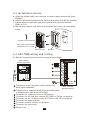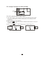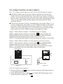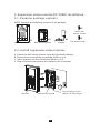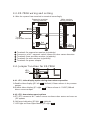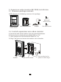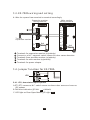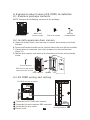
1
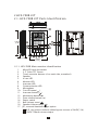
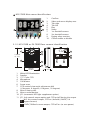
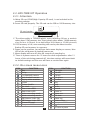
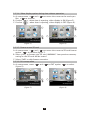
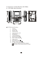
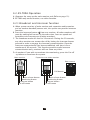
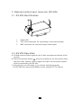
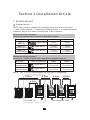
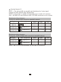
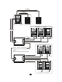
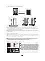
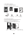
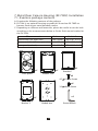
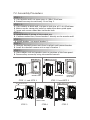
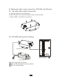
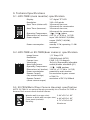
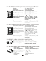
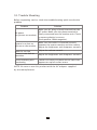
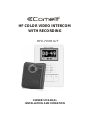
HF COLOR VIDEO INTERCOM
WITH RECORDING
HFX-700R KIT
,
OWNER S MANUAL
INSTALLATION AND OPERATION
TABLE OF CONTENTS
Section 1: User Article
1.Introduction
2.HFX-700R KIT
2.1.HFX-700R KIT Parts Identification
2.1.1.HFX-700R Main monitor identification
2.1.2.HFX-700R or EX-700D door camera identification
2.2.HFX-700R KIT Operation
2.2.1.Attention
2.2.2.On screen menu icons
2.2.3.Setup menu
2.2.3.1.Adjust clock
2.2.3.2.Door open status indication
2.2.3.3.Video or photo recording
2.2.3.4.Video display option
during door release operation
2.2.3.5.Format a new SD card
2.2.3.6.Exit setup menu
2.2.4.Intercom function operations
2.2.4.1.Push to talk function(similar to walky-talky)
2.2.4.2.Visitor calls from door camera
2.2.4.3.Zoom and pan/tilt function
2.2.4.4.Monitor doorbell cameras from main monitor
2.2.4.5.All page announcement and
intercom among monitors
2.2.5.Privacy function
2.2.6.Video/Photo playback menu
2.2.6.1.Video or photo playback
2.2.6.2.Delete video/photo section(s)
3.Expansion video monitor (EX-700H)
3.1.EX-700H Identification
3.2.EX-700H Operation
3.2.1.Visitor calls from door camera
3.2.2.Audio and video monitoring
3.2.3. Broadcast and intercom function
4.Expansion audio monitor (EX-700A)
4.1.EX-700A Identification
4.2.EX-700A Operation
4.2.1.Broadcast and intercom function
5.Optional video input converter (EX-VIN)
5.1.EX-VIN Identification
5.2.EX-VIN Operation
1
2
2
2
3
4
4
4
5
5
5
5
6
6
6
7
7
7
8
8
9
9
9
9
10
11
11
12
12
12
12
13
13
14
14
15
15
15
Section 2: Installation Article
16
1. System layout
19
2. Read before installation
20
3. HFX-700R installation
20
3.1.Examine package contents
20
3.2.Install main monitor
21
3.3.Install door camera
21
3.4.HFX-700R wiring and setting
22
3.5.Jumper function on main monitor
22
3.5.1.JP1, external doorbell trigger options
23
3.6.Jumper function on door camera
23
3.6.1.JP1, door control options and
CCD on/off during the output
23
3.6.2.JP2, light senor options
24
4. Expansion video monitor(EX-700H) installation
24
4.1.Examine package contents
24
4.2.Install expansion video monitor
25
4.3.EX-700H wiring and setting
25
4.4.Jumper function on EX-700H
4.4.1.JP1, video display option during door release operation 25
25
4.4.2.JP2, door status report options
26
5. Expansion audio monitor(EX-700A) installation
26
5.1.Examine package contents
26
5.2.Install expansion audio monitor
27
5.3.EX-700A wiring and setting
27
5.4.Jumper function on EX-700A
27
5.4.1.JP2, door status report options
28
6. Expansion door camera (EX-700D) installation
28
6.1.Examine package contents
28
6.2.Install expansion door camera
28
6.3.EX-700D wiring and setting
29
7. Metal door camera housing (EX-700V) installation
29
7.1.Examine package contents
30
7.2.Assembly procedure
31
8. Optional video input converter (EX-VIN) installation
31
8.1.Install video input converter
31
8.2.EX-VIN wiring and setting
32
9. Technical specifications
34
10.Trouble shooting
Section 3: Appendix
Section 1:User Article
1. Introduction
Thank you for purchasing this Video Intercom System. This advanced
system not only allows you to identify and communicate with visitors at
the door and allows for remote door strike release, it can also record the
video intercom communication on a micro SD card for later playback.
This system has an interactive on screen menu for easy operation by
touch sensitive buttons located on the two sides of the screen. Please
read thru this manual for all detailed functions.
This package consists of a main monitor and a doorbell camera unit and
a power supply.
This intercom system is capable of expanding up to a maximum of 4
indoor monitors and 2 doorbell cameras in a standard system. With
additional EX-HUB home-run expansion modules, the total number of
monitors can be extended up to 8 total.
For more information regarding the complete line of our products,
please visit www.comelitusa.com
1
2.HFX-700R KIT
2.1. HFX-700R KIT Parts Identification
1
2
3
17
178mm
(7.0 )
15
14
7
8
36mm
(1.42 )
6
4 16
5
9
10 11 12 13
118mm
(4.65 )
2.1.1. HFX-700R Main monitor identification
1.
Micro SD card slot socket
2.
3.5" Color TFT Screen
3.
Touch sensitive buttons (4 on each side, unmarked)
4.
Speaker
5.
In use LED
6.
Monitor LED
7.
Intercom LED
8.
Communication LED
9.
Microphone
10. Cut-off button( )
11. Intercom button( )
12. Monitoring button( )
13. Door release button( )
14. Power switch
15. Bell Volume tuner( )
16. Speaker Volume tuner( )
17. JP1, external doorbell trigger option
N.O. dry contact (default) (allow bypass current of 24VDC/1A)
12VDC150mA current output
2
HFX-700R Main menu identification:
1.
2.
3.
4.
5.
6.
7.
8.
9.
10.
1
2
4
3
5
6
7
8
9
10
Confirm
Video and menu display area
Tab right
Tab left
Play
Setup
1st doorbell camera
2st doorbell camera
Paging other monitor
Chime enable or disable
2.1.2. HFX-700R or EX-700D Door camera identification
1
7
3
4
130mm
(5.12")
JP2
1
2
5
2
8
JP1
10
3
4
11
9
6
98mm
(3.86")
36mm
(1.42")
1.
2.
3.
4.
5.
6.
7.
White LED Illumination
Speaker
1/3" Color CCD
Microphone
Call button
Screw cover
CCD vertical view angle adjustment dial
(-6 degrees, 0 degrees, 8 degrees, 16 degrees)
8. Wire to door strike
9. Wire to main Monitor
10. JP 2 (automatic LED light supplement option)
11. JP1, lock control output option and CCD on/off during the output
N.O. dry contact output; CCD on. (default) (24VDC/1A
bypass current)
12VDC/300mA current output; CCD off to. (to save power)
3
2.2. HFX-700R KIT Operation
2.2.1. Attention
A. Micro SD card, SDHC(High Capacity SD card), is not included in this
product package.
B. Insert SD card properly. The SD card can be 2GB to 16GB memory size.
HC 4
i cro
mS
SD card socket
C. The video quality is 720x480 pixels, every recording (20 sec. a section)
takes about 15M memory size. Every photo takes about 130KB memory
size (So for a 4 GB card, it can hold about 260 Videos or 25,000 pictures).
D. If SD memory is full, new recording will overlay the oldest section.
Backup SD card memory is necessary.
E. Power on the machine, you will see main menu display on screen, blue
LED of the call button at doorbell camera on.
F. Menu display will turn off after 90 seconds of standing by.
G. There is a power reserve for 12 hours for clock adjustments. after 12
hours of the unit being powered off, the time settings will revert back
to default settings and the user will have to set the time again.
2.2.2. On screen menu icons
ICON
FUNCTION
Play
Setup
1st doorbell camera
2nd doorbell camera
Paging other monitor
Chime
Chime disable
Set clock
Door status-BELL
Door status-LED
Video recording mode
photo recording mode
DR Release Video ON
DR Release Video OFF
Format SD card
Escape to MAIN menu
ICON
4
SD
FUNCTION
Tab right
Tab left
Tab up
Tab down
Confirm
Play
Stop
Pause
Record
Zoom in
Zoom out
Tilt view
Video log
Delete video
Escape to MAIN menu
Off
SD card in place
2.2.3. Setup menu
A. Move cursor to SETUP icon
at main menu;
B. Press
can enter setup menu.
2.2.3.1. Adjust clock
A. At setup menu,
and
can move the cursor;
can alter parameter (figure 1);
B.
can save your new setup.
and
2.2.3.2. Door open status indication
A. There are PT1 and PT2 terminals on main monitor for connection of a
magnetic switch to detect door open status.
(magnetic switch is not included in the package)
B. At setup menu,
and
can move the cursor to the mode you
like;
can save your setup (figure 2).
C. If select
, when door is opening, the main monitor will make a
chime indication; If select
, when door is opening, the LED of
the main monitor's door release button will turn ON.
2010/12/08
15:29:30
YY/MM/DD
Set Time/Date
15:30
Door Status Chime
VX.X.X(xxxxxx)
15:30
VX.X.X(xxxxxx)
(figure 1)
(figure 2)
2.2.3.3. Video or photo recording
A. At setup menu,
and
can move the cursor to the mode
you like;
can save your setup.
B. If select
, enable automatic video recording mode, 20 seconds
a section, when visitor calls from doorbell camera (figure 3).
C. If select
, enable automatic photo recording mode, 3 shots per
action, when visitor calls from doorbell camera (figure 4).
Video
15:30
Photo 3
VX.X.X(xxxxxx)
(figure 3)
15:30
VX.X.X(xxxxxx)
5
(figure 4)
2.2.3.4. Video display option during door release operation
A. At setup menu,
and
can move the cursor to the mode you
like;
to confirm.
B. If select
, when door is opening, video display is ON (figure 5).
C. If select
, when door is opening, video display is OFF (figure 6).
DR Release Video ON
15:30
DR Release Video OFF
VX.X.X(xxxxxx)
15:30
VX.X.X(xxxxxx)
(figure 5)
(figure 6)
2.2.3.5. Format a new SD card
A. At setup menu,
and
can move the cursor to SD card format
option;
to confirm (figure 7).
B. Select YES to format your SD card, WARNING: Your previous memory
saving on the SD card will be erased.
C. Select NO to skip format execution.
2.2.3.6. Exit setup menu
A. At setup menu, move
(figure 8)
and
to EXIT option;
to select.
Format
YES
NO
Format SD Card
15:30
Exit
VX.X.X(xxxxxx)
15:30
VX.X.X(xxxxxx)
(figure 7)
(figure 8)
6
2.2.4. Intercom function operations
2.2.4.1. Push to talk function(similar to walky-talky)
A. Communication LED on means voice is free to go out from monitor to
door camera.
B. During the conversation, press the Monitor Button
for 2 seconds to
switch to push-to-talk mode. In this mode, pressing the Monitor Button
(Communication LED will turn on) will activate the one-way voice
communication to the door camera; releasing the Monitor Button
and (Communication LED turns off )allows for one-way voice
communication to come in from the door camera to the monitor.
C. This function can be useful when the environment at door camera side
becomes too noisy.
2.2.4.2. Visitor calls from door camera
A. Typical video intercom function, when call button is triggered, all
monitors will chime and monitors will turn on.
B. In 3 seconds time, the main monitor begins to record video of the door
camera. In 20 seconds time if there is no answer from monitor, the
system will time out. Visitor's video is recorded (figure 1).
C. If tenant answers from main monitor (pressing the monitor button
),
video recording continues for 20 seconds, conversation time is limited
to 90 seconds.
D. If tenant answers visitor call from expansion monitor, main monitor will
cutoff, video recording will stop pre maturely.
E. Pressing the door release button
to control door strike; pressing the
cutoff button
can end the intercom operation.
7
2.2.4.3. Zoom and pan/tilt function
A. While talking to the doorbell camera from main monitor, tenant can at
the same time operate the on-screen-menu to stop or resume video
recording.
B. To operate zoom and pan/tilt function has to stop recording first and
resume afterward. (figure 9,10,11,12)
REC
0 0 0 0 12
2010/06/28
04 57 39
SD
X
(figure 9:stop recording)
SD
2010/06/28
04 57 39
X
(figure 11
1
(figure 10 :resume recording)
2010/06/28
04 57 39
SD
3
X
zoom)
3
(figure 12: pan/tilt)
2.2.4.4. Monitor doorbell cameras from main monitor
A. From the main monitor, tenant can operate hard button to monitor
doorbell cameras or operate on-screen-menu for interactive functions
as video recording, zoom and tilt viewing angles (figure 11).
B. Monitoring doorbell camera is limited for 90 seconds before automatic
cutoff.
8
2.2.4.5. All page announcement and intercom among monitors
A. From any monitor, tenant can press intercom button
or select
the function from the on-screen main monitor menu to page and make
a nnoucements to other monitors (figure 13, 14).
B. Paging and annoucements can last for 30 seconds time, if any other
monitor press the intercom button to respond, the two monitors can
then engage in intercom conversation for maximum of 90 seconds.
SD
2010/06/28
04 5 7 39
(figure 13)
(figure 14)
2.2.5. Privacy function
A. Move and select the BELL icon
on the main menu.
B.
means privacy off (chime on);
means privacy on and the
chime is disabled.
2.2.6. Video/Photo playback menu
A. Move and select PLAYBACK icon
from main menu can play the
latest video/photo recorded.(figure 15).
2.2.6.1. Video or photo playback
A. Select playback icon on main menu will firstly play the latest
video/photo recorded.
B. Video and photo are stored on the same file logs. Playback will show
(
) or (
) on the up left corner.
C. Select
to search all video /photo by picture frames of the date.
D. Select
to search video FILES by date log(figure 16 and 17).
E. Select
to playback;
to pause;
to stop(figure 18).
F. Select
can return to main menu.
9
10062800
/100401-1
1 01224 00
10/06/28
04 57 39
(figure 15)
(figure 16)
2010/06/28
04 5 7 3 9
1 0 / 1 2/ 0 8
04 57 39
10120800
/1 1 2 6 5 5 - 1
(figure 17)
(figure 18)
2.2.6.2. Delete video/photo section(s)
A. Select
to enter delete sub menu. (figure 19).
B. Move and select delete by SINGLE video section or ALL video sections.
C. Reconfirm YES or NO for the action (figure 20).
D. Select EXIT to move to PLAYBACK menu; Select
to return to
main menu.
Delete
File Del ete
Si ngle
All
Cancel
YES
NO
Door release button
Monitoring button
Intercom button
(figure 19)
(figure 20)
10
3. Expansion Video Monitor (EX-700H)
3.1. EX-700H Identification
EX-700H
13
1 14
178mm
(7.0 )
12
5
6
36mm
(1.42 )
4
17
18
15
2 16
3
7
8
9
10 11
118mm
(4.65 )
EX-700H identification:
1.
3.5" Color TFT Screen
2.
Speaker
3.
In use LED
4.
Monitor LED
5.
Intercom LED
6.
Communication LED
7.
Microphone
8.
Cut-off button( )
9.
Intercom button( )
10. Monitoring button( )
11. Door release button( )
12. Power switch
13. Brightness tuner( )
14. Sharpness tuner( )
15. Bell Volume tuner( )
16. Speaker Volume tuner( )
17. JP1, video display option during door release operation
Enable video display (JP1 left) (default)
Disable video display (JP1 right)
18. JP2, door status report option
Bell tone indication (JP2 left) (default)
LED light on Door Open Button (JP2 right)
11
3.2. EX-700H Operation
3.2.1. Visitor calls from door camera
A. When the Call button on the camera is pressed, All monitors on the
system will ring with a chime sound and all monitors will be activated.
B. After the call, if nothing on the monitor is pressed, the system will time
out after 30 seconds. If the monitor button
is pressed, the system
will stay active for 90 seconds.
C. You are able to terminate the activity on the monitor at any time by
pressing the Cut-off button
.
D. Press door release button
from monitor can release remote door
strike at door camera.
3.2.2. Audio and video monitoring
A. Pressing the monitor button
will turn on the audio and video from
door camera.
B. If there is a second door camera on this system, pressing the Monitor
button
again will scroll the image to the second expansion door
camera.
C. At anytime if you wish to terminate the monitoring, press the Cut-off
button
to terminate the system.
3.2.3.Broadcast and intercom function
A. When system consists of main monitor and expansion monitor and an
outdoor doorbell/camera unit, the system can provide intercom function.
B. Press the intercom button
from any monitor, all other monitors will
react by making bell sound. At the same time, host can speak and
broadcast voice message to all other monitors.
C. The broadcast mode can last for 20 seconds. During the 20 seconds,
any other monitor can answer the call by having the intercom button
pressed in order to engage the intercom communication. Once the
intercom communication has been established, talk time is for a
maximum of 90 seconds. This function provides audio intercom
communication only, monitors will not show any video.
D. At anytime if you wish to terminate the monitoring, press the Cut-off
button to terminate the system.
12
4. Expansion Audio Monitor (EX-700A)
4.1. EX-700A Identification
14
178mm
(7.0 )
11
4
5
36mm
(1.42 )
3
12
1 13
2
6
7
8
9
10
118mm
(4.65 )
EX-700A identification:
1.
Speaker
2.
In use LED
3.
Monitor LED
4.
Intercom LED
5.
Communication LED
6.
Microphone
7.
Cut-off button( )
8.
Intercom button( )
9.
Monitoring button( )
10. Door release button( )
11. Power switch
12. Bell Volume tuner( )
13. Speaker Volume tuner( )
14. JP2, door status report option
Bell tone indication (JP2 left) (default)
LED light on Door Open Button (JP2 right)
13
4.2. EX-700A Operation
A. Operates the same as the main monitor unit (Refer to page 12).
B. EX-700A only audio function, not video function.
4.2.1.Broadcast and intercom function
A. When system consists of main monitor and expansion audio monitor
and an outdoor doorbell/camera unit, the system can provide intercom
function.
B. Press the intercom button
from any monitor, all other monitors will
react by making bell sound. At the same time, host can speak and
broadcast voice message to all other monitors.
C. The broadcast mode can last for 20 seconds. During the 20 seconds,
any other monitor can answer the call by having the intercom button
pressed in order to engage the intercom communication. Once the
intercom communication has been established, talk time is for a
maximum of 90 seconds. This function provides audio intercom
communication only, monitors will not show any video.
D. At anytime if you wish to terminate the monitoring, press the Cut-off
button to terminate the system.
Main monitor
Expansion non-video monitor
Door camera
Call button
Door release button
Monitoring button
Intercom button
Cut-off button
Door release button
Monitoring button
Intercom button
Cut-off button
14
5. Optional video input converter (EX-VIN)
5.1. EX-VIN Identification
1
1.
2.
3.
2
3
Power LED
The 2-wire terminals for connecting to the main monitor
BNC connector for external camera video input
5.2. EX-VIN Operation
A. EX-VIN converts video signal on the 2-wire transmission format of the
system.
B. Press the monitor button
from any monitor to see the camera from
the main door camera, press it again to scroll to the external camera
device connected to the EX-VIN.
C. Pressing the cut-off button
to exit the monitoring mode.
* The EX-VIN does not provide power to the external CCTV Camera
15
Section 2:Installation Article
1. System layout
System layout 1:
NOTE: the system is capable of expanding up to a total of 4 monitors
(1 main video monitor + 3 expansion video monitors or 3 expansion audio
monitors (any mix of video or audio) and 2 door cameras.
Maximum w iring distance
(using dry contact lock control at doorbell camera)
Wire type
Wire assignment
CAT-5
AWG#24
AWG#22
parallel wires
AWG#18
parallel wires
} Signal wires
Signal wires
Signal wires
A Max
B Max
100m
(328 feet)
100m
(328 feet)
100m
(328 feet)
100m
(328 feet)
100m
(328 feet)
100m
(328 feet)
Maximum w iring distance
(using the 12VDC/300mA lock control at doorbell camera)
Wire type
Wire assignment
AWG#22
parallel wires
AWG#18
parallel wires
Signal wires
Signal wires
A Max
B Max
50m
(164 feet)
100m
(328 feet)
50m
(164 feet)
100m
(328 feet)
NOTE : CAT-5 is not recommended for this type of installation.
A Max
B Max
B Max
B Max
A Max
EX-700D
HFX-700R KIT
EX-700H or EX-700A
16
System layout 2:
NOTE 1: The wiring HUB can amplify and distribute the 2-wire signal
among the main monitor and sub-monitors.
NOTE 2: the system is capable of expanding up to a total of 5 monitors
with 1 EX-HUB or 8 total monitors with 2 EX-HUBs connected in one system.
Maximum wiring distance
(using dry contact lock control at doorbell camera)
Wire type
CAT-5
AWG#24
AWG#22
parallel wires
AWG#18
parallel wires
Wire assignment
} Signal wires
Signal wires
Signal wires
A Max
B Max
C Max
100m
100m
100m
(328 feet) (328 feet) (328 feet)
100m
100m
100m
(328 feet) (328 feet) (328 feet)
100m
100m
100m
(328 feet) (328 feet) (328 feet)
Maximum w iring distance
(using the 12VDC/300mA lock control at doorbell camera)
Wire type
AWG#22
parallel wires
AWG#18
parallel wires
Wire assignment
A Max
B Max
C Max
50m
50m
100m
(164 feet) (164 feet) (328 feet)
100m
100m
100m
(328 feet) (328 feet) (328 feet)
Signal wires
Signal wires
NOTE : CAT-5 is not recommended for this type of installation.
17
A Max
A Max
HFX-700R
EX-700D
EX-700H or EX-700A
B Max
C Max
EX-HUB
OUT1
IN
OUT2
POWER
OUT3
POWER LED
OUT4
EX-700H or EX-700A
NOT E 1:OUT4 can also be
used to connect to a expansion
monitor.
NOT E 2:wiring distance<300ft.
EX-HUB
OUT1
IN
OUT2
POWER
OUT3
POWER LED
C Max
OUT4
C Max
EX-700H or EX-700A
18
2. Read before installation
Main monitor
Proper height:
Door camera
View Angle:
70cm
(27.6")
170cm
(66.9")
100cm
(39.3")
165cm
(64.9")
50cm(19.7 ")
50cm(19.7 ")
The proper height of monitor or door camera is 160~170cm(63"~67")
from the ground. This may vary on each installation. View range should
be actively tested before complete.
Viewing window of door camera is about 70cm up-n-down, and 100cm
left-n-right.
NOTE 1: Wiring distance
From main monitor to door camera: Maximum of 164 feet with AWG22
normal 2-wire parallel wires. Maximum of 328 feet with AWG18 normal
2-wire parallel wires or CAT-5 cable.
From monitor to monitor (every section): Maximum of 328 feet with
AWG22normal 2-wire parallel wires or CAT-5 cable.
NOTE 2: the installation environment
Please avoid installation in an enclosed
environment as this may cause feedback.
Please avoid installation in direct sunlight
as this can cause a blurry picture or dark
shadows on subjects facing the camera.
Please avoid wire installation near other
power or signal lines and avoid placing
units close to high power appliances as
this may cause audio/video interference.
19
3. HFX-700R installation
3.1. Examine package contents
NOTE: Examine the following contents of the package.
PT1
PT2
DG1
HF COLOR VIDEO INTERCOM
WITH RECORDING
DG2
OUT +
OUTDR2
DR1
<+ >
P O WE R
<->
X1
Wall mount bracket
HFX-7 00R KI T
X1
X1
Main monitor
Door camera
X1
Adaptor
X4
,
OWN E RS MA N UA L
IN ST AL LA TION AN D OP E RAT ION
Manual
X4
White wall
mount screws
Flat head screws
X1
X1
security
screw wrench
3.2. Install main monitor
A. Fasten the wall mount bracket using the provided hardware.
B. Fasten wires on terminals accordingly (Refer to 3.4).
C.Select jumpers for desired function (Refer to 3.5).
C. Plug-in pin wires and mount the monitor unit on bracket.
Monitor
Wall mount bracket
20
Do not plug in the
pow er at this stage.
3.3. Install door camera
A. Open the hidden latch, and unscrew to remove door camera unit from
bracket.
B. Fasten wall mount bracket to the surface where the unit will be installed.
C. Fasten wires on terminals and select jumpers for desired function.
(Refer to 3.6)
D. Mount door camera unit back on the bracket and secure the assembly
screw.
security screw wrench
Pull out screw cover
to access the screw
Door camera
Bracket
3.4. HFX-700R wiring and setting
A. Wire the system from terminal to terminal accordingly.
door camera
Wiring terminal
1
8
9
1
7
JP2
2
JP1
3
PT1
PT2
2
DG1
3
OUT+
DG2
OUT-
4
4
DR2
DR1
<+>
POWER
<->
1
2
3
4
5
6
7
8
9
5
Red 6
Black
Connect to a N.C. magnetic switch sensor for
Main monitor
door status detection
Wiring terminal
Trigger a N.O. external chime or strobe light which
is synchronized with door bell trigger
Terminals for expansion monitor (w/polarity)
Terminals for the 2nd door camera (EX-700D) or EX-VIN (no polarity)
Terminals for the 1st door camera (EX-700D) or EX-VIN (no polarity)
Terminals for power adapter
Terminals to main monitor (no polarity)
Terminals for door strike
Electric Lock
21
3.5. Jumper function on main monitor
JP1
3.5.1. JP1, external doorbell trigger options
A. DG1/DG2 trigger a N.O. device to synchronize with doorbell trigger
and react as JP3 options. Wrong setting may cause damage to the
equipment.
B. DG1(+) and DG2(-) have polarity.
C. JP3 on left(
) for N.O. dry contact (default) (allow bypass current of
24VDC/1A) (figure 1).
D. JP3 on right(
) for 12VDC150mA current output (figure 2).
POWER
AC24V or
DC24V 1A
External chime
External chime
DG1
DG2
[Figure 1]
DG1
DG2
[Figure 2]
22
3.6. Jumper function on door camera
3.6.1. J P1, door control options and CCD on/off during the output
Each Door Camera on the system is able to operate and release one
electric lock. On a full system with 2 door cameras, the user is able to
release up to two electric locks. The system can only release one electric
lock at a time, depending on which door camera the call originated from.
There are two door release wiring options that work with the Video
Intercom System.
The system can either provide a normally open dry contact (figure 1), or
can be configured to give power (12V DC 300mA) straight to an electric
lock that is within the power requirements (figure 2). If you are using
power from the system (figure 2), It is necessary to use an electric lock
that requires less than 300mA of power to engage the strike.
Figure 1: Door Release Option 1 (Additional power supply)
NOTE 1: When jumper setting is on the left (
)(factory setting), the
DOOR RELEASE terminals provide as N.O. dry contact, with no polarity
allowing maximum by-pass current of AC24V or DC24V 1A.
NOTE 2: This option will keep the video on during the release of the strike.
Figure 2: Door Release Option 2 (Using pow er from the system)
NOTE 1: When jumper setting is on the right(
), the DOOR RELEASE
terminals provide current output of maximum 12VDC/300mA.
NOTE 2: This option will cut CCD power during the operation and there
will be a momentary loss of video upon release of the strike.
Door camera
JP2
1
2
JP1
JP2
3
4
JP1
Electric Lock
Door camera
Power for Lock
12/24V DC
1 Amp Max
Electric Lock
[Figure 1]
[Figure 2]
3.6.2. J P2, light senor options
A. Factory setting is left(
) which enables automatic LED illumination at
in low lighting conditions.
B. Select and plug JP2 to its right(
) to disable LED illumination of the
doorbell camera at all times.
23
4. Expansion v ideo monitor(EX-700H) Installation
4.1. Examine package contents
NOTE: Examine the following contents of the package.
X2
White wall
mount screws
PT1
PT2
OUT +
OUTIN+
IN-
<+ >
P O WE R
<->
X1
Expansion monitor
Wall mount bracket
X2
X1
X1
Adaptor
Flat head screws
4.2. Install expansion video monitor
A. Fasten the wall mount bracket using the provided hardware.
B. Fasten wires on terminals accordingly (Refer to 4.3).
C. Select jumpers for desired function (Refer to 4.4).
C. Plug-in pin wires and mount the monitor unit on bracket.
Monitor
Wall mount bracket
24
Do not plug in the
pow er at this stage.
4.3. EX-700H w iring and setting
A. Wire the system from terminal to terminal accordingly.
Expansion monitor
Main monitor
wiring terminal
Wiring terminal
PT1
2
PT1
PT2
PT2
DG1
OUT+
4
OUTIN+
To next
expansion monitor
DG2
OUT+
3
OUT-
1
INDR2
<+>
POWER
<->
Red 5
Black
DR1
<+>
POWER
<->
Red
Black
1 Terminals for expansion monitor (w/polarity)
2 Connect to a N.C. magnetic switch sensor for door status detection
3 Terminals from previous monitor (w/polarity)
4 Terminals for next monitor (w/polarity)
5 Terminals for power adapter
4.4. J umper function for EX-700H
JP1
JP2
4.4.1. JP1, video display option during door release operation
A.Enable video display (JP1 left
output.
B.Disable video display (JP1 right
direct current output
) (default) if door release is dry contact
) if door release is 12VDC/300mA
4.4.2. JP2, door status report options
A.PT1/PT2 connect a N.C. switch sensor to detect door status and react as
JP2 options
B. Bell tone indication (JP2 left
) (default)
C. LED light on Door Open Button (JP2 right
)
25
5. E xpansion audio monitor(EX-700A) Installation
5.1. Examine package contents
NOTE: Examine the following contents of the package.
X2
White wall
mount screws
PT1
PT2
OUT +
OUTIN+
IN-
<+ >
P O WE R
<->
X1
Expansion
audio monitor
X1
X1
Wall mount bracket
Adaptor
X2
Flat head screws
5.2. Install expansion non-video monitor
A. Fasten the wall mount bracket using the provided hardware.
B. Fasten wires on terminals accordingly (Refer to 5.3).
C. Select jumpers for desired function (Refer to 5.4).
D. Plug-in pin wires and mount the monitor unit on bracket.
Monitor
Wall mount bracket
26
Do not plug in the
pow er at this stage.
5.3. EX-700A w iring and setting
A. Wire the system from terminal to terminal accordingly.
Expansion monitor
wiring terminal
Main monitor
Wiring terminal
PT1
2
PT1
PT2
PT2
DG1
OUT+
4
OUTIN+
To next
expansion monitor
OUT+
OUT-
1
INDR2
<+>
POWER
<->
1
2
3
4
5
DG2
3
Red 5
Black
DR1
<+>
POWER
<->
Red
Black
Terminals for expansion monitor (w/polarity)
Connect to a N.C. magnetic switch sensor for door status detection
Terminals from previous monitor (w/polarity)
Terminals for next monitor (w/polarity)
Terminals for power adapter
5.4. J umper function for EX-700A
JP2
5.4.1. JP2, door status report options
A.PT1/PT2 connect a N.C. switch sensor to detect door status and react as
JP2 options
B. Bell tone indication (JP2 left
) (default)
C. LED light on Door Open Button (JP2 right
)
27
6. Expansion door Camera (EX-700D) Installation
6.1. Examine package contents
NOTE: Examine the following contents of the package.
X2
X1
White wall
mount screws
Door Camera
X2
X1
security
screw wrench
Flat head screws
6.2. Install expansion door camera
A. Open the hidden latch, and unscrew to remove door camera unit from
bracket.
B. Fasten wall mount bracket to the surface where the unit will be installed.
C. Fasten wires on terminals and select jumpers for desired function.
(Page 23)
D. Mount door camera unit back on the bracket and secure the assembly
screw.
Screws wrench
Pull out screw cover
to access the screw
Door camera
Bracket
6.3. EX-700D wiring and setting
EX-700D wiring terminal
PT1
PT2
3
4
DG1
2
JP2
DG2
OUT+
1
2
JP1
3
4
OUTDR2
1
DR1
1
2
3
4
Terminals for EX-700D door camera
Terminals for main monitor DR2 terminals
Terminals for door strike
Electric Lock
28
<+>
POWER
<->
Red
Black
Main monitor
wiring terminal
7. Metal Door Camera Housing (EX-700V) Installation
7.1. Examine package contents
A. Examine the following contents of the package.
B. EX-700V is an optional housing assembly kit to enclose EX-700D to
become flush mount metal doorbell camera.
C. Depending on different wall materials, please be careful to cut the hole
according to the measurements below to fit the flush mount bracket for
the EX-700V.
Measurements
Unit:mm
Unit:inch
100x150x41 3.94"x5.91"x1.62"
Wooden wall (cut open size)
Cement or brick wall (cut open size) 114x165x49 4.49"x6.50"x1.93"
Front panel (outlook)
120x180x7 4.72"x7.08"x0.28"
x1
x1
x1
Front panel
Bracket 1
Rubber seal
x4
4.5 x10mm Screw
x6
3.0 x6mm Screw
x1
x1
Bracket 2
x1
Embed box
29
Screw wrench
7.2. Assembly Procedure
STEP 1-1 :
A. If on wooden wall, cut open space is 100x150x41mm.
B. Embed box may not necessary. Go to Step 2.
STEP 1-2 :
A. If on cement or brick wall, cut open a hole size of 114x165x49mm.
B. Make sure the stamp wire outlet on embed box been pried open.
C. Insert and secure embed box inside the hole.
STEP 2 :
A. Install bracket 2 on top of the embed box.
B. If without embed box, fasten bracket 2 directly on the wooden wall.
STEP 3 :
A. Install bracket 1 on top of bracket 2.
STEP 4 :
A. Remove doorbell camera unit from its plastic wall mount bracket.
B. Install the doorbell camera unit on top of bracket 1.
STEP 5 :
A. Place rubber seal and speaker cover on position of the front panel.
B. Fasten safety screws by using the attached wrench.
3.0 x6mm Screw
Bracket 2
Bracket 2
wooden wall
STEP 1-1 and SETP 2
STEP 3
Cement or
brick wall
STEP 1-2 and SETP 2
4.5 x10mm Screw
3.0 x6mm Screw
Bracket 1
Embed box
doorbell
camera unit
STEP 4
30
front panel
STEP 5
8. Optional video input converter (EX-VIN) Installation
8.1. Install video input converter
A. Package contains no accessories.
B. Wire EX-VIN to the video distribution box of the camera
C. Plug in BNC, no setting is necessary
8.2. EX-VIN wiring and setting
3
PT1
2
PT2
DG1
DG2
OUT+
OUT-
EX-VIN wiring terminal
DR2
1
DR1
<+>
POWER
<->
Red
Black
Main monitor
wiring terminal
CCD camera
1 2-wire terminals on EX-VIN
2 DR1 or DR2 terminals on main monitor
3 BNC for camera video
31
9. Technical Specifications
9.1. HFX-700R (main monitor) specification
3.5" digital TFT-LCD
320 x 240 pixels
30 seconds time out;
90 seconds for conversation
Auto Timer (intercom):
30 seconds time out;
90 seconds for conversation
Operating Temperature: 14 ~ 140 , indoor
Dimensions (w/ bracket): 4.65"(L) x 7.0"(W) x 1.42"(D)
input 100~240VAC 50/60Hz;
Power adaptor:
output 23VDC/1A(24W),
external
standby 3.5W, operating 11.0W
Power consumption:
(maximum)
Display:
Resolution:
Auto Timer (visitor call):
9.2. HFX-700R or EX-700D(door camera) specification
Image Sensor:
Resolution:
Camera Lens:
View Angle:
Auto Light Sensor:
Operating Temperature:
Dimensions (w/ bracket):
Power consumption:
Remote Control:
(dry contact bridge)
Remote Control:
(direct current output)
1/3" Sharp CCD
250,000 pixels (NTSC)
F/NO: 2.0 (120 degree)
-6 ,0 ,8 ,16 manually adjustable
enable/disable selectable (JP1)
-13 ~ 140 , outdoor
3.86"(L) x 5.12"(W) x 1.42"(D)
powered by main monitor
for maximum by pass current
of 24V/1A
maximum of DC12V/300mA
9.3. EX-700V( Metal Door Camera Housing ) specification
NOTE: EX-700V is an optional housing assembly kit to enclose EX-700D to
become flush mount metal doorbell camera.
Wooden wall (cut open size) :
3.94"x5.91"x1.62"
Cement or brick wall (cut open size): 4.49"x6.50"x1.93"
Front panel (outlook):
4.72"x7.08"x0.28"
Housing :
Aluminum
32
9.4. EX-700H(optional expansion monitor) specification
3.5" digital TFT-LCD
320 x 240 pixels
30 seconds time out;
90 seconds for conversation
30 seconds time out;
Auto Timer (intercom):
90 seconds for conversation
Operating Temperature: 14 ~ 140 , indoor
Dimensions (w/ bracket): 4.65"(L) x 7.0"(W) x 1.42"(D)
input 100~240VAC 50/60Hz;
Power adaptor:
output 23VDC/1A(24W),
external
standby 1.4W, operating 3.0W
Power consumption:
(maximum)
Display:
Resolution:
Auto Timer (visitor call):
9.5. EX-700A(optional non-video monitor) specification
Auto Timer (visitor call):
30 seconds time out;
90 seconds for conversation
Auto Timer (intercom):
30 seconds time out;
90 seconds for conversation
Operating Temperature: 14 ~ 140 , indoor
Dimensions (w/ bracket): 4.65"(L) x 7.0"(W) x 1.42"(D)
Power adaptor:
input 100~240VAC 50/60Hz;
output 23VDC/1A(24W),
external
Power consumption:
standby 1.4W, operating 3.0W
(maximum)
9.6. EX-VIN (video converter ) specification
Operating Temperature: -4 F ~ 140 F, outdoor
Dimensions (w/ bracket): 3.8"(L) x 2.5"(W) x 0.97"(D)
Power consumption:
powered by main monitor
9.7. EX-HUB (Home Run Configuration HUB) specification
Power Input :
Power consumption :
Operating Temperature:
Storage temperature :
Weight :
Dimensions :
Housing :
33
DC23V ~ DC24V
Standby 1.8W; Operating 2W
-4 ~140
-13 ~158
0.5 lbs
3.90"x3.19"x0.71"
Metal
10. Trouble Shooting
Before requesting service, check the troubleshooting quide to solve the
problem.
Problem
Solution
No power
(no picture on monitor)
Make sure AC plug is firmly inserted into the
AC outlet. Make sure the power terminal is
firmly connected into the monitor unit. Check
to ensure polarity is correct.
(Red=positive, Black=negative).
System is on but no
picture on the monitor
Make sure the cable is cnnected securely
between the master monitor and the camera.
Adjust the brightness and sharpness controls.
Sound is too low
Adjust the volume control.
Picture is too dark or
too white
Adjust the brightness and sharpness controls.
Video recording NOT
functioning
Check if SD card is in place and SD card icon
appears on up left screen menu.
NOTE: Be sure to use this product with the AC adapter supplied
by the manufacturer.
34
Section 3:Appendix
APPENDIX 1: WARNING
WARNING: TO REDUCE THE RISK OF FIRE OR ELECTRIC
SHOCK, DO NOT EXPOSE THE MONITOR OR POWER
ADAPTER TO WATER OR MOISTURE.
CAUTION: DO NOT OPEN. RISK OF ELECTRICAL SHOCK.
CAUTION! TO REDUCE RISK OF ELECTRICAL SHOCK, DO NOT
REMOVE COVER OR BACK, NO USER SERVICEABLE PARTS
INSIDE, REFER SERVICING TO QUALIFIED SERVICE PERSONNEL.
OTH ER WARNINGS
Monitor is designed for indoor use only. Do not install outdoors.
Keep the equipment dry. If water should get in,wipe off immediately.
Water contains minerals that can erode electronic circuits.
Intercom system is not operational during a power failure .
Intercom system may be affected by radio frequency interference or
EMI(electrical magnetic interference) in areas where broadcasting
station antennas are close by.
Keep all wiring at least 1 foot away from fluorescent lighting, dimmer
switches and AC power.
E XPLANATION OF TWO SY MB OLS
The lighting flash with arrowhead symbol, within an equilateral
triangle, is intended to alert the user to the presence of
uninsulated "dangerous voltage" within the product's enclosure
that may be of sufficient magnitude to constitute risk of
electrical shock to persons.
The exclamation point within an equilateral triangle is intended
to alert the user to the presence of important operating and
maintenance (servicing) instructions in the literature
accompanying the appliance.
35
APPENDIX 2: IMPORTANT SAFETY INSTRUCTIONS
WARNING: TO RE DUCE TH E RISK OF FIRE OR E LECTRIC
SHOCK , DO NOT E XPOSE THE MONITOR OR POW ER
ADAP TER TO WATE R OR MOIST URE .
Read Instructions -All the safety and operating instructions should be
read before operating this equipment. These instructions should be
retained for future reference.
Heed Warnings - All warnings on the equipment and in the operating
instructions should be adhered to. All instructions regarding care and
operation of this equipment should be followed.
Power Sources - Equipment should only be connected to the power
supply specified in the operating instructions or as marked on the
equipment.
Power Cord Protection-Keep cable cords and plugs clear off other
objects, particularly at the point where they exit the equipment.
Cleaning - Clean the equipment by wiping with a soft cloth (do not use
any abrasive agents or water).
Non-use Periods - Power cords should be unplugged from the outlet
when left unused for a long period of time.
Object and Liquid Entry - Take care not to drop objects or liquids on
any part of the equipment.
Damage Requiring Service -The unit should be serviced by a qualified
service personnel when:
- The power supply cord or the plug has been damaged or
- Objects have fallen, or liquid has been spilled onto the equipment or
- The equipment has been exposed to rain or
- The equipment does not appear to operate normally or exhibits
a marked change in performance or
- The equipment has been dropped and/or the enclosure has been
damaged.
Servicing - Do not attempt to service the appliance beyond that
described in the operating instructions. All other servicing should be
referred to as Qualified Distributor's Service Personnel.
36
APPENDIX 3:FCC CLASS B NOTICE
NOTE:
This equipment has been Certified and found to comply with the limits
regulated by FCC,and CE. Therefore, it is designed to provide reasonable
protection against interference and will not cause interference with other
appliance usage. However, it is imperative that the user follows this
manuals guidelines to avoid improper usage which may result in damage
to the unit, electrical shock, and fire hazard or injury. In order to improve
the feature functions and quality of the product, the specifications are
subject to change without notice from time to time.
NOTE:
This equipment has been tested and found to comply with the limits for a
Class B digital device, pursuant to Part 15 of the FCC rules. These limits
are designed to provide reasonable protection against harmful
interference in a residential installation. This equipment generates uses
and can radiate radio frequency energy and, if not installed and used in
accordance with the instructions, may cause harmful interference with
radio communications. However, there is no guarantee that interference
will not occur in a particular installaition. If this equipment does cause
harmful interference to radio or televis ion reception, which can be
determined by turning the equipment off and on, the user is encouraged to
try to connect the interference by one or more of the following measures:
-
Reorient or relocate the monitor unit
Increase the separation between the monitor and camera
Connect the equipment on a separate outlet
Consult the dealer or an experienced radio or television technician
37
APPENDIX 4:SERVICE AND WARRANTY
To receive after sales service, please provide the follow ing
information when contact.
a. Name of the product
b. Model and serial number of the product
c. The store, s name where you purchased
d. Date purchased
e. Idea and area of possible problems
Information Card
Product name
Model and serial number
,
The store s name
Date purchased (receipt)
The w arranty statements
a. This product is produced under strict internal quality control and
inspection procedures.
b. The warranty is good for one year from the date purchased.If the product
reacts down under proper treatment during warranty,please contact our
after sales connection for free-of -charge repairs.
c. The following exceptional cases will be subject to charge,even during
warranty period.
Breakdown caused by transport,or through careless treatment by customer.
Breakdown caused by unauthorized repair or modification.
Breakdown caused by natural disaster or electric power disorder.
38
http:// w w w .comelitusa.com
[email protected]