1
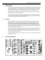
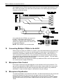
44/50 4 Zone Integrated
Mixer Amplifier
Installation & Operation Manual
Cloud Electronics Limited
140 Staniforth Road, Sheffield, S9 3HF England
Tel + 44 (0) 114 244 7051
Fax + 44 (0) 114 242 5462
E-mail [email protected]
Web site http://www.cloud.co.uk
44/50: Installation and Operation Manual
1
44/50 Integrated Four Zone Mixer Amplifier
Installation and Operation manual
Contents
Section
Page
1
Safety notes....................................................................................... 2
2
General description............................................................................ 2
3
Schematic diagram ............................................................................ 2
4
Installation ......................................................................................... 3
5
Music inputs....................................................................................... 3
6
Sensitivity & gain control.................................................................... 3
7
Music control – local or remote .......................................................... 3
8
Music equalisation ............................................................................. 3
9
Line 4 priority ..................................................................................... 4
10
Microphone inputs ............................................................................. 4
11
Paging microphone............................................................................ 4
12
Connecting Multiple CPM-4s to the 44/50 .......................................... 4
13
Microphone gain control..................................................................... 5
14
Microphone equalisation .................................................................... 5
15
High pass filter ................................................................................... 6
16
Microphone level controls .................................................................. 6
17
Microphone priority ............................................................................ 6
18
Auxiliary outputs ................................................................................ 6
19
Output details..................................................................................... 6
20
100V or 70V line operation................................................................. 6
21
Remote music mute – fire alarm interface.......................................... 7
22
Fitting and configuring the REM-4 remote control module.................. 7
23
Special notes regarding the use of the REM-4 ................................... 7
24
Music signal processing PCB............................................................. 8
25
Installing RSL-1 or RL-1 remote controls ........................................... 8
26
Controlling two or more zones with one RL-1..................................... 8
27
Controlling two or more zones with one RSL-1 .................................. 9
28
Front panel music level control defeat................................................ 9
29
Controlling the music functions using external DC control................ 10
30
EMC considerations......................................................................... 10
31
Technical specifications ................................................................... 11
32
General specifications...................................................................... 11
2
1
44/50: Installation and Operation Manual
Safety Notes
The Cloud 44/50 contains several PCB mounted jumpers which can be set to provide the
desired configuration for a specific application; these adjustments should be performed by
a technically qualified person who fully understands the hazards associated with mains
operated equipment. Do not remove the top panel unless you are qualified to do so.
Remove the power cable from the unit before removing the top panel and do not make
any adjustments with the unit switched on.
The Cloud 44/50 is supplied with a power cable fitted with a moulded plug; if the plug is
cut off the lead for any reason, remember that the discarded plug is a potential hazard
and should be disposed of in a responsible manner.
2
General
The Cloud 44/50 is a versatile, multi-source four zone mono mixer with four 50 watt
power amplifiers. The unit has applications where two microphone and four line level
music signals are required to feed four separate areas in any combination. Optional
accessories extend the flexibility of the unit: A dedicated four zone paging mic with preannouncement chime is available, a plug-in remote control PCB provides remote control
of music level and source and for line distribution systems, a four channel 100V/70V line
transformer module is also available.
The front panel controls are reduced to a minimum to reduce confusion; if preferred, the
unit can be positioned in a protected area with just the remote music level and source
controls positioned in the most appropriate location. All pre-set controls are either on the
rear panel or protected by covers.
A remote music mute facility is provided which may be used to satisfy the requirements of
the Local Fire Officer.
3
Schematic Diagram
44/50: Installation and Operation Manual
4
3
Installation
The Cloud 44/50 is suitable for mounting in a standard 19" equipment rack and occupies
two units of rack space. Sufficient ventilation should be provided particularly where it is
required to deliver a high output power for long periods of time; the unit draws cool air
through the front panel and exhausts through the rear panel. The 44/50 is 300mm deep
but a depth of 375mm should be allowed to clear connectors.
5
Music Inputs
The 44/50 operates in mono but is fitted with four stereo line inputs, which are internally
mixed to form a mono signal. The line inputs are suitable for most music sources such as
compact disc players, tape players and receivers etc. All the inputs are unbalanced and
use RCA type phono sockets. The input impedance is 47kΩ.
6
Sensitivity & Gain Control
All four line inputs have a pre-set gain control on the rear panel adjacent to the respective
input sockets. The input sensitivity can be varied from -12dBu (195mV) to +8dBu (2.0V).
The pre-set gain controls should be set so that all the input signals operate at the same
level within the 44/50 and the music level controls have an optimum range of control.
7
Music Control - Local or Remote
The music source and music level control functions can be operated from the front panel,
or remotely when the optional REM-4 plug-in four channel remote control module is fitted
and wired to a maximum of four RSL-1 control plates. This plate can be positioned up to
100 metres from the 44/50 and 2-core cable with overall screen should be used. Selfadhesive labels are provided to identify the signal source on both the 44/50 front panel
and the RSL-1. The front panel mounted music level controls can be defeated if required,
please refer to section 27 for full details. If preferred, the music source can be controlled
from the 44/50 front panel with the music level only controlled remotely using the RL-1
remote level control. See section 21 for REM-4 fitting instructions and section 24 for
remote level plate installation requirements.
8
Music Equalisation
Separate treble and bass controls are provided for music signals only on each of the four
zones. This arrangement allows the installer to optimise the response of the music
signals on a zone by zone basis where different acoustic properties require optimal
equalisation adjustment. The equalisation controls are concealed behind the removable
control panel secured to the front panel. Using the supplied Allen key, remove the four
Allen cap screws which retain the control panel; the HF and LF equalisation controls are
clearly marked and located below the music controls for the relevant zone. A flat
frequency response can be achieved by positioning the slot on the control shaft in the
horizontal plane. The music treble control (HF) has a range of ±10dB at 10kHz and the
music bass control operates with a range of ±10dB at 50Hz.
4
9
44/50: Installation and Operation Manual
Line 4 Priority
The Cloud 44/50 has a facility to allow fully automatic priority to a JukeBox or Spot
Announce Player on Zone 1 only. A priority switch (concealed behind the removable plate
on the front panel) is provided to select this facility. When the line 4 priority is in
operation, Zone 1 will operate normally until a signal is detected on line 4 upon which the
selected signal (usually background music) will mute, allowing the signal on line 4 to
operate with priority. Once the signal on Line 4 ceases, the selected music signal will
smoothly restore to its former level; the time taken for this restoration can be set at 3, 6 or
12 seconds by fitting the appropriate jumper (J5) on the upper printed circuit board. The
factory default restoration time is 3 seconds. (See PCB layout on page 7)
10
Microphone Inputs
Two microphone inputs are provided and the microphone amplifier is an electronically
balanced, transformer-less design configured for optimum low noise performance.
The input impedance is greater than 2kΩ and is suitable for microphones in the 200Ω to
600Ω range. Inputs are via gold plated 3 pin XLR type connectors with latch and these
are positioned on the rear panel. For balanced microphones, connect the cable screen to
pin 1, the in-phase signal (+Ve) to pin 2 and the reverse phase signal (-Ve) to pin 3.
For unbalanced microphones, connect a wire link from pin 1 (ground) to pin 3 inside the
XLR cable mounted plug; use pin 1 as ground (cable screen) and pin 2 as hot.
11
Paging Microphone
The Cloud CPM-4 four zone paging microphone is available as an optional accessory for
the Cloud 44/50; the unit features zone selection switches which allow paging to all four
zones in any combination and in addition, a ‘call all’ button is provided for convenient
announcements to all zones.
The paging microphone is supplied with:
• 2 cable glands to accept 2-6mm cable
• 2 cable glands to accept 4-8mm cable
• 2 grommets
• A 9-core/female sub D-type cable assembly that should be fitted to the 44/50
motherboard.
• A Sub D-type male connector
• 4 M16 Nuts
NOTE: Should you wish to order a CPM-8 for use with the 44/50 then you must also
order a 44/50 paging mic installation kit as it does not come as standard.
A zone can be accessed and reset with its relevant push/on push/off toggle switch. There
is a jumper (J9) inside the CPM-4 that when positioned ON will configure the CPM-4 to
automatically reset any accessed zone after an announcement has been made. The
factory default for this jumper is OFF with J9 in the default position each zone must be
reset manually after an announcement.
The CPM-4 can be configured internally to activate a pre-announcement chime if
required. For applications where the speakers are located where the announcer cannot
hear them, a chime sounder internal to the CPM-4 can be switched on or off as required
to help avoid any announcements being made before the chime has finished.
44/50: Installation and Operation Manual
5
We suggest that the CPM-4 should be wired using 2-core screened cable directly to the
MIC 1 XLR input and 6-core cable with overall screen to the 44/50 paging microphone
connector (as shown below).
As an alternative the CPM-4 can connect to
the MIC 1 input stage via the 9 pin ‘D’
connector, using an 8-core screened cable.
With the mic signals wired to Pin 5 and 9 see
the right hand diagram.
NOTE: This method is not recommended.
12
Connecting Multiple CPM-4s to the 44/50
When using more than one CPM-4 in a system, only audio and selection logic signals are
connected in parallel. The wiring can be arranged in a wide range of configurations. For
example the microphone cables can all be terminated at the mixer, ‘daisy chained’, or
‘star’ connected to a junction box. Any combination of these will work provided that the
microphone zone access and audio terminals are connected in parallel. The total cable
length in the system should not exceed 100m.
NOTE: The 44/50 can only power one CPM-4 any additional CPM-4 mics will require their
own external power supply (CPM-PSU)
13
Microphone Gain Control
Pre-set gain controls are provided adjacent to the respective XLR input connector. The
gain can be adjusted from 0dB to 60dB; this wide range of gain allows direct connection
of high output devices such as radio microphones without the need for any additional
attenuation. A high overload margin is maintained at all gain settings.
14
Microphone Equalisation
Two band equalisation is provided for both Mic 1 and Mic 2 and these pre-set controls are
positioned alongside the input connector and gain control on the rear panel. The
characteristics of the equalisation is optimised for the tonal correction of speech signals
and the treble control (HF) provides ±10dB at 5kHz with the bass control (LF) ±10dB at
100Hz.
6
15
44/50: Installation and Operation Manual
High Pass Filter
Both microphone channels pass through independent 3 pole high pass filters operating at
100Hz that provide effective attenuation of breath blasts and LF handling noises at a rate
of 18dB/octave. The circuitry providing this feature is fixed and cannot be defeated.
16
Microphone Level Controls
Separate front panel mounted level controls for Mic 1 and Mic 2 are provided for each of
the four zones. The level controls provide the user with a convenient means to operate
either microphone at a suitable level in any zone; rotating any mic level control to the fully
anti-clockwise position effectively turns the microphone off.
The microphone signals are routed directly to the power amplifier stage of the respective
zone and mic signals are totally unaffected by the operation of the music controls. The
Mic 1 & Mic 2 gain controls on the rear panel should be set at a level where it is not
possible to have excessive gain even when the front panel level controls are fully
clockwise.
For the benefit of the operator, self-adhesive labels are provided to identify the
microphone channels and these can be fixed on the 44/50 front panel in the space
provided, below and to the right of the power switch.
17
Microphone Priority
Fully automatic, voice operated priority is provided so that when a microphone is used,
the music signals will attenuate by approximately 30dB; after the announcement, the
music signals will restore smoothly to their former level. This ‘microphone over music’
priority can be defeated by configuring the internal jumper J10 located on the
motherboard. Microphone priority is also provided and this allows announcements on the
Mic 1 channel to have priority over any signal present on the Mic 2 channel, if you wish to
disable this Mic 1 over Mic 2 priority then remove R160 from the 44/50 motherboard.
18
Auxiliary Outputs
Line level auxiliary outputs are provided to satisfy the occasional requirement to connect
additional power amplifiers to any of the four zones, which may require more than the 50
watts provided. RCA type phono sockets mounted on the rear panel provide an output
level of 0dBu (775mV) which should interface optimally with most types of power
amplifier. If this auxiliary output signal is terminated to a balanced input stage, please
remember to follow the manufacturers recommended procedure to unbalance the input
stage. To reduce the risk of creating a ‘ground loop’, the additional power amplifier(s)
should be positioned close to the 44/50 and be connected to mains power sockets that
are on the same circuit.
19
Output Details
Binding posts for the four speaker outputs are provided on the rear panel these can
accommodate flexible leads up to 2.5mm². The output connectors are not compatible with
4mm ‘banana’ plugs. Do not make any connections to the unit with the power cable
attached and please remember that it is good practice to distance the output wiring from
the input wiring and also use twisted pair cable for the speaker wiring.
20
100V or 70V Line Operation
The CXL-400 four-channel line transformer module is available as an accessory to the
44/50. It is rated at 40 watts per channel and optimally matches the Cloud 44/50 power
amplifiers. The module is designed to fit inside the 44/50 chassis and may be configured
for 70 or 100V operation by means of wire links on the PCB. Unless specified otherwise,
44/50: Installation and Operation Manual
7
the module is configured for 100V output. Screw terminals are provided for the output
connections.
The module can be used at frequencies as low as 40Hz without the risk of saturation.
Operation at high input levels at lower frequencies may result in the transformer
saturating and the amplifiers VI limiter operating.
21
Remote Music Mute - Fire Alarm interface
In certain circumstances, there may be a Local Authority or Fire Service requirement to
mute the music signals via a fire alarm control panel in an alarm condition. The Cloud
44/50 provides a facility to mute the music signals only by connecting the two pole music
mute connector to the contacts of a relay that is controlled by the fire alarm control panel.
The two-wire connection should not be connected to any other circuit or voltage. In most
instances, the fire alarm company will provide an auxiliary relay that is normally located
close to the sound equipment rack.
All the microphone facilities operate normally when the music mute is operating.
22
Fitting and configuring the REM-4 Remote Control Module.
The REM-4 comes with three 35mm M3 hex spacers & four 3-pin screw terminal plugs.
1.
2.
3.
4.
5.
6.
7.
8.
Turn the power off and remove the mains cable
Remove the top panel
Remove the blanking plate from the rear panel
To the right of the large heat sink (looking at the 44/50 from the front panel) you will
see three M3 fixing screws each next to a white arrow marked on the PCB, remove
and retain these screws then fix three 35mm hex spacers in their place.
Position the 12-way socket of the REM-4 remote control module through the rear of the
chassis and align the PCB over the three mounting pillars.
Secure the REM-4 with three M3 x 6mm (removed earlier)
Remove the four jumpers from the male header CON7 (see page 7), connect the 20way ribbon cable to it and check that the connector mates with all 20 pins.
Mechanical installation of the REM-4 is now complete. Read the information below to
configure the relevant jumpers
All jumpers can be found on the upper front PCB of the 44/50. Jumpers J1-4 are to the
rear of the PCB and J6-9 to the front (see diagram below).
• Jumpers J1-4 are associated with zones 1-4 and allow you to switch music source
operation between either the front panel control (‘FR’ position) or a remote panel
(‘REM’ position)
• Jumpers J6-9 are associated with zones 1-4 and allow you to defeat front panel music
level operation, passing total control to the remote control module.
ALL UNUSED REMOTE CONNECTORS ON THE 44/50 MUST HAVE PINS 1&2
WIRED TOGETHER
9. Now fit the top panel in place and the installation is complete.
23
Special Notes Regarding the use of the REM4
If the 44/50 is fitted with the optional REM4, the module must be connected to four
remote control plates otherwise the music signals will be fully attenuated. If you propose
to use any zone of a 44/50 (when fitted with the REM4) with no remote control, the
respective 3 pole connector should be connected to the REM4 with a shorting link
between pin 1 and pin 2. Please order extra connectors if you intend to operate the unit
in this way.
8
24
44/50: Installation and Operation Manual
Music signal processing PCB
When no remote control PCB (REM-4) is fitted, four circuit jumpers are fitted to the
connector CON7; these jumpers must be removed before fitting the REM-4 module.
If you wish to disable the music signals in any of the four zones, remove the relevant
jumper from the connector CON7.
25
Installing RSL-1 or RL-1 Remote Controls
The remote control plates, RSL-1 and RL-1 are compatible with UK domestic electrical
accessories and can be mounted onto a standard British flush or surface mounted 25mm
deep back box. Two-core cable with overall screen should be used to connect the remote
controls to the module mounted inside the Cloud 44/50. The circuitry uses the industry
standard ‘Thats 2150A’ VCA chip to provide very low noise and distortion together with up
to 90dB of attenuation.
26
Controlling two or more zones with one RL-1
A single RL-1 can be used to control the music level of more than one zone, however, the
extra load can cause the control to operate unevenly throughout its range; this has
proved to be of little consequence operationally.
When the RL-1 is used with the 44/50, wire it with single-core screened cable. It is
assumed that the front panel music source select control will operate normally and the
jumpers J1, J2, J3 & J4 will be configured for front panel (FR) control. Diagram on
following page.
44/50: Installation and Operation Manual
9
RL-1 Wired to Operate Two Zones
27
Controlling two or more zones with one RSL-1
A single RSL-1 can be used to control more than one zone; however, the three resistors
fitted to the RSL-1 will have to be replaced with a different value. Where a single RSL-1 is
used to control two zones, the resistors R1, R2 & R3 should be removed and replaced
with three 3k3 types. With one plate controlling three zones, use 2k2 resistors and for all
four zones, use 1k6 resistors. Where a single remote module is wired to control the level
of multiple zones, the control will be loaded by the additional circuitry and will operate
unevenly throughout its range; however, this has proved to be of little consequence
operationally. Please order extra VCA 3 pole connectors if you propose to use this facility.
RSL-1 Wired to Operate Two Zones
28
Front Panel Music Level Control Defeat.
When remote music level controls are fitted, the front panel mounted music level control
will remain operational and under certain circumstances this can cause problems.
Configuring the links on jumpers, J6 for Z1, J7 for Z2, J8 for Z3 and J9 for Z4 can defeat
the relevant front panel mounted level controls. The position marked ‘N’ relates to normal
operation; the position marked ‘DEF’ defeats the control and the audio signal bypasses
the potentiometer. See the diagram on page 7 for jumpers locations.
10
29
44/50: Installation and Operation Manual
Controlling the music functions using external DC control.
When fitted with the optional REM-4 module, the 44/50 can be used as part of an
automated sound system by controlling the music level and music source by an external
0-10V DC voltage. The 3-pole connector normally used to terminate the RSL-1 control
plate can be used to feed two separate control voltages into the 44/50. Pin 1 is a ground
(0V) termination common to both control voltages; this should be connected to the
technical ground (0V) of the voltage source. Pin 2 is the control voltage input for the
music level and pin 3 is used to control the music signal source selection.
Level Control
A maximum gain reduction of 60dB can be achieved with a control voltage of +10V; the
rate of attenuation is approximately 165mV per dB. A control voltage of zero realises unity
gain (full volume), however, with no external connection to pin 2, an internal 4k7 resistor
connected to the +15V power will ‘pull up’ the control voltage to provide maximum
attenuation. The output impedance of the control voltage source should be low enough to
overcome the influence of this resistor.
Source Select
Here are details of the source select control voltages (pin 3) required to switch the four
line input signals:
Off
Line 1
Line 2
Line 3
Line 4
+6.00V
+4.00V
+3.25V
+2.00V
0.00V
With no external connection to pin 3, an internal 15k resistor connected to the +15V
power will ‘pull up’ the source select control voltage and the ‘off’ position will be selected.
The output impedance of the control voltage source should be low enough to overcome
the influence of this resistor. If you require, you can permanently set the music signal to
the Line 1 input by wiring a 20k resistor between pins 1 & 3 on the remote control
connector.
If the control voltages are not isolated, there is a small risk of creating a ‘ground loop’ by
linking the 44/50 ground with the ground of the equipment providing the control voltages;
we suggest that all pieces of equipment be positioned in close proximity to each other.
30
EMC Considerations
The Cloud 44/50 fully conforms to the relevant electromagnetic compatibility (EMC)
standards and is technically well behaved; you should experience no operational
problems and under normal circumstances, no special precautions need to be taken. If
the unit is to be used within close proximity to potential sources of HF disturbance such
as high power communications transmitters, radar stations and the like, it is suggested
that the microphone cable screen be connected to the shell of the XLR type connector,
and the line input leads be kept as short as possible.
44/50: Installation and Operation Manual
31
11
Technical Specifications
Line inputs
Frequency Response
Distortion
Sensitivity
Input Gain Control
Input Impedance
Headroom
Noise
Equalisation
20Hz-20kHz ±0.5dB
<0.05% 20Hz -20kHz
195mV (-12dBu) to 2.0V (+8dBu)
20dB range
47kΩ
>20dB
-90dB A weighted (0dB gain)
HF: ±10dB/10kHz LF: ±10dB/50Hz
Microphone Inputs
Frequency Response
Distortion
Gain Range
Input Impedance
Common mode rejection
Headroom
Noise
Equalisation
100Hz / -3dB(filter) 20kHz ±0.5dB
<0.05% 20Hz-20kHz
0dB-60dB
>2kΩ (balanced)
>70dB 1kHz
>20dB
-128dB EIN 22Hz-22kHz (150Ω)
HF: ±10dB/5kHz LF: ±10dB/100Hz
Outputs
Auxiliary Outputs
Speaker Outputs
100V line output
70V line output
Protection
Cooling
32
775mV (0dBu) unbalanced (RCA phono sockets)
50 watts rms/4Ω 35watts rms/8Ω via binding posts
100 volts balanced – 250Ω min load (optional module)
70 volts balanced – 125Ω min load (optional module)
VI Limiting, DC Offset, Thermal & switch-on delay
Three speed DC fan
General Specifications
Power input
Fuse rating
Fuse type
Dimensions
Weight
230V ±5% (115V ±5% available)
230V – T3.15A
115V – T6.3A
20mm x 5mm class 3T 250V
482.60mm x 88.00mm(2U) x 300.00mm deep (+ con)
6.25kg net
12
44/50: Installation and Operation Manual
This product conforms to the following European Standards:
EN 50081-1:1992
EN 50082-1:1992
EN 60065:1994
Safety Considerations
THIS UNIT MUST BE EARTHED. ENSURE THAT THE MAINS POWER SUPPLY PROVIDES AN
EFFECTIVE EARTH CONNECTION USING A THREE WIRE TERMINATION.
Caution - Mains Fuse
TO REDUCE THE RISK OF FIRE, REPLACE THE MAINS FUSE ONLY WITH THE SAME TYPE AND
RATING, WHICH MUST BE A CLASS 3, 250V TIME DELAY TYPE, RATED AT 3.15A WHERE THE
MAINS INPUT VOLTAGE IS 230V. FOR A MAINS INPUT VOLTAGE OF 115V, THE FUSE SHOULD
BE RATED AT 6.3A.
THE FUSE BODY SIZE IS 20mm x 5mm.
CAUTION - SERVICING
THIS UNIT CONTAINS NO USER SERVICABLE PARTS. REFER SERVICING TO QUALIFIED
SERVICE PERSONNEL. DO NOT PERFORM SERVICING UNLESS YOU ARE QUALIFIED TO DO
SO.
WARNING
TO REDUCE THE RISK OF FIRE OR ELECTRIC SHOCK, DO NOT EXPOSE THIS UNIT TO RAIN OR
MOISTURE.
23/08/01