1
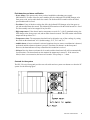
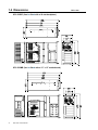
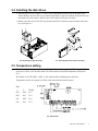
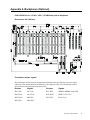
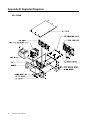
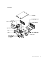
SPC-530
Rackmount Server PC
User's Manual
Copyright Notice
This document is copyrighted, April 2000, by Advantech Co., Ltd. All rights are reserved. Advantech
Co., Ltd. reserves the right to make improvements to the products described in this manual at any time
without notice.
No part of this manual may be reproduced, copied, translated or transmitted in any form or by any
means without the prior written permission of Advantech Co., Ltd. Information provided in this manual
is intended to be accurate and reliable. However, Advantech Co., Ltd. assumes no responsibility for its
use, nor for any infringements of the rights of third parties which may result from its use.
Acknowledgments
SPC-530MB, SPC-530BP, SPC-530MB-U2C, SPC-530BP-U2C series and PCA-6120P4,
PCA-6119P7, PCA-6119P17, PCA-6120DP4, PCA-6118DP7 series are trademarks of Advantech Co.,
Ltd.
NOTE:
The information in this document is provided for reference only. Advantech does not assume any liability arising
out of the application or use of the information or products described herein. This manual is subject to change
without notice.
Part No. 2002053000
Printed in Taiwan
1st Edition
April 2000
Contents
Chapter 1 General Information ................................................................... 1
1.1 Introduction ................................................................................................................. 1
1.2 Model list ................................................................................................................... 1
1.3 Specifications ............................................................................................................ 1
1.4 Dimensions ................................................................................................................ 4
Chapter 2 System Setup ............................................................................. 5
2.1 Removing the cover.................................................................................................... 5
2.2 Removing the handles ................................................................................................ 6
2.3 The cooling fans ......................................................................................................... 6
2.5 Temperature setting .................................................................................................... 7
2.4 Installing the disk drives .............................................................................................. 7
2.6 Installing the power supply unit .................................................................................... 8
Appendix A Backplanes (Optional) ................................................................................... 9
Appendix B Exploded Diagrams .................................................................................... 12
Appendix C Safety Instructions ....................................................................................... 14
Chapter 1 General Information
1.1 Introduction
The SPC-530MB / SPC-530BP, the PC/AT-compatible computer, is designed for high-reliability applications. Not only easily installed and maintained in mission critical applications and harsh environments, it
is also a high-end rackmount fault-resilient server PC. The SPC-530BP can be fitted with a 20-slot
PC-bus compatible passive backplane. The SPC-530MB can be fitted with an ATX motherboard. Both
the SPC-530BP and SPC-530MB provide one 400-watt ATX redundant power supply and three
hot-swap cooling fans. They accept up to six front-access half-height disk drives.
The SPC-530BP / SPC-530MB features an advanced fault detection and alarm notification system to
monitor its own hardware status. If your PC system shuts down without advance warning, this can be
dangerous and may cause considerable loss.
1.2 Model list
SCSI Ultra2 Wide
RAID Card w / cable
Disk Cartridges
x 5 sets
YES
----
----
*** (Reserve the space for
ATX mother board )
YES
----
----
SPC-530BP-U2C
20-slot passive backplane
YES
YES
YES
SPC-530MB-U2C
*** (Reserve the space for
ATX mother board )
YES
YES
YES
Model Name
Backplane
SPC-530BP
20-slot passive backplane
SPC-530MB
Redundant, Hot-sw ap
400-w att ATX AC-DC PSU
The SPC-530BP-U2C and SPC-530MB-U2C include five disk cartridges installed in vertical disk drive
space. There is one horizontal disk drive space reserved for other storage drives such as a CD-ROM
drive.
1.3 Specifications
• Construction: Heavy-duty steel chassis
• Disk drive capacity: Five half-height front-access drives (vertical), and one half-height drive (horizontal)
• Cooling system: Three 86 CFM cooling fans inside the chassis
• Controls: Power On/Off switch on power supply module in front panel. Alarm reset button, ATX soft
switch and system reset button on the front panel
• Indicators: Bicolor LEDs (green and red) for power failure, fan failure and overheating. LED
indicator (green) for system power On/Off
• Buzzer: One buzzer for audio alarm / volume control on board
• Dimensions: 19" (W) x 8.75" (H) x 26" (D), 482 mm (W) x 222 mm (H) x 660 mm (D)
• Net weight: SPC-530MB / SPC-530BP: 46.2 lb (21 kg)
SPC-530 User's Manual
1
• Paint color: Front panel: Pantone Black 4C 2X; Chassis: Brushed finish, Ni
• Operating temperature: 0 to 50o C (32 to 122o F)
• Relative humidity: 20 to 90%
• CE compliant
Hot-swap AC-DC 400-watt ATX redundant power supply (RPS-400ATX)
• Output rating: 400 watts (max.)
• Input voltage: 90 to 132 VAC or 180 to 264 VAC @ 47 ~ 63 Hz, switchable
• Output voltages: +5 V @ 42 A, +3.3 V @ 20 A, +12 V @ 14 A, -5 V @ 1 A, -12 V @ 1 A
+5 Vsb @ 0.75 A (+5 V / +3.3 V; Total: 210 watts)
• Minimum load: +5 V @ 2 A, +3.3 V @ 0.3 A, +12 V @ 0.5 A
• MTBF: 100,000 hours at 25o C, 70% load
• Safety: UL/C-UL/TUV/CE approved
Passive backplane options (for SPC-530BP / SPC-530BP-U2C)
Backplane Model Name
Slots per Segment
Segment(s)
PCA-6120P4
15 ISA / 4 PCI / 1 PICMG
Single
PCA-6119P7
11 ISA / 7 PCI / 1 PICMG
Single
PCA-6119P17
1 ISA / 17 PCI / 1 PICMG
Single
RAID card features (only for SPC-530BP-U2C / SPC-530MB-U2C)
The SPC-530 is available with a RAID to PCI host interface. This gives users numerous extra features.
(For more details, please refer to our RAID manual, under SPC-530BP-U2C / SPC-530MB-U2C)
• One/Two Ultra2 Wide SCSI (68-pin) channel(s) on-board
• Automatic bad sector reassignment, Bad Sector Management
• Built-in SCSI terminator
• RAID 0, 1 (0+1), 3, 5
• Auto-rebuilding
• Hot-spare drive operation
• Disk hot-swapping
• Self-diagnostics
• Complete OS support: MS-DOS, Windows 95/98, Windows NT, NetWare, OS/2, SCO UnixWare,
Sun Solaris and Linux
2
SPC-530 User's Manual
Fault detection and alarm notification
• Power failure: This operates only when you have installed the redundant power supply
(RPS-400ATX). If either of the two power modules fails, the dedicated LED (PWR) changes color
from green to red, and an audio alarm also sounds. The dedicated LED remains red for the failed
power module until it is fixed.
• Fan failure: If any of the three cooling fans fails, the dedicated LED changes color from green to
red, and an audio alarm also sounds. The dedicated LED remains red for the failed fan until it is fixed.
The fan assembly can be hot-swapped if any fan fails.
• High temperature: If the chassis interior temperature exceeds 65o C (149o F) (standard setting), the
LED changes color from green to red, and an audio alarm also sounds. The LED remains red until the
temperature drops below 63o C.
• Temperature select: The temperature threshold can be adjusted to one of four readings, by setting
the switch on the alarm board: 65o C (default setting), 55o C, 70o C and 75o C.
• Audible alarm: A buzzer on board is activated (continous beep) as soon as a malfunction is detected,
and sounds until the alarm reset button is pressed. The alarm reset button is on the front panel.
However, the alarm indicator will stay red until the fault condition is resolved.
• Self-test: Press the alarm reset button for 8 seconds, and the alarm board will self-test automatically
for all functions. The alarm board can also monitor the temperature's sensor IC. If the sensor has
failed, or there is no connection, the buzzer will sound a " Beep x Beep x ..." alarm.
Controls for the system
The SPC-530 series' front panel provides one soft switch and one system reset button to re-boot the PC
system. See the following figure:
SPC-530 User's Manual
3
1.4 Dimensions
SPC-530BP (Can be fitted with a 20-slot backplane)
SPC-530MB (Can be fitted with a 12" x 13" motherboard)
4
SPC-530 User's Manual
Unit = mm
Chapter 2 System Setup
The SPC-530 series is an ATX-compatible computer designed for industrial applications. This rugged
chassis meets the EIA RS-310C 19" rackmount standard.
Setting up your SPC-530 series requires only a screwdriver and a small amount of time. Before you
begin, you should also gather together all of the cards you plan to install, as well as the disk drives you
plan to use.
WARNING:
Disconnect all power from the chassis before you install
the CPU cards. Unplug the power cord from the wall,
Do not just turn off the power switch. If you are not sure
what to do, take the job to an experienced professional.
2.1 Removing the cover
There are screws near the top, along the sides, and on the rear to secure the cover to the chassis.
Remove them, and then you can lift the cover free of the chassis. See Figure 2.1 below:
2.1 Removing the cover
SPC-530 User's Manual
5
2.2 Removing the handles
The handles and mounting ears for the front panel can be removed as follows. Please see Figure 2.2
below:
2.2 Removing the handles
2.3 The cooling fans
There are three cooling fans inside the chassis. To replace or service the fans, open the top cover as in
Figure 2.1. Loosen the thumbscrews, and pull out the whole fan assembly. Please refer to Figure 2.3
below:
2.3 Cooling fans
6
SPC-530 User's Manual
2.4 Installing the disk drives
1. Open the top cover as in Figure 2.1. There is one independent disk drive bay on the front of the
chassis. Remove the four outer screws which mount the drive bay to the chassis. Slide the drive bay
toward the rear of the chassis, and lift it free of the chassis. See Figure 2.4 below.
2. Remove the front cover of the drive bay, and insert the drives into their proper locations in the drive
bay. See Figure 2.5.
2.4 Removing the disk drive bay
2.5 Inserting the drives into the drive bay
2.5 Temperature setting
If the chassis interior temperature exceeds 65o C (149o F) (default setting), the LED changes color from
green to red. There is also an audio alarm. The LED remains red until the temperature drops below
63o C.
The default of the "RF_JMP" is PIN1-2: ON, which enables redundant power detection.
Temperature can also be selected (via SW1) on the alarm board inside the chassis:
SW1
1
2
TEMP
OFF
OFF
65o C
OFF
ON
55o C
ON
OFF
70o C
ON
ON
75o C
2.6 Alarm board
SPC-530 User's Manual
7
2.6 Installing the power supply unit
There is one 400 W ATX redundant power supply installed at the front of the chassis. The power
module can be hot-swapped for maintainence.
2.7 ATX redundant power supply
8
SPC-530 User's Manual
Appendix A Backplanes (Optional)
PCA-6120P4 Rev. A1: 15 ISA / 4 PCI / 1 PICMG-slot passive backplane
Dimensions: 420 x 260 mm
Termination resistor signals
The termination resistors provide an impedance mismatch at the end of the bus, to prevent signal
reflections. This mismatch has to be balanced by the capability of the CPU and optional cards to
electrically drive the load imposed by the resistor.
Resistor
Signals
Resistor
Signals
RN1, RN8
SA7-SA0
RP1, RP2
MEMW, SMEMR, IOW, IOR
RN4, RN11
SA15-SA8
RN2, RN12
SBHE, LA23-LA17
RN5, RN10
SD0-SD7
RN6, RN7
SA19-SA16
RN3, RN9
SD8-SD15
SPC-530 User's Manual
9
PCA-6119P7 Rev. A1: 15 ISA / 4 PCI / 1 PICMG-slot passive backplane
Dimensions: 420 x 260 mm
10
SPC-530 User's Manual
PCA-6119P17 Rev. A1: 1 ISA / 17 PCI / 1 PICMG-slot passive backplane
Dimensions: 420 x 260 mm
SPC-530 User's Manual
11
Appendix B Exploded Diagrams
SPC-530MB
12
SPC-530 User's Manual
SPC-530BP
SPC-530 User's Manual
13
Appendix C Safety Instructions
1.
Please read these safety instructions carefully.
2.
Please keep this User's Manual for later reference.
3.
Please disconnect this equipment from any AC outlet before cleaning. Do not use liquid or
sprayed detergent for cleaning. Use a moist sheet or cloth.
4.
For pluggable equipment, the socket-outlet must be installed near the equipment and must be
easily accessible.
5.
Please keep this equipment free from humidity.
6.
Lay this equipment on a reliable surface when installed. A drop or fall could cause damage.
7.
The openings on the enclosure are for air convection, so protect the equipment from overheating.
DO NOT COVER THE OPENINGS.
8.
Make sure of the voltage of the power source when connecting the equipment to the power
outlet.
9.
Position the power cord such that people cannot step on it. Do not place anything over the power
cord.
10.
All cautions and warnings on the equipment must be noted.
11.
If the equipment is not used for a long time, disconnect it from the mains. This prevents the
equipment from being damaged by transient overvoltage.
12.
Never pour any liquid into an opening. This can cause fire or electrical shock.
13.
Never open the equipment. For safety reasons, the equipment should only be opened by qualified
service personnel.
14.
If one of the following situations arises, get the equipment checked by service personnel:
a. The power cord or plug is damaged.
b. Liquid has penetrated into the equipment.
c. The equipment has been exposed to moisture.
d. The equipment does not work well or you cannot get it to work according to the user's
manual.
e. The equipment has been dropped or damaged.
f. The equipment has obvious signs of breakage.
15.
DO NOT LEAVE THIS EQUIPMENT IN AN UNCONDITIONED ENVIRONMENT WITH
STORAGE TEMPERATURES BELOW -20oC (-4oF) OR ABOVE 60oC (140oF), AS THIS
MAY DAMAGE THE EQUIPMENT.
The sound pressure level at the operator's position according to IEC 704-1:1982 is equal to or less than
70 dB(A).
14
SPC-530 User's Manual