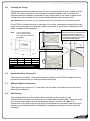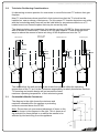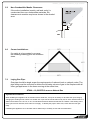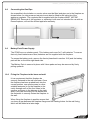
1
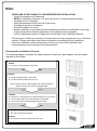
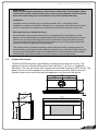
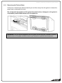
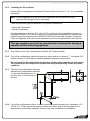
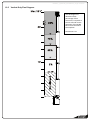
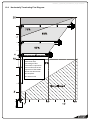
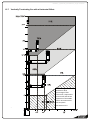
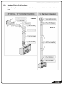
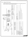
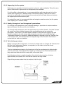
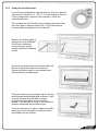
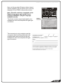
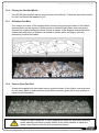
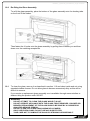
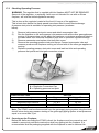
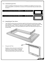
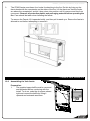
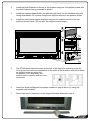
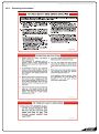
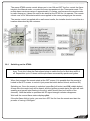
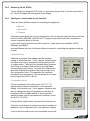
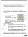
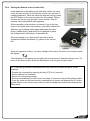
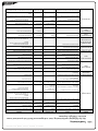
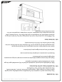
630167_5_Manual_Installation_US_R-emotion ST900 Direct Vent Gas Fireplace Installation Manual NORTH AMERICA EDITION WARNING: If the information in these instructions are not followed exactly, a fire or explosion may result causing property damage, personal injury or loss of life. - Do not store or use gasoline or other flammable vapors and liquids in the vicinity of this or any other appliance. - WHAT TO DO IF YOU SMELL GAS Do not try to light any appliance. Do not touch any electrical switch do not use any phone in your building. Immediately call your gas supplier from a neighbors phone. Follow the gas suppliers instructions. If you cannot reach your gas supplier, call the fire department. - Installation and service must be performed by a qualified installer, service agency, or the gas supplier. INSTALLER: Leave this manual with the appliance. CONSUMER: Retain this manual for future reference. Ce manual est disponsible en Français sur demande. www.escea.com This appliance may be installed as an OEM installation in a manufactured home (USA only) or mobile home and must be installed in accordance with the manufacturer’s instructions and the Manufactured Home Construction and Safety Standard, Title 24 CFR, Part 3280, in the United States, or the Standard for Installation in Mobile Homes, CAN/CSA Z240 MH, in Canada. This appliance is only for use with the types of gas indicated on the rating plate. A conversion kit is supplied with the appliance. This appliance may be installed in an aftermarket, permanently located, manufactured home (USA only) or mobile home, where not prohibited by local codes. This appliance is only for use with the types of gas indicated on the rating plate. A conversion kit is supplied with the appliance. Manufactured By: Escea International Limited, 375b Green Valley Road, Griffen, GA 30224 USA. Ph: 866 615 3096 | [email protected] 630167_5_Manual_Installation_US_R-emotion Important: The appliance shall be installed in accordance with; • This installation instruction booklet • Local codes or, in the absence of local codes, with the National Fuel Gas Code, ANSI Z223.1/NFPA 54, or the Natural Gas and Propane Installation Code, CSA B149.1 • A manufactured home (USA only) or mobile home OEM installation must conform with the Manufactured Home Construction and Safety Standard, Title 24 CFR, Part 3280, or, when such a standard is not applicable, the Standard for Manufactured Home Installations ANSI/NCSBCS A225.1, or Standard for Gas Equipped Recreational Vehicles and Mobile Housing, CSA Z240.4 • Any other relevant statutory regulations. • Must be installed by a qualified installer, service agency or gas supplier • Converting this appliance for use with other gasses must be done by a qualified installer, service agency, or gas supplier Warning: - - - Due to high temperatures, the ST900 should be located out of traffic and away from furniture and draperies. The area around the ST900 MUST be kept clear and free from combustible materials, gasoline and other flammable vapors and liquids. Children and adults should be alerted to the hazards of high surface temperature and should stay away to avoid burns or clothing ignition. Clothing or other flammable material should not be placed on or near the ST900. Any safety screen or guard removed for servicing the ST900 must be replaced prior to operating it. Installation and repair should be done by a qualified service person. The ST900 should be inspected before use and at least annually by a professional service person. More frequent cleaning may be required due to excessive lint from carpeting, bedding material, et cetera. It is imperative that control compartments, burners and circulating air passageways of the ST900 be kept clean. Do not use this appliance if any part has been under water. Immediately call a qualified service technician to inspect the appliance and to replace any part of the control system and any gas control which has been under water. Caution: Label all wires prior to disconnection when servicing controls. Wiring errors can cause improper and dangerous operation. Verify proper operation after servicing. Young children should be carefully supervised when they are in the same room as the appliance. Toddlers, young children and others may be susceptible to accidental contact burns. A physical barrier is recommended if there are at risk individuals in the house. To restrict access to a fireplace or stove, install an adjustable safety gate to keep toddlers, young children and other at risk individuals out of the room and away from hot surfaces. 630167_5_Manual_Installation_US_R-emotion Note: THERE ARE A FEW THINGS TO CONSIDER BEFORE INSTALLATION • Cavity Dimensions and Clearances • MUST be installed a minimum of 4” above the floor or nearest horizontal surface. • Coupling of flue to fireplace • Gas pipe placement to the front left of the cavity. • Coupling of gas lines to fireplace • Fixing the fireplace to cavity • Before installation, ensure that the local distribution conditions (identification of the type of gas and pressure) and the adjustment of the appliance are compatible. • A list of replacement parts is in Appendix D at the end of this Installation Manual The sequence in which you choose to do these tasks will vary depending on your individual scenario. Please read these instructions fully before proceeding with the installation. Leave the installation of the fascia panels until the very end of the installation and commissioning to avoid damage to the fascia panels. Recommended Installation Process: The following diagram illustrates the steps required to install your gas fireplace, and the trades required at each stage. Builder 1. Construct Frame (Section 1.0 to 6.0) Gasfitter 2. Install Gas Pipe (Section 7.0 to 8.0) 3. Install Fireplace (Section 9.0 to 11.0) Ensure that you leave a gap between the studwork and fire chassis to accept the wall lining if applicable. Gasfitter 4. Install Flue + Flue Restrictor if required (Section 12.0 to 13.0) 5. Test fireplace and verify flame pattern is acceptable 6. Cover-up fireplace using packaging (Section 18.0) Builder 7. Dry wall / clad chimney breast Gasfitter 8. Commission the Gas Fireplace (Section 19.0) 630167_5_Manual_Installation_US_R-emotion Contents: 1.0 2.0 3.0 4.0 5.0 6.0 7.0 8.0 9.0 10.0 11.0 12.0 13.0 14.0 15.0 16.0 17.0 18.0 19.0 20.0 21.0 22.0 23.0 24.0 25.0 Product Description Creating the Cavity Hearth and Floor Clearances Wall Linings Vertical Clearances Corner Installations Laying Gas Pipe Connecting Gas Pipe Power Supply Fixing Fireplace to Wall Removing the Firebox Glass Installing the Flue system Fitting the Flue restrictor Converting to Propane Gas Placing the Fuel Bed Re-fitting the Glass Assembly Checking Operating Pressure Covering up the Fireplace Commissioning the Fireplace (Including fitting the fascia) Operating Instructions Sounds and Smells Annual Service Check Installation Check List Appendix Warranty Terms and Conditions 630167_5_Manual_Installation_US_R-emotion WARNING: Failure to follow these instructions could cause a malfunction of the fireplace, which, could result in death, serious bodily injury, and/or property damage. Failure to follow these instructions may also void insurance cover and/or product warranty. Installation: Installation must be carried out by a registered installer who, on completion of the installation, must issue a certificate of compliance, in accordance with national and/or local codes. If a certificate of compliance is not issued then the Escea warranty may be void. Warranty Repair and Annual Servicing: Warranty repair work must be carried out by a recognised Escea gas fireplace service agency. It is recommended that recognised Escea Gas fireplace service agencies are also used to carry out annual servicing requirements (particularly during the warranty period). For contact details of authorised Escea service agencies in your area, please contact the retailer from whom the appliance was purchased. This product must be installed according to these instructions and in compliance with all relevant building, gas fitting and other statutory regulations (eg. ANSI Z223.1/NFPA 54). Any shortcomings in the appliance and flue installation will be the responsibility of the installer, and Escea will not be accountable for any such failings or their consequences. 1.0 Product Description: The Escea ST900 decorative gas fireplace is designed to be built into a cavity. The appliance is flued via Simpson Duravent Direct Vent Pro 5” x 8” Flue, or compatible equivalent. The user will control their fireplace with the Radio Frequency (RF) remote. The glass on the front of the appliance is considered a working surface, and as such care should be taken not to touch this while the appliance is running as it will get hot. 35 12” 17 13 16 ” 1713 16 ” 1315 16 ” 13 34” 2 44 16 ” 2213 16 ” 21 12” 15 7 5 16 ” 7 16 ” 630167_5_Manual_Installation_US_R-emotion 2.0 Creating the Cavity: The dimensioned drawing below shows the size of opening that must be created to fit the ST900. The wall directly above the fireplace should be finished / clad / lined after the fireplace has been installed, unless there is an access hatch or the chase is open to the ceiling cavity, which allows the flue to be installed after the wall has been lined. See Appendix C at the back of this installation manual for clearances to combustible materials. If the ST900 is installed directly on carpeting, tile or other combustible material other than wood flooring, the appliance shall be installed on a metal or wood panel extending the full width and depth of the appliance. Note: It is not necessary to line or vent the cavity, and it may be constructed with timber. Velo Fascia The wall and framework in front of the flue must not exceed 4” in thickness, this includes dry wall or any other wall linings. This is to ensure there is at least 1” gap between all flueing components and any combustible material. Ferro Fascia H W D Velo 22 1/2” 37” 15 1/2“ Ferro 21 7/8” 35 7/8” 15” For Velo fascias, the fire must be recessed 1/2” into the cavity If unsure which fascia type, see diagram in section 19.0 3.0 Hearth and Floor Clearances: There must be at least 4” clearance between the bottom of the ST900 fireplace and any horizontal surface below, for example hearths and floors. 3.1 Wall and Cabinet Clearances: There must be a minimum of 4” clearance from the sides of the fascia to any protruding side walls or cabinetry. 4.0 Wall Linings: The wall board that lines the outside of this opening can be normal dry wall (Plaster Board) and does not need to be non-combustible providing that it does not come any closer to the fireplace than the dimensions shown in section 2.0. Note: The temperature of the wall lining directly above the fireplace does get warm and hence may discolour paint finishes that are susceptible to temperature damage or distort vinyl wall coverings. 630167_5_Manual_Installation_US_R-emotion 5.0 Television Positioning Considerations: It is becoming common practice for consumers to mount flat screen TV‟s above their gas fireplace. Most TV manufacturers have specified in their instructions that the TV should not be installed on, near or above a heat source. For this reason TV location decisions rest solely with the householder and Escea will not be held liable for any adverse affects on a TV located near to an Escea fireplace that may be caused by heat. The drawings below are suggestions that may be used as a GUIDE for those consumers who do decide to locate their TV above an ST900 gas fireplace. These drawings show ways to reduce the amount of warm air rising off the fireplace and onto the TV. Flush TV with small mantle Recessed TV Mantle above fire Protruding fire 2” 2” 2” 2” 4” 2” 2” 2” 4” Mantle Mantle 20” 20” 20” 20” The material that the wall and mantle are made from will also affect the operating temperature of the TV so it is the customers responsibility to satisfy themselves that their TV mounting and mantle design will not exceed the listed maximum operating temperature of their electronic goods. 5.1 Combustible Mantle Clearances: The diagram to the right shows the minimum and maximum allowable size for mantles or protruding surfaces mounted above the ST900. Note: Escea does not recommend placement of items on the mantles shown in the diagram to the right. This is because of the potential for items placed on or above the mantle to be affected by the heat rising from the appliance. 630167_5_Manual_Installation_US_R-emotion 5.2 Non-Combustible Mantle Clearances: If the entire installation (mantle, wall and cavity) is constructed from non-combustible materials, the clearances to mantles may be as shown in the shaded area. 6.0 Corner Installations: If a cavity is to be created in a corner, the following drawing gives the minimum sizes. 7.0 Laying Gas Pipe: Gas pipe should be sized as per the requirements of relevant local or national codes. The pipe sizing must be sufficient to deliver the following volume of gas to the fireplace with all other gas appliances in the home running at the same time; ST900 = 19,500 BTU/h max on Natural Gas High Altitude Installations When installing this appliance at an elevation above 2000 feet, it may be necessary to decrease the input rating by changing the existing burner orifice to a smaller size. Input rate should be reduced by 4% for each 1000 feet above a 2000 foot elevation in the U.S.A, or 10% for elevations between 2000 and 4500 feet in Canada. If the heating value of the gas has ben reduced, these rules do not apply. To identify the proper orifice size, check with the local gas utility. If installing this appliance at an elevation above 4500 feet (in Canada), check with local authorities. 630167_5_Manual_Installation_US_R-emotion 8.0 Connecting the Gas Pipe: An accessible inline isolation or service valve must be fitted and pipe run to the fireplace as shown below. An inlet pressure test point must also be fitted to the inlet side of the appliance regulator. The regulator that is supplied with the fireplace MUST NOT BE REMOVED. Removal of the regulator, or replacing it with one not intended for use with an Escea fireplace, will void the limited appliance warranty. 9.0 Battery-Pack Power Supply: The ST900 runs on a battery pack. This battery pack uses 3x C cell batteries. To ensure that only fresh batteries are used, batteries are not supplied with the fireplace. To access the battery pack, remove the fascia (described in section 19.2) and the battery pack will be on the lower right hand side. The Battery Pack is secured in place with Velcro pads and may be removed by firmly pulling upwards. 10.0 Fixing the Fireplace to the base and wall: It is a requirement that this fireplace be securely fastened to the wall and base. Once the fireplace has been pushed back into the correct position, use wood screws (or other suitable fasteners) to fix the fireplace to the cavity through each of the four holes in the corners, as shown in the diagram to the right. Note: It may be necessary to use washers on the fasteners to securely fasten the fireplace to the wall. When fixing the fireplace in position ensure that you leave a gap between the fireplace flange and the framing timber for the wall lining, which will be added at a later stage. 630167_5_Manual_Installation_US_R-emotion 11.0 Removing the Firebox Glass: Pull the four hooks shown below towards you and then away from the glass to release the glass frame underneath the hook. Do not operate the appliance if the glass has been broken, damaged, or the glass is not properly positioned/hooked onto the appliance. WARNING: Do not operate appliance with the glass format removed, cracked or broken. Replacement of the glass should be done by a licensed or qualified service person. 630167_5_Manual_Installation_US_R-emotion 12.0 Installing the Flue System: Ensure all flue components are Simpson Duravent Direct Vent Pro 5” x 8,” or a compatible equivalent. Note: Consult Appendix A at the end of this installation manual (section 24.0) to ensure correct length of flue is calculated. There are two basic types of Balanced Flue System installations: • Horizontal Termination • Vertical Termination Use the diagrams in sections 12.5, 12.6 & 12.7 to check if your proposed flue system is acceptable. Section 12.9 will also need to be used to determine whether the flue terminal location meets the requirements of ANSI Z21.88-2009 Vented Gas Fireplace Fireplaces. Then use Appendix A to work out the quantities of the flue components that are required. This gas appliance must not be connected to a chimney flue serving a separate solid-fuel burning appliance 12.1 Any offsets in your flue configuration should be 45° where possible. 12.2 If your flue configuration has a horizontal run, there must be a minimum 1 ° inclination (3/4” vertical rise per 3‟ horizontal run) leading upwards towards the termination. Do not install the flue with horizontal sections sloping down towards the termination. This could cause the fireplace to operate incorrectly and possibly create an unsafe condition. 12.3 The flue must maintain the following clearances to combustible materials; 1” from all sides and bottom of the flue, and 2” from the top of the flue. 12.4 If your flue configuration falls on or near a restriction zone boundary line in diagrams 12.5, 12.6 & 12.7, it may require the restriction value from either side of the boundary line to achieve the correct flame aesthetic, this may vary from installation to installation. 630167_5_Manual_Installation_US_R-emotion 12.5 Vertical Only Flue Diagram: Use this diagram to determine what percentage of flue restriction is required to ensure safe and correct operation of the ST900 Direct Vent Decorative Gas Fireplace. See Section 13.0 630167_5_Manual_Installation_US_R-emotion 12.6 Horizontally Terminating Flue Diagram: Use this diagram to determine what percentage of flue restriction is required to ensure safe and correct operation of the ST900 Direct Vent Decorative Gas Fireplace. See Section 13.0 630167_5_Manual_Installation_US_R-emotion 12.7 Vertically Terminating flue with a Horizontal Offset: Use this diagram to determine what percentage of flue restriction is required to ensure safe and correct operation of the ST900 Direct Vent Decorative Gas Fireplace. See Section 13.0 .. 630167_5_Manual_Installation_US_R-emotion 12.8 Standard Flueing Configurations: The following flue components are available from your escea distributor/retailer in kitset form. DVF-H DVF-V 630167_5_Manual_Installation_US_R-emotion 12.9 Locating the Flue Terminal: The flue terminal must be located using the information given in the following excerpt from ANSI Z21.88-2005 Vented Gas Fireplace Fireplaces. 630167_5_Manual_Installation_US_R-emotion 12.10 Supporting the flue system: Wall straps are required to fix the flue system in place for each installation. This will ensure that no undue strain is placed on flue components once installed. For a flue offset or horizontal run, it is recommended that wall straps be used to the flue system with a spacing of 3‟ between straps. Plumbers strapping / tape can be used to connect the wall straps to the building structure where there are large distances between the support point and the anchor point. For vertical flue runs it is recommended that wall straps be used to anchor the flue system with a spacing of 4‟ between straps. 12.11 Sealing ‘through roof’ and ‘through wall’ penetrations: For „through roof‟ penetrations, use a Decktite flashing or equivalent to create a weathertight seal between the flue and the roof cladding. For „through wall‟ penetrations, this will require the use of a Wall Thimble. The Wall Thimble will ensure you have suitable clearance from combustibles as well as sealing the penetration. The section of the wall thimble installed on the external surface of the wall should be sealed to the wall using a high temperature sealant such as Mill-Pac High Temperature Sealant or equivalent. Additional sealant is required to seal the Terminal Cap to the external wall. A bead should be run along the edge of the Terminal that will be in contact with the wall once installed. 12.12 Twist locking procedure: Before connecting flue components, to ensure an airtight seal run a single 1/8” wide bead of Mill-Pac High Temperature Sealant, or equivalent, on the „male‟ end of the flue as shown in the diagram below. The four indentations located on the female end of the flue are designed to slide straight onto the male ends of the adjacent flue length, by orienting the four flue indentations so they match and slide into the four entry slots on the male ends. Push the pipe sections completely together, then twist-lock one section clockwise approximately one-quarter turn, until the two sections are fully locked. Wipe off any excess sealant from the exterior of the flue joint. 630167_5_Manual_Installation_US_R-emotion 13.0 Fitting the Flue Restrictor: If your flueing configuration requires that you fit a flue restrictor (see graph in section 12.5, 12.6, 12.7 of this manual to find out if your configuration requires a flue restrictor), follow the instructions below. First, prepare the Flue Restrictor by removing and discarding the inner rings to achieve either 60% or 70% restriction as required and hand bending the five tabs 90° Remove the firebox glass (if fitted), and using a Phillips / Pozi Drive screwdriver remove the two screws located inside the firebox as shown. Once the two screws are removed the baffle will be free to slide down and out as pictured. Ensure the firebox paint is not scratched and that the baffle is not damaged Fit the flue restrictor by pushing it up into the flue with the tabs facing downwards as shown. Push it up into the flue until the tabs no longer protrude into the firebox and it is securely placed. If the restrictor is loose or will not stay in position manipulate the five tabs to suit. Once the restrictor is in place, replace the baffle taking care not to damage or scrape the paint, and replace the two screws. 630167_5_Manual_Installation_US_R-emotion 14.0 Converting to Propane Gas: Where a conversion to propane gas is needed, the following steps should be followed 14.1 First you need to remove the burner by removing the screw holding it in place on the left hand side of the firebox (Fig. 1). Then remove the 1.9mm burner jet (Fig. 2) and replace it with the 1.2mm jet supplied in the kit. Now remove the gas pipe fitting under the pilot (Fig. 3) and remove the No.48 pilot Jet (Fig. 4) and replace it with the No.46 pilot jet supplied in the kit. Replace pilot line. Adjust the Primary Aeration Collar on the burner to the Propane position as shown in the diagram below, then place the burner into position and screw it in place. The gas regulator needs to be converted from the Natural Gas setting to the Propane setting. The regulator is located on the left hand side of the control tray, at the base of the fireplace. To change the regulator between Natural Gas and Propane, unscrew the top cap off the regulator and pull the plunger from it. Re-insert the plunger on the opposite side (as shown in the diagram to the right) and screw the assembly back in the stack 630167_5_Manual_Installation_US_R-emotion Now, put the gas data (Propane sticker shown) sticker supplied in the conversion kit in onto the dataplate of the ST900 in the position shown. ST900 Note: This will need to be completed on the English language as well as the French language dataplates. (English language dataplate shown) The sticker must be signed and dated by the tradesperson who has completed the gas type conversion. Sticker R C The conversion is only complete once the conversion label has been adhered to the available label plate and filled out by the tradesperson who has completed the gas type conversion. US US Edition 630167_5_Manual_Installation_US_R-emotion 15.0 Placing the Fuel Bed Media: Your ST900 Gas fireplace will be supplied with a Fuel Bed kit. Follow the instructions below for the Fuel Bed kit that applies to you. 15.1 Driftwood Fuel Bed: First scatter one layer of the supplied white stones evenly across the base of the firebox, ensuring there are no stones or driftwood pieces inside the pilot flame surround guard. Arrange the supplied driftwood pieces exactly as shown in the diagram and photo below. Underneath each piece of driftwood a number is written which will help in correctly positioning it within the firebox. 15.2 Coal or Glass Fuel Bed: Scatter the supplied fuel bed media evenly across the base of the firebox, ensuring there are no coals, glass or media inside the pilot flame surround guard which may obstruct or impair the pilot assembly. Ensure no coals, driftwood, or other material are inside the pilot flame surround guard, and the pilot flame is clearly visible. If any loose material is inside this guard it may interfere with the pilot and ignition system. 630167_5_Manual_Installation_US_R-emotion 16.0 Re-fitting the Glass Assembly To re-fit the glass assembly, place the bottom of the glass assembly onto the locating tabs on the front of the firebox. Then fasten the 4 hooks onto the glass assembly by pulling them towards you and then down over the matching receptacles. 16.1 To clean the glass, remove it as described in section 11.0 and clean inside and out using standard window cleaner. Do not allow glass to become excessively dirty as this will be difficult to remove. If you require a replacement glass assembly one is available through escea retailers or dealers using the product code: 802207 WARNING: - - DO NOT ATTEMPT TO CLEAN THE GLASS WHILE IT IS HOT. DO NOT OPERATE APPLIANCE WITH THE GLASS FRONT REMOVED, CRACKED OR BROKEN. REPLACEMENT OF THE GLASS SHOULD BE DONE BY A LICENSED OR QUALIFIED SERVICE PERSON. DO NOT CLEAN THE GLASS USING ABRASIVE CLEANERS. ONLY USE ESCEA GLASS, DO NOT USE ANY SUBSTITUTES. TAKE CARE NOT TO DAMAGE THE GLASS BY STRIKING OR DROPPING IT. 630167_5_Manual_Installation_US_R-emotion 17.0 Checking Operating Pressure: WARNING: The regulator that is supplied with the fireplace MUST NOT BE REMOVED. Removal of the regulator, or replacing it with one not intended for use with an Escea fireplace, will void the limited appliance warranty. This is done at the regulator located at the front LH corner of the appliance. This is best done before the fascia panels have been fitted to avoid fascia damage. A pressure test point is available for operating test pressure (as shown below). 1) 2) 3) 4) 5) Remove inlet pressure test point screw and attach manometer tube. Run the fireplace on full and measure inlet pressure with all the other gas appliances running. If pressure does not fall within the maximum or minimum pressures listed on the table below then reassess installation pipe size or upstream regulator settings. Remove manometer and replace inlet test point screw. Remove the operating pressure test point screw. Connect manometer tube and measure pressure with fireplace running on full and with all the other gas appliances running. Replace operating pressure test point screw and leak test inlet and operating pressure test points and inlet gas connection unions. A = Regulator Conversion Cap B = Operating pressure test point ST900 Pressure Table Minimum Inlet Pressure Maximum Inlet Pressure Operating Pressure Gas Type Propane 11” w.c. 13” w.c. 9.4” w.c. Natural Gas 5.5” w.c. 10” w.c. 4” w.c. Note: The ST900 must be disconnected from the gas supply piping system using the inline shutoff valve during any pressure testing of the gas supply piping system at test pressures equal to or more than ½ psi. 18.0 Covering up the Fireplace: Before the wall surrounding the ST900 is lined, the fireplace must be covered up and sealed to prevent dry wall and construction dust from getting into the fireplace. It is recommended that the packaging supplied with the fireplace is used to achieve this. 630167_5_Manual_Installation_US_R-emotion 19.0 Commissioning the Fire: After the cladding and finishing processes are completed, the gasfitter must return to the site to fit the grill trim, run the fire for a minimum of 20 minutes and finally assemble and fit the fascia. → If you are installing the ST900 with a FERRO fascia: SEE SECTION 19.1 → If you are installing the ST900 with a VELO fascia: SEE SECTION 19.2 19.1 Assembling the Ferro fascia: 1. The ST900 Ferro fascia has two brackets supplied in the fascia box which have not been fully assembled. To assemble them use the 4x screws supplied to fasten the brackets to the fascia as shown below. Position the brackets with the flange facing outwards, and the hooks facing the bottom of the fascia [Identify the bottom of the fascia by the large cut-out shown below]. 2. Fitting the Grill Trim: Packed in with the fascia kit is the Grill Trim. Attach this to the fire using the 3 supplied screws in the positions shown to the right. The perforated surface (grill) should be on top. 630167_5_Manual_Installation_US_R-emotion 3. The ST900 fascia uses these four hooks for attaching to the fire. Do this by lining up the fascia hooks with the receptacles on the sides of the fire. Lift the fascia so that the hooks are above the receptacles, and let it drop down into position until it is secure and free from movement. Remove all protective plastic and packaging material before operating the fire. Care should be taken when handling the fascia. To remove the Fascia, lift it upwards briefly, and then pull towards you. Ensure the fascia is allowed to cool before attempting to remove it. → Continue on to section 20.0 19.2 Assembling the Velo fascia: Preparation: 1. The supplied upper baffle must be removed and discarded before continuing with the install. To do so, undo the 4x screws shown right and remove the baffle by lifting it upwards and outwards as shown. 630167_5_Manual_Installation_US_R-emotion 2. Install the Heat Deflector to the top of the fireplace using the 3x supplied screws with the Heat Deflector facing outwards as shown. 3. Install the supplied Upper Baffle (the part with grill fitted) into the fireplace with grills facing downwards. Fix in place using the 4x supplied screws in the position shown. 4. Install the lower fascia magnet brackets using the 4x supplied screws in the two positions shown below. (Do not affix the magnets at this stage): 5. The ST900 fascia uses the hooks on the rear of the fascia for attaching to the fire. Line up the hooks with the receptacles on the sides of the fireplace, and lift the fascia so that the hooks are above the receptacles. Let it drop down into position until it is secure and free from movement. 6. Attach the supplied Magnets to brackets installed in step 4 above, by using the supplied nuts and bolts. 7. Place lower trim by securing it to the magnet brackets attached in step 3. 630167_5_Manual_Installation_US_R-emotion 19.3 Cleaning the ST900 Fascia: The fascia must be cold before starting any form of maintenance or cleaning. If your Stainless Steel fascia requires cleaning, 3M Stainless Steel cleaner (or equivalent) is recommended. If your Powder Coated (Painted) fascia requires cleaning, you must only use a damp nonabrasive cloth to give it a gentle wipe. Never ever rub the fascia 630167_5_Manual_Installation_US_R-emotion 20.0 Operating Instructions: 630167_5_Manual_Installation_US_R-emotion The escea ST900 remote control allows you to turn ON and OFF the fire, control the flame height in the Manual mode, or control the room temperature in the Thermostat mode. The remote has a maximum range of approximately 10 meters, and because the remote works by radio frequency, it does not need to be aimed at the ST900 for it to operate. The remote control runs off 2x AA batteries which are supplied in the same packaging as the remote. The remote control is supplied with a wall-mount cradle; the installer should mount this at a location determined by the customer. 20.1 Switching on the ST900: Note: If this is the first time running the ST900 the air will need to be purged from the gas lines. To do this, follow the instructions below to switch the fire on and then switch it off. Repeat this up to 10 times until the pilot flame successfully sparks and ignites. When first powered the remote starts at the OFF screen (it is possible that the remote is locked in the OFF screen: to unlock it just press the button below Unlock, and then OK). Switching on: Once the remote is unlocked, press On (left button) and OK (middle button). A beep from the control unit will be heard, and the ignition process starts (the pilot will start sparking and gas will start flowing to the pilot, which should then be lit within a few seconds). Note that while in operation the RF signal strength indicator disappears. Wait until the current flame status displays pilot. If the pilot flame fails to ignite, you must turn OFF the fire from the remote and start the process of turning it ON again. 630167_5_Manual_Installation_US_R-emotion 20.2 Switching off the ST900: To turn off the fire, push the OFF button, to shut down the gas flow to the fire and switch it off. The OFF display will now appear in the display. 20.3 Setting the control mode for the fireplace: There are three different modes for controlling the appliance: > Manual > Automatic > Program Automatic mode allows you to set a temperature, while in manual mode the flame level may be set to HIGH, MEDIUM, LOW & PILOT. Program mode offers automatic temperature control for specific times of the day. In the initial screen when the remote is turned on, three options are available: AUTO, MANUAL and MENU. Auto and Manual are two of the three different modes for controlling the appliance with the remote. > Manual mode: If Manual is pressed, Pilot appears as the selected setting. In the bottom row, ↓ and ↑ appear, indicating that the flame level can by changed by just pressing the left or middle button. There are four possible flame positions: Pilot flame, Low flame, Medium flame and High flame. Pressing Back (right button), returns to the initial screen. Note that a Safety temperature can be previously set in the configuration menu. This specifies the maximum permitted room temperature. This temperature can never be set higher than 40ºC (104 ºF). > Automatic mode: If Auto is pressed in the initial screen, 25ºC (77 º F) appears as the desired temperature in the selected setting. In the bottom row, ↓ and ↑appear, indicating that we can change the desired temperature value by just pressing the left or middle button. In auto mode the appliance heats until this temperature is reached. Limits are 0-37ºC (32-99ºF). Pressing Back (right button), returns to the initial screen. The Auto mode feature is optional and can be enabled or disabled in the configuration menu (see specific chapter). In this mode the main burner can be switched on and off. 630167_5_Manual_Installation_US_R-emotion > Program mode: By default the program mode is not enabled. To enable program mode, enter configuration mode by pressing and holding the OFF button for 40 seconds, selecting “Programming” and selecting “yes” (For more information on configuration mode see section 19.9). There are two types of program mode: a Daily mode and a Weekly mode. In the daily mode, every day uses the same program. In the weekly mode, every day has its own program, so it is possible have a different program for each day of the week. In this mode the main burner can be switched on and off (pilot still burning). Day programming menu: (Menu → Adjust Menu → Change Program) There are 8 menus like this. One for Daily, and the others for each separate day (Monday, Tuesday, Wednesday, Thursday, Friday, Saturday and Sunday). This day programming screen consists of: Daily program: A: Selected (including “Daily”). The selected day can be changed by pressing Change (middle button). B: Day schedule graphic. This bar displays the program for the whole day by showing the temperature setting for each hour of the day. Each bar on the screen represents an hour (0 to 24). To access the day schedule graphic, press ↓ (left button). To change the desired temperature, go to the hour you want to change by pressing → (left button) and then press change (middle button). There are 3 temperature settings (bars): Off - [Small bar] No temperature control (the appliance is in pilot mode). Night Temp - [Medium bar] The night temperature is set as the desired temperature and the appliance will heat until this temperature is reached. To adjust the night temperature press Menu → Adjust menu → Night and set the desired temperature. Comfort Temp - [Large bar] The comfort temperature is set as the desired temperature and the appliance will heat until this temperature is reached. (High bar). To adjust the comfort temperature pres Menu → Adjust menu → Comfort and set the desired temperature. Finally, to launch the program mode, in the main menu, set Program to On, and select the desired Program Type (Daily or weekly). When activated, the screen will show which of the above temperature settings is currently active, Off, Night, or Comfort. The pilot must remain lit in order for the program to remain running 630167_5_Manual_Installation_US_R-emotion 20.4 Changing the display from Celsius to Fahrenheit: Go into Menu → Adjust menu → Unit. Press middle button and then left button for changing units. 20.5 To Lock / Unlock the remote control buttons: Go into Menu → Lock. Press middle button and then left button for locking the remote. To unlock press left button and then middle button. 20.6 Replacing batteries: When batteries are replaced in either the Battery box (inside the fireplace) or in the handset, then the unit will require 1 minute afterwards to regain connection. 20.7 Operation from the Touch Pad: The touch pad is intended to be used for service/diagnostic purposes and to operate the fire in the event that the remote handset becomes lost or inoperative. If you remove the fascia you will find an electronic touch pad in the lower centre of the fire. The touch pad features the basic operations of the fire: On, off, and manual adjustment of the flame height. To turn on the ST900, push the ON/OFF button on the touch pad. The system will emit a beep and begin the ignition process, which can take about 20 seconds. Once the start up process is complete, the pilot flame is lit. The ST900 is now in the „Manual‟ mode and ready to be used. While the pilot is lit, press the „Flame Up‟ or „Flame Down‟ button to alter the flame height. The LED will flash once and the unit will beep to confirm the flame height has been adjusted. The ST900 has 4 flame positions: Pilot only, Low, Medium, and High flame height. If the „Flame Up‟ button is pressed while the unit is in the „high‟ flame position, nothing will happen. Similarly, if „Flame Down‟ is pressed while the unit is in the „pilot‟ flame position, nothing will happen. To shut down the gas flow to the ST900, press the On/Off button and the LED will begin to blink and the unit will emit a beep. 630167_5_Manual_Installation_US_R-emotion 20.8 Pairing the Remote to the Control Unit: Install batteries to the battery pack and after a while the valve motor will start moving (if not wait one minute from the time of installing batteries). Once the valve has finished moving, press the OFF button on the remote control for 40 seconds. During this time the screen may go blank, this is normal. After 40 seconds, the configuration menu appears: All the operation must be done on channel A (go to the last option in the setup menu by pressing ↓ and select channel A). After that, go to pairing option again and press the select button (middle button) and when off is highlighted, press the change button (left button) off becomes on. Once the pairing is on, there are 20 seconds to push (press and release) the button S1 (yellow) in the control unit. Once this operation is done, you hear a beep in the control unit and on the remote control will appear: The indication on the pairing menu option will now become off and the pairing is over. To return to the home screen press the back button until you get to main screen. PS: If the pairing has been attempted previously and has not been achieved, do the following: - Prepare the command by pressing the key OFF for 40 seconds. - Set the channel on channel A. - Select On in the pairing setting. - Remove the batteries from the control unit (wait 10 seconds) and put the batteries back. - Once the valve has finished moving, repeatedly push (press and release) the S1 button (yellow button on the control unit), until you hear the beep that confirms that learning has taken place. 630167_5_Manual_Installation_US_R-emotion 20.9 Initial configuration: To enter the configuration menu, press the OFF button on the remote control for 40 seconds. During this time the screen may go blank, this is normal. After 40 seconds, the configuration menu appears. It is possible to configure the appliance with the following options: Thermostat: This option enables or disables the auto thermostat mode. To enable it, select Yes. To disable it select No. Gap Temp: This option refers to the tolerance between the desired temperature and the current one. If the difference is greater than this gab temperature setting, the flame level increases. For example: the desired temperature is set at 20°C and the current temperature is 18° If the Gap Temp is 0•5°C: Flame level will go to maximum level because the difference is 2°C. If the Gap Temp is 1°C: Flame level will go to medium level as difference of 2°C is two times the gap setting. (The flame level increases two levels: Pilot → Low → Medium.) If the Gap Temp is 2°C: Flame level will go to minimum level as the difference of 2°C is equal to the gap setting. (The flame level increases one level: Pilot → Low.) Programming: this option enables or disables the program mode. To enable it, select Yes. To disable it, select No. Fan System: This option enables or disables the fan system. To enable it, select Yes. To disable it, select No. Soft start: this option causes the thermostat mode to work incrementally. When the change of flame level required by the thermostat involves more than one level, this option makes the change step by step, with a delay of 10 seconds between each change of flame level. To enable this option, select Yes. To disable it, select No. Ember bed: this option enables or disables the ember bed output. To enable it, select Yes. To disable it, select No. Sounder: This option enables or disables the sounder option. To enable it, select Yes. To disable it, select No. Safety temp: This temperature is the maximum permitted room temperature. If the remote detects that the temperature is higher than the Safety temp, the appliance is switched off. This temperature can never be set higher than 40°C (104°F). The possible range of values is 25-40°C (77-104°F). Channel: There are three different channels available: A, B and C. A change of channel should be done if communication is no good, and only after pairing has been done. Never try to do channel change and a pairing at the same time. To change the channel just press Select, choose one of the channels and then reset the control unit by disconnection the power supply for a short period. Afterwards the connection between the remote and the control unit will be re-established. This process can take 10 seconds. 630167_5_Manual_Installation_US_R-emotion 21.0 Sounds and Smells: Note: Each time the fireplace is lit from cold the glass will fog up with condensation. This is normal and the condensation will disappear within a few minutes once the glass heats up. 21.1 Sounds: It is possible that you will hear some sounds from your gas appliance. This is perfectly normal due to the fact that there are various types of materials used within your appliance. Listed below are some examples. These are all normal operating sounds and should not be considered as defects in your appliance. Gas Control Valve: As the gas control valves turn ON and OFF, a dull clicking sound may be audible, this is normal operation of a valve. When the fireplace is switched off after being run for a while, there may be popping and fluttering noises as the residual gas in the burner burns away. These are normal and should be no cause for concern. Unit Body/Firebox: Different types and thicknesses of steel will expand and contract at different rates resulting in some “dull drumming” and “ticking” sounds being heard throughout the cycling process. 21.2 Smells: The first few times the unit is operated, the unit may release an odour and the flames may appear orange caused by the curing of the paint, the burning off of the starch in the gas coals and the oils in the metal and finishes. This is a temporary curing process which will disappear with use. A deposit on the inside of the glass, caused by the starch in the coals may appear as a build up after several uses. If this film is not removed, it may bake on and may become difficult to remove. When the glass is cold, remove it (see section 14.0) and clean the inside with a non-abrasive cleaner. DO NOT ATTEMPT TO CLEAN THE GLASS WHILE IT IS HOT. NEVER OPERATE THE UNIT WITH THE GLASS REMOVED. 630167_5_Manual_Installation_US_R-emotion 22.0 Annual Service Check: The ST900 Fireplace should be serviced annually to ensure it continues to operate in a safe manner. This annual service check should involve the following Clean & test thermocouple Check glass assembly gasket Clean pilot and main burner jets Paint firebox [if required] Inspect flue system [if possible] General clean and inspection 23.0 Installation Check List: 1 Fuel bed correctly installed as per manual 2 Operating pressure checked with fireplace running on full (high flame setting) and all other gas appliances in the house switched on. 3 Flue restrictor fitted if required, Flame picture verified 15 minutes After start-up. 4 Ensure the pilot frame is clearly visible and free from loose material (coals). 5 After dry wall installation and finishing, run fireplace on high for 60 minutes with house doors and windows open to clear smell of paint and oils initial burn. 6 Fireplace and flue clearances comply with these instructions. 7 Fireplace securely fixed to wall. 8 Leak test all joints and pressure test points. Soapy water and drop test done on pipe work. 9 Remote cradle screwed to wall. 10 House holder has been shown how to operate fireplace. 11 User manual + instructions have been left out for house holder, installer has filled in their own details and fireplace serial number into warranty card. 12 Inform the customer that the fireplace may continue smelling for a while after installation depending on frequency & duration of use 13 Given House Holder Plumbing Industry Commission Compliance Certificate. 630167_5_Manual_Installation_US_R-emotion 24.0 Appendix A: Points to note when planning the Installation of the Escea DV flue: - This flue system cannot be cut to length. Correct lengths must be selected for each installation. - The listed length of the flue pipe is not the installed length. 1 ½” needs to be subtracted for each join to determine the installed length of each piece of flue pipe. E.g. 48” length has installed length of 45”. - All vertical measurements should be measured from the top surface of the fireplace casing itself (not the fascia). - When using horizontal flue runs, vertical measurements should be measured to the centre line of the horizontal flue pipes. - When using 90° elbows in the installation, use the diagram below to help calculate installations horizontal and vertical distances. 1½” will still need to be subtracted from each join. - If using a 45° offset in your installation, consult the chart below to select the required flue length to give the desired offset. 1½” will still need to be subtracted from each of the 45° bends to allow for the joins. Straight Flue Length: 0” 6” 9” 12” 24” 36” 48” Offset: Rise: 5 5/8” 8 7/8” 10 7/8” 13” 21 3/8” 29 7/8” 38 1/4” 15 3/8” 18 3/8” 20 5/8” 22 5/8” 31 1/8” 39 3/8” 47 7/8” 630167_5_Manual_Installation_US_R-emotion 24.1 Appendix B: 24.2 Appendix C: Clearances to Combustible Surfaces: 630167_5_Manual_Installation_US_R-emotion 24.3 Appendix D: Replacement Parts: Replacement parts for the ST900 gas fireplace are available from all Escea retailers or distributors. 802042 802207 802100 802101 802104 802130 802134 802135 802136 802137 802138 802055 802201 802202 802203 802204 802020 ST Replacement remote controller (if lost or damaged beyond repair) ST900 Replacement glass Kit ST900 Gas Fireplace White Ceramic Stones Conversion Kit ST900 Gas Fireplace Black Ceramic Stones Conversion Kit ST900 Gas Fireplace Ceramic Driftwood & Coals Conversion Kit ST900 Ignition Tray NG ST Series Controller Box ST Series Copreci Valve ST Series Copreci Motor Wires ST Regulator ST Membrane Switch ST Thermocouple ST Pilot NG ST Pilot Propane ST Pilot Jet NG ST Pilot Jet Propane ST900 Burner 630167_5_Manual_Installation_US_R-emotion 25.0 WARRANTY TERMS & CONDITIONS: LIMITED WARRANTY: Provided that the Product is installed as per ESCEA's Installation Manual and the step by step warranty procedure has been followed as per instructions issued by ESCEA, (documented in the Dealer Manual), and the product is operated and maintained in accordance with ESCEA operating and maintenance instructions, then for the first period of twelve (12) months from the date of purchase ESCEA will pay to the dealer who sold the appliance, a predetermined sum to repair or replace any part of the Product that is deemed by ESCEA to be faulty. For the second period of twelve (12) months from the date of purchase ESCEA will supply replacement parts only, without charge. Parts and Labor for the first twelve (12) months: a) ESCEA, at its sole discretion and through its dealer, may modify, adjust, repair, or replace the faulty products. The warranty period on parts and labor shall be for twelve (12) months from the date of purchase. b) Pre-determined labor costs will only be reimbursed when ESCEA specified procedure has been followed, and ESCEA has authorized service work before it was carried out. Parts Only for the second twelve (12) months: a) ESCEA, at its sole discretion, will provide replacement parts to its dealer for the benefit of an end user. Faulty parts MUST be returned to ESCEA. The parts only warranty period shall be for twelve (12) months and will commence twelve (12) months after the acceptance date of the Products by the ESCEA retailer. General Terms and Exclusions: 1. All repairs made within the Limited Warranty period shall be covered by this Limited Warranty for a period of three (3) months from the date of completion of the repair, or for the remainder of the overall Limited Warranty period, whichever is the longer. 2. If the buyer or any other party modifies any part of the product within the Limited Warranty period without the prior written consent of ESCEA then the Limited Warranty shall be void. ESCEA may, at its sole discretion, decide that the Limited Warranty is void in relation to any part of the product, which has been modified. 3. ESCEA must be notified of all claims under this Limited Warranty as soon as possible, but in any event not later than two (2) weeks of the claimant becoming aware of the circumstance giving rise to the claims. 4. No ESCEA Distributor, retailer, employee or other third party is authorized to make any modification, extension, or addition to this Limited Warranty, whether verbal or written. 5. ESCEA reserves the right to discontinue products or make substitutions, in such event, the buyer may receive a substitute product or a cash refund at ESCEA'S sole discretion, if a replacement for the product covered by this Limited Warranty is no longer available. 630167_5_Manual_Installation_US_R-emotion 6. ESCEA is not responsible for damage arising from failure to follow instructions for the product's installation, maintenance and permitted and proper use. The Limited Warranty does not cover damage caused by use with non-ESCEA products or damage caused by accident, abuse, misuse, weather, fire, flood, earthquake or other external causes. Products where an ESCEA serial number has been removed or defaced or damage caused by incorrect fuel type or flueing are also not covered. Cosmetic damage, including but not limited to paint blemishes, scratches, non structural surface rust, water damage and normal fair wear and tear are not covered as well. ESCEA is not responsible for any staining or smoke damage caused by flue products discharged through the flue cowl. Gas Fireplaces require annual service, problems caused by not having this service done such as (but not limited to) dust and debris build up, flat batteries, insects present in burners, incorrect gas pressure and worn thermocouples are also not covered under this warrantee. LIMITATION OF REMEDIES: TO THE EXTENT PERMITTED BY LAW: This limited warranty, and the remedies set forth above, are exclusive and in lieu of all other warranties, remedies and conditions, whether verbal or written, statutory, express or implied. Escea specifically disclaims any and all statutory or implied warranties and conditions, including, without limitation, warranties of merchantability, fitness for a particular purpose and warranties against latent defects. Except as provided herein, Escea is not responsible for direct, special, incidental or consequential loss or damages resulting from any breach of warranty or condition, or under any other legal theory, including but not limited to the loss of any of the following: use; revenue; actual or anticipated profits (including loss of profits on contracts); use of money; anticipated savings; business; opportunity; goodwill; reputation; any or indirect or consequential loss or damage howsoever caused including the replacement or equipment and property. Some states in Canada and in some States in the United States do not allow the exclusion of incidental or consequential damages, so the above limitation may not apply to buyer. 630167_5_Manual_Installation_US_R-emotion 630167_3_Manual_ Service_ST900_US_R‐emotion 630167_3_Manual_ Service_ST900_US_R‐emotion 630167_3_Manual_ Service_ST900_US_R‐emotion 15.0 Troubleshooting Use the following troubleshooting chart to diagnose and fault‐find operational issues with the ST900 gas fireplaces. Problem Cause Error message Bad reception of remote handset signal 2 cycles of 5 beeps Support test error 2 cycles of 3 beeps ROM error 10 beeps No batteries or flat batteries in control unit LCD display Battery error ROM error Support error Program mode does not work if soft start is deactivated Spark cable disconnected, broken, not attached correct 2 cycles of 5 beeps Supply cable to valve disconnected or broken If LED is continuously on, the cable is connected the wrong way round Cable lose or broken or connected the wrong way round No response to touch control buttons. Valve cable disconnected or broken Gas supply off or no gas ODS cable badly connected ODS is not warmed up ODS cable disconnected or broken Bad communication with handset Defective touch control buttons Touch control cable disconnected or broken ODS cable disconnected or broken Shortcut in touch control • • Support error 2 cycles of 3 beeps 2 cycles of 3 beeps Change batteries in the remote handset Check reception of signal from a shorter distance Try making the pairing again Try changing the channel in the configuration menu Ensure the touch control cable is correctly connected (see installation manual) Change touch control Active soft start Check gas installation. Open gas valve Connect valve cable correctly Connect correctly or replace ODS cable Check pilot flame and verify that it heats the ODS Change polarity of ODS cable Connect ODS cable Connect or replace touch control cable Change touch control Button error Low battery 20 beeps Loss of communication between appliance and remote for 18 min Connect supply cable to valve Connect spark cable 5 beeps 1 long beep High temperature on the control unit Solution Place new batteries in control unit change control unit Connect earth cable from battery box to valve • • • • Fire does not ignite Fire does not ignite in program mode Sparks but no pilot ignition Pilot ignites but doesn’t stay on Ignites commanding from remote handset but not from touch pad Ignites commanding from touch pad but not from remote handset Fire switches off after 6 seconds Low batteries in the remote Fire switches off Ambient temperature higher than configured Config error Eepron error Temp error Over temperature • Change batteries in the handset • Check reception of signal from a shorter distance • Try making the pairing again • Try changing the channel in the configuration menu Change touch control wiring Change batteries in the remote Change control unit The remote is too far from the appliance The remote has no batteries • • Try making the pairing again Change control unit • • If this occurs more than once call the technical service Check correct configuration of safety temperature 12.0 13.0 14.0 630167_3_Manual_ Service_ST900_US_R‐emotion Re‐assemble Once the service work is complete, the fire should be re‐assembled by reversing the actions done in previous steps, replacing the Pilot Cover, Burner, Fuel bed media, Glass assembly, and Control Tray (if removed). Re‐establish Power and Gas Connections With all applicable service work completed and the fire fully assembled again the gas can be re‐established and the batteries replaced. Check gas inlet pressure against data plate at pressure test point using a manometer. Adjust gas pressure to specifications. Remove the manometer and replace the test point screw. Leak test all test points and gas system joins/unions. Check that the pilot flame correctly impinges on the flame failure device (thermocouples should not glow red, as this indicates that the pilot flame is set too high and will reduce the life of the thermocouple). Re‐fit the Fascia The ST900 fascia uses these four hooks for attaching to the fire. Do this by lining up the fascia hooks with the receptacles on the sides of the fire. Lift the fascia so that the hooks are above the receptacles, and let it drop down into position until it is secure and free from movement. 630167_3_Manual_ Service_ST900_US_R‐emotion 7.0 Clean Pilot and Main Burner Jets: With the burner removed the burner jet is now accessible. Remove the jet and clean it using an appropriate method, such as using a micro drill or compressed air. 8.0 Clean Thermocouple: With the Pilot Cover removed you now have access to clean the thermocouple. Do this by wiping it down with a rag or other appropriate cleaning tools in order to remove any soot from the surface. 9.0 Paint Firebox [if required]: If there are any scrapes or damage to the paint on the inside of the firebox you may wish to touch up the paint. To do this, use a suitable high temperature matt black paint. Do not put any paint on the burner, as there is a risk of blocking burner ports. 10.0 Inspect Flue System [if possible]: If you have access to the flue system, inspect it for damage or potential blockages (including the cowl). Ensure each flue component is twist‐locked into the adjacent components and that there are no combustible objects or materials within 1” of either side or below flue components or2” above any flue components, as shown in the diagram below: It is important to ensure that the flow of combustion and ventilation air is not obstructed. 11.0 General Clean and Inspection: A general clean of the ST900 should be undertaken by wiping down or dusting all accessible areas and surfaces. 630167_3_Manual_ Service_ST900_US_R‐emotion 5.0 Remove Control Tray [if required]: If the thermocouple needs to be replaced, or the Control Tray needs to be cleaned, it may be necessary to remove the control tray from the appliance. First the main gas connection, Valve to Pilot tube, and Valve to Burner tubes should be disconnected. Remove the starwasher from the thermocouple and push the thermocouple down from inside the firebox to disconnect from pilot assembly. Once the two screws pictured above are removed the tray is free to be lifted (ensuring that all wiring is clear from sheet metal) up 5/8” to clear the metal edge and pulled towards you. If the thermocouple needs to be replaced unplug from tray and unscrew from end of valve. It can then be replaced with the replacement thermocouple tightened into valve to 4Nm. Ensure that the replacement thermocouple is pushed fully home – This may require substantial force. A click should be felt. Then re‐fit the starwasher to ensure thermocouple is retained in correct position. Other components on the control tray can be replaced when necessary while tray is separate from the fireplace. 6.0 When replacing the tray, make sure to reconnect all gas pipes tightly and using sealant where required. Check Glass Assembly: Check that the glass assembly (Removed in section 3.0) for damage to glass or sealing tape. If the glass has any visible damage it must be replaced before use. Ensure the tape which seals the glass against the firebox is in the correct position (shown to the right) and that the glass is secure inside the metal frame and free from movement. 630167_3_Manual_ Service_ST900_US_R‐emotion 4.0 Remove Firebox Contents: Ensure the firebox contents have cooled down completely before attempting to touch or remove any part. First remove all fuel bed media (Driftwood and white stones or Coals) and place them carefully to the side somewhere they will not be damaged. The driftwood logs are very fragile – Use extreme care! Next remove the burner by removing the screw holding it in place as shown to the right, and then lifting the left side of the burner upwards and sliding the burner off the jet on the right hand side. You will also need to remove the Pilot Cover (The long grill at the front of the firebox) in order to access and clean the pilot and thermocouple. To do this, remove the two screws on either side of the Pilot Cover and lift upwards, as shown below, taking care not to scrape or damage the firebox as shown below. 630167_3_Manual_ Service_ST900_US_R‐emotion 1.0 Isolate Power and Gas Supply: 2.0 3.0 Before any service and maintenance work is done on the ST900, the gas supply must be isolated or shut off. Gas can be isolated by either turning the gas off at the cylinders, at the meter or at the appliance isolation valve. Power can be isolated by removing the batteries from the battery pack. Remove the Fascia: Ensure the fascia has cooled before attempting to remove it. The ST900 fascia attaches to the fire by four hooks. To remove the fascia, simply lift it upwards 5/8”‐3/4”, and pull towards you. Care should always be taken when handling the fascia. Remove Glass Assembly: Ensure the glass assembly has cooled completely before attempting to remove it. Pull the four hooks shown below towards you and then away from the glass to release the glass frame underneath the hook. Lift the glass assembly towards you to clear the locating supports and place it flat upon some newspaper or a sheet of cardboard to protect your floor coverings 630167_3_Manual_ Service_ST900_US_R‐emotion Contents: RE‐ASSEMBLY SERVICE DIS‐ASSEMBLY ‐ ‐ ‐ ‐ ‐ ‐ ‐ ‐ ‐ ‐ ‐ ‐ ‐ ‐ TROUBLESHOOTING Isolate power and gas supply Remove fascia Remove glass assembly Remove firebox contents Remove Control Tray [if required] Check glass assembly Clean pilot and main burner jet Clean burner thermocouple ‐ ‐ ‐ ‐ ‐ ‐ ‐ ‐ ‐ Inspect flue system [if possible] ‐ Paint firebox [if required] General clean and inspection Re‐assemble ‐ ‐ Re‐establish gas and power supplies ‐ Replace fascia ‐ ‐ 1.0 2.0 3.0 4.0 5.0 6.0 7.0 8.0 9.0 10.0 11.0 12.0 13.0 14.0 15.0 630167_3_Manual_ Service_ST900_US_R‐emotion ST900 Direct Vent Gas Fireplace Service Guide NORTH AMERICA EDITION Important • • • It is recommended that this appliance be serviced every 12 months Any service operation should be carried out only by a suitably qualified and trained person Gas supply MUST be isolated before any service operation is carried out on this appliance. Ce manual est disponsible en Français sur demande. www.escea.net Manufactured By: Escea International Limited, 375b Green Valley Road, Griffen GA 30224 USA. Ph: 866 615 3096 | [email protected]