1
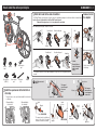
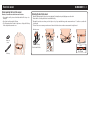
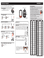
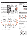
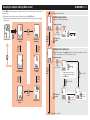
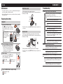
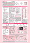
CC-RD420DW ENG 1
CATEYE STRADA
DIGITAL WIRELESS
CYCLOCOMPUTER
CC-RD420DW
Before using the computer, please thoroughly read
this manual and keep it for future reference.
Please visit our website, where detailed instructions with movies are available and the instruction
manual can be downloaded.
The sensor ID was synchronized with this unit before shipment. It is not necessary to synchronize the sensor ID.
*In combination with the optional speed sensor (ISC-10), this
unit is capable of receiving and displaying up to 3 signals of the
current speed, cadence, and heart rate.
Warning / Caution
Automatic recognition of the speed sensor ID
• Pace maker users should never use this device.
• Do not concentrate on the computer while riding. Ride safely!
• Install the magnet, sensor, and bracket securely. Check these periodically.
• If a child swallows a battery, consult a doctor immediately.
• Do not leave the computer in direct sunlight for a long period of
time.
• Do not disassemble the computer.
• Do not drop the computer to avoid malfunction or damage.
• When using the computer installed on the bracket, change the
MODE by pressing on the three dots below the screen. Pressing
hard on other areas can result in malfunction or damage to the
computer.
• Be sure to tighten the dial of the FlexTight™ bracket by hand. Tightening it strongly using a tool, etc. may damage the screw thread.
• Stop using the unit if you have skin irritation with the HR strap or
electrode pad.
• Do not twist or pull strongly the HR strap.
• The HR strap may deteriorate due to long-term use. Replace the HR
strap if it has frequent measurement errors.
• When cleaning the computer, bracket and sensor, do not use thinners, benzene, or alcohol.
• Dispose of used batteries according to local regulations.
• LCD screen may be distorted when viewed through polarized sunglass lenses.
The speed sensor has its own ID, and the computer measures in synchronization with the ID.
Two speed-sensor IDs can be registered to one computer, which can
automatically identify two speed sensors once their IDs are registered
in advance.
As a tire circumference is set to the speed sensor ID, wheel selection
by manual operation is no longer required, which was necessary with
conventional units.
*The speed sensor currently recognized is indicated with a sensor
icon ( or ) on the screen.
2.4GHz digital wireless system
Each sensor adopts the 2.4GHz digital wireless technology, which is
used for wireless LAN, etc. This technology practically eliminates interference from any external noise and cross-talk with other wireless
computer users during measurement, and enables it to record and
store highly reliable data. However, it suffers interference in the following places and/or environments, which may result in an incorrect
measurement.
*Careful attention is required especially while checking the sensor
ID.
• TV, PC, radios, motors/engines, or in cars and trains.
• Railroad crossings and near railway tracks, around television transmitting stations and radar bases.
• Other wireless computers or digitally controlled lights.
• In the Wi-Fi environment.
Procedure of automatic recognition
When the computer changes to the power saving screen, and then returns to the measurement screen, automatic recognition of the speed
sensor ID is performed in the following procedure.
1The computer searches the speed sensor ID signal, which had
been synchronized immediately before.
2Once the sensor signal is received, the sensor icon for the speed
sensor lights up, and the computer starts the measurement.
When the speed sensor ID signal which had been synchronized immediately before, cannot be received another sensor signal is searched.
3When the computer receives another sensor signal, the sensor icon for
the other sensor lights up on the screen, and starts the measurement.
When another speed sensor ID signal cannot be received, the
original sensor signal is searched again.
The computer repeats synchronization through the procedure described
above even if it fails in synchronization for some reason, such as communication failure; in such cases however, it takes time for recognition.
*When the computer does not receive any signal from the sensor for
10 minutes, it will change to the power-saving screen. When such a
condition lasts another 1 hour, it will get into the sleep state.
Switching the ID by manual operation
The speed sensor ID can be forced to change manually, according to
the menu screen “Setting the tire circumference”. Use this operation
in the following cases.
• When the computer cannot recognize the intended sensor signal,
since the 2 registered speed sensors are nearby and both are sending a sensor signal.
• When you want to switch the speed sensor ID immediately.
*Once you switch the speed sensor ID by manual operation, the computer continues to search only the speed sensor ID you switched
when returning to the measurement screen. When the computer
cannot receive any sensor signal in 10 minutes, the power-saving
mode is activated, and the computer changes to the power saving
screen. The computer searches through the procedure of automatic
recognition when it returns to the measurement screen.
CC-RD420DW ENG 2
How to install the unit on your bicycle
1
1Attach the bracket to the stem or handlebar
Remove/Install
the computer
The FlexTight™ bracket can be attached to either the stem or the handlebar, depending on how the bracket fits into the bracket band.
Caution: Be sure to tighten the dial of the FlexTight™ bracket by hand.
Tightening it strongly using a tool, etc. may damage the screw thread.
When attaching the FlexTight™ bracket to the stem :
Bracket band
2
Click
Bracket rubber pad
Dial
Stem
Bracket
When attaching the FlexTight™ bracket to the handlebar :
Bracket band
While supporting it by hand,
Bracket rubber pad
Handlebar
Cut
Bracket
band
Bracket
Dial
Bracket rubber
pad
Bracket
*To mount the bracket to an aero-shaped handlebar or larger stem, use the optional nylon ties
bracket.
Speed sensor
(SPD-10)
Sensor rubber
pad
Nylon ties
(x 2)
Magnet
Install the sensor and
magnet
The magnet
passes through
the sensor
zone.
chain stay
* The speed sensor can be used either installed to the front fork
or chain stay.
When installing to
the front fork:
When installing to
the chain stay:
Push it out as if lifting
the front up
Speed sensor
Magnet
2Install the speed sensor to the front fork or
Caution:
Round off the cut
edge of the bracket
band to prevent
injury.
Speed sensor
Spoke
Magnet
3 mm
SENSOR ZONE
Speed
sensor
Magnet
Speed
sensor
The clearance
between the sensor and magnet is
3 mm or less.
Pull
securely
To the SENSOR ZONE
* The magnet may be installed anywhere on the spoke if the above
installation conditions are satisfied.
Magnet
SENSOR ZONE
Sensor
rubber pad
Cut
Nylon ties
CC-RD420DW ENG 3
Heart rate sensor
Before wearing the heart rate sensor
Warning: Pace maker users should never use this device.
• Stop using the unit if you have skin irritation with the HR strap or electrode pad.
• Do not twist or pull strongly the HR strap.
• The HR strap may deteriorate due to long-term use. Replace the HR strap
if it has frequent measurement errors.
Wearing the heart rate sensor
*Adjust the HR strap length to fit your chest size (underbust). Fastening the strap too tightly may cause discomfort.
*Ensure that the electrode pad is in direct contact with the body.
*Wearing the heart rate sensor when your skin is dry or on top of your undershirt may produce measurement errors. To avoid errors, moisten the
electrode pad.
*The heart rate sensor consumes power when worn. Remove the heart rate sensor whenever measurement is not performed.
Heart rate sensor
Heart rate
sensor
HR strap
Back
Push it in until it clicks.
Hook
HR strap
Electrode pad
CC-RD420DW ENG 4
Preparing the computer
Perform the following formatting operation, when you use the unit for the
first time or restore the unit to the condition before shipment.
1Format (initialize)
Press the MENU button on the back of the computer and the AC button simultaneously.
AC
Tire circumference
Battery case cover
MENU
AC
2Select the speed unit
MENU
Select “km/h” or “mph”.
Register the
setting
km/h ↔ mph
Dot section
MENU
MODE
3Enter the tire circumference
Operation test
Enter the sensor-installed tire circumference in mm.
*Use “Tire circumference reference table” as a
guide.
Move digIncrease
Register
its (Press
the value
the setting
& hold)
MENU
MODE
Pressing and holding the MODE button switches
the display to “Displayed time”, “Hour”, and “Minute” in order.
12h ↔ 24h
Switch the
or increase the
screen or
value
move digits
MODE
Test the functioning of the speed sensor and the heart rate sensor.
Speed sensor
After installed, check that the computer displays
the speed by gently turning the wheel to which the
magnet is installed. When it is not displayed, check
the installation conditions and again (page 2).
MODE
4Set the Clock
MODE
Display format
Heart rate sensor
MODE
Hour
Minute
(heart
1Press the MODE button to display
rate).
2It operates normally if the computer displays the
heart rate after you wear the heart rate sensor.
5Press the MENU button to complete setting
Register the setting
(Finish)
MENU
*Even if the heart rate sensor is not
worn, a heart rate signal is transmitted by rubbing both electrode
pads with your thumb. Use this as a
simplified method.
Electrode pad
You can find the tire circumference (L) of your tire size in the chart below, or actually measure the tire circumference (L) of your bicycle.
• How to measure the tire circumference (L)
For the most accurate measurement, do a wheel
roll out. With the tires under proper pressure, place
the valve stem at the bottom. Mark the spot on the
floor and with the rider’s weight on the bike, roll
L mm
exactly one wheel revolution in a straight line (until
the valve comes around again to the bottom). Mark where the valve
stem is and measure the distance.
*Measure the tire to which the sensor is installed.
• Tire circumference reference table
*Generally, the tire size or ETRTO is indicated on the side of the tire.
ETRTO
47-203
54-203
40-254
47-254
40-305
47-305
54-305
28-349
37-349
32-369
40-355
47-355
32-406
35-406
40-406
47-406
50-406
28-451
37-451
37-501
40-501
47-507
50-507
54-507
25-520
28-540
32-540
25-559
32-559
37-559
40-559
47-559
50-559
54-559
Tire size
L (mm)
12x1.75
935
12x1.95
940
14x1.50
1020
14x1.75
1055
16x1.50
1185
16x1.75
1195
16x2.00
1245
16x1-1/8
1290
16x1-3/8
1300
17x1-1/4 (369) 1340
18x1.50
1340
18x1.75
1350
20x1.25
1450
20x1.35
1460
20x1.50
1490
20x1.75
1515
20x1.95
1565
20x1-1/8
1545
20x1-3/8
1615
22x1-3/8
1770
22x1-1/2
1785
24x1.75
1890
24x2.00
1925
24x2.125
1965
24x1(520)
1753
24x3/4 Tubuler 1785
24x1-1/8
1795
24x1-1/4
1905
26x1(559)
1913
26x1.25
1950
26x1.40
2005
26x1.50
2010
26x1.75
2023
26x1.95
2050
26x2.10
2068
ETRTO
57-559
58-559
75-559
28-590
37-590
37-584
20-571
23-571
25-571
40-590
40-584
25-630
28-630
32-630
37-630
18-622
19-622
20-622
23-622
25-622
28-622
30-622
32-622
35-622
38-622
40-622
42-622
44-622
45-622
47-622
54-622
60-622
Tire size
26x2.125
26x2.35
26x3.00
26x1-1/8
26x1-3/8
26x1-1/2
650C Tubuler
26x7/8
650x20C
650x23C
650x25C
26x1(571)
650x38A
650x38B
27x1(630)
27x1-1/8
27x1-1/4
27x1-3/8
700x18C
700x19C
700x20C
700x23C
700x25C
700x28C
700x30C
700x32C
700C Tubuler
700x35C
700x38C
700x40C
700x42C
700x44C
700x45C
700x47C
29x2.1
29x2.3
L (mm)
2070
2083
2170
1970
2068
2100
1920
1938
1944
1952
2125
2105
2145
2155
2161
2169
2070
2080
2086
2096
2105
2136
2146
2155
2130
2168
2180
2200
2224
2235
2242
2268
2288
2326
CC-RD420DW ENG 5
Operating the computer [Measuring screen]
Speed sensor signal icon
It flashes in synch with a speed sensor signal.
Current speed
0.0 (4.0) – 105.9 km/h
[0.0 (3.0) – 65.9 mph]
*“S” icon is displayed when
displaying current speed at
the bottom.
Pace arrow
Indicates if the current speed is faster or slower
than the average speed. ( Faster, Slower)
Starting/Stopping measurement
MODE operation when
the computer is mounted on the bracket
Click
Measurements start automatiSTART
STOP
cally when the bicycle is in
motion.
During measurement, km/h or
mph flashes.
Start measurement Stop measurement
Speed unit
Sensor icon
The speed sensor currently synchronized is displayed.
Upper display selection
Option *1
Speed sensor
(ISC-10)
HR sensor signal icon
It flashes in synch with a heart rate sensor signal.
*The position changes according to the heart rate
display position.
The heart rate ( ) or the cadence ( ) can be switched to the upper display to monitor it constantly.
Setting method See “Changing the computer settings: Setting the upper
display” (Page 6).
*The optional speed sensor (ISC-10) is required to measure the cadence.
Current
speed
Switching computer function
Pressing the MODE button switches the measurement data at the bottom in the order shown in the following figure.
Heart rate
Elapsed Time
0:00’00” – 9:59’59”
MODE
Heart rate
0(30) – 199 bpm
(Cadence *1)
MODE
Trip Distance
0.00 – 999.99 km
[mile]
MODE
Heart rate/Current speed
Heart
rate
Current speed
Resetting data
Trip Distance-2
0.00 – 999.99 km
[mile]
MODE
Cadence (*)
MODE
Pressing and holding the MODE button on the measure(Press
ment screen resets any measurement data, except the
& hold)
total distance (Odo) and trip distance-2 (Dst2).
*The total distance (Odo) is not reset.
MODE
• Resetting separately the trip distance-2
Pressing and holding the MODE button with the trip distance-2 (Dst2)
displayed resets only the data of the trip distance-2.
Power-saving function
Clock
0:00 – 23:59
MODE
Total Distance
0 – 99999 km[mile]
MODE
Maximum Speed
0.0(4.0) – 105.9 km/h
[0.0(3.0) – 65.9 mph]
*1 In combination with the optional speed sensor (ISC-10), it displays the cadence.
*2When Tm exceeds about 27 hours, or Dst exceeds 999.99 km, .E will appear. Reset the data.
MODE
Average Speed (*2)
0.0 – 105.9 km/h
[0.0 – 65.9 mph]
If the computer has not received a signal for 10 minutes, power-saving
screen will activate and only the clock will be displayed.
With such a screen, pressing the MODE button returns to the measurement screen.
*If another 60 minutes of inactivity elapses in the power-saving screen,
only the speed unit is displayed on the screen.
MODE
10 minutes
Measuring screen
60 minutes
Power-saving screen
Sleep screen
CC-RD420DW ENG 6
Changing the computer settings [Menu screen]
Pressing MENU on the measurement screen changes to the menu screen. Various settings can be changed on
the menu screen.
*After changes are made, be sure to register the setting(s) by pressing the MENU button.
*Leaving the menu screen without any operation for 1 minutes returns to the measurement screen, and changes are not saved.
From “Selecting the measurement unit”
Setting the upper display
Select the function for the upper display.
Changing the settings
MODE
(Press & hold)
MODE
Measuring screen
MENU
Setting the upper
display
Setting the tire
circumference
MODE
MODE
MODE
Register the
setting
MENU
Setting the tire circumference
MODE
Manually switch the speed sensor /
, and enter the circumference size assigned to each sensor.
*For the tire circumference, see “Tire circumference” (page 4).
Changing the settings
MENU
MODE
↔
(Press & hold)
Selecting the
measurement unit
Searching for
sensor ID
MODE
*To change only the speed sensor,
select the speed sensor used, and
press MENU to set.
MODE
MODE
MODE
(Press & hold)
MODE
(Press & hold)
MODE
Register the
setting
MODE
MENU
Entering the total
distance
Setting the clock
Move digits
(Press & hold)
0100 – 3999
MODE
To “Searching for sensor ID”
MODE
Increase
the value
CC-RD420DW ENG 7
Changing the computer settings [Menu screen]
From “Setting the tire circumference”
From “Setting the clock”
Searching for sensor ID
Entering the total distance
Search the heart rate and speed sensor IDs.
*The sensor ID was synchronized with this unit before shipment.
Search the sensor ID only when a new sensor is used.
Enter the total distance.
Once you enter any value to the total distance, you can start from the value you entered. Use
this function when you renew and/or reset your unit.
Changing the settings
Changing the settings
SP1
MODE
(Press & hold)
SP2
HR
MODE
MODE
(Press & hold)
Register the
setting
RESET
In case of HR
Selecting the measurement unit
RESET
In case of cancellation or 5 minutes
of inactivity
Select the speed unit (km/h or mph).
Changing the settings
MODE (Press
& hold)
Setting the clock
MODE
(Press & hold)
Set the clock.
Changing the settings
Register the
setting
MODE
12h ↔ 24h
(Press & hold)
(Press & hold)
MODE
(Press & hold)
MODE
MODE
Hour
MENU
0 – 23
[1 – 12]
Minute
Switch the screen
(press & hold)
MODE
MENU
MODE
MODE
Register the
setting
To “Entering the total distance”
MODE
MENU
In case of SP1
and SP2
MENU
Move digits
(press & hold)
00000 – 99999
MODE
Register the
setting
MODE
MODE
(Press & hold)
MODE
Increase
the value
MODE
00 – 59
Increase
the value
To “Setting the upper display”
km/h ↔ mph
MODE
CC-RD420DW ENG 8
In use
Heart rate sensor
Troubleshooting
• To clean the computer or accessories, use diluted neutral detergent on
a soft cloth, and wipe it off with a dry cloth.
• Since the HR strap directly touches your skin, keep it clean by washing
off any dirt after use.
*When the heart rate flashes, replace the battery.
Insert new lithium batteries (CR2032) with the (+) sign upward, and close
the battery cover firmly.
The current speed / heart rate cannot be measured.
Close
Replacing the battery
Open
Battery
case
cover
TO
P
When (battery icon) is turned on, replace the battery. Install a new lithium
battery (CR2032) with the (+) side facing
upward.
Is there any problem in searching the sensor ID?
P
TO
*When the current speed flashes, replace the speed sensor battery.
Insert new lithium batteries (CR2032) with the (+) sign upward, and close
the battery cover firmly.
CR2032
CR2032
2Press the AC button on the back of
AC
the computer (Restarting operation)
3Set the Clock
Pressing and holding the MODE button
switches the display to “Displayed time”,
“Hour”, and “Minute” in order.
MODE
IN
Does the computer or sensor indicate when to replace the battery?
Open
Nothing is displayed by pressing the button.
Replace the computer battery according to the procedure
specified in the section “Replacing the battery”.
Incorrect data appear.
Restart according to the procedure specified in the section
“Replacing the battery / Computer, steps 2 to 4”.
The measurement data is wrong. (The maximum speed is too high,
etc.)
Are there any objects emitting electromagnetic waves (railway
tracks, transmitting stations for television, Wi-Fi environment, etc.)
nearby?
Keep the unit away from any object that may be the cause.
Perform the resetting operation in the case of invalid data.
MODE
Register the setting
(Finish)
MENU
Display format
Switch the screen
or move digits
4Press the MENU button to complete setting
CO
Search the sensor ID according to the procedure specified in the section “Changing the computer setting /
Searching for sensor ID” (Page 7).
Replace with new batteries according to the procedure
specified in the section “Replacing the battery.”
Close
*After replacement, check the position in respect to the magnet.
*Reset the sensor by pressing RESET button when you replace the sensor battery.
*When restarting, the speed unit, sensor
ID, sensor currently synchronized, tire
circumference, upper display setting,
and total distance are retained.
12h ↔ 24h
or increase the value
Replace it with a new HR strap.
Common
Waterproof
inner cap
Adjust the electrode pad to have a good contact with the
body.
Is the electrode pad overly worn and damaged after long use?
Speed sensor
Click
TOP
*Reset the sensor by pressing RESET button when you replace the sensor battery.
Is the heart rate sensor attached securely to your body?
HR
1Replace the lithium battery
Check that the clearance between the sensor and magnet is
not too large. (Clearance: within 3 mm)
Check that the magnet passes through the sensor zone correctly.
Adjust the positions of the magnet and sensor.
CR2032
Computer
*Press the top edge of
waterproof inner cap
to remove it. Install
the cap with the “TOP”
faced upward.
N
COI
SPD
Maintenance
Hour
Minute
CC-RD420DW ENG 9
In use
Specification
Spare accessories
CR2032 x 1 / Approx. 6 months
(When using 1 hour/day)
Battery
Heart rate
CR2032 x 1 / Approx. 1 year
/ Battery life
sensor :
(When worn about 1 hour per day)
CR2032 x 1 / Approx. 1 year
Speed sensor :
(When using 1 hour/day)
* The factory-loaded battery life might be shorter than the above-mentioned
specification.
Controller
1-chip microcomputer (Crystal controlled oscillator)
Display
Liquid crystal display
Sensor
No contact magnetic sensor
Sensor signal
transmission
2.4 GHz ISM Band
and reception
Communication 5 m (It may change depending on the environmental condirange
tions, including weather.)
Tire circumfer- 0100 mm - 3999 mm
ence range
(Initial value : 2096 mm)
0 °F - 104 °F (0 °C - 40 °C) (This product will not display
Working temper- appropriately when exceeding the Working Temperature
ature
range. Slow response or black LCD at lower or higher temperature may happen respectively.)
1-53/64” x 1-7/32” x 5/8”
Computer :
(46.5 x 31 x 16 mm) / 0.72 oz (20.3 g)
Dimensions/
Heart rate
1-7/32” x 2-29/64” x 33/64”
weight
sensor :
(31 x 62.5 x 13.2 mm ) / 0.54 oz (15.4 g)
1-39/64” x 1-51/64” x 15/32”
Speed sensor :
(40.8 x 45.7 x 12.1 mm) / 0.43 oz (12.3 g)
* The specifications and design are subject to change without notice.
Standard accessories
Computer :
Limited warranty
2-Year: Computer, Heart rate sensor and Speed sensor
(Accessories and Battery Consumption excluded)
CatEye cycle computers are warranted to be free of defects from materials and
workmanship for a period of two years from original purchase. If the product
fails to work due to normal use, CatEye will repair or replace the defect at no
charge. Service must be performed by CatEye or an authorized retailer. To
return the product, pack it carefully and enclose the warranty certificate (proof
of purchase) with instruction for repair. Please write or type your name and
address clearly on the warranty certificate. Insurance, handling and transportation charges to CatEye shall be borne by person desiring service.
For UK and REPUBLIC OF IRELAND consumers, please return to the place of
purchase. This does not affect your statutory rights.
2-8-25, Kuwazu, Higashi Sumiyoshi-ku, Osaka 546-0041 Japan
Attn: CATEYE Customer Service Section
Phone : (06)6719-6863
Fax : (06)6719-6033
E-mail : [email protected]
URL : http://www.cateye.com
[For US Customers]
CATEYE AMERICA, INC.
2825 Wilderness Place Suite 1200, Boulder CO80301-5494 USA
Phone : 303.443.4595
Toll Free : 800.5CATEYE
Fax
: 303.473.0006
E-mail
: [email protected]
1603680
(SPD-10)
1603685
1600280N
1602193
(SPD-10)
Parts kit
Speed
sensor
Bracket
band
Bracket
1699691N
1665150
1603590
1603595
Wheel
magnet
Lithium
battery
CR2032
Optional accessories
1602980
1603585
Nylon tie
bracket
Speed
sensor
(ISC-10)
(HR-10)
Heart rate
sensor kit
HR strap