1
Mercury, Mercury Marine, MerCruiser, Mercury MerCruiser, Mercury Racing, Mercury Precision Parts,
Mercury Propellers, Mariner, Quicksilver, #1 On The Water, Alpha, Bravo, Pro Max, OptiMax, Sport-Jet,
K-Planes, MerCathode, RideGuide, SmartCraft, Zero Effort, M with Waves logo, Mercury with Waves
logo, and SmartCraft logo are all registered trademarks of Brunswick Corporation. Mercury Product
Protection logo is a registered service mark of Brunswick Corporation.
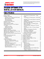
200/225 OPTIMAX DTS
INSTALLATION MANUAL
Table of Contents
Notice to Installer ................................................... 2
Installation Information .......................................... 2
Avoiding Loss of Throttle and Shift Control.......2
Before Starting the Engine................................2
Fuel Requirements............................................2
Oil Recommendation.........................................2
Avoiding Fuel Flow Restriction .............................. 2
Electric Fuel Pump ................................................ 3
Boat Horsepower Capacity .................................... 3
Selecting Accessories For Your Outboard ............ 3
Fuel Tanks ............................................................. 3
Portable Fuel Tank ........................................... 3
Permanent Fuel Tank ....................................... 3
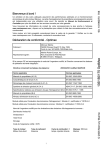
Installation Specifications ...................................... 4
Lifting the Outboard ............................................... 4
Applying Counter Rotation Decals ........................ 5
Steering Cable - Starboard Side Routed Cable .... 5
Steering Link Rod Fasteners ................................. 6
Determining Recommended Outboard Mounting
Height .................................................................... 7
Drilling Outboard Mounting Holes ......................... 8
Front Clamp Assembly .......................................... 9
Removal ............................................................ 9
Installation ......................................................... 9
Wiring and Installation ......................................... 11
Wire Color Code Abbreviations.......................11
Installation Guidelines for DTS System
Components....................................................11
Data Harness Pulling Procedure.....................11
Junction Box (If Equipped)...............................12
Non-Mercury Marine Provided Ignition Switch.12
Wiring Accessories..........................................13
System Wiring Reference Points.....................13
Page 1 / 42
Connecting 14 Pin Data Harness - Single
Engine..............................................................14
Connecting 14 Pin Data Harness - Dual Engine
.........................................................................15
Installing DTS Command Module and Harness Single Engine...................................................16
Installing DTS Command Module and Harness Dual Engine/Single Helm.................................20
Battery Cable Size For Outboard Models........21
Battery Information..........................................23
Connecting Battery Cables and DTS Power
Harness...........................................................23
Connecting Fuel Tank, Oil Tank and Speed
Sensor.............................................................26
Switched 12V Accessory Connection..............28
DTS Wiring - Single Engine.............................29
DTS Wiring - Dual Engine................................31
System Wiring Installation Checklist................32
Fuel Hose and Oil Hose Connections ................. 32
Fuel Hose Connection .................................... 32
Filling the Fuel System ........................................ 33
Filling the Oil System .......................................... 33
Priming Oil Injection Pump .................................. 34
Purging Air From the Engine Oil Tank ................. 36
Propeller Installation ............................................ 36
Trim In Pin ........................................................... 37
Paddle Wheel Speed Sensor Installation (If
Equipped) ............................................................ 38
Parts Provided ................................................ 38
Selecting Location .......................................... 38
Transom Angle Requirements ........................ 39
Installing Bracket ............................................ 39
Routing the Cable ........................................... 40
Installing and Removing the Paddle Wheel .... 41
Wiring Connections ......................................... 41
Template - Paddle Wheel Speed Sensor ....... 42
© 2004 Mercury Marine
90-10234050 APRIL 2004
200/225 OPTIMAX DTS
Notice to Installer
This Product Requires Electronic Calibration Before Use.
Installation of this product will require electronic calibration. This calibration must not be
attempted by anyone other than the Original Equipment Manufacturer (OEM) or a
Mercury technician trained in Digital Throttle and Shift systems (DTS) at an authorized
Mercury dealership. Improper installation and calibration of the DTS product will result in
a system which is inoperable or unsafe for use.
Installation Information
Avoiding Loss of Throttle and Shift Control
! WARNING
To avoid the possibility of serious injury or death from loss of boat control, do not splice
or probe into any wire insulation of the DTS system. Splicing or probing will damage
the wire insulation allowing water to enter the wiring. Water intrusion may lead to wiring
failure and loss of throttle and shift control.
Before Starting the Engine
! CAUTION
Avoid engine damage. Prime the oil injection pump on new or rebuilt engines and after
maintenance is performed on the oiling system.
Refer to Priming the Oil Injection Pump for instructions.
Fuel Requirements
Do not use pre-mixed gas and oil in this engine. The engine automatically receives extra
oil during engine break-in. Use a fresh supply of the recommended gasoline during engine
break-in and after engine break-in.
Oil Recommendation
Recommended Oil
OptiMax Oil or Premium Plus 2-Cycle TC-W3 Outboard Oil
OptiMax Oil or Premium Plus TC-W3 is a higher grade oil that provides increased
lubrication and extra resistance to carbon buildup when used with good or varying grades
of gasoline.
IMPORTANT: Oil must be NMMA certified TC-W3 2-Cycle oil.
Periodically consult with your dealer to get the latest gasoline and oil recommendations.
If Mercury Precision or Quicksilver 2-Cycle Outboard Oil is not available, substitute
another brand of 2-Cycle outboard oil that is NMMA Certified TC-W3. The use of an
inferior 2-Cycle outboard oil can reduce engine durability. Damage from use of inferior oil
may not be covered under the limited warranty.
Avoiding Fuel Flow Restriction
IMPORTANT: Adding components to the fuel supply system (filters, valves, fittings, etc.)
may restrict the fuel flow. This may cause engine stalling at low speed, and/or a lean fuel
condition at high RPM that could cause engine damage.
Page 2 / 42
90-10234050
200/225 OPTIMAX DTS
Electric Fuel Pump
The fuel pressure must not exceed 28 kPa (4 psi). If necessary, install a pressure
regulator.
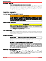
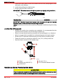
Boat Horsepower Capacity
! WARNING
Using an outboard that exceeds the maximum horsepower limit of a boat can: 1) cause
loss of boat control 2) place too much weight at the transom altering the designed
flotation characteristics of the boat or 3) cause the boat to break apart particularly
around the transom area. Overpowering a boat can result in serious injury, death or
boat damage.
Do not overpower or overload your boat. Most boats will carry a required capacity plate
indicating the maximum acceptable power and load as determined by the manufacturer
following certain federal guidelines. If in doubt, contact your dealer or the boat
manufacturer.
U.S. COAST GUARD CAPACITY
MAXIMUM HORSEPOWER XXX
MAXIMUM PERSON
CAPACITY (POUNDS)
XXX
MAXIMUM WEIGHT
CAPACITY
XXX
ob00306
Selecting Accessories For Your Outboard
Genuine Mercury Precision or Quicksilver Accessories have been specifically designed
and tested for your outboard. These accessories are available from Mercury Marine
dealers.
! WARNING
Check with your dealer before installation of accessories. The misuse of acceptable
accessories or the use of unacceptable accessories can result in serious injury, death,
or product failure.
Some accessories not manufactured or sold by Mercury Marine are not designed to be
safely used with your outboard or outboard operating system. Acquire and read the
installation, operation, and maintenance manuals for all your selected accessories.
Fuel Tanks
Portable Fuel Tank
Select a suitable location in the boat within the engine fuel line length limitations and
secure the tank in place.
Permanent Fuel Tank
Permanent fuel tanks should be installed in accordance with industry and federal safety
standards, which include recommendations applicable to grounding, anti-siphon
protection, ventilation, etc.
90-10234050
Page 3 / 42
200/225 OPTIMAX DTS
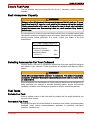
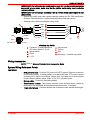
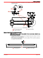
Installation Specifications
a
a
b
Ob01471
a - Minimum transom opening
b - Engine center line for dual engine - 66.0 cm (26 in.)
Minimum Transom Opening
Single engine
99.0 cm (39 in.)
Dual engine
165.0 cm (65 in.)
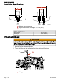
Lifting the Outboard
! WARNING
Avoid possible serious injury or death. Before lifting the outboard, verify that the lifting
ring is threaded into the flywheel for a minimum of five turns and that the hoist has the
correct lifting capacity for the engine weight.
1. Remove the cowl from the outboard.
2. Thread the lifting eye into the flywheel hub for a minimum of five turns.
a
or138
a - Lifting eye
Page 4 / 42
90-10234050
200/225 OPTIMAX DTS
3. Connect a hoist to the lifting eye.
4. Lift the outboard and place it on the boat transom.
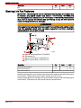
Applying Counter Rotation Decals
IMPORTANT: For dual outboard counter rotation installation, the left- hand rotation
outboard is generally placed on the port sided of the transom.
1. Apply counter rotation decal (supplied with left-hand rotation outboard) onto
right-hand rotation outboard.
2. Match decal placement with left-hand rotation outboard.
Steering Cable - Starboard Side Routed Cable
1. Lubricate O-ring seal and entire cable end.
95
3724
Tube Ref. No.
95
Description
2-4-C with Teflon
Where Used
Part Number
O-ring seal and the entire cable end.
92-802859A1
2. Insert steering cable into tilt tube.
3725
3. Torque nut to specification.
3727
90-10234050
Page 5 / 42
200/225 OPTIMAX DTS
Description
Nm
Nut
47.5
lb. in.
lb. ft.
35
Steering Link Rod Fasteners
IMPORTANT: The steering link rod that connects the steering cable to the engine must
be fastened using special washer head bolt ("a" - Part Number 10-849838) and
self-locking nylon insert locknuts ("c" & "d" - Part Number 11-826709113). These locknuts
must never be replaced with common nuts (non-locking) as they will work loose and
vibrate off freeing the link rod to disengage.
! WARNING
Disengagement of a steering link rod can result in the boat taking a full, sudden, sharp
turn. This potentially violent action can cause occupants to be thrown overboard
exposing them to serious injury or death.
a
b
c
d
abcd-
ob00676
Special washer head bolt (10-849838)
Flat washer (2)
Nylon insert locknut (11-826709113)
Nylon insert locknut (11-826709113)
Description
Nm
Special washer head bolt
27
20
Nylon insert locknut "d"
27
20
Nylon insert locknut "c"
lb. in.
lb. ft.
Tighten until seats, then back off 1/4 turn
Assemble steering link rod to steering cable with two flat washers and self-locking nylon
insert locknut. Tighten locknut until it seats, then back nut off 1/4 turn.
Assemble steering link rod to engine with special washer head bolt and self-locking nylon
insert locknut. First torque bolt, then torque locknut to specifications.
Page 6 / 42
90-10234050
200/225 OPTIMAX DTS
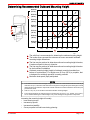
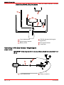
Determining Recommended Outboard Mounting Height
63.5 cm
(25 in.)
e
60.9 cm
(24 in.)
b
58.4 cm
(23 in.)
c
56.0 cm
(22 in.)
e
53.3 cm
(21 in.)
a
d
50.8 cm
(20 in.)
48.2 cm
(19 in.)
10
20
30
40
50
60
70
80
f
3728
a - The solid line is recommended to determine the outboard mouting height.
b - The broken lines represent the extremes of known successful outboard
mounting height dimensions.
c - The line may be prefered to determine outboard mounting height dimesion,
if maximum speed is the only objective.
d - The line may be prefered to determine outboard mounting height dimesion
for dual outboard installation.
e - Outboard mounting height (height of outboard mounting brackets from
bottom of boat transom). For heights over 56.0 cm (22 in.) a propeller, that
is designed for surfacing operation is usually prefered.
f - Maximum boat speed (mph) anticipated.
NOTICE
1.
The outboard should be mounted high enough on the transom so that exhaust relief hole will stay at
least 25.4 mm (1 in.) above the water line when the engine is running at idle speed. Having the exhaust
relief hole above the water line will prevent exhaust restrictions. Exhaust restrictions will result in poor
performance at idle.
2.
Add 12.7 cm (5 in.) for XL models to the listed outboard mounting heights.
3.
The mounting height of the outboard must not exceed 63.5 cm (25 in.) for L models, 76 cm (30 in.)
for XL models. Mounting the outboard higher may cause damage to the gearcase components.
Increasing the mounting height will usually:
• Less steering torque.
• Increase top speed.
• Increase boat stability.
• Cause propeller to break loose during planning.
90-10234050
Page 7 / 42
200/225 OPTIMAX DTS
Drilling Outboard Mounting Holes
IMPORTANT: Before drilling any mounting holes, carefully read Determining
Recommended Outboard Mounting Height and install outboard to the nearest
recommended mounting height.
1. Use transom drilling fixture or attach (tape) engine mounting template to boat
transom.
ob01472
2. Mark and drill four 13.5 mm (17/32 in.) mounting holes.
3973
3. Apply marine sealer to shanks of bolts, not the threads.
Page 8 / 42
90-10234050
200/225 OPTIMAX DTS
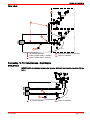
4. Fasten outboard with provided mounting hardware.
a
e
b
d
c
3729
a - Flat washer (4)
b - 1/2 in. diameter bolt (4)
c - Shank of bolt
d - Locknut (4)
e - Flat washer (4)
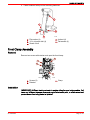
Front Clamp Assembly
Removal
Remove two screws with retainer and open the front clamp.
a
a
b
c
3765
a - Screws (2)
b - Retainer
c - Clamp
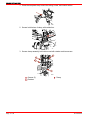
Installation
IMPORTANT: Sufficient slack must exist in engine wiring harness battery cables, fuel
hose, and oil hoses between clamp and engine attachment point, to relieve stress and
prevent hoses from being kinked or pinched.
90-10234050
Page 9 / 42
200/225 OPTIMAX DTS
1. Place the neoprene wrap around the wiring, hoses, and control cables.
3766
2. Secure both halves of clamp with cables ties.
3764
3. Secure clamp assembly into bottom cowl with retainer and two screws.
a
a
b
c
3765
a - Screws (2)
b - Retainer
Page 10 / 42
c - Clamp
90-10234050
200/225 OPTIMAX DTS
Wiring and Installation
Wire Color Code Abbreviations
Wire Color Abbreviations
BLK
Black
BLU
Blue
BRN
Brown
GRY
Gray
GRN
Green
ORN or ORG
Orange
PNK
Pink
PPL or PUR
Purple
RED
Red
TAN
Tan
WHT
White
YEL
Yellow
LT or LIT
Light
DK or DRK
Dark
Installation Guidelines for DTS System Components
! WARNING
To avoid the possibility of serious injury or death from loss of boat control, do not splice
or probe into any wire insulation of the DTS system. Splicing or probing will damage
the wire insulation allowing water to enter the wiring. Water intrusion may lead to wiring
failure and loss of throttle and shift control.
DATA HARNESS
! WARNING
To avoid the possibility of serious injury or death from loss on boat control, do not pull
on cable connectors when pulling cable into boat. Observe correct pulling procedure.
Pulling on connectors can loosen terminals resulting in open or poor electrical
connections. Open or poor electrical connections may result in loss of throttle and shift
control.
CONNECTORS
IMPORTANT: Connectors should never have to be forced into the receptacle. Ensure
that connectors are free of any lubricant or dielectric grease before installation. When the
connector is properly aligned, it will only take a small amount of pressure to insert it into
the receptacle. Rotate the locking collar to secure the electrical connection.
NOTE: Connect only one data harness of the required length between the engine and
helm. If a data harness is too short, do not connect multiple harnesses together to make
up the required length. For installations requiring a data harness length longer than
12.2 m (40 ft.), contact Mercury Marine for more information.
Data Harness Pulling Procedure
IMPORTANT: Do not route data harness near engine ignition components (coils, spark
plug leads, and spark plugs), high power VHF coax or radios. An electrical field generated
from these components could cause interference with data transmission.
IMPORTANT: Do not route data harness near sharp edges, hot surfaces or moving parts.
Fasten cables away from any sharp edges, fasteners or objects that could wear into the
harness.
IMPORTANT: Avoid sharp bends in the data harness. Minimum bend radius should be
7.6 cm (3 in.) for the final wiring installation.
90-10234050
Page 11 / 42
200/225 OPTIMAX DTS
1. Inspect the routing path to make sure surfaces are free of any sharp edges or burrs
that could cut the harness.
2. Install cable pulling tool to data harness.
3. Secure pulling tool with 2 cable ties.
IMPORTANT: The cables ties must be tight to prevent any slipping during installation.
3836
Data Cable Puller
91-888462A1
IMPORTANT: Carefully inspect data harness pins to ensure all pins are securely
fastened to data harness connector end following installation.
NOTE: Data harness should be secured with mounting clips or cable ties along the routing
path.
Junction Box (If Equipped)
•
•
•
•
•
•
Although the junction box connections are watertight, it is recommended that the
junction box be mounted in an area that stays relatively dry.
Mount in an area where the wiring connection will not get stepped on or disturbed.
Mount in an area that is accessible for troubleshooting and servicing the system.
Ensure the DTS command module harness will reach all the connection points.
Fasten all junction box connections within 25.4 cm (10 in.) of the junction box.
Seal all unused connections with weather caps.
c
b
a
d
e
ob01481
a - Clamp
b - Weather cap (859318T 2)
c - Junction box
d - 25.4 cm (10 in.)
e - DTS Command Module harness
Non-Mercury Marine Provided Ignition Switch
! CAUTION
Prevent unexpected engine start-up. Non-Mercury Marine ignition switches may allow
sufficient current leakage to cause engine to start unexpectedly.
Page 12 / 42
90-10234050
200/225 OPTIMAX DTS
IMPORTANT: Correct ignition key switch must be used. If a non-Mercury Marine ignition
key switch is being used, make sure that the ignition switch being used meets the
requirement listed.
IMPORTANT: Current leakage exceeding 5 mA at 12 volts could cause engine to start
unexpectedly.
• Ignition key switch must pass ingress protection testing per IEC IP66 specification
minimum. Switches that do not pass this specification could leak current.
• Switches must contain an emergency stop circuit.
a
YEL/RED
RED
BLK/YEL
PPL
f
g
PPL / WHT
h
BLK
RED
YEL/RED
c
d
e
b
3641
BLK/YEL
BLK
PPL / WHT
PPL
abcd-
4 Position Key Switch
Connector - Packard Metripack
150 Series Sealed™ (6 pin)
Ignition switch
Crank
+ 12V
efgh-
Lanyard stop
Ground
Run
Accessory - 4 position key switch
Wiring Accessories
NOTE: Refer to Mercury Precision Parts Accessories Guide.
System Wiring Reference Points
FEATURES
•
•
•
•
90-10234050
DTS power harness - Provides 12V power to the DTS system. Requires connection
to the starting battery. If starting battery is located at the helm, DTS power harness
accessory kit is required to minimize voltage drop. Use cable ties to secure power
harness leads to battery cables, within 15 cm (6 in.) of battery posts.
Battery cables - Connect to the starting battery.
Vessel sensor harness - This harness connects to the fuel tank sensor, remote oil
tank sensor and the paddle wheel speed/temperature sensor, if equipped.
14 pin data harness - Connects between the command module harness and engine.
Page 13 / 42
200/225 OPTIMAX DTS
•
Control Area Network (CAN) link harness - Must be installed between command
module harness for dual engine installation.
a
d
b
c
e
f
3769
a - 14 pin data harness
b - Vessel sensor harness
c - Battery cables
d - CAN link harness (dual engine
application)
e - DTS power harness
f - 5 Amp fuse
Connecting 14 Pin Data Harness - Single Engine
SINGLE HELM
IMPORTANT: Avoid sharp bends in the harness. Minimum bend radius should be 7.6 cm
(3 in.).
b
a
3619
a - 14 pin data harness
Page 14 / 42
b - Clamp or cable tie
90-10234050
200/225 OPTIMAX DTS
DUAL HELM
b
a
c
d
e
3682
a - 14 pin data harness
b - Helm 2 (upper helm) - auxilary
c - Helm 1 (lower helm) - primary
d - Dual helm adapter (Y harness)
e - Clamp or cable tie
Connecting 14 Pin Data Harness - Dual Engine
SINGLE HELM
IMPORTANT: Avoid sharp bends in the harness. Minimum bend radius should be 7.6 cm
(3 in.).
a
b
a - 14 pin data harness
90-10234050
3977
b - Clamp or cable tie
Page 15 / 42
200/225 OPTIMAX DTS
DUAL HELM
a
c
b
c
d
e
a - Helm 2 (upper helm)
b - Helm 1 (lower helm)
c - 14 pin data harness
3978
d - Dual helm adapter (Y harness)
e - Clamp or cable tie
Installing DTS Command Module and Harness - Single Engine
HARNESS INSTALLATION
• Locate a routing path for the harness connections so they reach their installation
points.
• Inspect the routing path to make sure surfaces are free of any sharp edges or burrs
that could cut the harness.
• Fasten and support the harness with clamps or cable ties along the routing path.
Page 16 / 42
90-10234050
200/225 OPTIMAX DTS
•
Make sure all connections are tight and seal all unused connectors with weather caps.
a
b
3622
Single Helm Application
a - DTS command module harness
b - Clamp or cable tie
90-10234050
Page 17 / 42
200/225 OPTIMAX DTS
NOTE: For dual helm application - Remove CAN 1 and CAN 2 terminator resistors from
helm 1 (helm closest to the engine), and seal connectors with weather caps.
a
c
Terminator
CAN 2
Terminator
CAN 1
f
e
d
h
g
c
b
d
3677
abcd-
Dual Helm Application
Helm 2 (upper helm)
Helm 1 (lower helm)
DTS command module harness
Clamp or cable tie
efgh-
CAN 1 connector
CAN 2 connector
Weather caps
Terminator resistors, blue (CAN1 &
CAN2)
MODULE INSTALLATION
• Although the Command Module connection is watertight, it is recommended that it be
mounted in an area that stays relatively dry.
• Mount in an area where the wiring connection will not get stepped on or disturbed.
• Mount in an area that is accessible for troubleshooting and servicing the system.
Page 18 / 42
90-10234050
200/225 OPTIMAX DTS
•
Ensure the wiring harness connected to the command module will reach all the
connection points.
a
b
3625
Single Helm Application
a - DTS command module
b - Clamp or cable tie
a
c
d
e
b
f
3678
Dual Helm Application
a - Helm 2
b - Helm 1
c - DTS command module
90-10234050
d - Clamp or cable tie
e - Terminator resistors, blue (CAN1 &
CAN2)
f - Weather caps
Page 19 / 42
200/225 OPTIMAX DTS
Installing DTS Command Module and Harness - Dual Engine/Single Helm
HARNESS INSTALLATION
• Locate a routing path for the harness connections so they reach their installation
points.
• Inspect the routing path to make sure surfaces are free of any sharp edges or burrs
that could cut the harness.
• Fasten and support the harness with clamps or cable ties along the routing path.
• Make sure all connections are tight and seal all unused connectors with weather caps.
Terminator
CAN 1
c
a
Terminator
CAN 2
b
Terminator
CAN 1
Terminator
CAN 2
c
e
d
a - CAN link harness
b - CAN 2 Terminator resistors - do
not remove
c - CAN 1 connectors
3689
d - Clamp or cable tie
e - DTS command module harness
MODULE INSTALLATION
• Although the Command Module connection is watertight, it is recommended that it be
mounted in an area that stays relatively dry.
• Mount in an area where the wiring connection will not get stepped on or disturbed.
• Mount in an area that is accessible for troubleshooting and servicing the system.
Page 20 / 42
90-10234050
200/225 OPTIMAX DTS
•
Ensure the wiring harness connected to the command module will reach all the
connection points.
a
b
c
c
3691
a - DTS command module
b - Clamp or cable tie
c - CAN link harness
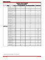
Battery Cable Size For Outboard Models
IMPORTANT: Only use copper battery cables. Do not use aluminum cables for any
outboard marine installations.
• If longer battery cables are required, the wire gauge size must increase. See chart
following for correct wire gauge size.
• DTS L models are equipped with 3.7 m (12 ft.) cables. DTS XL and XXL models are
not shipped with battery cables.
a
b
a - Wire gauge size
90-10234050
or70
b - Battery cable length
Page 21 / 42
200/225 OPTIMAX DTS
Copper Battery Cable Wire Gauge Size
Wire Gauge Size Number SAE
Models
Cable Length
6-25 hp
30-115 hp (except OptiMax)
125-250 hp (except OptiMax)
OptiMax/Verado
2.4 m (8 ft.)
81.
61.
-
-
2.7 m (9 ft.)
6
4
-
-
3.0 m (10 ft.)
6
4
61.
-
3.4 m (11 ft.)
6
4
4
-
3.7 m (12 ft.)
6
4
4
41.
4.0 m (13 ft.)
6
2
4
2
4.3 m (14 ft.)
4
2
4
2
4.6 m (15 ft.)
4
2
4
2
4.9 m (16 ft.)
4
2
2
2
5.2 m (17 ft.)
4
2
2
2
5.5 m (18 ft.)
4
2
2
2
5.8 m (19 ft.)
4
2
2
2
6.1 m (20 ft)
4
2
2
2
6.4 m (21 ft.)
2
1
2
1
6.7 m (22 ft.)
2
1
2
1
7.0 m (23 ft.)
2
1
2
1
7.3 m (24 ft.)
2
1
2
1
7.6 m (25 ft.)
2
1
2
1
7.9 m (26 ft.)
2
1/0
1
1/0
8.2 m (27 ft.)
2
1/0
1
1/0
8.5 m (28 ft.)
2
1/0
1
1/0
8.8 m (29 ft.)
2
1/0
1
1/0
9.1 m (30 ft.)
2
1/0
1
1/0
9.4 m (31 ft.)
2
1/0
1
1/0
9.8 m (32 ft.)
2
1/0
1
1/0
10.1 m (33 ft.)
2
2/0
1/0
2/0
10.4 m (34 ft.)
2
2/0
1/0
2/0
10.7 m (35 ft.)
1
2/0
1/0
2/0
11.0 m (36 ft.)
1
2/0
1/0
2/0
11.3 m (37 ft.)
1
2/0
1/0
2/0
11.6 m (38 ft.)
1
2/0
1/0
2/0
11.9 m (39 ft.)
1
2/0
1/0
2/0
12.2 m (40 ft.)
1
2/0
1/0
2/0
1. Standard (original) cable length and wire gauge size.
Page 22 / 42
90-10234050
200/225 OPTIMAX DTS
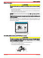
Battery Information
! CAUTION
Hex nuts must be used to secure battery leads to battery posts to avoid loss of electrical
power.
•
•
Do not use deep cycle batteries. Engines must use a marine starting battery with 1000
MCA, 800 CCA or 180 Ah.
When connecting engine battery, hex nuts must be used to secure battery leads to
battery posts. Torque nuts to specification.
Description
Nm
lb. in.
Hex nuts
13.5
120
lb. ft.
IMPORTANT: Battery cable size and length is critical. Refer to engine installation manual
for size requirements.
Decal needs to be placed on or near battery box for future service reference. One
5/16 in. and one 3/8 in. hex nut are supplied per battery for wing nut replacement. Metric
hex nuts are not supplied.
NOTICE - DTS & Optimax Engines
DO NOT USE DEEP CYCLE BATTERIES!
DTS (Digital Throttle and Shift) applications and
Optimax engines must use a marine starting
battery with 1000 MCA, 800 CCA, or 180 Ah.
rating.
13.5Nm (120 lbs. in.)
DO NOT
USE WING
NUTS.
IMPORTANT:
Battery cable size and length is critical. Refer to
engine installation manual for size requirements.
37-895387
Place decal on or near battery box for future service
reference. 5/16" and 3/8" hex nuts supplied for
wing nut replacement. Metric hex nuts not supplied.
3486
Connecting Battery Cables and DTS Power Harness
! CAUTION
To avoid the possibility of loss of electrical power due to the DTS power harness
connection being pulled off battery, fasten the DTS power harness to one of the battery
cables near the battery with cable tie.
•
•
•
Install DTS power harness directly to the starting battery only.
Do not extend lead length of harness.
See accessory manual for optional lead connection kit.
3711
90-10234050
Page 23 / 42
200/225 OPTIMAX DTS
SINGLE ENGINE - BATTERY AT STERN
a
c
b
d
3679
a - Battery
b - Black sleeve (negative)
c - Red sleeve (positive)
d - DTS power harness (provided)
SINGLE ENGINE - BATTERY AT HELM
b
d
c
e
f
a
h
g
3699
abcd-
Page 24 / 42
14 pin data harness
DTS command module harness
Junction box
DTS power harness (optional)
efgh-
Red sleeve (Positive)
Black sleeve (Negative)
Vessel sensor harness
Weather caps
90-10234050
200/225 OPTIMAX DTS
DUAL ENGINE - BATTERY AT STERN
g
e
c
c
f
a
b
d
a
b
d
3680
abcd-
90-10234050
Red sleeve (positive)
Black sleeve (negative)
Battery
DTS power harness (provided)
e - Ground cable
f - Data cable
g - Vessel sensor harness
Page 25 / 42
200/225 OPTIMAX DTS
DUAL ENGINE - BATTERY AT HELM
d
b
a
c
c
b
a
e
g
f
f
h
3701
abcd-
Black sleeve (negative)
Red sleeve (positive)
DTS power harness (optional)
DTS command module harness
efgh-
Junction box weather caps
14 pin data harness
Ground cable
Vessel sensor harness
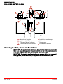
Connecting Fuel Tank, Oil Tank and Speed Sensor
IMPORTANT: Do not connect the blk/orn wire, if equipped, to the fuel tank sensor when
there is an engine battery ground strap connected to the fuel tank or sender assembly.
If not used, plug the unused open bullet connector with rubber plug.
IMPORTANT: If fuel tank is plastic and fuel sensor mounting plate is not connected to
battery ground, connect blk/orn wire, if equipped, to fuel sender mounting plate.
Page 26 / 42
90-10234050
200/225 OPTIMAX DTS
IMPORTANT: Metal fuel tanks must be grounded to hull or battery ground in accordance
to coast guard regulations.
c
a
b
PUR/YEL
BLK/ORN
BLK
GRY/BLU
YEL
BLU
TAN/ORN
WHT
BLK/ORN
LT.BLU/BLK
PNK/BLK
BLK/ORN
e
d
3714
a - Fuel tank
b - Oil tank
c - Oil tank sender
90-10234050
d - Harness
e - Black/orange wire to fuel tank
sensor, if equipped
Page 27 / 42
200/225 OPTIMAX DTS
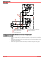
Switched 12V Accessory Connection
e
c
d
PUR
RED
f
b
g
h
+
ob01495
-
a
abcd-
Page 28 / 42
Battery
Fuse - 40 Amp
Power harness with 40 Amp fuse
Switched 12V
efgh-
Complete kit
Terminal block
Accessory power relay
DTS Command Module harness
90-10234050
200/225 OPTIMAX DTS
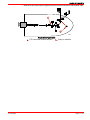
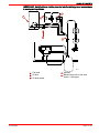
DTS Wiring - Single Engine
PANEL CONTROL
a
b
OFF O
N
BLK
BLK/YEL
BLK
BLK/YEL
c
WHITE
BLUE
e
+
BLK/ORG
PUR/YEL
GRN/YEL
GRN/ORG
GRN/RED
-
d
f
g
j
i
h
3718
abcde-
90-10234050
Start/stop switch (optional)
SmartCraft System View (optional)
SmartCraft Link Gauge (optional)
GPS connection
Displace harness
fghij-
Cable adaptor (male to female)
Weather caps
Junction box (optional)
Accessory power relay (optional)
Foot throttle (optional)
Page 29 / 42
200/225 OPTIMAX DTS
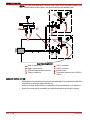
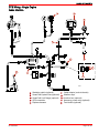
CONSOLE CONTROL
a
b
OFF O
BLK
c
BLK/YEL
BLK
BLK/YEL
N
WHITE
BLUE
e
-
+
BLK/ORG
PUR/YEL
GRN/YEL
GRN/ORG
GRN/RED
d
f
g
j
i
h
3717
abcde-
Page 30 / 42
Start/stop switch (optional)
SmartCraft System View (optional)
SmartCraft Link Gauge (optional)
GPS connection
Display harness
fghij-
Cable adaptor (male to female)
Weather caps
Junction box
Accessory power relay (optional)
Foot throttle (optional)
90-10234050
200/225 OPTIMAX DTS
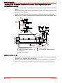
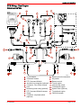
DTS Wiring - Dual Engine
CONSOLE CONTROL
n
q
p
m
o
l
l
k
j
j
i
i
h
+ –
d
d
g
g
e
e
c
f
f
i
a
c
s
b
b
r
3309
abcdefghij-
90-10234050
To port engine
Terminator resistor
DTS Command Module
Junction box connection (optional)
Connector - Zero Effort controls
Horn
Accessory power relay (optional)
DTS Command Module harness
Clamp
Connector - stop/start switch
(optional)
k - Remote control connections
l - Key switch
m -Remote control
n - To port engine
o - Lanyard stop switch
p - To starboard engine
q - System View (optional)
r - To starboard engine
s - CAN link harness
Page 31 / 42
200/225 OPTIMAX DTS
System Wiring Installation Checklist
DATA CABLE
Verify the data harness is not routed near sharp edges, hot surfaces or moving parts.
Verify data harness is not routed near ignition components (coils, spark plug leads,
and spark plugs), high power VHF coax or radios.
JUNCTION BOX (IF EQUIPPED)
Verify the data harness is not routed near sharp edges, hot surfaces or moving parts.
Ensure the harness connections are fastened within 25.4 cm (10 in.) of the junction
box.
Verify that all unused receptacles are covered with a weather cap.
NON-MERCURY MARINE SUPPLIED IGNITION KEY SWITCH
If a non-Mercury Marine ignition key is used, verify that it passes the ingress protection
testing per IEC IP66 specification minimum. Ignition switches must pass this
specification.
ELECTRONIC REMOTE CONTROL
Ensure Electronic Remote Control (ERC) connections are completed following ERC
installation instructions prior to engine operation.
DTS COMMAND MODULE HARNESS
Verify that all connectors are properly inserted and locked in their receptacle (remote
control, key switch, command module, lanyard stop switch and junction box, if
equipped).
Verify that while moving the remote control handle (full forward and full reverse) the
harness has unobstructed movement (moves freely).
Verify that the lanyard stop switch is wired into the system correctly.
Verify that the harness is fastened along the routing path.
Verify that all unused connectors have weather caps to prevent corrosion.
BATTERY
Verify that wing nuts have been replaced with hex nuts, provided.
Verify that all engine battery cables are connected to the correct terminals.
Verify that the DTS power harness leads are connected to the starting battery and
secured with locknuts.
Ensure the 5 Amp fuse for the DTS power harness is accessible.
LANYARD STOP SWITCH
Verify that the switch is installed.
Verify that the switch is connected to the DTS command module harness.
Fuel Hose and Oil Hose Connections
Fuel Hose Connection
Fuel Hose Size - Minimum fuel line inside diameter (I.D.) is 8mm (5/16 in.), with separate
fuel line/fuel tank pickup for each engine.
1. Fasten remote fuel hose to fitting with hose clamp.
Page 32 / 42
90-10234050
200/225 OPTIMAX DTS
2. Connect the remote oil hoses to the engine hose connections. Fasten hose
connections with cable ties.
b
d
c
e
a
3767
a - Hose clamp
b - Cable tie
c - Oil hose without blue stripe
d - Oil hose with blue stripe
e - Remote fuel hose
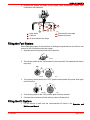
Filling the Fuel System
When starting an engine for the first time, or starting an engine that ran out of fuel or was
drained of fuel, fill and prime the fuel system.
1. Squeeze the fuel line primer bulb until it feels firm.
ob00349
2. Turn the key switch to the "ON" position for three seconds. This operates the electric
fuel pump.
ACC ON
ART
ST
F
OF
ART
ST
F ACC ON
OF
ob00364
3484
3. Turn the key switch back to the "OFF" position and squeeze the primer bulb again
until it feels firm.
ACC ON
ART
ST
F ACC ON
OF
ob00360
ART
ST
F
OF
3482
4. Turn the key switch to the "ON" position again for three seconds.
5. Continue this procedure until the fuel line primer bulb stays firm.
Filling the Oil System
1. Fill the remote oil tank with the recommended oil listed in the Operation and
Maintenance Manual.
90-10234050
Page 33 / 42
200/225 OPTIMAX DTS
2. Tighten the fill cap.
a
or111
a - Fill cap
3. Remove the cap and fill the engine oil tank with oil.
a
b
3763
a - Fill cap
b - Engine oil tank
4. Reinstall the fill cap.
Priming Oil Injection Pump
IMPORTANT: DTS helm configuration must be completed before performing the
following procedure.
Before starting the engine for the first time, prime the oil injection pump. Priming will
remove any air that may be in the pump, oil supply hose or internal passages.
b
a
3768
a - Oil supply hose
Page 34 / 42
b - Oil injection pump
90-10234050
200/225 OPTIMAX DTS
! CAUTION
Avoid fuel pump damage. Always fill the engine fuel system with fuel before priming the
oil injection pump. Otherwise, the fuel pump will run without fuel during the priming
process.
1. Fill the fuel system.
a. Connect fuel hose.
b. Fill the fuel system by squeezing the primer bulb.
c. Squeeze the fuel line primer bulb until it feels firm.
ob00349
d.
Turn the ignition key switch to the "ON" position for three seconds. This operates
the electric fuel pump.
ACC ON
ART
ST
F
OF
ART
ST
F ACC ON
OF
ob00364
3484
e.
Turn the ignition key switch back to the "OFF" position, and squeeze the primer
bulb again until it feels firm.
f.
Turn the ignition key switch to the "ON" position again for three seconds.
g. Continue this procedure until the fuel primer bulb stays firm.
2. Turn the ignition key switch to the "ON" position.
ACC ON
ART
ST
F ACC ON
OF
ART
ST
F
OF
ob00364
3484
3. Within the first 10 seconds after the key switch has been turned on, move the remote
control handle from neutral (N) into forward (F). This will automatically start the
priming process.
N
F
N
R F
R
3413
3417
90-10234050
Page 35 / 42
200/225 OPTIMAX DTS
Purging Air From the Engine Oil Tank
IMPORTANT: DTS helm configuration must be completed before performing the
following procedure.
1. Loosen the fill cap on the engine oil tank.
2. Start the engine.
3. Operate the engine until all the air has vented out and oil starts to flow out of the tank.
4. Re-tighten fill cap.
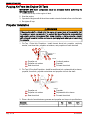
Propeller Installation
! WARNING
If the propeller shaft is rotated while the engine is in gear, there is the possibility that
the engine will crank over and start. To prevent this type of accidental engine starting
and possible serious injury caused from being struck by a rotating propeller, always
shift outboard to neutral position and remove spark plug leads when you are servicing
the propeller.
1. Flo-Torq I Drive Hub Propellers - Install forward thrust hub, propeller, continuity
washer, rear thrust hub, propeller nut retainer, and propeller nut onto the shaft.
b
a
c
d
e
f
ob00382
a - Propeller nut
b - Propeller nut retainer
c - Rear thrust hub
d - Continuity washer
e - Propeller
f - Forward thrust hub
2. Flo-Torq II Drive Hub Propellers - Install forward thrust hub, replaceable drive sleeve,
propeller, thrust hub, propeller nut retainer and propeller nut onto the shaft.
a
b
e
c
d
a - Propeller nut
b - Propeller nut retainer
c - Rear thrust hub
f
ob00421
d - Propeller
e - Replaceable drive sleeve
f - Forward thrust hub
3. Place a block of wood between gearcase and propeller and torque to specifications.
Page 36 / 42
Description
Nm
Propeller nut
75
lb. in.
lb. ft.
55
90-10234050
200/225 OPTIMAX DTS
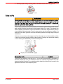
4. Secure propeller nut by bending three of the tabs into the thrust hub grooves.
ob00422
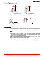
Trim In Pin
! WARNING
Avoid possible serious injury or death. Adjust outboard to an intermediate trim position
as soon as boat is on plane to avoid possible ejection due to boat spin out. Do not
attempt to turn boat when on plane if outboard is trimmed extremely in or down and
there is a pull on the steering wheel.
Some boats, particularly some bass boats, are built with a greater than normal transom
angle, which will allow the outboard to be trimmed further in or under. This greater trim
under capability is desirable to improve acceleration, reduce the angle and time spent in
a bow high boat during planing off, and in some cases, may be necessary to plane off a
boat with aft live wells, given the variety of available propellers and height range of engine
installations.
However, once on plane, the engine should be trimmed to a more intermediate position
to avoid a bow-down planing condition called plowing. Plowing can cause bow steering
or over steering and inefficiently consumes horsepower.
a
or116
a - Tilt pin (not included with engine)
Stainless Steel Tilt Pin
17-49930A1
The owner may decide to limit the trim in. This can be accomplished by purchasing a
stainless steel tilt pin from your dealer and insert it in whatever adjustment hole in the
transom brackets is desired. A non-stainless steel shipping bolt should not be used in this
application other than on a temporary basis.
90-10234050
Page 37 / 42
200/225 OPTIMAX DTS
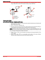
Paddle Wheel Speed Sensor Installation (If Equipped)
Parts Provided
d
a
i
e
i
c
b
ABCD
h
f
abcde-
g
Spare pin yoke
Wire retainer
Connector
Bracket
Paddle wheel
j
fghij-
ob01505
Flat washer (2)
#10 - 19 mm (3/4 in.) screw (4)
Cable cap
#6 - 12 mm (1/2 in.) screw (4)
Clamp (2)
Selecting Location
Single engine installation - Mount paddle wheel on the transom where the propeller blade
is rotating downward. Usually the right (starboard) side to minimize cavitation. If feasible,
mount at least 50 mm (2 in.) beyond the swing radius of the propeller.
Dual engine installation - Mount the paddle wheel between the engines as close to the
center line (keel) of the boat as possible. On slower, heavier displacement boats,
however, positioning it farther from the keel is acceptable.
NOTE: Do not mount the paddle wheel directly behind any stakes, ribs, intakes or outlets
for live wells or any protrusion that may cause turbulence or cavitation.
a
ob01506
a - 50 mm (2 in.)
Page 38 / 42
90-10234050
200/225 OPTIMAX DTS
Transom Angle Requirements
Standard 13° to 20° transoms - No special adjustment required.
a
b
ob01507
a - 13° transom angle
b - 20° transom angle
Stepped or undercut transom with 3 angles - A small shim of tapered plastic, metal or
wood must be fabricated and installed as shown. Mount the paddle wheel on the step for
best performance.
a
ob01508
a - Shim
Installing Bracket
1. Cut out the template. At the location selected, tape the template to the transom. Make
sure the black dotted line on the template is aligned with the transom bottom edge,
as shown.
NOTE: The mounting template provided is located on the last page of this instruction
sheet.
2. Using a #28 or 9/64 in. bit, drill two 22 mm (7/8 in.) deep holes where indicated on
the template. To prevent drilling too deeply, wrap masking tape around the drill bit
22 mm (7/8 in.) from the point end of drill bit.
NOTE: In fiberglass hulls, first chamfer the gelcoat using a 6 mm (1/4 in.) drill; drilling
about 15 mm (1/16 in.) deep to prevent surface cracks.
3. To prevent water seepage into the transom, apply a marine sealer (such as RTV) to
the two #10 screws provided. Using the washer provided, attach and tighten the
bracket to the hull making sure the bracket is flush with the underside of the hull.
90-10234050
Page 39 / 42
200/225 OPTIMAX DTS
4. Fill any gap between the housing and the transom with a caulking material, as shown.
Using a putty knife, smooth the surface to ensure proper water flow.
a
e
b
c
a - Template
b - 50 mm (2 in.)
c - #10 screw
d
ob01509
d - Flat washer (2)
e - Caulking
Routing the Cable
DRILLING HOLE THROUGH TRANSOM (OPTIONAL)
1. Select a transom location for the hole above the water line that does not interfere with
other cables and controls.
2. Drill a 15 mm (5/8 in.) diameter hole.
3. Route the cable through the drilled hole. Seal the transom hole with silicone (RTV) or
a comparable marine sealer after the cable has been routed through.
NOTE: The hole for the first clamp should be 25 mm (1 in.) above the paddle wheel. The
hole for the second clamp should be positioned halfway between the first clamp and the
cap covering the transom hole drilled for the cable.
4. Using a 2.8 mm (7/64 in.) bit, drill holes for the clamps and cap approximately 13 mm
(1/2 in.) deep.
5. Apply silicone sealer (RTV) or a comparable marine sealer to the screw threads,
install the cable clamps and feed the cable through cable cap.
Page 40 / 42
90-10234050
200/225 OPTIMAX DTS
WITHOUT DRILLING HOLE THROUGH TRANSOM (OPTIONAL)
Route the cable over the transom or through a drain hole that is above the water line.
a
b
e
c
d
abcde-
ob01510
Splash well drain hole
Cable cap
Cable clamp
Paddle wheel assembly
Distance between first cable clamp and top of paddle wheel - 25.4 mm
(1.0 in.)
Installing and Removing the Paddle Wheel
Installation - Slide the pins into the slots in the bracket and snap the tabs into place.
Removal - squeeze open (unlock) the tabs and pull on the paddle wheel.
a
b
ob01511
a - Tabs
b - Pins
Wiring Connections
IMPORTANT: Before making wire connections, make sure wires are routed through the
transom.
90-10234050
Page 41 / 42
200/225 OPTIMAX DTS
NOTE: Wires can only be pushed into the connector one way. Align the wire terminal with
the tabs inside the connector. Have the wiring routed through the transom. Push each
wire terminal into its respective location in the connector. Push wire in until they snap into
place. Secure wires into connector with the wire retainer.
DC BA
DC B A
WHT
YEL
BLU
BLK
b
a
b
a - Connector
ob01512
b - Wire retainer
Template - Paddle Wheel Speed Sensor
a
b
ob01513
a - Drill holes here
b - Align dotted line with the transom bottom edge and fold under
Page 42 / 42
90-10234050