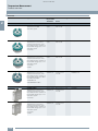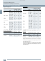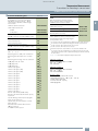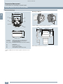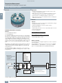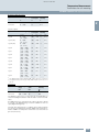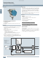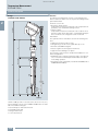
1
2 © Siemens AG 2015 Temperature Measurement 2/2 2/4 2/8 2/15 2/22 2/28 2/35 2/42 Product overview Transmitters for mounting in sensor head SITRANS TH100 two-wire system (Pt100) SITRANS TH200 two-wire system universal SITRANS TH300 two-wire system universal, HART SITRANS TH400 fieldbus transmitter Transmitters for rail mounting SITRANS TR200 two-wire system universal SITRANS TR300 two-wire system universal, HART SITRANS TW four wire system, universal, HART 2/54 2/59 2/68 Transmitters for field mounting SITRANS TF280 WirelessHART SITRANS TF two-wire system SITRANS TF fieldbus transmitter 2/59 Field indicator SITRANS TF Field indicator for 4 to 20 mA 2/75 2/77 2/79 2/80 2/82 2/82 2/90 2/94 2/96 SITRANS TS500 Technical Description - Types ST, SS, SR threaded process connection - Types FT, FS, FR flanged process connection - Types SWT, SWS, SWR socketwell process connection - Type GP general purpose no thermowell - Type GP Selection and Ordering Data Schematics Temperature transmitters for mounting in the connection head You can download all instructions, catalogs and certificates for SITRANS T free of charge at the following Internet address: www.usa.siemens.com/temperature Siemens FI 01 · 2015 US Edition © Siemens AG 2015 Temperature Measurement Product overview ■ Overview Application 2 Mounting of transmitter with Ex protection Page Software for parameterization Transmitter Sensor Zone 2 and zone 1 Zone 2, zone 1 and zone 0 2/4 SIPROM T SITRANS TH200 Zone 2 and zone 1 Transmitters for connection to resistance thermometers, resistance-based sensors, thermocouples and DC voltages up to 1.1 V • Two-wire system • Universal Zone 2, zone 1 and zone 0 2/8 SIPROM T SITRANS TH300 Zone 2 and zone 1 Transmitters for connection to resistance thermometers, resistance-based sensors, thermocouples and DC voltages up to 1.1 V • Two-wire system • Universal • HART Zone 2, zone 1 and zone 0 2/15 SIMATIC PDM Temperature transmitter for head mounting SITRANS TH100 Transmitters for Pt100 • Two-wire system SITRANS TH400 Zone 2, zone 1 Zone 2, zone 1, 2/22 and zone 21 zone 0, zone 21, Transmitters for connection to zone 20 resistance thermometers, resistance-based sensors, thermocouples and DC voltages up to 0.9 V • Fieldbus transmitters • PROFIBUS PA • FOUNDATION fieldbus SIMATIC PDM for TH 400 with PROFIBUS PA Temperature transmitters for rail mounting 2/2 SITRANS TR200 Zone 2, zone 1 Zone 2, zone 1, 2/28 and zone 21 zone 0, zone 21, Transmitters for connection to zone 20 resistance thermometers, resistance-based sensors, thermocouples and DC voltages up to 1.1 V • Two-wire system • Universal SIPROM T SITRANS TR300 Zone 2, zone 1 Zone 2, zone 1, 2/35 and zone 21 zone 0, zone 21, Transmitters for connection to zone 20 resistance thermometers, resistance-based sensors, thermocouples and DC voltages up to 1.1 V • Two-wire system • Universal • HART SIMATIC PDM Siemens FI 01 · 2015 US Edition © Siemens AG 2015 Temperature Measurement Product overview Application Mounting of transmitter with Ex protection Transmitter SITRANS TW Safe area Transmitters for connection to resistance thermometers, resistance-based sensors, thermocouples, DC voltages and DC currents for: • Four-wire system Page Software for parameterization Sensor Zone 1, zone 0, 2/42 zone 21, zone 20 SIMATIC PDM SITRANS TF280 Transmitter for connection to resistance-based sensor • In field enclosure for heavy industrial use • battery-operated • WirelessHART - 2/54 Local operation via buttons SIMATIC PDM local with HART modem and wireless via WirelessHART SITRANS TF Zone 2 and zone 1 Transmitters for connection to resistance thermometers, resistance-based sensors, thermocouples and DC voltages up to 1.1 V • In field enclosure for heavy industrial use • HART, Universal Zone 2, zone 1 and zone 0 2/59 depending on the installed TH200/TH300 transmitter SITRANS TF Zone 2 and Fieldbus transmitters for connec- zone 1 tion to resistance thermometers, resistance-based sensors, thermocouples and DC voltages up to 0.8 V • In field enclosure for heavy industrial use • PROFIBUS PA • FOUNDATION fieldbus Zone 2, zone 1 and zone 0 2/68 SIMATIC PDM for PROFIBUS PA - 2/59 -- 2 Temperature transmitters for field mounting Field indicator for 4 to 20 mA signals SITRANS TF Field indicator for 4 to 20 mA signals Display of units can be userdefined Zone 2 and zone 1 Type Description Page SITRANS TS500 Temperature Sensor Assemblies Include thermowell, sensor, head and transmitters • Integrated temperature assemblies • Include thermowell, sensor, head and transmitter in single model number. • Various options include configuration, calibration and certificates. 2/75 Temperature sensors Siemens FI 01 · 2015 US Edition 2/3 © Siemens AG 2015 Temperature Measurement Transmitters for mounting in sensor head SITRANS TH100 two-wire system (Pt100) ■ Overview ■ Application Used in conjunction with Pt100 resistance thermometers, the SITRANS TH100 transmitters are ideal for measuring temperatures in all industries. Due to its compact size it can be installed in the connection head type B (DIN 43729) or larger. 2 The output signal is a direct current from 4 to 20 mA that is proportional to the temperature. Parameterization is implemented over the PC using the parameterization software SIPROM T and the modem for SITRANS TH100/TH200. If you already have a "modem for SITRANS TK" (Article No. 7NG3190-6KB), you can continue using this to parameterize the SITRANS TH100. Transmitters of the "intrinsically-safe" type of protection can be installed within potentially explosive atmospheres. The devices comply with the Directive 94/9/EC (ATEX), as well as FM and CSA regulations. ■ Function The SITRANS TH100 dispenses with electrical isolation and universal sensor connection to provide a low-cost alternative for Pt100 measurements. Mode of operation Its extremely compact design makes the SITRANS TH100 ideal for the retrofitting of measuring points or for the use of analog transmitters. The measured signal supplied by a Pt100 resistance thermometer (2, 3 or 4-wire system) is amplified in the input stage. The voltage, which is proportional to the input variable, is then converted into digital signals by a multiplexer in an analog/digital converter. They are converted in the microcontroller in accordance with the sensor characteristics and further parameters (measuring range, damping, ambient temperature etc.). The transmitter is available as a non-Ex version as well as for use in potentially explosive atmospheres. The signal prepared in this way is converted in a digital/analog converter into a load-independent direct current of 4 to 20 mA. For the parameterization, the SIPROM T software is used in combination with the modem for SITRANS TH100/TH200. An EMC filter protects the input and output circuits against electromagnetic interferences. ■ Benefits • Two-wire transmitter • Assembly in connection head type B (DIN 43729) or larger, or on a standard DIN rail • Can be programmed, which means that the sensor connection, measuring range, etc. can also be programmed • Intrinsically-safe version for use in potentially explosive areas Input Pt100 EMC_1 IC MUX A/D Uref Ic 6 A/D 5 Pt100 4 Output D/A U/I EMC_1 MUX μC 3 EMC_2 Uaux Iout D/A Resistance thermometer Input level with protective components Constant current source Multiplexer Analog-digital converter Digital-analog converter Voltage transformers, current transformers, constant voltage and reference voltage source Output level with protective components Auxiliary power supply Output current Microcontroller μC Linearization functions and storage of all data Uref + U I EMC_2 Uaux, Iout 4 ... 20 mA - SITRANS TH100, function diagram 2/4 Siemens FI 01 · 2015 US Edition © Siemens AG 2015 Temperature Measurement Transmitters for mounting in sensor head SITRANS TH100 two-wire system (Pt100) ■ Technical specifications Input Resistance thermometer Certificates and approvals Explosion protection ATEX EC type test certificate • "Intrinsic gas safety" type of protection Measured variable Temperature Sensor type PT100 to IEC 60751 Characteristic curve Temperature-linear Type of connection 2-, 3- or 4-wire circuit Resolution 14 bit Measuring accuracy • Span <250 °C (450 °F) • Span >250 °C (450 °F) < 0.25 °C (0.45 °F) < 0.1 % of span Repeatability < 0.1 °C (0.18 °F) Measuring current approx. 0.4 mA Measuring cycle < 0.7 s Measuring range -200 ... +850 °C -328 ... +1562 °F) Measuring span 25 ... 1050 °C (77 ... 1922 °F) Unit °C or °F Other certificates Offset programmable: -100 ... +100 °C (-180 ... +180 °F) Line resistance Max. 20 (total from feeder and return conductor) Software requirements for SIPROM T PC operating system Noise rejection 50 and 60 Hz • "Non-sparking" type of protection • "Intrinsic dust safety" type of protection Explosion protection FM for USA and Canada (cFMUS) • FM approval • Degree of protection PTB 05 ATEX 2049X II 1 G Ex ia IIC T6/T4 II (1) 2 G Ex ib [ia Ga] IIC T6/T4 Gb II (1) 3 G Ex ic [ia Ga] IIC T6/T4 Gc II 3 G Ex ic IIC T6/T4 Gc II 3 G Ex nA IIC T6/T4 Gc II 3 G Ex nA[ic] IIC T6/T4 Gc II 1 D Ex ia IIIC T115 °C Da PID 3024169 IS Cl I, II, III, Div 1, GP ABCDEFG T4/T5/T6 Cl I, ZN 0,1 AEx ia IIC T4/T5/T6 NI Cl I, II, III, Div 2, GP ABCDFG T4/T5/T6 Cl I, ZN 2, NI IIC T4/T5/T6 GOST, NEPSI, PESO Windows ME, 2000, XP, Win 7 and Win 8; can also be used in connection with RS 232 modem under Windows 95, 98 and 98SE Output Output signal 4 ... 20 mA, two-wire Auxiliary power 8.5 ... 36 V DC (30 V for Ex ia and ib; 32 V for Ex nL/ic; 35 V for Ex nA) Max. load (Uaux - 8.5 V)/0.023 A Overrange 3.6 ... 23 mA, infinitely adjustable (default range: 3.84 ... 20.5 mA) Error signal (following sensor fault) (conforming to NE43) 3.6 ... 23 mA, infinitely adjustable (default range: 3.6 mA or 22.8 mA) Damping time 0 ... 30 s (default value: 0 s) Protection Against reversed polarity Resolution 12 bit Accuracy at 23 °C (73.4 °F) < 0.1 % of span Temperature effect < 0.1 %/10 °C (0.1 %/18 °F) Effect of auxiliary power < 0.01 % of span/V Effect of load impedance < 0.025 % of max. span/100 Long-term drift • < 0.025 % of the max. span in the first month • < 0.035 % of the max. span after one year • < 0.05 % of the max. span after 5 years Ambient conditions Ambient temperature range -40 ... +85 °C (-40 ... +185 °F) Storage temperature range -40 ... +85 °C (-40 ... +185 °F) Relative humidity 98 %, with condensation Electromagnetic compatibility According to EN 61326 and NAMUR NE21 Construction Weight 50 g Dimensions See dimensional drawing Material Molded plastic Cross-section of cables Max. 2.5 mm2 (AWG 13) Degree of protection to IEC 60529 • Enclosure IP40 • Terminals IP00 Siemens FI 01 · 2015 US Edition 2/5 2 © Siemens AG 2015 Temperature Measurement Transmitters for mounting in sensor head SITRANS TH100 two-wire system (Pt100) ■ Selection and Ordering data ■ Dimensional drawings • Without explosion protection 7NG3211-0NN00 • With explosion protection "Intrinsic safety" type of protection and for zone 2 - to ATEX - to FM (cFMUS) 7NG3211-0AN00 7NG3211-0BN00 Further designs Order code 20.8 (0.82) SITRANS TH100 temperature transmitters for Pt100 for installation in connection head, type B (DIN 43729), two-wire system, 4 ... 20 mA, programmable, without electrical isolation 44 (1.73) Internal diameter Center hole 6.3 (0.25) 4..20mA Add "-Z" to Article No. and specify Order code(s) Test report (5 measuring points) C11 1 + SIEMENS 1 Customer-specific programming Add "-Z" to Article No. and specify Order code(s) Measuring range to be set Specify in plain text (max. 5 digits): Y01: ... to ... °C, °F Y011) Measuring point no. (TAG), max. 8 characters Y172) Measuring point descriptor, max. 16 characters Y232) Pt100 (IEC) 2-wire, RL = 0 U023) Pt100 (IEC) 3-wire U033) Pt100 (IEC) 4-wire U043) Special differing customer-specific programming, specify in plain text Y094) Fail-safe value 3.6 mA (instead of 22,8 mA) U362) Accessories Article No. Modem for SITRANS TH100, TH200, TR200 and TF with TH200 incl. SIPROM T parameterization software With USB connection 7NG3092-8KU MiniDVD for temperature measuring instruments With documentation in German, English, French, Spanish, Italian, Portuguese and SIPROM T parameterization software A5E00364512 DIN rail adapters for head transmitters (Quantity delivered: 5 units) 7NG3092-8KA Connecting cable 4-wire, 150 mm, for sensor connections when using head transmitters in the high hinged cover (set with 5 units) 7NG3092-8KC 3 6 4 For customer-specific programming for RTD and TC, the start value and the end value of the required measuring span must be specified here. For this selection, Y01 or Y09 must also be selected. 3) For this selection, Y01 must also be selected. 4) For customer-specific programming, for example mV and ohm, the start value and the end value of the required measuring span and the unit must be entered here. Mounting screw M4x25 6 5 4 1) 2 – 2 3 3-W 5 33 (1.3) 1(+) and 2(-) 3, 4, 5 and 6 Auxiliary power supply Uaux, output current IOut Pt100 sensor (for connection, see sensor connection assignment) SITRANS TH100, dimensions in mm (inch) Mounting on DIN rail SITRANS TH100, mounting of transmitter on DIN rail 14 (0.55) 50.5 (1.99) 33 (1.30) 2) 59.6 (2.35) 2 Article No. Supply units see Chapter "Supplementary Components". Ordering example 7NG3211-0NN00-Z Y01+Y23+U03 Y01: -10 ... +100 °C Y23: TICA1234HEAT Factory setting: • Pt100 (IEC 751) with 3-wire circuit • Measuring range: 0 … 100 °C (32 … 212 °C) • Error signal in the event of sensor breakage: 22.8 mA • Sensor offset: 0 C (0 °F) • Damping 0.0 s 2/6 Siemens FI 01 · 2015 US Edition DIN rail adaptor, dimensions in mm (inch) © Siemens AG 2015 Temperature Measurement Transmitters for mounting in sensor head SITRANS TH100 two-wire system (Pt100) ■ Schematics 6 5 4 3 3 5 6 4 3-W 6 4 3-W 3 3 4 Pt100 Two-wire system (parameterizable line resistance) Three-wire system Uaux + 6 4 3-W 3 - 6 5 4 2 5 Pt100 3 6 5 4..20mA 5 1 + SIEMENS 1 – Pt100 6 5 Four-wire system 2 2 6 Connection of auxiliary power supply (Uaux) power supply (Uaux) SITRANS TH100, sensor connection assignment Siemens FI 01 · 2015 US Edition 2/7 © Siemens AG 2015 Temperature Measurement Transmitters for mounting in sensor head SITRANS TH200 two-wire system, universal ■ Overview ■ Application SITRANS TH200 transmitters can be used in all industrial sectors. Due to their compact size they can be installed in the connection head type B (DIN 43729) or larger. The following sensors/signal sources can be connected over their universal input module: • Resistance thermometers (2, 3 or 4-wire system) • Thermocouples • Resistance-based sensors and DC voltage sources 2 The output signal is a direct current from 4 to 20 mA in accordance with the sensor characteristic. Transmitters of the "intrinsically safe" type of protection can be installed within potentially explosive atmospheres. The devices comply with the Directive 94/9/EC (ATEX), as well as FM and CSA regulations. ■ Function Ultra flexible - with the universal SITRANS TH200 transmitter • Two-wire devices for 4 to 20 mA • Mounting in the connection head of the temperature sensor • Universal input for virtually any type of temperature sensor • Configurable over PC ■ Benefits • Compact design • Flexible mounting and center hole allow you to select your preferred type of installation • Electrically isolated • Test sockets for multimeters • Diagnostics LED (green/red) • Sensor monitoring open circuits and short-circuits • Self-monitoring • Configuration status stored in EEPROM • SIL2 (with Order Code C20), SIL2/3 (with C23) • Expanded diagnostic functions, such as slave pointer, operating hours counter, etc. • Special characteristic • Electromagnetic compatibility to EN 61326 and NE21 The SITRANS TH200 is configured over a PC. A USB or RS 232 modem is linked to the output terminals for this purpose. The configuration data can now be edited using the SIPROM T software tool. The configuration data are then permanently stored in the non-volatile memory (EEPROM). Once the sensors and power supply have been correctly connected, the transmitter outputs a temperature-linear output signal and the diagnostics LED displays a green light. In the case of a sensor short-circuit, the LED flashes red, an internal device fault is indicated by a steady red light. The test socket can be used to connect an ammeter at any time for monitoring purposes and plausibility checks. The output current can be read without any interruption, or even without opening the current loop. SITRANS TH200/TH300 (2) Test TC/RTD sensor +1 A D Input A/D Sensors μC1 Analog-digital converter Resistance thermometer, thermocouple, resistance-based sensor, mV sensor Microcontroller, secondary circuit SITRANS TH200 function diagram 2/8 Siemens FI 01 · 2015 US Edition μC2 μC1 (1) D A 4 ... 20 mA Uaux, Iout -2 Output μC2 D/A Uaux Iout Microcontroller, primary circuit Digital-analog converter Auxiliary power supply Output current (1) Electrically isolated (2) LED © Siemens AG 2015 Temperature Measurement Transmitters for mounting in sensor head SITRANS TH200 two-wire system, universal ■ Technical specifications Input Response time 250 ms for 1 sensor with opencircuit monitoring Open-circuit monitoring Always active (cannot be disabled) Short-circuit monitoring can be switched on/off (default value: OFF) Measuring range parameterizable max. 0 ... 2200 (see table "Digital measuring errors") Resistance thermometer Measured variable Temperature Sensor type • to IEC 60751 Pt25 … Pt1000 • To JIS C 1604; a = 0.00392 K-1 Pt25 … Pt1000 • to IEC 60751 Ni25 … Ni1000 • Special type over special characteristic (max. 30 points) Min. measured span 5 ... 25 (see Table "Digital measuring errors") Sensor factor 0.25 ... 10 (adaptation of the basic type, e.g. Pt100 to version Pt25 ... 1000) Characteristic curve Resistance-linear or special characteristic Units °C or °F Connection • Standard connection 1 resistance thermometer (RTD) in 2-wire, 3-wire or 4-wire system • Generation of average value 2 identical resistance thermometers in 2-wire system for generation of average temperature • Generation of difference 2 identical resistance thermometers (RTD) in 2-wire system (RTD 1 – RTD 2 or RTD 2 – RTD 1) Interface Thermocouples Measured variable • Type B • Type C • Type D Pt30Rh-Pt6Rh to DIN IEC 584 W5 %-Re acc. to ASTM 988 W3 %-Re acc. to ASTM 988 • Type E • Type J • Type K NiCr-CuNi to DIN IEC 584 Fe-CuNi to DIN IEC 584 NiCr-Ni to DIN IEC 584 • Type L • Type N • Type R Fe-CuNi to DIN 43710 NiCrSi-NiSi to DIN IEC 584 Pt13Rh-Pt to DIN IEC 584 Pt10Rh-Pt to DIN IEC 584 Cu-CuNi to DIN IEC 584 Cu-CuNi to DIN 43710 °C or °F • Two-wire system Parameterizable line resistance 100 (loop resistance) • Three-wire system No balancing required • Four-wire system No balancing required • Type S • Type T • Type U Sensor current 0.45 mA Units Response time 250 ms for 1 sensor with opencircuit monitoring Connection Open-circuit monitoring Always active (cannot be disabled) Short-circuit monitoring can be switched on/off (default value: ON) Measuring range parameterizable (see table "Digital measuring errors") Min. measured span 10 °C (18 °F) Characteristic curve Temperature-linear or special characteristic Temperature Sensor type (thermocouples) • Standard connection 1 thermocouple (TC) • Generation of average value 2 thermocouples (TC) • Generation of difference 2 thermocouples (TC) (TC1 – TC2 or TC2 – TC1) Response time 250 ms for 1 sensor with opencircuit monitoring Open-circuit monitoring Can be switched off Cold junction compensation • Internal With integrated Pt100 resistance thermometer • External With external Pt100 IEC 60571 (2-wire or 3-wire connection) Resistance-based sensors Measured variable Actual resistance Sensor type Resistance-based, potentiometers • External fixed Cold junction temperature can be set as fixed value Units Measuring range Parameterizable (see table "Digital measuring errors") Min. measured span Min. 40 ... 100 °C (72 ... 180 °F) (see table "Digital measuring errors") Temperature-linear or special characteristic Connection • Normal connection 1 resistance-based sensor (R) in 2-wire, 3-wire or 4-wire system • Generation of average value 2 resistance-based sensors in 2-wire system for generation of average value Characteristic curve • Generation of difference 2 resistance thermometers in 2-wire system (R1 – R2 or R2 – R1) Measured variable DC voltage Sensor type DC voltage source (DC voltage source possible over an externally connected resistor) Interface mV sensor • Two-wire system Parameterizable line resistance 100 (loop resistance) Units mV • Three-wire system No balancing required Response time • Four-wire system No balancing required 250 ms for 1 sensor with opencircuit monitoring Sensor current 0.45 mA Open-circuit monitoring Can be switched off Measuring range -10 ... +70 mV-100 … +1100 mV Siemens FI 01 · 2015 US Edition 2/9 2 © Siemens AG 2015 Temperature Measurement Transmitters for mounting in sensor head SITRANS TH200 two-wire system, universal 2 Min. measured span 2 mV or 20 mV Certificates and approvals Overload capability of the input -1.5 ... +3.5 V DC Explosion protection ATEX Input resistance 1 M EC type test certificate PTB 05 ATEX 2040X Characteristic curve Voltage-linear or special characteristic • "Intrinsic safety" type of protection II 1 G Ex ia IIC T6/T4 II 2 (1) G Ex ia/ib IIC T6/T4 II 3(1) G Ex ia/ic IIC T6/T4 II 1D Ex iaD 20 T115 °C Output signal 4 ... 20 mA, 2-wire Auxiliary power 11 ... 35 V DC ((to 30 V for Ex ia and ib; to 32 V for Ex nA / nL / ic) • "Operating equipment that is nonignitable and has limited energy" type of protection II 3 G Ex nL IIC T6/T4 II 3 G Ex nA IIC T6/T4 Max. load (Uaux – 11 V)/0.023 A Explosion protection: FM for USA Overrange 3.6 ... 23 mA, infinitely adjustable (default range: 3.80 mA ... 20.5 mA) • FM approval FM 3024169 • Degree of protection IS / Cl I, II, III / Div 1 / GP ABCDEFG T6, T5, T4 Cl I / ZN 0 / AEx ia IIC T6, T5, T4 NI / Cl I / Div 2 / GP ABCDFG T6, T5, T4 NI / Cl I / ZN 2 / IIC T6, T5, T4 Output Error signal (e.g. following sensor fault) (conforming to NE43) 3.6 ... 23 mA, infinitely adjustable (default value: 22.8 mA) Sample cycle 0.25 s nominal Damping Software filter 1st order 0 ... 30 s (parameterizable) Explosion protection to FM for Canada (cFMUS) Protection Against reversed polarity • FM approval FM 3024169C Electrically isolated Input against output (1 kVeff) • Degree of protection IS / Cl I, II, III / Div 1/ GP ABCDEFG T6, T5, T4 NI / Cl I / DIV 2 / GP ABCD T6, T5, T4 NIFW / Cl I, II, III / DIV 2 / GP ABCDFG T6, T5, T4 DIP / Cl II, III / Div 2 / GP FG T6, T5, T4 Cl I / ZN 0 / Ex ia IIC T6, T5, T4 Cl I / ZN 2 / Ex nA nL IIC T6, T5, T4 Other certificates GOST, NEPSI, PESO, IEC, EXPOLABS Measuring accuracy Digital measuring errors See table "Digital measuring errors" Reference conditions • Auxiliary power 24 V 1 % • Load 500 • Ambient temperature 23 °C • Warming-up time > 5 min Error in the analog output (digital/analog converter) < 0.025 % of span Error due to internal cold junction < 0.5 °C (0.9 °F) Influence of ambient temperature • Analog measuring error 0.02 % of span/10°C (18 °F) • Digital measuring errors - with resistance thermometers 0.06 °C (0.11 °F)/10°C (18 °F) - with thermocouples 0.6 °C (1.1 °F)/10°C (18 °F) Auxiliary power effect < 0.001 % of span/V Effect of load impedance < 0.002 % of span/100 Long-term drift • In the first month • < 0.02 % of span • After one year • < 0.2 % of span • After 5 years • < 0.3 % of span Conditions of use Ambient conditions Ambient temperature range -40 ... +85 °C (-40 ... +185 °F) Storage temperature range -40 ... +85 °C (-40 ... +185 °F) Relative humidity < 98 %, with condensation Electromagnetic compatibility acc. to EN 61326 and NE21 Construction Material Molded plastic Weight 50 g (0.11 lb) Dimensions See "Dimensional drawings" Cross-section of cables Max. 2.5 mm² (AWG 13) Degree of protection to IEC 60529 • Enclosure IP40 • Terminals IP00 2/10 Siemens FI 01 · 2015 US Edition Software requirements for SIPROM T PC operating system Windows ME, 2000, XP, Win 7 and Win 8; can also be used in connection with RS 232 modem under Windows 95, 98 and 98SE Factory setting: • Pt100 (IEC 751) with 3-wire circuit • Measuring range: 0 ... 100 °C (32 ... 212 °F) • Fault current: 22.8 mA • Sensor offset: 0 °C (0 °F) • Damping 0.0 s © Siemens AG 2015 Temperature Measurement Transmitters for mounting in sensor head SITRANS TH200 two-wire system, universal Digital measuring errors Thermocouples Resistance thermometer Input Input Measuring range Min. measured span Digital accuracy °C / (°F) °C (°F) °C (°F) Pt25 -200 ... +850 (-328 ... +1562) 10 (18) 0.3 Pt50 -200 ... +850 (-328 ... +1562) 10 (18) Pt100 ... Pt200 -200 ... +850 (-328 ... +1562) 10 Pt500 -200 ... +850 (-328 ... +1562) Pt1000 Measuring range Min. measured span Digital accuracy (°F) °C/(°F) °C (°F) Type B 0 ... 1820 (32 ... 3308) 100 (180) 21) (3.60)1) (0.54) Type C (W5) 0 ... 2300 (32 ... 4172) 100 (180) 2 (3.60) 0.15 (0.27) Type D (W3) 0 ... 2300 (32 ... 4172) 100 (180) 12) (1.80)2) (18) 0.1 (0.18) Type E -200 ... +1000 (-328 ... +1832) 50 (90) 1 (1.80) 10 (18) 0.15 (0.27) Type J -210 ... +1200 (-346 ... +2192) 50 (90) 1 (1.80) -200 ... +350 (-328 ... +662) 10 (18) 0.15 (0.27) Type K -230 ... +1370 (-382 ... +2498) 50 (90) 1 (1.80) Type L (90) 1 (1.80) -200 ... +649 (-328 ... +1200) 10 (18) 0.3 (0.54) -200 ... +900 (-328 ... +1652) 50 Pt25 Type N (90) 1 (1.80) -200 ... +649 (-328 ... +1200) 10 (18) 0.15 (0.27) -200 ... +1300 (-328 ... +2372) 50 Pt50 Type R (180) 2 (3.60) -200 ... +649 (-328 ... +1200) 10 (18) 0.1 (0.18) -50 ... +1760 (-58 ... +3200) 100 Pt100 ... Pt200 Type S (180) 2 (3.60) -200 ... +649 (-328 ... +1200) 10 (18) 0.15 (0.27) -50 ... +1760 (-58 ... +3200) 100 Pt500 Type T (72) 1 (1.80) -200 ... +350 (-328 ... +662) 10 (18) 0.15 (0.27) -200 ... +400 (-328 ... +752) 40 Pt1000 Type U (90) 2 (3.60) -60 ... +250 (-76 ... +482) 10 (18) 0.1 (0.18) -200 ... +600 (-328 ... +1112) 50 Ni 25 ... Ni1000 to IEC 60751 to JIS C1604-81 Resistance-based sensors Input °C 1) The digital accuracy in the range 0 to 300 °C (32 to 572 °F) is 3 °C (5.4 °F). 2) The digital accuracy in the range 1750 to 2300 °C (3182 to 4172 °F) is 2 °C (3.6 °F). Measuring range Min. measured span Digital accuracy mV sensor Input Resistance 0 ... 390 5 0,05 Resistance 0 ... 2200 25 0,25 Measuring range Min. measured span Digital accuracy mV mV V mV sensor -10 ... +70 2 40 mV sensor -100 ... +1100 20 400 The digital accuracy is the accuracy after the analog/digital conversion including linearization and calculation of the measured value. An additional error is generated in the output current 4 to 20 mA as a result of the digital/analog conversion of 0.025 % of the set span (digital-analog error). The total error under reference conditions at the analog output is the sum from the digital error and the digital-analog error (poss. with the addition of cold junction errors in the case of thermocouple measurements). Siemens FI 01 · 2015 US Edition 2/11 2 © Siemens AG 2015 Temperature Measurement Transmitters for mounting in sensor head SITRANS TH200 two-wire system, universal ■ Selection and Ordering data Article No. Temperature transmitter SITRANS TH200 2 for installation in connection head, type B (DIN 43729), two-wire system, 4 ... 20 mA, programmable, with electrical isolation • Without explosion protection 7NG3211-1NN00 • With explosion protection - to ATEX 7NG3211-1AN00 - to FM (cFMUS) 7NG3211-1BN00 Further designs Order code Add "-Z" to Article No. and specify Order code(s) With test protocol (5 measuring points) C11 Functional safety SIL2 C20 Functional safety SIL2/3 C23 Customer-specific programming Add "-Z" to Article No. and specify Order code(s) Accessories Article No. Modem for SITRANS TH100, TH200, TR200 and TF with TH200 incl. SIPROM T parameterization software With USB connection 7NG3092-8KU MiniDVD for temperature measuring instruments With documentation in German, English, French, Spanish, Italian, Portuguese and SIPROM T parameterization software A5E00364512 DIN rail adapters for head transmitters (Quantity delivered: 5 units) 7NG3092-8KA Connecting cable 4-wire, 150 mm, for sensor connections when using head transmitters in the high hinged cover (set with 5 units) 7NG3092-8KC 1) For customer-specific programming for RTD and TC, the start value and the end value of the required measuring span must be specified here. 2) For this selection, Y01 or Y09 must also be selected. 3) For this selection, Y01 must also be selected. 4) Internal cold junction compensation is selected as the default for TC. 5) For customer-specific programming, for example mV and ohm, the start value and the end value of the required measuring span and the unit must be entered here. Measuring range to be set Specify in plain text (max. 5 digits): Y01: ... to ... °C, °F Y011) Measuring point no. (TAG), max. 8 characters Y172) Measuring point descriptor, max. 16 characters Y232) Measuring point message, max. 32 characters Y242) Pt100 (IEC) 2-wire, RL = 0 U023) Pt100 (IEC) 3-wire U033) 7NG3211-1NN00-Z Y01+Y17+U03 Y01: -10 ... +100 °C Y17: TICA123 Pt100 (IEC) 4-wire U043) Ordering example 2: Thermocouple type B U203)4) Thermocouple type C (W5) U213)4) Thermocouple type D (W3) U223)4) Thermocouple type E U233)4) Thermocouple type J U243)4) Thermocouple type K U253)4) Thermocouple type L U263)4) Thermocouple type N U273)4) Thermocouple type R U283)4) Thermocouple type S U293)4) Thermocouple type T U303)4) Thermocouple type U U313)4) With TC: CJC external (Pt100, 3-wire) U41 With TC: CJC external with fixed value, specify in plain text Y50 Special differing customer-specific programming, specify in plain text Y095) Fail-safe value 3.6 mA (instead of 22,8 mA) U362) Cable extension Transmitter with installed cable extension 200 mm (7.81 inch), for Pt100 in four-wire system W01 2/12 Siemens FI 01 · 2015 US Edition Supply units see Chapter "Supplementary Components". Ordering example 1: 7NG3211-1NN00-Z Y01+Y23+U25 Y01: -10 ... +100 °C Y23: TICA1234HEAT Factory setting: • Pt100 (IEC 751) with 3-wire circuit • Measuring range: 0 … 100 °C (32 … 212 °F) • Fault current: 22.8 mA • Sensor offset: 0 °C (0 °F) • Damping 0.0 s © Siemens AG 2015 Temperature Measurement Transmitters for mounting in sensor head SITRANS TH200 two-wire system, universal ■ Dimensional drawings Mounting on DIN rail Ø 44 (1.73) 2 33 (1.30) (1) st Te (2) 1 + 4...20 mA SIEMENS 1 3 3 2 – (2) 2 6 4 3-W (3) (1) Te st + - 6 5 4 SITRANS TH200, mounting of transmitter on DIN rail 5 (4) 50.5 (1.99) 33 (1.30) 59.6 (2.35) 26.3 (1.04) 14 (0.55) M4 x 30 1(+) and 2(-) 3, 4, 5 and 6 Test (+), Test (-) Auxiliary power supply Uaux, output current IOut Pt100 sensor (for connections, see Sensor connection assignment) Measurement of the output current with a multimeter (1) (2) (3) (4) Test terminal Mounting screw M4x30 LED for operation indication Internal diameter of center hole 6.3 (0.25) DIN rail adapter, dimensions in mm (inch) SITRANS TH200, dimensions and pin assignment, dimensions in mm (inch) Siemens FI 01 · 2015 US Edition 2/13 © Siemens AG 2015 Temperature Measurement Transmitters for mounting in sensor head SITRANS TH200 two-wire system, universal ■ Schematics 6 + - 6 5 4 3 3 5 4 4 4 6 + - 6 5 4 5 + TC - 6 + - 6 5 4 Cold junction compensation Internal/fixed value Two-wire system 1) 3 3 5 4 3-W 3-W 4 3 3 R Two-wire system 1) 3 6 5 RTD 3 6 + 5 3-W 4 6 + - 6 5 4 5 RTD 3 3 4 3-W 3 3 3-W 2 Thermocouple Resistance 3-W Resistance thermometer 6 + - 6 5 4 5 + TC - R RTD 6 + - 6 5 4 3 3 4 Cold junction compensation with external Pt100 in two-wire system 1) 3 3 6 + - 4 6 5 3-W 4 3-W 3 3 Three-wire system 3-W Three-wire system 6 + - 4 5 4 6 5 5 5 + TC - 4 3-W 3 6 + - 6 5 4 Cold junction compensation with external Pt100 in three-wire system Four-wire system 3 3 5 4 3-W Four-wire system 3 RTD R 6 + - 6 5 4 5 RTD2 3 3 4 3-W RTD 6 + - 4 5 + TC2 - R2 6 5 + TC1 - R1 RTD1 Generation of average value / difference 1) Generation of average value / difference with internal cold junction compensation Programmable line resistance for the purpose of correction. Voltage measurement 3 4 4 3-W 3 6 + - Current measurement 6 5 3 4 6 + - Connection of auxiliary power supply (Uaux) + 6 5 4 5 + 3 3-W 1) Generation of average value / difference 1) st Te 5 - 1 R U + Uaux 4..20mA SIEMENS 1 + I 2/14 Siemens FI 01 · 2015 US Edition Te st – 2 2 3 6 5 SITRANS TH200, sensor connection assignment - 6 © Siemens AG 2015 Temperature Measurement Transmitters for mounting in sensor head SITRANS TH300 two-wire system, universal, HART ■ Overview ■ Application SITRANS TH300 transmitters can be used in all industrial sectors. Due to their compact size they can be installed in the connection head type B (DIN 43729) or larger. The following sensors/signal sources can be connected over their universal input module: • Resistance thermometers (2, 3 or 4-wire system) • Thermocouples • Resistance-based sensors and DC voltage sources The output signal is a direct current from 4 to 20 mA in accordance with the sensor characteristic, superimposed by the digital HART signal. Transmitters of the "intrinsically safe" type of protection can be installed within potentially explosive atmospheres. The devices comply with the Directive 94/9/EC (ATEX), as well as FM and CSA regulations. ■ Function "HART" to beat - the universal SITRANS TH300 transmitter • Two-wire devices for 4 to 20 mA, HART • Mounting in the connection head of the temperature sensor • Universal input for virtually any type of temperature sensor • Configurable over HART The SITRANS TH300 is configured over HART. This can be done using a handheld communicator or even more conveniently with a HART modem and the SIMATIC PDM parameterization software. The configuration data are then permanently stored in the non-volatile memory (EEPROM). ■ Benefits • Compact design • Flexible mounting and center hole allow you to select your preferred type of installation • Electrically isolated • Test sockets for multimeters • Diagnostics LED (green/red) • Sensor monitoring open circuits and short-circuits • Self-monitoring • Configuration status stored in EEPROM • SIL2 (with Order Code C20), SIL2/3 (with C23) • Expanded diagnostic functions, such as slave pointer, operating hours counter, etc. • Special characteristic • Electromagnetic compatibility to EN 61326 and NE21 Once the sensors and power supply have been correctly connected, the transmitter outputs a temperature-linear output signal and the diagnostics LED displays a green light. In the case of a sensor short-circuit, the LED flashes red, an internal device fault is indicated by a steady red light. The test socket can be used to connect an ammeter at any time for monitoring purposes and plausibility checks. The output current can be read without any interruption, or even without opening the current loop. SITRANS TH200/TH300 (2) Test TC/RTD sensor +1 A D Input A/D Sensors μC1 μC2 μC1 Analog-digital converter Resistance thermometer, thermocouple, resistance-based sensor, mV sensor Microcontroller, secondary circuit (1) D A 4 ... 20 mA Uaux, Iout -2 Output μC2 D/A Uaux Iout Microcontroller, primary circuit Digital-analog converter Auxiliary power supply Output current (1) Electrically isolated (2) LED SITRANS TH 300 function diagram Siemens FI 01 · 2015 US Edition 2/15 2 © Siemens AG 2015 Temperature Measurement Transmitters for mounting in sensor head SITRANS TH300 two-wire system, universal, HART ■ Technical specifications Input Response time 250 ms for 1 sensor with opencircuit monitoring Open-circuit monitoring Always active (cannot be disabled) Short-circuit monitoring can be switched on/off (default value: OFF) Measuring range parameterizable max. 0 ... 2200 (see table "Digital measuring errors") Resistance thermometer 2 Measured variable Temperature Sensor type • to IEC 60751 Pt25 … Pt1000 • To JIS C 1604; a = 0.00392 K-1 Pt25 … Pt1000 • to IEC 60751 Ni25 … Ni1000 • Special type over special characteristic (max. 30 points) Min. measured span 5 ... 25 (see table "Digital measuring errors") Sensor factor 0.25 ... 10 (adaptation of the basic type, e.g. Pt100 to version Pt25 ... 1000) Characteristic curve Resistance-linear or special characteristic Units °C or °F Connection • Standard connection 1 resistance thermometer (RTD) in 2-wire, 3-wire or 4-wire system • Generation of average value 2 identical resistance thermometers in 2-wire system for generation of average temperature Thermocouples Measured variable Temperature Sensor type (thermocouples) • Type B Pt30Rh-Pt6Rh to DIN IEC 584 • Type C W5 %-Re acc. to ASTM 988 • Type D W3 %-Re acc. to ASTM 988 • Type E NiCr-CuNi to DIN IEC 584 • Type J Fe-CuNi to DIN IEC 584 • Type K NiCr-Ni to DIN IEC 584 • Type L Fe-CuNi to DIN 43710 Parameterizable line resistance 100 (loop resistance) • Type N NiCrSi-NiSi to DIN IEC 584 No balancing required • Type R Pt13Rh-Pt to DIN IEC 584 • Four-wire system No balancing required • Type S Pt10Rh-Pt to DIN IEC 584 Sensor current 0.45 mA • Type T Cu-CuNi to DIN IEC 584 250 ms for 1 sensor with opencircuit monitoring • Type U Cu-CuNi to DIN 43710 Units °C or °F Open-circuit monitoring Always active (cannot be disabled) Connection Short-circuit monitoring can be switched on/off (default value: ON) Measuring range • Generation of difference 2 identical resistance thermometers (RTD) in 2-wire system (RTD 1 – RTD 2 or RTD 2 – RTD 1) Interface • Two-wire system • Three-wire system Response time • Standard connection 1 thermocouple (TC) • Generation of average value 2 thermocouples (TC) parameterizable (see table "Digital measuring errors") • Generation of difference 2 thermocouples (TC) (TC1 – TC2 or TC2 – TC1) Min. measured span 10 °C (18 °F) Response time Characteristic curve Temperature-linear or special characteristic 250 ms for 1 sensor with opencircuit monitoring Open-circuit monitoring can be switched off Cold junction compensation Resistance-based sensors Measured variable Actual resistance • Internal Sensor type Resistance-based, potentiometers With integrated Pt100 resistance thermometer • External Units With external Pt100 IEC 60571 (2-wire or 3-wire connection) • External fixed Cold junction temperature can be set as fixed value Connection • Normal connection 1 resistance-based sensor (R) in 2-wire, 3-wire or 4-wire system Measuring range parameterizable (see table "Digital measuring errors") • Generation of average value 2 resistance-based sensors in 2-wire system for generation of average value Min. measured span Min. 40 ... 100 °C (72 ... 180 °F) (see table "Digital measuring errors") • Generation of difference 2 resistance thermometers in 2wire system (R1 – R2 or R2 – R1) Characteristic curve Temperature-linear or special characteristic Interface mV sensor Measured variable DC voltage Sensor type DC voltage source (DC voltage source possible over an externally connected resistor) • Two-wire system Parameterizable line resistance 100 (loop resistance) • Three-wire system No balancing required • Four-wire system No balancing required Units mV Sensor current 0.45 mA Response time 250 ms for 1 sensor with opencircuit monitoring 2/16 Siemens FI 01 · 2015 US Edition © Siemens AG 2015 Temperature Measurement Transmitters for mounting in sensor head SITRANS TH300 two-wire system, universal, HART Open-circuit monitoring Can be switched off Construction Measuring range -10 ... +70 mV -100 … +1100 mV Material Molded plastic Weight 50 g (0.11 lb) Dimensions See "Dimensional drawings" Cross-section of cables Max. 2.5 mm² (AWG 13) Min. measured span 2 mV or 20 mV Overload capability of the input -1.5 ... +3.5 V DC Input resistance 1 M Characteristic curve Voltage-linear or special characteristic Degree of protection to IEC 60529 • Enclosure IP40 Output • Terminals IP00 Output signal 4 ... 20 mA, 2-wire with communication acc. to HART Rev. 5.9 Certificates and approvals Auxiliary power 11 ... 35 V DC (to 30 V for Ex ia and ib; to 32 V for Ex nA/nL/ic) Explosion protection ATEX EC type test certificate PTB 05 ATEX 2040X • "Intrinsic safety" type of protection II 1 G Ex ia IIC T6/T4 II 2 (1) G Ex ia/ib IIC T6/T4 II 3(1) G Ex ia/ic IIC T6/T4 II 1D Ex iaD 20 T115 °C II 3 G Ex nL IIC T6/T4 II 3 G Ex nA IIC T6/T4 Max. load (Uaux –11 V)/0.023 A Overrange 3.6 ... 23 mA, infinitely adjustable (default range: 3.80 mA ... 20.5 mA) Error signal (e.g. following sensor fault) (conforming to NE43) 3.6 ... 23 mA, infinitely adjustable (default value: 22.8 mA) • "Operating equipment that is nonignitable and has limited energy" type of protection Sample cycle 0.25 s nominal • FM approval FM 3024169 Damping Software filter 1st order 0 ... 30 s (parameterizable) • Degree of protection Protection Against reversed polarity Electrically isolated Input against output (1 kVeff) IS / Cl I, II, III / Div 1 / GP ABCDEFG T6, T5, T4 Cl I / ZN 0 / AEx ia IIC T6, T5, T4 NI / Cl I / Div 2 / GP ABCDFG T6, T5, T4 NI / Cl I / ZN 2 / IIC T6, T5, T4 Explosion protection: FM for USA Measuring accuracy Digital measuring errors See Table "Digital measuring errors" Reference conditions • Auxiliary power 24 V 1 % • Load 500 • Ambient temperature 23 °C • Warming-up time > 5 min Error in the analog output (digital/analog converter) < 0.025 % of span Error due to internal cold junction < 0.5 °C (0.9 °F) Influence of ambient temperature • Analog measuring error 0.02 % of span/10°C (18 °F) • Digital measuring errors - with resistance thermometers 0.06 °C (0.11 °F)/10°C (18 °F) - with thermocouples 0.6 °C (1.1 °F)/10°C (18 °F) Auxiliary power effect < 0.001 % of span/V Effect of load impedance < 0.002 % of span/100 Long-term drift • In the first month < 0.02 % of span • After one year < 0.2 % of span • After 5 years < 0.3 % of span Explosion protection to FM for Canada (cFMUS) • FM approval FM 3024169C • Degree of protection IS / Cl I, II, III / Div 1/ GP ABCDEFG T6, T5, T4 NI / Cl I / DIV 2 / GP ABCD T6, T5, T4 NIFW / Cl I, II, III / DIV 2 / GP ABCDFG T6, T5, T4 DIP / Cl II, III / Div 2 / GP FG T6, T5, T4 Cl I / ZN 0 / Ex ia IIC T6, T5, T4 Cl I / ZN 2 / Ex nA nL IIC T6, T5, T4 Other certificates GOST, NEPSI, PESO, IEC, EXPOLABS Factory setting: • Pt100 (IEC 751) with 3-wire circuit • Measuring range: 0 ... 100 °C (32 ... 212 °F) • Fault current: 22.8 mA • Sensor offset: 0 °C (0 °F) • Damping 0.0 s Conditions of use Ambient conditions Ambient temperature range -40 ... +85 °C (-40 ... +185 °F) Storage temperature range -40 ... +85 °C (-40 ... +185 °F) Relative humidity < 98 %, with condensation Electromagnetic compatibility acc. to EN 61326 and NE21 Siemens FI 01 · 2015 US Edition 2/17 2 © Siemens AG 2015 Temperature Measurement Transmitters for mounting in sensor head SITRANS TH300 two-wire system, universal, HART Digital measuring errors Thermocouples Resistance thermometer Input Input 2 Measuring range Min. measured span Digital accuracy °C/(°F) °C (°F) °C (°F) Pt25 -200 ... +850 (-328 ... +1562) 10 (18) 0.3 (0.54) Pt50 -200 ... +850 (-328 ... +1562) 10 (18) 0.15 (0.27) Pt100 ... Pt200 -200 ... +850 (-328 ... +1562) 10 (18) 0.1 (0.18) Pt500 -200 ... +850 (-328 ... +1562) 10 (18) 0.15 (0.27) Pt1000 -200 ... +350 (-328 ... +662) 10 (18) 0.15 (0.27) Pt25 -200 ... +649 (-328 ... +1200) 10 (18) 0.3 Pt50 -200 ... +649 (-328 ... +1200) 10 (18) Pt100 ... Pt200 -200 ... +649 (-328 ... +1200) 10 Pt500 -200 ... +649 (-328 ... +1200) Pt1000 Ni 25 to Ni1000 Min. measured span Digital accuracy °C °C/(°F) °C (°F) Type B 0 ... 1820 (32 ... 3308) 100 (180) 21) (3.60)1) Type C (W5) 0 ... 2300 (32 ... 4172) 100 (180) 2 (3.60) Type D (W3) 0 ... 2300 (32 ... 4172) 100 (180) 12) (1.80)2) Type E -200 ... +1000 (-328 ... +1832) 50 (90) 1 (1.80) Type J -210 ... +1200 (-346 ... +2192) 50 (90) 1 (1.80) Type K -230 ... +1370 (-382 ... +2498) 50 (90) 1 (1.80) Type L -200 ... +900 (-328 ... +1652) 50 (90) 1 (1.80) (0.54) Type N -200 ... +1300 (-328 ... +2372) 50 (90) 1 (1.80) 0.15 (0.27) Type R -50 ... +1760 (-58 ... +3200) 100 (180) 2 (3.60) (18) 0.1 (0.18) Type S -50 ... +1760 (-58 ... +3200) 100 (180) 2 (3.60) 10 (18) 0.15 (0.27) Type T -200 ... +400 (-328 ... +752) 40 (72) 1 (1.80) -200 ... +350 (-328 ... +662) 10 (18) 0.15 (0.27) Type U -200 ... +600 (-328 ... +1112) 50 (90) 2 (3.60) -60 ... +250 (-76 ... +482) 10 (18) 0.1 (0.18) to IEC 60751 to JIS C1604-81 Resistance-based sensors Input Measuring range Measuring range Min. measured span Digital accuracy Resistance 0 ... 390 5 0,05 Resistance 0 ... 2200 25 0,25 (°F) 1) The digital accuracy in the range 0 to 300 °C (32 to 572 °F) is 3 °C (5.4 °F). 2) The digital accuracy in the range 1750 to 2300 (3182 to 4172 °F) is 2 °C (3.6 °F). mV sensor Input Measuring range Min. measured span Digital accuracy mV mV V mV sensor -10 ... +70 2 40 mV sensor -100 ... +1100 20 400 The digital accuracy is the accuracy after the analog/digital conversion including linearization and calculation of the measured value. An additional error is generated in the output current 4 to 20 mA as a result of the digital/analog conversion of 0.025 % of the set span (digital-analog error). The total error under reference conditions at the analog output is the sum from the digital error and the digital-analog error (poss. with the addition of cold junction errors in the case of thermocouple measurements). 2/18 Siemens FI 01 · 2015 US Edition © Siemens AG 2015 Temperature Measurement Transmitters for mounting in sensor head SITRANS TH300 two-wire system, universal, HART ■ Selection and Ordering data Article No. Temperature transmitter SITRANS TH300 for installation in connection head, type B (DIN 43729), two-wire system 4 ... 20 mA, communication capable to HART, with galvanic isolation • Without explosion protection 7NG3212-0NN00 • With explosion protection - to ATEX 7NG3212-0AN00 - to FM (CFMUS) 7NG3212-0BN00 Further designs Order code Add "-Z" to Article No. and specify Order code(s) with test protocol (5 measuring points) C11 Functional safety SIL2 C20 Functional safety SIL2/3 C23 Customer-specific programming Add "-Z" to Article No. and specify Order code(s) Accessories Article No. MiniDVD for temperature measuring instruments With documentation in German, English, French, Spanish, Italian, Portuguese and SIPROM T parameterization software A5E00364512 2 HART modem • With USB connection 7MF4997-1DB SIMATIC PDM operating software See Section 8 DIN rail adapters for head transmitters 7NG3092-8KA (Quantity delivered: 5 units) Connecting cable 4-wire, 150 mm, for sensor connections when using head transmitters in the high hinged cover (set with 5 units) 7NG3092-8KC 1) For customer-specific programming for RTD and TC, the start value and the end value of the required measuring span must be specified here. 2) For this selection, Y01 or Y09 must also be selected. 3) For this selection, Y01 must also be selected. 4) Internal cold junction compensation is selected as the default for TC. 5) For customer-specific programming, for example mV and ohm, the start value and the end value of the required measuring span and the unit must be entered here. Measuring range to be set Specify in plain text (max. 5 digits): Y01: ... to ... °C, °F Y011) Measuring point no. (TAG), max. 8 characters Y172) Measuring point descriptor, max. 16 characters Y232) Supply units see Chapter "Supplementary Components". Measuring point message, max. 32 characters Y242) Ordering example 1: Pt100 (IEC) 2-wire, RL = 0 U023) Pt100 (IEC) 3-wire U033) Pt100 (IEC) 4-wire U043) 7NG3212-0NN00-Z Y01+Y17+U03 Y01: -10 ... +100 °C Y17: TICA123 Thermocouple type B U203)4) Thermocouple type C (W5) U213)4) Thermocouple type D (W3) U223)4) Thermocouple type E U233)4) Thermocouple type J U243)4) Thermocouple type K U253)4) Thermocouple type L U263)4) Thermocouple type N U273)4) Thermocouple type R U283)4) Thermocouple type S U293)4) Thermocouple type T U303)4) Thermocouple type U U313)4) With TC: CJC external (Pt100, 3-wire) U41 With TC: CJC external with fixed value, specify in plain text Y50 Special differing customer-specific programming, specify in plain text Y095) Fail-safe value 3.6 mA (instead of 22,8 mA) U362) Cable extension Transmitter with installed cable extension 200 mm (7.87 inch), for Pt100 in four-wire system W01 Ordering example 2: 7NG3212-0NN00-Z Y01+Y23+U25 Y01: -10 ... +100 °C Y23: TICA1234HEAT Factory setting: • Pt100 (IEC 751) with 3-wire circuit • Measuring range: 0 ... 100 °C (32 ... 212 °F) • Fault current: 22.8 mA • Sensor offset: 0 °C (0 °F) • Damping 0.0 s Siemens FI 01 · 2015 US Edition 2/19 © Siemens AG 2015 Temperature Measurement Transmitters for mounting in sensor head SITRANS TH300 two-wire system, universal, HART ■ Dimensional drawings Mounting on DIN rail Ø 44 (1.73) 2 33 (1.30) (1) st Te (2) 1 + 4...20 mA SIEMENS 1 2 – (2) 2 3 6 4 3-W 3 (3) (1) Te st + - 6 5 4 SITRANS TH300, mounting of transmitter on DIN rail 5 (4) 50.5 (1.99) 33 (1.30) 59.6 (2.35) 26.3 (1.04) 14 (0.55) M4 x 30 1(+) and 2(-) 3, 4, 5 and 6 Test (+), Test (-) Auxiliary power supply Uaux, output current IOut Pt100 sensor (for connections, see Sensor connection assignment) Measurement of the output current with a multimeter (1) (2) (3) (4) Test terminal Mounting screw M4x30 LED for operation indication Internal diameter of center hole 6.3 (0.25) SITRANS TH300, dimensions and pin assignment, dimensions in mm (inch) 2/20 Siemens FI 01 · 2015 US Edition DIN rail adapter, dimensions in mm (inch) © Siemens AG 2015 Temperature Measurement Transmitters for mounting in sensor head SITRANS TH300 two-wire system, universal, HART ■ Schematics 6 5 4 3 3 5 4 3 5 4 2 6 + - 6 5 4 5 + TC - 6 + - 6 5 4 Cold junction compensation Internal/fixed value Two-wire system 1) 3 3 5 4 3-W 3-W 4 3 R Two-wire system 1) 3 6 5 4 RTD 3 6 + - 3-W 4 6 + - 6 + - 6 5 4 5 RTD 3 3 4 3-W 3 3-W 3 Thermocouple Resistance 3-W Resistance thermometer 6 + - 6 5 4 5 + TC - R RTD 6 + - 6 5 4 3 3 4 Cold junction compensation with external Pt100 in two-wire system 1) 3 3 6 + - 4 6 5 3-W 4 3-W 3 3 Three-wire system 3-W Three-wire system 6 + - 4 5 4 6 5 5 5 + TC - 4 3-W 3 6 + - 6 5 4 Cold junction compensation with external Pt100 in three-wire system Four-wire system 3 3 5 4 3-W Four-wire system 3 RTD R 6 + - 6 5 4 5 RTD2 3 3 4 3-W RTD 6 + - 4 5 + TC2 - R2 6 5 + TC1 - R1 RTD1 Generation of average value / difference 1) Generation of average value / difference with internal cold junction compensation Programmable line resistance for the purpose of correction. Voltage measurement 3 4 4 3-W 3 6 + - Current measurement 6 5 3 4 6 + - Connection of auxiliary power supply (Uaux) + 6 5 4 5 + 3 3-W 1) Generation of average value / difference 1) st Te 5 - 1 R U + Uaux 4..20mA SIEMENS 1 + I Te st – 2 2 3 6 5 6 SITRANS TH300, sensor connection assignment Siemens FI 01 · 2015 US Edition 2/21 © Siemens AG 2015 Temperature Measurement Transmitters for mounting in sensor head SITRANS TH400 fieldbus transmitter ■ Overview ■ Application • Linearized temperature measurement with resistance thermometers or thermal elements • Differential, mean-value or redundant temperature measurement with resistance thermometers or thermal elements • Linear resistance and bipolar millivolt measurements • Differential, mean-value or redundant resistance and bipolar millivolt measurements 2 ■ Function Features • Mounting in connection head, type B, to DIN 43729, or larger • Polarity-neutral bus connection • 24-bit analog-digital converter for high resolution • Electrically isolated • Intrinsically-safe version for use in potentially explosive areas • Special characteristic • Sensor redundance SITRANS TH400 fieldbus transmitters Versions: • For FOUNDATION fieldbus • For PROFIBUS PA With PROFIBUS PA communication • Function blocks: 2 x analog The SITRANS TH400 temperature transmitter is a small field bus transmitter for mounting in the connection head of form B. Extensive functionality enables the temperature transmitter to be precisely adapted to the plant’s requirements. Operation is very simple in spite of the numerous setting options. Thanks to its universal concept it can be used in all industries and is easy to integrate in the context of Totally Integrated Automation applications. Transmitters of the "intrinsically safe" type of protection can be installed within potentially explosive atmospheres. The devices comply with the Directive 94/9/EC (ATEX), as well as FM and CSA regulations. With FOUNDATION fieldbus communication • Function blocks: 2 x analog and 1 x PID • Functionality: Basic or LAS Mode of operation The following function diagram explains the mode of operation of the transmitter. The only difference between the two versions of the SITRANS TH400 (7NG3214-... and 7NG3215-...) is the type of fieldbus protocol used (PROFIBUS PA or FOUNDATION fieldbus). Installing SITRANS TH400 in temperature sensors turns them into complete, bus-capable measuring points; compact - and in a single device. Transformer Input 1 Input 2 Differential Mean value Redundancy Terminal temperature Engineering units Diagnostic functions Table linearization Polynomial linearization Process calibration Optional inputs: - Resistance thermometer - Thermocouple - mV sensor - Resistance-based sensors Input 1 5 4 Input 2 A/D converter Communication 3 Internal Pt100 SITRANS TH400, function diagram 2/22 CPU Siemens FI 01 · 2015 US Edition EEPROM Complex configuration Correction coefficient Factory settings - PROFIBUS protocol (7NG3214) or - Foundation Fieldbus protocol (7NG3215) Ex power circuit Electrically isolated 6 1 Bus connection 2 © Siemens AG 2015 Temperature Measurement Transmitters for mounting in sensor head SITRANS TH400 fieldbus transmitter System communication Thermocouple to IEC 584 Measuring range • Type B 400 .. +1820 °C (752 ... 3308 °F) • Type E -100 ... +1000 °C (-148 ... +1832 °F) PROFIBUS PA • Type J -100 ... +1000 °C (-148 ... +1832 °F) Segment coupler • Type K -100 ... +1200 °C (-148 ... +2192 °F) • Type N -180 ... +1300 °C (-292 ... +2372 °F) • Type R -50 ... +1760 °C (-58 ... +3200 °F) • Type S -50 ... +1760 °C (-58 ... +3200 °F) • Type T -200 ... +400 °C (-328 ... +752 °F) Output: Bus terminator 2 1 s SITRANS TH400 PA to DIN 43710 Bus connection Bus terminator FOUNDATION Fieldbus • Type L -200 ... +900 °C (-328 ... +1652 °F) • Type U -200 ... +600 °C (-328 ... +1112 °F) to ASTM E988-90 Segment coupler 2 1 s SITRANS TH400 FF • Type W3 0 ... 2300 °C (32 ... +4172 °F) • Type W5 0 ... 2300 °C (32 ... +4172 °F) External cold junction compensation -40 ... +135 °C (-40 ... +275 °F) Sensor fault detection Bus connection SITRANS TH400, communication interface ■ Technical specifications • Sensor break detection Yes • Sensor short-circuit detection Yes, < 3 mV • Sensor current in the event of open-circuit monitoring 4 A mV sensor - voltage input Input Measuring range -800 ... +800 mV Analog-to-digital conversion Input resistance 10 M • Measurement rate < 50 ms Output • Resolution 24-bit Filter time (programmable) 0 ... 60 s Resistance thermometer Update time < 400 ms Pt25 ... Pt1000 to IEC 60751/JIS C 1604 Measuring accuracy • Measuring range -200 ... +850 °C (-328 ... +1562 °F) General values Ni25 ... Ni1000 to DIN 43760 • Measuring range Accuracy is defined as the higher value of general values and basic values. -60 ... +250 °C (-76 ... +482 °F) Cu10 ... Cu1000, = 0.00427 • Measuring range -50 ... +200 °C (-58 ... +392 °F) Line resistance per sensor cable Max. 50 Sensor current Nominal 0.2 mA Type of input Absolute accuracy Temperature coefficient All 0.05 % of the 0.002 % of measured value the measured value/°C Basic values Type of input Basic accuracy Temperature coefficient Pt100 and Pt1000 0.1 °C 0.002 °C/°C • Sensor break detection Yes Ni100 0.15 °C 0.002 °C/°C • Sensor short-circuit detection Yes, < 15 Cu10 1.3 °C 0.02 °C/°C Sensor fault detection Resistance-based sensors 0.05 0.002 /°C Measuring range 0 ... 10 k Voltage source 10 V 0.2 % V/°C Line resistance per sensor cable Max. 50 0.5 °C 0.01 °C/°C Sensor current Nominal 0.2 mA Thermocouple, type: E, J, K, L, N, T, U Thermocouple, type: B, R, S, W3, W5 1 °C 0.025 °C/°C Cold junction compensation 0.5 °C Resistance-based sensors Sensor fault detection • Sensor break detection Yes • Sensor short-circuit detection Yes, < 15 Reference conditions Warming-up time 30 s Signal-to-noise ratio Min. 60 dB Calibration condition 20 ... 28 °C (68 ... 82 °F) Siemens FI 01 · 2015 US Edition 2/23 2 © Siemens AG 2015 Temperature Measurement Transmitters for mounting in sensor head SITRANS TH400 fieldbus transmitter Conditions of use Certificates and approvals Ambient conditions 2 Explosion protection ATEX Permissible ambient temperature -40 ... +85 °C (-40 ... +185 °F) EC type test certificate KEMA 06 ATEX 0264 Permissible storage temperature -40 ... +85 °C (-40 ... +185 °F) • "Intrinsic safety" type of protection Relative humidity 98 %, with condensation II 1 G Ex ia IIC T4...T6 II 2(1) G Ex ib[ia] IIC T4...T6 II 1 D Ex iaD EC type test certificate KEMA 06 ATEX 0263 X • Type of protection for "equipment is non-arcing" II 3 GD Ex nA[nL] IIC T4...T6 II 3 GD Ex nL IIC T4...T6 II 3 GD Ex nA[ic] IIC T4...T6 II 3 GD Ex ic IIC T4...T6 Insulation resistance • Test voltage 500 V AC for 60 s Mechanical testing • Vibrations (DIN class B) to IEC 60068-2-6 and IEC 60068-2-64 4 g/2 ... 100 Hz Electromagnetic compatibility EMC noise voltage influence < 0.1 % of span Extended EMC noise immunity: NAMUR NE 21, criterion A, Burst < 1 % of span EMC 2004/108/EC Emission and Noise Immunity to EN 61326 Construction Explosion protection: FM for USA • FM approval FM 3027985 • Degree of protection • IS Class I, Div 1, Groups A, B, C, D T4/T5/T6, FISCO • IS Class I, Zone 0, AEx ia, IIC T4/T5/T6, FISCO • NI Class I, Div 2, Groups A, B, C, D T4/T5/T6, FNICO Material Molded plastic Explosion protection CSA for Canada Weight 55 g (0.12 lb) • CSA approval CSA 1861385 Dimensions See Dimensional drawings • Degree of protection Cross-section of cables Max. 2.5 mm2 (AWG 13) • IS Class I, Div 1, Groups A, B, C, D T4/T5/T6 • Ex ia IIC T4/T5/T6 and Ex ib [ia] IIC T4/T5/T6 • NI Class I, Div 2, Groups A, B, C, D T4/T5/T6 • Ex nA II T4/T5/T6 Other certificates GOST, PESO Degree of protection • Transmitter enclosure IP40 • Terminal IP00 Auxiliary power Power supply Communication • Standard, Ex "nA", Ex "nL", NI 9.0 ... 32 V DC • ATEX, FM, UL and CSA 9.0 ... 30 V DC • In FISCO/FNICO installations 9.0 ... 17.5 V DC Power consumption < 11 mA Max. increase in power consumption in the event of a fault < 7 mA Parameterization interface • PROFIBUS PA connection - Protocol Profile 3.0 - Address (for delivery) 126 • FOUNDATION fieldbus connection - Protocol FF protocol - Functionality Basic or LAS - Version ITK 4.6 - Function blocks 2 x analog and 1 x PID Factory setting only for SITRANS TH400 PA Sensor Pt100 (IEC) Type of connection 3-wire circuit Unit °C Failure mode Last valid value Filter time 0s PA address 126 PROFIBUS Ident No. Manufacturer-specific only for SITRANS TH400 FF 2/24 Siemens FI 01 · 2015 US Edition Sensor Pt100 (IEC) Type of connection 3-wire circuit Unit °C Failure mode Last valid value Filter time 0s Node address 22 © Siemens AG 2015 Temperature Measurement Transmitters for mounting in sensor head SITRANS TH400 fieldbus transmitter ■ Selection and Ordering data Article No. Temperature transmitter SITRANS TH400 for installation in connection head, with electrical isolation, order operating instructions separately. Article No. MiniDVD for temperature measuring instruments A5E00364512 With documentation in German, English, French, Spanish, Italian, Portuguese and SIPROM T parameterization software • Bus-compatible to PROFIBUS PA - No explosion protection or Zone 2/Div 2 to ATEX/FM/CSA/IECEX/NEPSI Accessories 7NG3214-0NN00 2 SIMATIC PDM operating software See Chapter 8 DIN rail adapters for head transmitters 7NG3092-8KA 7NG3214-0AN00 (Quantity delivered: 5 units) 7NG3092-8KC - No explosion protection or Zone 2/Div 2 to ATEX/FM/CSA/IECEX/NEPSI 7NG3215-0NN00 Connecting cable 4-wire, 150 mm, for sensor connections when using head transmitters in the high hinged cover (set with 5 units) - With explosion protection "Intrinsically safe to ATEX/FM/CSA/IECEX/NEPSI" 7NG3215-0AN00 for additional PA components See Catalog IK PI - With explosion protection "Intrinsically safe to ATEX/FM/CSA/IECEX/NEPSI" • Bus-compatible to FOUNDATION Fieldbus Further designs Order code Please add "-Z" to Article No. and specify Order code(s) and plain text. With test protocol (5 measuring points) C11 Customer-specific programming Add "-Z" to Article No. and specify Order code(s) Measuring range to be set Specify in plain text (max. 5 digits): Y01: ... to ... °C, °F Y011) Measuring point no. (TAG), max. 32 characters Y172) Measuring point descriptor, max. 32 characters Y232) Measuring point message, max. 32 characters Y242) Bus address, specify in plain text Y252) Pt100 (IEC) 2-wire, RL = 0 U023) Pt100 (IEC) 3-wire U033) Pt100 (IEC) 4-wire U043) Thermocouple type B U203)4) Thermocouple type C (W5) U213)4) Thermocouple type D (W3) U223)4) Thermocouple type E U233)4) Thermocouple type J U243)4) Thermocouple type K U253)4) Thermocouple type L U263)4) Thermocouple type N U273)4) Thermocouple type R U283)4) Thermocouple type S U293)4) Thermocouple type T U303)4) Thermocouple type U U313)4) With TC: CJC external (Pt100, 3-wire) U41 With TC: CJC external with fixed value, specify in plain text Y50 Special differing customer-specific programming, specify in plain text Y095) 1) For customer-specific programming for RTD and TC, the start value and the end value of the required measuring span must be specified here. 2) For this selection, Y01 or Y09 must also be selected. 3) For this selection, Y01 must also be selected. 4) Internal cold junction compensation is selected as the default for TC. 5) For customer-specific programming, for example mV and ohm, the start value and the end value of the required measuring span and the unit must be entered here. Ordering example 1: 7NG3214-0NN00-Z Y01+Y17+U03 Y01: 0...100 °C Y17: TICA1234HEAT Ordering example 2: 7NG3214-0NN00-Z Y01+Y17+Y25+U25 Y01: 0...500 °C Y17: TICA5678HEAT Y25: 33 Factory setting: • For SITRANS TH400 PA: - Pt100 (IEC 751) with 3-wire circuit - Unit: °C - Failure mode: Last valid value - Filter time: 0 s - PA address: 126 - PROFIBUS Ident No.: Manufacturer-specific • For SITRANS TH400 FF: - Pt100 (IEC 751) with 3-wire circuit - Unit: °C - Failure mode: Last valid value - Filter time: 0 s - Node address: 22 Siemens FI 01 · 2015 US Edition 2/25 © Siemens AG 2015 Temperature Measurement Transmitters for mounting in sensor head SITRANS TH400 fieldbus transmitter ■ Dimensional drawings 2 s 2 1 M4 x 30 3 6 3-W 4 + - 5 Ø 6.3 (0.25) 26.3 (1.04) 33 (1.3) Ø 44 (1.73) Terminals 1, 2: fieldbus connection Terminals 3 ... 6: sensor connection SITRANS TH400 dimensions in mm (inches) and connections Mounting on DIN rail SITRANS TH400, mounting of transmitter on DIN rail 50.5 (1.99) 33 (1.30) 59.6 (2.35) 14 (0.55) DIN rail adaptor, dimensions in mm (inch) 2/26 Siemens FI 01 · 2015 US Edition © Siemens AG 2015 Temperature Measurement Transmitters for mounting in sensor head SITRANS TH400 fieldbus transmitter ■ Schematics Resistance thermometer Thermocouple Resistance 2 + Two-wire system 1) Internal cold junction compensation + Three-wire system Four-wire system Cold junction compensation with external Pt100 in three-wire system + Mean-value/differential or redundancy generation 2 x two-wire system 1) Three-wire system - 2 1 - Cold junction compensation with external Pt100 in two-wire system 1) + Four-wire system Two-wire system 1) 1 + 2 - - Mean value, differential or redundancy generation with internal cold junction compensation 2 1 Mean value, differential or redundancy generation 1 resistor in two-wire system 1) 1 resistor in three-wire system Voltage measurement 2 1 Mean-value/differential or redundancy generation 1 sensor in two-wire system 1) 1 sensor in three-wire system 1) +1 - + 2 - Mean value, differential or redundancy generation and cold junction compensation with internal Pt100 in two-wire system 1) Programmable line resistance for the purpose of correction. + - One voltage source + 1 - 2 + - Measurement of mean value, differential and redundancy with 2 voltage sources SITRANS TH400, sensor connection assignment Siemens FI 01 · 2015 US Edition 2/27 © Siemens AG 2015 Temperature Measurement Transmitters for rail mounting SITRANS TR200 two-wire system, universal ■ Overview ■ Application SITRANS TR200 transmitters can be used in all industrial sectors. Their compact design enables simple mounting on standard DIN rails on-site in protective boxes or in control cabinets. The following sensors/signal sources can be connected over their universal input module: • Resistance thermometers (2, 3 or 4-wire system) • Thermocouples • Resistance-based sensors and DC voltage sources 2 The output signal is a direct current from 4 to 20 mA in accordance with the sensor characteristic. Transmitters of the "intrinsically safe" type of protection can be installed within potentially explosive atmospheres. The devices comply with the Directive 94/9/EC (ATEX). ■ Function Ultra flexible - with the universal SITRANS TR200 transmitter • Two-wire devices for 4 to 20 mA • Enclosure for rail mounting • Universal input for virtually any type of temperature sensor • Configurable over PC ■ Benefits • • • • • • • • • • • Compact design Electrically isolated Test sockets for multimeters Diagnostics LED (green/red) Sensor monitoring open circuits and short-circuits Self-monitoring Configuration status stored in EEPROM Expanded diagnostic functions, such as slave pointer, operating hours counter, etc. Special characteristic Electromagnetic compatibility to EN 61326 and NE21 SIL2 (with Order Code C20), SIL2/3 (with C23) The SITRANS TR200 is configured over a PC. A USB or RS 232 modem is linked to the output terminals for this purpose. The configuration data can now be edited using the SIPROM T software tool. The configuration data are then permanently stored in the non-volatile memory (EEPROM). Once the sensors and power supply have been correctly connected, the transmitter outputs a temperature-linear output signal and the diagnostics LED displays a green light. In the case of a sensor short-circuit, the LED flashes red, an internal device fault is indicated by a steady red light. The test socket can be used to connect an ammeter at any time for monitoring purposes and plausibility checks. The output current can be read without any interruption, or even without opening the current loop. SITRANS TR200/TR300 7 1 Test Sensor TC/RTD 2 3 A D µC2 µC1 2 3 Sensor such as resistance thermometer, thermocouple, resistance-based, sensor, mV sensor Analog-digital converter Microcontroller, secondary circuit SITRANS TR200 function diagram 2/28 Siemens FI 01 · 2015 US Edition 4 5 6 7 4 ... 20 mA A 4 5 1 D 6 Electrical isolation Microcontroller, primary circuit Digital-analog converter LED Uaux Iout Test Auxiliary power supply Output current Test terminals for temporary connection of an amperemeter Uaux, Iout © Siemens AG 2015 Temperature Measurement Transmitters for rail mounting SITRANS TR200 two-wire system, universal ■ Technical specifications Input Short-circuit monitoring can be switched on/off (default value: OFF) Measuring range parameterizable max. 0 ... 2200 (see table "Digital measuring errors") Min. measured span 5 ... 25 (see table "Digital measuring errors") Characteristic curve Resistance-linear or special characteristic Resistance thermometer Measured variable Temperature Sensor type • to IEC 60751 Pt25 … 1000 • to JIS C 1604; a=0.00392 K-1 Pt25 … 1000 • to IEC 60751 Ni25 … 1000 • Special type over special characteristic (max. 30 points) Sensor factor 0.25 ... 10 (adaptation of the basic type, e.g. Pt100 to version Pt25 ... 1000) Units °C or °F • Type B • Type C • Type D Pt30Rh-Pt6Rh to DIN IEC 584 W5 %-Re acc. to ASTM 988 W3 %-Re acc. to ASTM 988 • Standard connection 1 resistance thermometer (RTD) in 2-wire, 3-wire or 4-wire system • Generation of average value 2 resistance thermometers in 2-wire system for generation of average temperature • Type E • Type J • Type K NiCr-CuNi to DIN IEC 584 Fe-CuNi to DIN IEC 584 NiCr-Ni to DIN IEC 584 • Type L • Type N • Type R Fe-CuNi to DIN 43710 NiCrSi-NiSi to DIN IEC 584 Pt13Rh-Pt to DIN IEC 584 • Type S • Type T • Type U Pt10Rh-Pt to DIN IEC 584 Cu-CuNi to DIN IEC 584 Cu-CuNi to DIN 43710 Units °C or °F Connection • Generation of difference 2 resistance thermometers (RTD) in 2-wire system (RTD 1 – RTD 2 or RTD 2 – RTD 1) Interface • Two-wire system Parameterizable line resistance 100 (loop resistance) Thermocouples Measured variable Temperature Sensor type (thermocouples) Connection • Three-wire system No balancing required • Standard connection 1 thermocouple (TC) • Four-wire system No balancing required • Generation of average value 2 thermocouples (TC) Sensor current 0.45 mA • Generation of difference Response time T63 250 ms for 1 sensor with open-circuit monitoring 2 thermocouples (TC) (TC1 – TC2 or TC2 – TC1) Response time T63 Open-circuit monitoring Always active (cannot be disabled) 250 ms for 1 sensor with open-circuit monitoring Short-circuit monitoring can be switched on/off (default value: ON) Open-circuit monitoring Can be switched off Measuring range parameterizable (see table "Digital measuring errors") • Internal With integrated Pt100 resistance thermometer Min. measured span 10 °C (18 °F) • External Characteristic curve Temperature-linear or special characteristic With external Pt100 IEC 60571 (2-wire or 3-wire connection) • External fixed Cold junction temperature can be set as fixed value Measuring range parameterizable (see table "Digital measuring errors") Min. measured span Min. 40 ... 100 °C (72 ... 180 °F) (see table "Digital measuring errors") Characteristic curve Temperature-linear or special characteristic Resistance-based sensors Measured variable Actual resistance Sensor type Resistance-based, potentiometers Units Connection • Normal connection 1 resistance-based sensor (R) in 2wire, 3-wire or 4-wire system Cold junction compensation mV sensor Measured variable DC voltage Sensor type 2 resistance thermometers in 2-wire system (R1 – R2 or R2 – R1) DC voltage source (DC voltage source possible over an externally connected resistor) Units mV Response time T63 250 ms for 1 sensor with open-circuit monitoring • Two-wire system Parameterizable line resistance 100 (loop resistance) Open-circuit monitoring Can be switched off • Three-wire system No balancing required Measuring range parameterizable max. 100 … 1100 mV • Four-wire system No balancing required Min. measured span 2 mV or 20 mV Sensor current 0.45 mA Overload capability of the input -1.5 ... +3.5 V DC Response time T63 250 ms for 1 sensor with open-circuit monitoring Input resistance 1 M Characteristic curve Voltage-linear or special characteristic • Generation of average value • Generation of difference 2 resistance-based sensors in 2-wire system for generation of average value Interface Open-circuit monitoring Always active (cannot be disabled) Siemens FI 01 · 2015 US Edition 2/29 2 © Siemens AG 2015 Temperature Measurement Transmitters for rail mounting SITRANS TR200 two-wire system, universal Output 2 Certificates and approvals Output signal 4 ... 20 mA, 2-wire Explosion protection ATEX Auxiliary power 11 ... 35 V DC (to 30 V for Ex i/ic; to 32 V for Ex nA) EC type test certificate PTB 07 ATEX 2032X • "Intrinsic safety" type of protection II 2(1) G Ex ia/ib IIC T6/T4 II 3(1) G Ex ia/ic IIC T6/T4 II 3 G Ex ic IIC T6/T4 II 2(1) D Ex iaD/ibD 20/21 T115 °C • Type of protection, "equipment is non-arcing" II 3 G Ex nA IIC T6/T4 Other certificates NEPSI Max. load (Uaux – 11 V)/0.023 A Overrange 3.6 ... 23 mA, infinitely adjustable (default range: 3.84 mA ... 20.5 mA) Error signal (e.g. following sensor fault) (conforming to NE43) 3.6 ... 23 mA, infinitely adjustable (default value: 22.8 mA) Sample cycle 0.25 s nominal Damping Software filter 1st order 0 ... 30 s (parameterizable) Protection Against reversed polarity Electrically isolated Input against output 2.12 kV DC (1.5 kVeff AC) Measuring accuracy Digital measuring errors See Table "Digital measuring errors" Reference conditions Software requirements for SIPROM T PC operating system Windows ME, 2000, XP, Win 7 and Win 8; can also be used in connection with RS 232 modem under Windows 95, 98 and 98SE Factory setting: • Pt100 (IEC 751) with 3-wire circuit • Measuring range: 0 ... 100 °C (32 ... 212 °F) • Error signal in the event of sensor breakage: 22.8 mA • Sensor offset: 0 °C (0 °F) • Damping 0.0 s • Auxiliary power 24 V 1 % • Load 500 • Ambient temperature 23 °C • Warming-up time > 5 min Digital measuring errors Error in the analog output (digital/analog converter) < 0.025 % of span Resistance thermometer Error due to internal cold junction < 0.5 °C (0.9 °F) Input Measuring range Min. measured span Digital accuracy °C/(°F) °C (°F) °C (°F) Pt25 -200 ... +850 (-328 ... +1562) 10 (18) 0.3 (0.54) Pt50 -200 ... +850 (-328 ... +1562) 10 (18) 0.15 (0.27) Pt100 ... Pt200 -200 ... +850 (-328 ... +1562) 10 (18) 0.1 (0.18) Pt500 -200 ... +850 (-328 ... +1562) 10 (18) 0.15 (0.27) Pt1000 -200 ... +350 (-328 ... +662) 10 (18) 0.15 (0.27) Pt25 -200 ... +649 (-328 ... +1200) 10 (18) 0.3 (0.54) Pt50 -200 ... +649 (-328 ... +1200) 10 (18) 0.15 (0.27) Pt100 ... Pt200 -200 ... +649 (-328 ... +1200) 10 (18) 0.1 (0.18) Pt500 -200 ... +649 (-328 ... +1200) 10 (18) 0.15 (0.27) Pt1000 -200 ... +350 (-328 ... +662) 10 (18) 0.15 (0.27) Ni 25 to Ni1000 -60 ... +250 (-76 ... +482) 10 (18) 0.1 (0.18) Influence of ambient temperature • Analog measuring error 0.02 % of span/10 °C (18 °F) • Digital measuring errors - With resistance thermometer 0.06 °C (0.11 °F)/10 °C (18 °F) - with thermocouples 0.6 °C (1.1 °F)/10 °C (18 °F) Auxiliary power effect < 0.001 % of span/V Effect of load impedance < 0.002 % of span/100 Long-term drift • In the first month < 0.02 % of span in the first month • After one year < 0.2 % of span after one year • After 5 years < 0.3 % of span after 5 years Conditions of use Ambient conditions Ambient temperature range -40 ... +85 °C (-40 ... +185 °F) Storage temperature range -40 ... +85 °C (-40 ... +185 °F) Relative humidity < 98 %, with condensation Electromagnetic compatibility acc. to EN 61326 and NE21 to IEC 60751 to JIS C1604-81 Construction Material Plastic, electronic module potted Weight 122 g Dimensions See "Dimensional drawings" Cross-section of cables Max. 2.5 mm² (AWG 13) Degree of protection to IEC 60529 • Enclosure 2/30 IP20 Siemens FI 01 · 2015 US Edition © Siemens AG 2015 Temperature Measurement Transmitters for rail mounting SITRANS TR200 two-wire system, universal Resistance-based sensors Input Measuring range Min. measured span Digital accuracy Resistance 0 ... 390 5 0.05 Resistance 0 ... 2200 25 0.25 Measuring range Min. measured span Digital accuracy 2 Thermocouples Input °C/(°F) °C (°F) °C (°F) Type B 0 ... 1820 (32 ... 3308) 100 (180) 21) (3.6)1) Type C (W5) 0 ... 2300 (32 ... 4172) 100 (180) 2 (3.6) Type D (W3) 0 ... 2300 (32 ... 4172) 100 (180) 12) (1.8)2) Type E -200 ... +1000 (-328 ... +1832) 50 (90) 1 (1.8) Type J -210 ... +1200 (-346 ... +2192) 50 (90) 1 (1.8) Type K -230 ... +1370 (-382 ... +2498) 50 (90) 1 (1.8) Type L -200 ... +900 (-328 ... +1652) 50 (90) 1 (1.8) Type N -200 ... +1300 (-328 ... +2372) 50 (90) 1 (1.8) Type R -50 ... +1760 (-58 ... +3200) 100 (180) 2 (3.6) Type S -50 ... +1760 (-58 ... +3200) 100 (180) 2 (3.6) Type T -200 ... +400 (-328 ... +752) 40 (72) 1 (1.8) Type U -200 ... +600 (-328 ... +1112) 50 (90) 2 (3.6) 1) The digital accuracy in the range 0 to 300 °C (32 to 572 °F) is 3 °C (5.4 °F). 2) The digital accuracy in the range 1750 to 2300 °C (3182 to 4172 °F) is 2 °C (3.6 °F). mV sensor Input Measuring range Min. measured span Digital accuracy mV mV V mV sensor -10 ... +70 2 40 mV sensor -100 ... +1100 20 400 The digital accuracy is the accuracy after the analog/digital conversion including linearization and calculation of the measured value. An additional error is generated in the output current 4 to 20 mA as a result of the digital/analog conversion of 0.025 % of the set span (digital-analog error). The total error under reference conditions at the analog output is the sum from the digital error and the digital-analog error (poss. with the addition of cold junction errors in the case of thermocouple measurements). Siemens FI 01 · 2015 US Edition 2/31 © Siemens AG 2015 Temperature Measurement Transmitters for rail mounting SITRANS TR200 two-wire system, universal ■ Selection and Ordering data Article No. Temperature transmitter SITRANS TR200 2 For mounting on a standard DIN rail, two-wire system, 4 to 20 mA, programmable, with electrical isolation, with documentation on MiniDVD • Without explosion protection 7NG3032-0JN00 • With explosion protection to ATEX 7NG3032-1JN00 Further designs Order code Please add "-Z" to Article No. with and specify Order codes(s). Accessories Article No. Modem for SITRANS TH100, TH200, TR200 and TF with TH200 incl. SIPROM T parameterization software With USB connection 7NG3092-8KU MiniDVD for temperature measuring instruments for A5E00364512 With documentation in German, English, French, Spanish, Italian, Portuguese and SIPROM T parameterization software 1) For customer-specific programming for RTD and TC, the start value and the end value of the required measuring span must be specified here. With test protocol (5 measuring points) C11 2) For this selection, Y01 or Y09 must also be selected. Functional safety SIL2 C20 3) Text on front plate is not saved in the device. Functional safety SIL2/3 C23 4) For this selection, Y01 must also be selected. 5) Internal cold junction compensation is selected as the default for TC. 6) For customer-specific programming, for example mV and ohm, the start value and the end value of the required measuring span and the unit must be entered here. Customer-specific programming Add "-Z" to Article No. and specify Order code(s) Measuring range to be set Specify in plain text (max. 5 digits): Y01: ... to ... °C, °F Y011) Measuring point no. (TAG), max. 8 characters Y172) Ordering example 1: Measuring point descriptor, max. 16 characters Y232) Measuring point message, max. 32 characters Y242) Text on front label, max. 16 characters Y292)3) 7NG3032-0JN00-Z Y01+Y17+Y29+U03 Y01: -10 ... +100 °C Y17: TICA123 Y29: TICA123 Pt100 (IEC) 2-wire, RL = 0 U024) Pt100 (IEC) 3-wire U034) Pt100 (IEC) 4-wire U044) Thermocouple type B U204)5) Thermocouple type C (W5) U214)5) Thermocouple type D (W3) U224)5) Thermocouple type E U234)5) Thermocouple type J U244)5) Thermocouple type K U254)5) Thermocouple type L U264)5) Thermocouple type N U274)5) Thermocouple type R U284)5) Thermocouple type S U294)5) Thermocouple type T U304)5) Thermocouple type U U314)5) With TC: CJC external (Pt100, 3-wire) U41 With TC: CJC external with fixed value, specify in plain text Y50 Special differing customer-specific programming, specify in plain text Y096) Fail-safe value 3.6 mA (instead of 22.8 mA) U362) 2/32 Siemens FI 01 · 2015 US Edition Supply units see Chapter "Supplementary Components". Ordering example 2: 7NG3032-0JN00-Z Y01+Y17+Y23+Y29+U25 Y01: -10 ... +100 °C Y17: TICA123 Y23: TICA123HEAT Y29: TICA123HEAT Factory setting: • Pt100 (IEC 751) with 3-wire circuit • Measuring range: 0 … 100 °C (32 … 212 °F) • Fault current: 22.8 mA • Sensor offset: 0 °C (0 °F) • Damping 0.0 s © Siemens AG 2015 Temperature Measurement Transmitters for rail mounting SITRANS TR200 two-wire system, universal 2 8 5 6 7 SITRANS TR200 4 4..20mA 3 2 TEST 1 SIEMENS 22.5 ■ Schematics (0.89) ■ Dimensional drawings 1 2 TEST 3 4 4..20mA SIEMENS SITRANS TR200 99 (3.9) 5 6 7 8 Made in Croatia TC sens. with int./fixed CJC U sensor TC sensor with external 2W RTD CJC TC sensor with external 3W RTD CJC + 6 7 8 RTD or R 2W sensor 5 6 7 8 4..20mA loop & test 1 2 3 5 + 6 7 8 5 7 8 5 5 6 7 8 S1 2x RTD or R 2W sensor 6 7 7 + S1 S2 5 6 8 8 2x TC sensor with int./fixed CJC 4 TEST +UB + A 6 RTD or R 4W sensor RTD or R 3W sensor 114 5 + (4.49) + Asssignments 1 (+) and 2 (-) 5 6 + S2 7 8 Connection Plan s 3 (+) and 4 (-) 5, 6, 7 and 8 SITRANS TR200, dimensions in mm (inch) Test terminals (test) for measurement of the output current with a multimeter Power supply Uaux, output current Iout Sensor assignment, see schematics SITRANS TR200, pin assignment Siemens FI 01 · 2015 US Edition 2/33 © Siemens AG 2015 Temperature Measurement Transmitters for rail mounting SITRANS TR200 two-wire system, universal Resistance thermometer Thermocouple Resistance 2 5 6 7 8 5 6 7 8 5 R RTD Two-wire system 1) 5 6 7 5 5 6 7 Three-wire system 6 7 8 5 6 7 6 7 RTD 5 8 6 7 5 8 6 RTD Cold junction compensation with external Pt100 in three-wire system 7 8 5 R2 6 7 R1 RTD1 Generation of average value/difference 1) Generation of average value / difference with internal cold junction compensation Generation of average value/difference 1) Programmable line resistance for the purpose of correction. Voltage measurement Current measurement Test terminals + 1 5 6 7 8 - + U SITRANS TR200, sensor connection assignment 2/34 8 TC2 - + TC1 - + 1) 8 TC - + Four-wire system RTD2 8 Cold junction compensation with external Pt100 in two-wire system 1) R Four-wire system 6 7 8 TC - + Three-wire system RTD 5 8 R RTD 5 7 Cold junction compensation internal/fixed value Two-wire system 1) 8 6 TC - + Siemens FI 01 · 2015 US Edition 5 6 R - + I 7 8 Power supply/ 4 ... 20 mA (Uaux) Uaux - A 2 + 3 4 1 2 3 4 © Siemens AG 2015 Temperature Measurement Transmitters for rail mounting SITRANS TR300 two-wire system, universal, HART ■ Overview ■ Application SITRANS TR300 transmitters can be used in all industrial sectors. Their compact design enables simple mounting on standard DIN rails on-site in protective boxes or in control cabinets. The following sensors/signal sources can be connected over their universal input module: • Resistance thermometers (2, 3 or 4-wire system) • Thermocouples • Resistance-based sensors and DC voltage sources The output signal is a direct current from 4 to 20 mA in accordance with the sensor characteristic, superimposed by the digital HART signal. Transmitters of the "intrinsically safe" type of protection can be installed within potentially explosive atmospheres. The devices comply with the Directive 94/9/EC (ATEX). ■ Function "HART" to beat - the universal SITRANS TR300 transmitter • Two-wire devices for 4 to 20 mA, HART • Device for rail mounting • Universal input for virtually any type of temperature sensor • Configurable over HART ■ Benefits • • • • • • • • • • • Compact design Electrically isolated Test sockets for multimeters Diagnostics LED (green/red) Sensor monitoring open circuits and short-circuits Self-monitoring Configuration status stored in EEPROM Expanded diagnostic functions, such as slave pointer, operating hours counter, etc. Special characteristic Electromagnetic compatibility to EN 61326 and NE21 SIL2 (with Order Code C20), SIL2/3 (with C23) The SITRANS TR300 is configured over HART. This can be done using a handheld communicator or even more conveniently with a HART modem and the SIMATIC PDM parameterization software. The configuration data are then permanently stored in the non-volatile memory (EEPROM). Once the sensors and power supply have been correctly connected, the transmitter outputs a temperature-linear output signal and the diagnostics LED displays a green light. In the case of a sensor short-circuit, the LED flashes red, an internal device fault is indicated by a steady red light. The test socket can be used to connect an ammeter at any time for monitoring purposes and plausibility checks. The output current can be read without any interruption, or even without opening the current loop. SITRANS TR200/TR300 7 1 Test Sensor TC/RTD 2 3 A D µC2 µC1 2 3 Sensor such as resistance thermometer, thermocouple, resistance-based, sensor, mV sensor Analog-digital converter Microcontroller, secondary circuit A 4 5 1 D 4 5 6 7 4 ... 20 mA Uaux, Iout 6 Electrical isolation Microcontroller, primary circuit Digital-analog converter LED Uaux Auxiliary power supply Iout Output current Test Test terminals for temporary connection of an amperemeter SITRANS TR300 function diagram Siemens FI 01 · 2015 US Edition 2/35 2 © Siemens AG 2015 Temperature Measurement Transmitters for rail mounting SITRANS TR300 two-wire system, universal, HART ■ Technical specifications Input Response time T63 250 ms for 1 sensor with opencircuit monitoring Open-circuit monitoring Always active (cannot be disabled) Short-circuit monitoring can be switched on/off (default value: OFF) Measuring range parameterizable max. 0 ... 2200 (see table "Digital measuring errors") Resistance thermometer 2 Measured variable Temperature Sensor type • to IEC 60751 Pt25 … Pt1000 • to JIS C 1604; a=0.00392 K-1 Pt25 … Pt1000 • to IEC 60751 Ni25 … Pt1000 • Special type over special characteristic (max. 30 points) Min. measured span 5 ... 25 (see table "Digital measuring errors") Sensor factor 0.25 ... 10 (adaptation of the basic type, e.g. Pt100 to version Pt25 ... 1000) Characteristic curve Resistance-linear or special characteristic Units °C or °F Connection • Standard connection 1 resistance thermometer (RTD) in 2-wire, 3-wire or 4-wire system • Generation of average value 2 identical resistance thermometers in 2-wire system for generation of average temperature • Generation of difference 2 identical resistance thermometers (RTD) in 2-wire system (RTD 1 – RTD 2 or RTD 2 – RTD 1) Interface Thermocouples Measured variable • Type B • Type C • Type D Pt30Rh-Pt6Rh to DIN IEC 584 W5 %-Re acc. to ASTM 988 W3 %-Re acc. to ASTM 988 • Type E • Type J • Type K NiCr-CuNi to DIN IEC 584 Fe-CuNi to DIN IEC 584 NiCr-Ni to DIN IEC 584 • Type L • Type N • Type R Fe-CuNi to DIN 43710 NiCrSi-NiSi to DIN IEC 584 Pt13Rh-Pt to DIN IEC 584 Pt10Rh-Pt to DIN IEC 584 Cu-CuNi to DIN IEC 584 Cu-CuNi to DIN 43710 °C or °F • Two-wire system Parameterizable line resistance 100 (loop resistance) • Three-wire system No balancing required • Four-wire system No balancing required • Type S • Type T • Type U Sensor current 0.45 mA Units Response time T63 250 ms for 1 sensor with opencircuit monitoring Connection Open-circuit monitoring Always active (cannot be isabled) Short-circuit monitoring can be switched on/off (default value: ON) Measuring range parameterizable (see table "Digital measuring errors") Min. measured span 10 °C (18 °F) Characteristic curve Temperature-linear or special characteristic Temperature Sensor type (thermocouples) • Standard connection 1 thermocouple (TC) • Generation of average value 2 thermocouples (TC) • Generation of difference 2 thermocouples (TC) (TC1 – TC2 or TC2 – TC1) Response time T63 250 ms for 1 sensor with opencircuit monitoring Open-circuit monitoring Can be switched off Cold junction compensation • Internal With integrated Pt100 resistance thermometer • External With external Pt100 IEC 60571 (2-wire or 3-wire connection) Resistance-based sensors Measured variable Actual resistance Sensor type Resistance-based, potentiometers • External fixed Cold junction temperature can be set as fixed value Units Measuring range parameterizable (see table "Digital measuring errors") Min. measured span Min. 40 ... 100 °C (72 ... 180 °F) (see table "Digital measuring errors") Temperature-linear or special characteristic Connection • Normal connection 1 resistance-based sensor (R) in 2-wire, 3-wire or 4-wire system • Generation of average value 2 resistance-based sensors in 2-wire system for generation of average value Characteristic curve • Generation of difference 2 resistance thermometers in 2-wire system (R1 – R2 or R2 – R1) Measured variable DC voltage Sensor type DC voltage source (DC voltage source possible over an externally connected resistor) Units mV Response time T63 250 ms for 1 sensor with opencircuit monitoring Open-circuit monitoring Can be switched off Interface • Two-wire system Parameterizable line resistance 100 (loop resistance) • Three-wire system No balancing required • Four-wire system No balancing required Sensor current 0.45 mA 2/36 Siemens FI 01 · 2015 US Edition mV sensor © Siemens AG 2015 Temperature Measurement Transmitters for rail mounting SITRANS TR300 two-wire system, universal, HART Measuring range parameterizable max. -100 … 1100 mV Min. measured span 2 mV or 20 mV Overload capability of the input -1.5 ... +3.5 V DC Input resistance 1 M Characteristic curve Voltage-linear or special characteristic Output Certificates and approvals Explosion protection ATEX EC type test certificate PTB 07 ATEX 2032X • "Intrinsic safety" type of protection II 2(1) G Ex ia/ib IIC T6/T4 II 3(1) G Ex ia/ic IIC T6/T4 II 3 G Ex ic IIC T6/T4 II 2(1) D Ex iaD/ibD 20/21 T115 °C • Type of protection, "equipment is non-arcing" II 3 G Ex nA IIC T6/T4 NEPSI Output signal 4 ... 20 mA, 2-wire with communication acc. to HART Rev. 5.9 Other certificates Auxiliary power 11 ... 35 V DC (to 30 V for Ex i/ic; to 32 V for Ex nA) Max. load (Uaux –11 V)/0.023 A Overrange 3.6 ... 23 mA, infinitely adjustable (default range: 3.84 ... 20.5 mA) Error signal (e.g. following sensor fault) (conforming to NE43) 3.6 ... 23 mA, infinitely adjustable (default value: 22.8 mA) Factory setting: • Pt100 (IEC 751) with 3-wire circuit • Measuring range: 0 ... 100 °C (32 ... 212 °F) • Error signal in the event of sensor breakage: 22.8 mA • Sensor offset: 0 °C (0 °F) • Damping 0.0 s Sample cycle 0.25 s nominal Damping Software filter 1st order 0 ... 30 s (parameterizable) Protection Against reversed polarity Electrical isolation Input against output (1 kVeff) Measuring accuracy Digital measuring errors see table "Digital measuring errors" Reference conditions • Auxiliary power 24 V 1 % • Load 500 • Ambient temperature 23 °C • Warming-up time > 5 min Error in the analog output (digital/analog converter) < 0.025 % of span Error due to internal cold junction < 0.5 °C (0.9 °F) Ambient temperature effect • Analog measuring errors of span < 0.2 % of max. span/10 °C (18 °F) • Digital measuring errors - at resistance thermometers - at thermocouples 0.06 °C (0.11 °F)/10 °C (18 °F) 0.6 °C (1.1 °F)/10 °C (18 °F) Auxiliary power effect < 0.001 % of span/V Effect of load impedance < 0.002 % of span/100 Long-term drift • In the first month < 0.02 % of span in the first month • After one year < 0.2 % of span after one year • After 5 years < 0.3 % of span after 5 years Conditions of use Ambient conditions Ambient temperature range -40 ... +85 °C (-40 ... +185 °F) Storage temperature range -40 ... +85 °C (-40 ... +185 °F) Relative humidity < 98 %, with condensation Electromagnetic compatibility acc. to EN 61326 and NE21 Design Material Plastic, electronic module potted Weight 122 g Dimensions See "Dimensional drawings" Cross-section of cables Max. 2.5 mm² (AWG 13) Degree of protection to IEC 60529 • Enclosure IP20 Siemens FI 01 · 2015 US Edition 2/37 2 © Siemens AG 2015 Temperature Measurement Transmitters for rail mounting SITRANS TR300 two-wire system, universal, HART Digital measuring errors Thermocouples Resistance thermometer Input Input 2 Measuring range Min. measured span Digital accuracy °C / (°F) °C (°F) °C (°F) Pt25 -200 ... +850 (-328 ... +1562) 10 (18) 0.3 (0.54) Pt50 -200 ... +850 (-328 ... +1562) 10 (18) 0.15 (0.27) Pt100 ... Pt200 -200 ... +850 (-328 ... +1562) 10 (18) 0.1 (0.18) Pt500 -200 ... +850 (-328 ... +1562) 10 (18) 0.15 (0.27) Pt1000 -200 ... +350 (-328 ... +662) 10 (18) 0.15 (0.27) Pt25 -200 ... +649 (-328 ... +1200) 10 (18) 0.3 Pt50 -200 ... +649 (-328 ... +1200) 10 (18) Pt100 ... Pt200 -200 ... +649 (-328 ... +1200) 10 Pt500 -200 ... +649 (-328 ... +1200) Pt1000 Ni 25 to Ni1000 Min. measured span Digital accuracy °C / (°F) °C (°F) °C (°F) Type B 0 ... 1820 (32 ... 3308) 100 (180) 21) (3.6)1) Type C (W5) 0 ... 2300 (32 ... 4172) 100 (180) 2 (3.6) Type D (W3) 0 ... 2300 (32 ... 4172) 100 (180) 12) (1.8)2) Type E -200 ... +1000 (-328 ... +1832) 50 (90) 1 (1.8) Type J -210 ... +1200 (-346 ... +2192) 50 (90) 1 (1.8) Type K -230 ... +1370 (-382 ... +2498) 50 (90) 1 (1.8) Type L -200 ... +900 (-328 ... +1652) 50 (90) 1 (1.8) (0.54) Type N -200 ... +1300 (-328 ... +2372) 50 (90) 1 (1.8) 0.15 (0.27) Type R -50 ... +1760 (-58 ... +3200) 100 (180) 2 (3.6) (18) 0.1 (0.18) Type S -50 ... +1760 (-58 ... +3200) 100 (180) 2 (3.6) 10 (18) 0.15 (0.27) Type T -200 ... +400 (-328 ... +752) 40 (72) 1 (1.8) -200 ... +350 (-328 ... +662) 10 (18) 0.15 (0.27) Type U -200 ... +600 (-328 ... +1112) 50 (90) 2 (3.6) -60 ... +250 (-76 ... +482) 10 (18) 0.1 (0.18) to IEC 60751 to JIS C1604-81 Resistance-based sensors Input Measuring range Measuring range Min. measured span Digital accuracy Resistance 0 ... 390 5 0.05 Resistance 0 ... 2200 25 0.25 1) The digital accuracy in the range 0 to 300 °C (32 to 572 °F) is 3 °C (5.4 °F). 2) The digital accuracy in the range 1750 to 2300 °C (3182 to 4172 °F) is 2 °C (3.6 °F). mV sensor Input Measuring range Min. measured span Digital accuracy mV mV V mV sensor -10 ... +70 2 40 mV sensor -100 ... +1100 20 400 The digital accuracy is the accuracy after the analog/digital conversion including linearization and calculation of the measured value. An additional error is generated in the output current 4 to 20 mA as a result of the digital/analog conversion of 0,025 % of the set span (digital-analog error). The total error under reference conditions at the analog output is the sum from the digital error and the digital-analog error (poss. with the addition of cold junction errors in the case of thermocouple measurements). 2/38 Siemens FI 01 · 2015 US Edition © Siemens AG 2015 Temperature Measurement Transmitters for rail mounting SITRANS TR300 two-wire system, universal, HART ■ Selection and Ordering data Accessories Article No. Temperature transmitter SITRANS TR300 MiniDVD for temperature measuring instruments A5E00364512 For mounting on a standard DIN rail, two-wire system, 4 … 20 mA, HART, with electrical isolation, with documentation on MIniDVD With documentation in German, English, French, Spanish, Italian, Portuguese and SIPROM T parameterization software Article No. 2 • Without explosion protection 7NG3033-0JN00 HART modem • With explosion protection to ATEX 7NG3033-1JN00 • With USB connection 7MF4997-1DB Further designs Order code Simatic PDM operating software See Section 8 Please add "-Z" to Article No. with and specify Order codes(s). 1) For customer-specific programming for RTD and TC, the start value and the end value of the required measuring span must be specified here. With test protocol (5 measuring points) C11 2) For this selection, Y01 or Y09 must also be selected. Functional safety SIL2 C20 3) Text on front plate is not saved in the device. Functional safety SIL2/3 C23 4) For this selection, Y01 must also be selected. 5) Internal cold junction compensation is selected as the default for TC. 6) For customer-specific programming, for example mV and ohm, the start value and the end value of the required measuring span and the unit must be entered here. Customer-specific programming Add "-Z" to Article No. and specify Order code(s) Measuring range to be set Specify in plain text (max. 5 digits): Y01: ... to ... °C, °F Y011) Measuring point no. (TAG), max. 8 characters Y172) Ordering example 1: Measuring point descriptor, max. 16 characters Y232) Measuring point message, max. 32 characters Y242) Text on front label, max. 16 characters Y292)3) 7NG3033-0JN00-Z Y01+Y17+Y29+U03 Y01: -10 ... +100 °C Y17: TICA123 Y29: TICA123 Pt100 (IEC) 2-wire, RL = 0 U024) Pt100 (IEC) 3-wire U034) Pt100 (IEC) 4-wire U044) Thermocouple type B U204)5) Thermocouple type C (W5) U214)5) Thermocouple type D (W3) U224)5) Thermocouple type E U234)5) Thermocouple type J U244)5) Thermocouple type K U254)5) Thermocouple type L U264)5) Thermocouple type N U274)5) Thermocouple type R U284)5) Thermocouple type S U294)5) Thermocouple type T U304)5) Thermocouple type U U314)5) With TC: CJC external (Pt100, 3-wire) U41 With TC: CJC external with fixed value, specify in plain text Y50 Special differing customer-specific programming, specify in plain text Y096) Fail-safe value 3.6 mA (instead of 22.8 mA) U362) Supply units see Chapter "Supplementary Components". Ordering example 2: 7NG3033-0JN00-Z Y01+Y17+Y23+Y29+U25 Y01: -10 ... +100 °C Y17: TICA123 Y23: TICA123HEAT Y29: TICA123HEAT Factory setting: • Pt100 (IEC 751) with 3-wire circuit • Measuring range: 0 ... 100 °C (32 ... 212 °F) • Error signal in the event of sensor breakage: 22.8 mA • Sensor offset: 0 °C (0 °F) • Damping 0.0 s Siemens FI 01 · 2015 US Edition 2/39 © Siemens AG 2015 Temperature Measurement Transmitters for rail mounting SITRANS TR300 two-wire system, universal, HART 22.5 8 5 6 7 SITRANS TR300 4 4..20mA 3 2 TEST 1 SIEMENS 2 (0.89) ■ Dimensional drawings 99 (3.9) Made in Croatia TC sens. with int./fixed CJC U sensor TC sensor with external 2W RTD CJC TC sensor with external 3W RTD CJC + 6 7 8 RTD or R 2W sensor 5 6 7 8 4..20mA loop & test 1 2 3 5 + 6 7 8 5 7 8 5 5 6 7 8 S1 2x RTD or R 2W sensor S2 5 6 7 8 6 7 8 2x TC sensor with int./fixed CJC 4 TEST +UB + A 6 RTD or R 4W sensor RTD or R 3W sensor 114 5 + (4.49) + + S2 + S1 8 6 5 7 Connection Plan s SITRANS TR300, dimensions in mm (inch) ■ Schematics 1 2 TEST 3 4 4..20mA SIEMENS SITRANS TR300 5 6 7 8 Assignments 1 (+) and 2 (-) 3 (+) and 4 (-) 5, 6, 7 and 8 Test terminals (Test) for measurement of the output current with a multimeter Power supply Uaux, Output current Iout Sensor assignment, see schematics SITRANS TR300, pin assignment 2/40 Siemens FI 01 · 2015 US Edition © Siemens AG 2015 Temperature Measurement Transmitters for rail mounting SITRANS TR300 two-wire system, universal, HART Resistance thermometer Thermocouple Resistance 2 5 6 7 8 5 6 7 8 5 R RTD Two-wire system 1) 5 6 7 5 5 6 7 6 7 8 5 6 7 6 7 RTD 5 8 6 7 5 8 6 RTD Cold junction compensation with external Pt100 in three-wire system 7 8 5 R2 6 7 8 TC2 - + TC1 - + R1 RTD1 Generation of average value/difference 1) 1) 8 TC - + Four-wire system RTD2 8 Cold junction compensation with external Pt100 in two-wire system 1) R Four-wire system 6 7 8 TC - + Three-wire system RTD 5 8 R RTD Three-wire system 5 7 Cold junction compensation internal/fixed value Two-wire system 1) 8 6 TC - + Generation of average value / difference with internal cold junction compensation Generation of average value/difference 1) Programmable line resistance for the purpose of correction. Voltage measurement Current measurement Test terminals + 1 5 6 7 8 - + U 5 6 7 Power supply/ 4 ... 20 mA (Uaux) Uaux - A 2 + 3 4 1 2 3 4 8 R - + I SITRANS TR300, sensor connection assignment Siemens FI 01 · 2015 US Edition 2/41 © Siemens AG 2015 Temperature Measurement Transmitters for rail mounting SITRANS TW four-wire system, universal, HART • Temperature-linear characteristic can be selected for all temperature sensors • Automatic correction of zero and span • Monitoring of sensor and cable for open-circuit and short- circuit • Sensor fault and/or limit can be output via an optional sensor fault/limit monitor • Hardware write protection for HART communication • Diagnostic functions • Slave pointer functions • SIL1 ■ Overview 2 Mode of operation TC 9 RTD 8 The user-friendly transmitters for the control room The SITRANS TW universal transmitter is a further development of the service-proven SITRANS T for the 4-wire system in a mounting rail housing. With numerous new functions it sets new standards for temperature transmitters. With its diagnostics and simulation functions the SITRANS TW provides the necessary insight during commissioning and operation. And using its HART interface the SITRANS TW can be conveniently adapted with SIMATIC PDM to every measurement task. All SITRANS TW control room devices are available in a non-intrinsically safe version as well as in an intrinsically safe version for use with the most stringent requirements. ■ Application The SITRANS TW transmitter is a four-wire rail-mounted device with a universal input circuit for connection to the following sensors and signal sources: • Resistance thermometer • Thermocouples • Resistance-based sensors/potentiometers • mV sensors • As special version: - V sources - Current sources The 4-wire rail-mounted SITRANS TW transmitter wire is designed for control room installation. It must not be mounted in potentially explosive atmospheres. All SITRANS TW control room devices are available in a non-intrinsically safe version as well as in an intrinsically safe version for use with the most stringent requirements. 10 HART modem/ communicator D 5 A μC A D 1 2 EEPROM 3 6 Power supply unit Output 11 U or I 12 A Current test 0/4 ... 20 mA 13 UH 7 The signal output by a resistance-based sensor (two-wire, threewire, four-wire system), voltage source, current source or thermocouple is converted by the analog-to-digital converter (1, function diagram) into a digital signal. This is evaluated in the microcontroller (2), corrected according to the sensor characteristic, and converted by the digital-to-analog converter (6) into an output current (0/4 to 20 mA) or output voltage (0/2 to 10 V). The sensor characteristics as well as the electronics data and the data for the transmitter parameters are stored in the non-volatile memory (3). AC or DC voltages can be used as the power supply (13). Any terminal connections are possible for the power supply as a result of the bridge rectifier in the power supply unit. The PE conductor is required for safety reasons. A HART modem or a HART communicator permit parameterization of the transmitter using a protocol according to the HART specification. The transmitter can be directly parameterized at the point of measurement via the HART output terminals (10). The operation indicator (4) identifies a fault-free or faulty operating state of the transmitter. The limit monitor (9) enables the signaling of sensor faults and/or limit violations. In the case of a current output, the current can be checked on a meter connected to test socket (12). Diagnosis and simulation functions ■ Function Features • Transmitter in four-wire system with HART interface • Housing can be mounted on 35 mm rail or 32 mm G rail • Screw plug connector • All circuits electrically isolated • Output signal: 0/4 to 20 mA or 0/2 to 10 V • Power supplies: 115/230 V AC/DC or 24 V AC/DC • Explosion protection [EEx ia] or [EEx ib] for measurements with sensors in the hazardous area • Temperature-linear characteristic for all temperature sensors 2/42 4 Siemens FI 01 · 2015 US Edition The SITRANS TW comes with extensive diagnosis and simulation functions. Physical values can be defined with the simulation function. It is thus possible to check the complete signal path from the sensor input to inside the control system without additional equipment. The slave pointer functions are used to record the minimum and maximum of the plant’s process variable. © Siemens AG 2015 Temperature Measurement Transmitters for rail mounting SITRANS TW four-wire system, universal, HART ■ Integration ■ Technical specifications Input System configuration Selectable filters to suppress the line frequency SIMATIC S7-400 50 Hz, 60 Hz, also 10 Hz for special applications (line frequency filter is similar with measuring frequency) Resistance thermometer SIMATIC PDM ET 200M Control system UH Temperature Measuring range Parameterizable Measuring span min. 25 °C (45 °F) x 1/scaling factor or A Sensor type Load 4...20 mA SITRANS TW transmitter HART communicator Measured variable PC/laptop with SIMATIC PDM HART modem or • Acc. to IEC 751 Pt100 (IEC 751) • Acc. to JIS C 1604-81 Pt100 (JIS C1604-81) • to DIN 43760 Ni100 (DIN 43760) • Special type (RRTD 500 ) Multiples or parts of the defined characteristic values can be parameterized (e.g. Pt500, Ni120) Characteristic curve Temperature-linear, resistance-linear or customer-specific Type of connection • Normal connection • Sum or parallel connection • Mean-value or differential connection Interface 2, 3 or 4-wire circuit Measuring range limits Depending on type of connected thermometer (defined range of resistance thermometer) Sensor breakage monitoring Monitoring of all connections for open-circuit (function can be switched off) Sensor short-circuit monitoring Parameterizable response threshold (function can be switched off) RS-232-C Possible system configurations The SITRANS TW transmitter as a four-wire rail-mounted device can be used in a number of system configurations: as a standalone version or as part of a complex system environment, e.g. with SIMATIC S7. All device functions are available via HART communication. Communication options through the HART interface: • HART communicator • HART modem connected to PC/laptop on which the appropriate software is available, e.g. SIMATIC PDM • HART-compatible control system (e.g. SIMATIC S7-400 with ET 200M) Resistance-based sensor, potentiometer Measured variable Actual resistance Measuring range Parameterizable Measuring span min. 10 Characteristic curve Resistance-linear or customerspecific Type of connection • Normal connection • Differential connection • Mean-value connection Interface 2, 3 or 4-wire circuit Input range 0 ... 6000 ; with mean-value and difference circuits: 0 ... 3000 Sensor breakage monitoring Monitoring of all connections for open-circuit (function can be switched off) Sensor short-circuit monitoring Parameterizable response threshold (function can be switched off) Siemens FI 01 · 2015 US Edition 2/43 2 © Siemens AG 2015 Temperature Measurement Transmitters for rail mounting SITRANS TW four-wire system, universal, HART A-, mA sources Thermocouples 2 Measured variable Temperature Measured variable DC voltage Measuring range Parameterizable Measuring range Parameterizable Measuring span min. 50 °C (90 °F) x 1/scaling factor Characteristic curve Current-linear or customer- specific Measuring range limits Depend. on type of thermocouple element Thermocouple element Input range/min. span • Devices with 7NG3242-xxxx4 -12 ... +100 A/0.4 A Type B: Pt30 %Rh/Pt6 %Rh (DIN IEC 584) • Devices with 7NG3242-xxxx5 -120 ... +1000 A/4 A • Devices with 7NG3242-xxxx6 -1.2 ... +10 mA/0.04 mA Type C: W5 %-Re (ASTM 988) -12 ... +100 mA/0.4 mA Type D: W3 %-Re (ASTM 988) • Devices with 7NG3242-xxxx7 or 7NG3242-xxxx0 with U/I plug Type E: NiCr/CuNi (DIN IEC 584) • Devices with 7NG3242-xxxx8 -120 ... +1000 mA/4 mA Type J: Fe/CuNi (DIN IEC 584) Sensor breakage monitoring Not possible Type K: NiCr/Ni (DIN IEC 584) Output Type L: Fe-CuNi (DIN 43710) Output signal Type N: NiCrSi-NiSi (DIN IEC 584) Type R: Pt13 %Rh/Pt (DIN IEC 584) • Overrange -0.5 ... +23.0 mA, continuously adjustable Type T: Cu/CuNi (DIN IEC 584) • Output range following sensor fault (conforming to NE43) -0.5 ... +23.0 mA, continuously adjustable • Load 650 • No-load voltage 30 V Special type (-10 mV UTC 100 mV) Type of connection Cold junction compensation Sensor breakage monitoring Current 0/4 ... 20 mA Type S: Pt10 %Rh/Pt (DIN IEC 584) Type U: Cu/CuNi (DIN 43710) Characteristic curve Load-independent direct current 0/4 ... 20 mA, can be switched to load-independent DC voltage 0/2 ... 10 V using plug-in jumpers Temperature-linear, voltage-linear or customer-specific • Normal connection • Averaging connection • Mean-value connection • Differential connection None, internal measurement, external measurement or predefined fixed value Function can be switched off mV sensors Measured variable DC voltage Measuring range Parameterizable Measuring span min. 4 mV Input range -120 ... +1000mV Characteristic curve Voltage-linear or customer-specific Voltage 0/2 ... 10 V • Overrange -0.25 ... +10.75 V, continuously adjustable • Output range following sensor fault -0.25 ... +10.75 V, continuously adjustable • Load resistance 1 k • Load capacitance 10 nF • Short-circuit current 100 mA (not permanently shortcircuit-proof) • Electrical damping - adjustable time constant T63 0 ... 100 s, in steps of 0.1 s • Current source/voltage source Continuously adjustable within the total operating range Sensor fault/limit signalling By operation indicator, relay output or HART interface Operation indicator Flashing signal • Limit violation Flashing frequency 5 Hz Overload capacity of inputs max. 3.5 V • Sensor fault monitoring Flashing frequency 1 Hz Input resistance 1 M Relay outputs Sensor current Approx. 180 A Either as NO or NC contact with 1 changeover contact Sensor breakage monitoring Function can be switched off V sources Measured variable DC voltage Measuring range Parameterizable Characteristic curve Voltage-linear or customer-specific Input range/min. span • Devices with 7NG3242-xxxx1 or 7NG3242-xxxx0 with U/I plug -1.2 ... + 10 V/0.04 V • Devices with 7NG3242-xxxx2 -12 ... +100 V/0.4 V • Devices with 7NG3242-xxxx3 -120 ... +140 V/4.0 V Sensor breakage monitoring Not possible 2/44 Siemens FI 01 · 2015 US Edition • Switching capacity 150 W, 625 VA • Switching voltage 125 V DC, 250 V AC • Switching current 2.5 A DC Sensor fault monitoring Signalling of sensor or line breakage and sensor short-circuit Limit monitoring • Operating delay 0 ... 10 s • Monitoring functions of limit module • Sensor fault (breakage and/or short-circuit) • Lower and upper limit • Window (combination of lower and upper limits) • Limit and sensor fault detection can be combined • Hysteresis Parameterizable between 0 and 100 % of measuring range © Siemens AG 2015 Temperature Measurement Transmitters for rail mounting SITRANS TW four-wire system, universal, HART Certificates and approvals Auxiliary power Universal power supply unit 115/230 V AC/DC or 24 V AC/DC Tolerance range for power supply • With 115/230 V AC/DC PSU 80 ... 300 V DC; 90 ... 250 V AC • With 24 V AC/DC PSU 18 ... 80 V DC; 20.4 ... 55.2 V AC (in each case interruption-resistant up to 20 ms in the complete tolerance range) Tolerance range for mains frequency 47 ... 63 Hz Power consumption with ATEX To DIN EN 50014: 1997, EN 50020: 1994 Intrinsic safety to EN 50 020 2 • for 7NG3242-xAxxx II (1) G D [EEx ia/ib ] IIB • for 7NG3242-xBxxx II (1) G D [EEx ia/ib ] IIC EC type-examination certificate TÜV (German Technical Inspectorate) 01 ATEX 1675 Other certificates GOST, NEPSI Conditions of use • 230 V AC 5 VA Installation conditions • 230 V DC 5W • 24 V AC 5 VA Location (for devices with explosion protection) • 24 V DC 5W • Transmitters Outside the potentially explosive atmosphere • Sensor Within the potentially explosive atmosphere zone 1 (also in zone 0 in conjunction with the prescribed protection requirements for the sensor) Electrically isolated Electrically isolated circuits Working voltage between all electrically isolated circuits Input, output, power supply and sensor fault/limit monitoring output are electrically isolated from one another. The HART interface is electrically connected to the output. The voltage Urms between any two terminals must not exceed 300 V Measuring accuracy Ambient conditions Permissible ambient temperature -25 ... +70 °C (-13 ... +158 °F) Permissible storage temperature -40 ... +85 °C (-40 ... +185 °F) Climatic class • Relative humidity Accuracy Design • Error in the internal cold junction 3 °C 0.1 °C / 10 °C ( 5.4 °F 0.18 °F / 18 °F) • Error of external cold junction terminal 7NG3092-8AV 0.5 °C 0.1 °C / 10 °C ( 0.9 °F 0.18 °F / 18 °F) • Digital output See "Digital error" • Analog output IAN or UAN 0.05 % of the span plus digital error Influencing effects (referred to the digital output) Compared to the max. span: • Temperature drift 0.08 % / 10 °C ( 0.08 % /18 °F) 0.2 % in the range -10 ... +60 °C (14 ... 140 °F) • Long-term drift 0.1 % / year Protocol Influencing effects referred to the analog output IAN or UAN Compared to the span: Load with connection of • Temperature drift 0.08 % / 10°C ( 0.08 % / 18 °F) 0.2 % in the range -10 ... +60 °C (14 ... 140 °F) • Power supply 0.05 % / 10 V • Load with current output 0.05 % on change from 50 to 650 • Load with voltage output 0.1 % on change in the load current from 0 mA to 10 mA • Long-term drift (start-of-scale value, span) 0.03 % / month Response time (T63 without electrical damping) 0.2 s Electromagnetic compatibility According to EN 61 326 and NAMUR NE21 5 ... 95 %, no condensation Weight Approx. 0.24 kg (0.53 lb) Enclosure material PBT, glass-fibre reinforced Degree of protection to IEC 529 IP20 Degree of protection to VDE 0100 Protection class I Type of installation 35-mm DIN rail (1.38 inch) (EN 50022) or 32-mm G-type rail (1.26 inch) (EN 50035) Electrical connection / process con- Screw plug connectors, max. 2.5 mm² (0.01 inch²) nection Parameterization interface HART, version 5.9 • HART communicator 230 ... 650 • HART modem 230 ... 500 Software for PC/laptop SIMATIC PDM version V5.1 and later Siemens FI 01 · 2015 US Edition 2/45 © Siemens AG 2015 Temperature Measurement Transmitters for rail mounting SITRANS TW four-wire system, universal, HART Digital error Thermocouples Resistance thermometer Measuring range Digital error1) °C / (°F) °C (°F) 0 ... +1820 (+32 ... +3308) 3 (5.4) Type C 0 ... +2300 (+32 ... +4172) 2 (3.6) Type D 0 ... +2300 (+32 ... +4172) 1 (1.8) Type E -200 ... +1000 (-328 ... +1832) 1 (1.8) Type J -210 ... +1200 (-346 ... +2192) 1 (1.8) Type K -200 ... +1372 (-328 ... +2501) 1 (1.8) Type L -200 ... +900 (-328 ... +1652) 2 (3.6) Type N -200 ... +1300 (-328 ... +2372) 1 (1.8) 3.0 (5.4) Type R -50 ... +1760 (-58 ... +3200) 2 (3.6) 50 0.6 (1.1) Type S -50 ... +1760 (-58 ... +3200) 2 (3.6) -200 ... +649 (-328 ... +1200) 100 0.3 (0.5) Type T -200 ... +400 (-328 ... +752) 1 (1.8) Type U -60 ... +250 (-76 ... +482) 50 0.3 (0.5) -200 ... +600 (-328 ... +1112) 2 (3.6) • Ni50 • Ni100 -60 ... +250 (-76 ... +482) 100 0.3 (0.5) • Ni120 -60 ... +250 (-76 ... +482) 100 0.3 (0.5) -60 ... +250 (-76 ... +482) 100 Input Measuring range Max. permissi- Digital error ble line resistance Input °C / (°F) °C / (°F) Type B • Pt10 -200 ... +850 (-328 ... +1562) 20 3.0 (5.4) • Pt50 -200 ... +850 (-328 ... +1562) 50 0.6 (1.1) • Pt100 -200 ... +850 (-328 ... +1562) 100 0.3 (0.5) • Pt200 -200 ... +850 (-328 ... +1562) 100 0.6 (1.1) • Pt500 -200 ... +850 (-328 ... +1562) 100 1.0 (1.8) • Pt1000 -200 ... +850 (-328 ... +1562) 100 1.0 (1.8) • Pt10 -200 ... +649 (-328 ... +1200) 20 • Pt50 -200 ... +649 (-328 ... +1200) • Pt100 2 IEC 751 JIS C 1604-81 DIN 43760 • Ni1000 1) Accuracy data refer to the largest error in the complete measuring range Voltage/current sources Input Measuring range Digital error mV sources (linear) mV V -1 ... +16 35 -3 ... +32 20 -7 ... +65 20 -15 ... +131 50 -31 ... +262 100 -63 ... +525 200 -120 ... +1000 300 V mV 0.3 (0.5) Resistance-based sensors Input Resistance (linear) Measuring range Digital error 0 ... 24 5 0.08 0 ... 47 15 0.06 0 ... 94 30 0.06 -1.2 ... +10 3 0.08 -12 ... +100 30 0.1 -120 ... +140 300 A/mA A -12 ... +100 A 0.05 -120 ... +1000 A 0.5 -1.2 ... +10 mA 5 -12 ... + 100 mA 50 -120 ... +1000 mA 500 0 ... 188 0 ... 375 2/46 Max. permissible line resistance 50 100 0 ... 750 100 0.2 0 ... 1500 75 1.0 0 ... 3000 100 1.0 0 ... 6000 100 2.0 Siemens FI 01 · 2015 US Edition V sources (linear) A/mA sources (linear) © Siemens AG 2015 Temperature Measurement Transmitters for rail mounting SITRANS TW four-wire system, universal, HART ■ Ordering examples Parameter: Example 2: SITRANS TW, transmitter in four-wire system • without explosion protection • 24 V AC/DC power supply • Voltage output • Sensor fault/limit monitor - Rating plate in English - Sensor NiCr/Ni, type K - Cold junction internal - Measuring range 0 ... 950 °C - Temperature-linear characteristic - Filter time 1 s - Output 0 ... 10 V, line filter 50 Hz - Output driven to full-scale in event of like breakage - Limit monitoring switched off Example 3: SITRANS TW, transmitter in four-wire system • without explosion protection • 24 V AC/DC power supply • Current output • without sensor fault/limit monitor - Voltage input, measuring range -1.2 V ... +10 V - Measuring range 0 ... 5 V - Source-proportional characteristic - Filter time 10 s - Output 0 ... 20 mA, line filter 60 Hz - No monitoring for sensor fault Ordering design 7NG3242-1AA00 (stock item) Example 1: SITRANS TW, transmitter in four-wire system • with explosion protection ATEX • 230 V AC/DC power supply • current output • without sensor fault/limit monitor - Sensor PT100, three-wire circuit - Measuring range 0 ... 150 °C - Temperature-linear characteristic - Filter time 1 s - Output 4 ... 20 mA, line filter 50 Hz - Output driven to full-scale in event of like breakage Special X X X X X X S76 A05 X Y30 X X H10 7NG3242-0BB10-Z Y01 + S76 + A05 + Y30 + H10 Y01: see Order code Y30: MA=0; ME= 950; D=C Standard The article number structure shown below is used to specify a fully functioning transmitter. The selection of the operating data (type of source, measuring range, characteristic etc.) is made according to the following rules: • Operating data already set in factory to default values: The default settings can be obtained from the list of parameterizable operating data (see "Special operating data"). The presets can be modified by the customer to match the requirements precisely. • Operating data set on delivery according to customer requirements: Supplement the Article No. by "-Z" and add the Order code "Y01". The operating data to be set can be obtained from the list of parameterize operating data. The Order codes A 7 7 to K 7 7 for operating data to be set need only be specified in the order if they deviate from the default setting. The default setting is used if no Order code is specified for operating data. The selected parameters are printed on the transmitter's rating plate. X X A40 Y32 X (X) G07 H11 J03 7NG3242-0BA01-Z Y01 + A40 + Y32 + G07 + H11 + J03 Y01: see Order code Y32: MA=0; ME= 5; D=V Desired transmitter ■ Ordering information Siemens FI 01 · 2015 US Edition 2/47 2 © Siemens AG 2015 Temperature Measurement Transmitters for rail mounting SITRANS TW four-wire system, universal, HART Selection and Ordering data Article No. SITRANS TW universal transmitter for rail mounting, in four-wire system (order instruction manual separately) 7 NG 3 2 4 2 - 77777 2 Selection and Ordering data 0 1 Power supply 115/230 V AC/DC 24 V AC/DC Cold junction terminal 7NG3092-8AV 7NG3092-8AW A U/I plug (-1.2 ... +10 V DC pr -12 ... +100 mA) B SIMATIC PDM operating software See Chapter 8 With USB interface 0 1 Input for Temperature sensor, resistance-based sensor and mV sensor with measuring range -120 ... +1000 mV DC and with U/I plug Voltage input (V sources) 1) Measuring range: • -1.2 ... +10 V DC • -12 ... +100 V DC (not Ex version) • -120 ... +140 V DC (not Ex version) Current input (A, mA sources) 1) Measuring range: • -12 ... +100 A DC • -120 ... +1000 A DC • -1.2 ... +10 mA DC • -12 ... +100 mA DC • -120 ... +1000 mA DC 0 1 2 3 4 5 6 7 8 Further designs Please add "-Z" to Article No. and specify Order code(s) (see "List of parameterizable operating data"). Order code Customer-specific setting of operating data (see "List of parameterizable operating data") Note: specify in plain text: „see Order code“ Meas. point description (max. 16 char.) Text on front of device (max. 32 char.) HART tag (max. 8 characters) With test report With shorting plug to HART communication for 0 mA or 0 V With plug for external cold junction compensation With U/I plug (-1.2 ... +10 V DC or -12 ... +100 mA) Language of rating plate (together with Y01 Order Code only) Y01 • Italian • English • French • Spanish S72 S76 S77 S78 Siemens FI 01 · 2015 US Edition A5E00054075 A5E00064515 HART modem Sensor fault/limit monitor Without (retrofitting not possible) Relay with changeover contact 2/48 Instruction Manual for SITRANS TW German/English French/Italian/Spanish A B Output signal 0/4 ... 20 mA (can be switched to 0/2 ... 10 V) 0/2 ... 10 V (can be switched to 0/4 ... 20 mA) Observe max. values with Ex version. A5E00364512 With documentation in German, English, French, Spanish, Italian, Portuguese and SIPROM T parameterization software Explosion protection Without For inputs [EEx ia] or [EEx ib] 1) Accessories MiniDVD for temperature measuring instruments Click on the Article No. for the online configuration in the PIA Life Cycle Portal. Article No. Y23 Y24 Y25 P01 S01 S02 S03 7MF4997-1DB © Siemens AG 2015 Temperature Measurement Transmitters for rail mounting SITRANS TW four-wire system, universal, HART ■ List of parameterizable operating data (Order codes A 7 7 + B 7 7 ... E 7 7) Operating data acc. to default setting Order codes: A 7 7 ... E 7 7 Article No. with Order code: 7NG3242 - 7 7 7 7 7 -Z Y01 777 + 777 777 + + 777 777 + 2 Sensor Thermocouples Type Temperature range Connection B: Pt30 %Rh/Pt6 %Rh C:W5 %Re D:W3 %Re E:NiCr/CuNi J:Fe/CuNi (IEC) K:NiCr/Ni 0 ... 1820 °C 0 ... 2300 °C 0 ... 2300 °C -200 ... +1000 °C -210 ... +1200 °C -200 ... +1372 °C A 0 0 Standard A 0 1 Sum n 1) n=2 A02 ... A03 n = 10 A 0 4 Difference 2) Diff1 A05 Diff2 B0 B0 . . B1 B3 B3 L: Fe/CuNi (DIN) N:NiCrSi/NiSi R:Pt13 %Rh/Pt S:Pt10 %Rh/Pt T:Cu/CuNi (IEC) U:Cu/CuNi (DIN) -200 ... +900 °C -200 ... +1300 °C -50 ... +1760 °C -50 ... +1760 °C -200 ... +400 °C -200 ... +600 °C A 0 6 Mean-val. 2) MW A07 A08 A09 A10 A11 B4 1 Resistance thermometer (or max. permissible line resistance see „Technical specifications“) Pt100 (DIN IEC) Pt100 (JIS) Ni100 (DIN) -200 ... +850 °C -200 ... +649 °C -60 ... +250 °C Resistance-based sensors, potentiometers (or max. permissible line resistance see „Technical specifications“) Cold junction compensation Connection A 2 0 Standard A 2 1 Sum n 4) A22 n=2 ... n = 10 Parallel n 5) n = 0.1 n= 0.2 n= 0.5 Special value 6) 7) 2) Difference Diff1 Diff2 Mean-val. 2) MW 0 °C 20 °C 50 °C 60 °C 70 °C Special value 7) External meas. (through Pt100 DIN IEC 751) 7) C0 C1 C2 C2 C2 C2 0 0 0 2 5 6 C2 7 Y10 Y11 Connection B0 B0 . . B1 B2 B2 B2 Y0 B5 B5 B6 Connection A 3 0 Standard Difference 2) Diff1 Diff2 Mean val.2) MW 1 None 2 Internal . Fixed val. 0 1 2 Measuring ranges 1 2-wire-system 2 3-wire-system . 4-wire-system 0 1 2 5 0 1 2 1 Line resistance 3) C3 2 0 C 3 3 10 C 3 4 20 50 Special val.7) Connection B0 B5 B5 B6 1 2-wire-system 1 3-wire-system 2 4-wire-system 1 D0 D1 D2 D5 Y2 0 0 0 0 0 Line resistance 3) C3 2 0 C 3 3 10 C 3 4 20 50 -30 ... +60 °C -20 ... +20 °C 0 ... 40 °C 0 ... 60 °C 0 ... 80 °C 0 ... 100 °C 0 ... 120 °C 0 ... 150 °C 0 ... 200 °C 0 ... 250 °C 0 ... 300 °C 0 ... 350 °C 0 ... 400 °C 0 ... 450 °C 0 ... 500 °C 0 ... 600 °C 0 ... 700 °C 0 ... 800 °C 0 ... 900 °C 0 ... 1000 °C 0 ... 1200 °C 0 ... 1400 °C 0 ... 1600 °C 0 ... 1800 °C 50 ... 100 °C 50 ... 150 °C 100 ... 200 °C 100 ... 300 °C 100 ... 400 °C 200 ... 300 °C 200 ... 400 °C 200 ... 500 °C 300 ... 600 °C 500 ... 1000 °C 600 ... 1200 °C 800 ... 1600 °C Special range 7) 1) 2) 3) 4) 5) 6) 7) 8) 9) 10) A 4 0 Meas. range with Article No. n = number of thermocouple elements to be connected in series See „Circuit diagrams“ for meaning of type circuit Line resistance of channels 1 and 2, for max. permissible line resistance see „Technical specifications“ (only with C32, not with C33 and C34) n = number of resistance thermometers to be connected in series 1/n = number of resistance thermometers to be connected in parallel Combination of series and parallel connection of resistance thermometers Operating data: see „Special operating data“ This range does not apply to mean-value and difference circuits. The max. permissible currents and voltages according to conformity certificate must be observed in devices with explosion protection. Without detection of line breakage 0 1 2 3 4 5 6 7 8 9 0 1 2 3 4 5 6 7 8 9 0 1 2 3 4 5 6 7 8 9 0 1 2 3 4 5 0 E4 E4 E4 E4 0 1 2 3 E4 E4 E4 Y3 4 5 6 1 Measuring ranges D0 D1 D2 D5 0 0 0 0 0 ... 100 0 ... 200 0 ... 500 0 ... 1000 Special val. 7) Y 2 0 0 ... 2500 0 ... 5000 8) 0 ... 6000 8) Special range 7) mV, V and A, mA sensors 9) E0 E0 E0 E0 E0 E0 E0 E0 E0 E0 E1 E1 E1 E1 E1 E1 E1 E1 E1 E1 E2 E2 E2 E2 E2 E2 E2 E2 E2 E2 E3 E3 E3 E3 E3 E3 Y3 7NG 3242 - 7 7 7 7 7 -Z Y01 E50 0 1 2 3 -120 ... +1000 mV -1,2 ... +10 V 10) -12 ... +100 V 10) -120 ... +140 V 10) 4 5 6 7 8 -12 ... +100 A 10) -120 ... +1000 A 10) -1,2 ... +10 mA 10) -12 ... +100 mA 10) -120 ... +1000 mA 10) Special range 7) Siemens FI 01 · 2015 US Edition Y32 2/49 © Siemens AG 2015 Temperature Measurement Transmitters for rail mounting SITRANS TW four-wire system, universal, HART ■ List of parameterizable operating data (Order codes F 7 7 ... K 7 7) Operating data according to default setting Order codes: F 7 7 ... K 7 7 2 777 Article No. with Order code: 7NG3242 - 7 7 7 7 7 -Z Y01 + 777 + 777 + 777 + 777 Sensor Thermocouple elements Voltage measurement Type Temperature range B: Pt30 %Rh/ C:W5 %Re D:W3 %Re E:NiCr/CuNi J:Fe/CuNi (IEC) K:NiCr/Ni 0 ... 1820 °C 0 ... 2300 °C 0 ... 2300 °C -200 ... +1000 °C -210 ... +1200 °C -200 ... +1372 °C A00 A01 A02 A03 A04 A05 L: Fe/CuNi (DIN) N:NiCrSi/NiSi R:Pt13 %Rh/Pt S:Pt10 %Rh/Pt T:Cu/CuNi (IEC) U:Cu/CuNi (DIN) -200 ... +900 °C -200 ... +1300 °C -50 ... +1760 °C -50 ... +1760 °C -200 ... +400 °C -200 ... +600 °C A06 A07 A08 A09 A10 A11 Resistance thermometer (max. permissible line resistances see „Technical specifications“) Pt100 (DIN IEC) Pt100 (JIS) -200 ... +850 °C -200 ... +649 °C Ni100 (DIN) -60 ... +250 °C Filter time1) Temperature- F 0 0 0 s linear 0.1 s VoltageF 1 0 0.2 s linear 0.5 s 1s 2s 5s 10 s 20 s 50 s 100 s Special time 5) Voltage measurement Filter time1) same as for A 2 0 Temperature- F 0 0 thermocouple eleA 2 1 linear ments A 2 2 Resistance- F 2 0 linear Output signal and line filter 2) Failure signal G0 0 G0 1 G0 2 G0 3 G0 4 G0 5 4 ... 20 mA/ 2 ... 10 V with line filter: 50 Hz H00 60 Hz H01 10 Hz 4) H02 with line breakage/fault: G0 6 G0 7 G0 8 G0 9 G1 0 Y50 0 ... 20 mA/ 0 ... 10 V no monitoring with line filter: 50 Hz H 1 0 Safety value 5) 60 Hz H11 10 Hz H12 Output signal and line filter 2) same as for thermocouple elements to full scale to start of scale hold last value Limit monitor 3) Limit monitor- K 0 0 ing ineffective (but sensor J 0 0 fault signalling J 0 1 with closedJ 0 2 circuit operation) J03 Effective 5) Y60 Failure signal Limit monitor 3) same as for thermocouple elements with line breakage/fault: to full scale to start of scale hold last value J00 J01 J02 no monitoring J03 Safety value 5) Y60 with line breakage or short-circuit/fault: to full scale J10 to start of scale J 1 1 hold last value J 1 2 Resistance-based sensors, potentiometers Filter time1) same as for (max. permissible line resistances see A 3 0 Resistance- F 2 0 thermocouple ele„Technical specifications“) linear ments mV, V and A, mA sources 1) 2) 3) 4) 5) Voltage measurement A 4 0 Voltage measurement Filter time1) same as for Source pro- F 3 0 thermocouple eleportional ments Software filter to smooth the result Filter to suppress line disturbances on the measured signal. If signalling relay present for special appliciations Operating data: see „Special operating data“ 2/50 Siemens FI 01 · 2015 US Edition Output signal and line filter 2) same as for thermocouple elements Output signal and line filter 2) same as for thermocouple elements no monitoring J13 Safety value 5) Y61 Failure signal Limit monitor 3) same as for thermocouple elements with line breakage/fault: to full scale to start of scale hold last value J00 J01 J02 no monitoring J03 Safety value 5) Y60 Limit monitor 3) same as for thermocouple elements Y70 © Siemens AG 2015 Temperature Measurement Transmitters for rail mounting SITRANS TW four-wire system, universal, HART ■ Special operating data Order code Plain text required Options Y00 N=. Factor N for multiplication with the characteristic values of resistance thermometers Range of values: 0.10 to 10.00 1. Example: 3 x Pt500 parallel: N = 5/3 = 1.667; 2. Example: Ni120: N = 1.2 Temperature TV of the fixed cold junction Dimension; range of values: C, K, F, R Line resistance RL in for compensation of cold junction line of external Pt100 DIN IEC 751 Range of values: 0.00 to 100.00 Line resistances RL of channel 1 (RL1) and channel 2 (RL2) in if the resistance thermometer or the resistance-based sensor is connected in a two-wire system Range of values depending on type of sensor: 0.00 to 100.00 Start-of-scale value MA and full-scale value ME for thermocouples and resistance thermometers (Range of values depending on type of sensor) Dimension, range of values: C, K, F, R) Start-of-scale value MA and full-scale value ME for resistance-based sensors or potentiometers in Range of values: 0.00 to 6,000.00 Start-of-scale value MA and full-scale value ME for mV, V, µA and mA sources Range of values depending on type of sensor: -120.00 to 1,000.00 Dimension (mV entered as MV, V as V, µA as UA, mA as MA) Response time T63 of software filter in s Range of values: 0.0 to 100.0 Safety value S of signal output in mA or in V corresponding to the set type of output. Range of values - with current output: -0.50 to 23.00 - with voltage output: -0.25 to 10.75 Safety value S with line breakage of sensor Safety value S with line breakage or shortcircuit of sensor Lower limit value (dimension as defined by measuring range) Upper limit value (dimension as defined by measuring range) Hysteresis (dimension as defined by measuring range) Switch on/off combination of limit function and sensor fault detection; J=on; N=off (standard: J) Type of relay output: A=open-circuit operation; R=closed-circuit operation (standard: R) Switching delay T of relay output in s Range of values: 0.0 to 10.0 (standard: 0.0) Y10 Y11 TV=. D= RL=. Y20 RL1=. RL2=. Y30 MA=. ME=. Y31 Y32 D= MA=. ME=. MA=. ME=. D= Y50 T63=. Y60 Y61 S= . S=. Y70 UG=. OG=. H=. K= A= T=. 2 Siemens FI 01 · 2015 US Edition 2/51 © Siemens AG 2015 Temperature Measurement Transmitters for rail mounting SITRANS TW four-wire system, universal, HART ■ Schematics Sensor input connections 2 557' 557' 7& 7& P9 7& 7& 1*$9 3W 3W 7& 557' 557' 557' 8 9 8 , , P$ 1*$: 5HVLVWDQFHWKHUPRPHWHUVUHVLVWDQFHEDVHG VHQVRUVSRWHQWLRPHWHUV 7ZRZLUHV\VWHPUHVLVWDQFHFDQEH SDUDPHWHUL]HGIRUOLQHFRPSHQVDWLRQ 7KUHHZLUHV\VWHP )RXUZLUHV\VWHP 'LIIHUHQFHPHDQYDOXHFLUFXLW UHVLVWRUVFDQEHSDUDPHWHUL]HG IRUOLQHFRPSHQVDWLRQ 7KHUPRFRXSOHV )XUWKHUVRXUFHV 'HWHUPLQDWLRQRIFROGMXQFWLRQWHPSHUDWXUHXVLQJ EXLOWLQ3WRUIL[HGUHIHUHQFHWHPSHUDWXUH P9VRXUFHVZLWKWZRZLUHV\VWHP 1*[[[[ 'HWHUPLQDWLRQRIFROGMXQFWLRQWHPSHUDWXUHXVLQJ H[WHUQDO3WUHVLVWDQFHFDQEHSDUDPHWHUL]HG IRUOLQHFRPSHQVDWLRQ 9VRXUFHVZLWKWZRZLUHV\VWHP 1*[[[[>@ 'HWHUPLQDWLRQRIFROGMXQFWLRQWHPSHUDWXUHXVLQJ FROGMXQFWLRQWHUPLQDO1*$9 'LIIHUHQFHPHDQYDOXHFLUFXLWZLWKLQWHUQDO FROGMXQFWLRQWHPSHUDWXUH P$P$VRXUFHVZLWKWZRZLUHV\VWHP 1*[[[[>@ 9ROWDJHPHDVXUHPHQWWR9ZLWK8, SOXJ1*$:1*[[[[ &XUUHQWPHDVXUHPHQWWRP$ZLWK 8,SOXJ1*$:1*[[[[ Connection diagram for the input signal Channel 1 is the measured variable between the terminals 2 and 3 on the input plug. With a difference or mean-value circuit, the calculation of the measured value is defined by the type of measurement. Otherwise the measured value is determined via channel 1. The following code is used for the type of measurement: The short-circuit jumpers shown in the circuits must be inserted type of measurement Calculation of measured value in the respective system on site. Single channel Channel 1 Differential connection 1 Channel 1 - Channel 2 Differential connection 2 Channel 2 - Channel 1 Mean-value 1 ½ (Channel 1 + Channel 2) 2/52 Siemens FI 01 · 2015 US Edition © Siemens AG 2015 Temperature Measurement Transmitters for rail mounting SITRANS TW four-wire system, universal, HART Power supply connection Limit monitor 14 13 12 11 10 9 ~ ~ + UH 1 to 4 5, 6 7, 8 9 to 11 12 13, 14 Relay output HART/ 8 7 Sensor 6 5 HART + 4 3 2 1 2 - Signal input (see "sensor input connections" for possible types of connection) Analog output (U or I output parameterizable using plug-in jumpers) Connection with HART communication for local parameterization Output for sensor fault/limit monitor as relay contact (see below for possible parameterization) PE connection Power supply input (protected against reverse polarity) Connection diagram for power supply, input and outputs Relay outputs Connected terminals Closed-circuit operation (relay opens when error) • Device switched off 10 and 11 • Device switched on and no error 9 and 11 • Device switched on and error 10 and 11 Open-circuit operation (relay closes when error) • Device switched off 10 and 11 • Device switched on and no error 10 and 11 • Device switched on and error 9 and 11 ■ Dimensional drawings 12 (0.47) 112.5 (4.43) 38 (1.5) 26.6 (1.04) 114 (4.5) 1 135 (5.3) 1 In devices with explosion protection Dimensions for control room mounting, rail mounting in mm (inches) Siemens FI 01 · 2015 US Edition 2/53 © Siemens AG 2015 Temperature Measurement Transmitters for field mounting SITRANS TF280 WirelessHART ■ Overview ■ Application The SITRANS TF280 is a WirelessHART field device for temperature measurement with a Pt100 sensor. This sensor can be installed directly on the field device, or connected at an offset with a cable connection. On the wireless communication side, the transmitter supports the WirelessHART standard. A HART modem can be connected to the transmitter particularly for initial parameterization. Alternatively the device can be commissioned comfortably by means of the local pushbuttons w/o any additional handset devices. 2 It can be used in all industries and applications in non-explosive areas. ■ Design The SITRANS TF280 has a robust aluminum enclosure and is suitable for outside use. It conforms with the IP65 safety class. SITRANS TF280 for flexible and cost-effective temperature measurements • Supports the WirelessHART standard (HART V 7.1) • Very high security level for wireless data transmission • Built-in local user interface (LUI) with 3-button operation • Optimum representation and readability using graphical display (104 x 80 pixels) with integrated backlight • Stand-by (deep sleep phase) mode can be turned on and off with push of a button • Battery power supply • Battery life time up to 5 years • Extend battery life time with HART modem interface which can be switch off • Optimized power consumption through new design, and increase in battery life time • Simple configuration thanks to SIMATIC PDM • Housing meets IP65 degree of protection • Supports all Pt100 sensors as per IEC 751/DIN EN 60751 ■ Benefits The SITRANS TF280 is a temperature transmitter that features WirelessHART as the standard communication interface. Also available is a wired interface to connect a HART modem: • Flexible temperature measurement • Save costs on wiring at difficult installation conditions. Wireless technology offers cost advantages in cases where extensive wiring costs would normally apply. • It enables additional hitherto unfeasible measuring points, particularly for monitoring purposes • Easy installation also on moveable equipment parts • Enables cost-effective temporary measurements, for example for process optimizations. • Optimum solution in addition to wired communication and for system solutions in process automation The operation temperature range is -40 to +80 °C (-40 to +176 °F). Power supply is provided through an integrated battery, which is available as an accessory. The device is only approved for operation with this battery. The antenna features a rotatable joint which can be used for directional alignment. Wireless signals can thus be optimally received and transmitted. A special highlight is the possibility to operate directly on the device with 3 push buttons. It perfectly matches the strategy of all new Siemens field devices. Using the device’s push buttons, it is easy to turn the HART modem interface of the device on and off. The device can be put to passive status and reactivated at any time. This helps to extend the life time of the battery. The SITRANS TF280 transmitter features a cable gland or a Pt100 sensor including protective piping. ■ Function The SITRANS TF280 can join to a WirelessHART network. It can be parameterized and operated through this network. Measured process values are transmitted via the network to the SIEMENS IE/WSN-PA LINK. Field device data received by the IE/WSN-PA LINK is transmitted to the connected systems, for example the process control system SIMATIC PCS 7. For an introduction of WirelessHART, please see the FI 01 catalogue Sec. 8 or www.siemens.com/wirelesshart. Detailed information on IE/WSN-PA LINK can be found in the FI 01 catalogue Sec. 7 or www.siemens.com/wirelesshart. ■ Integration Connecting to SIMATIC PCS 7 The integration of field devices in SIMATIC PCS 7 and other process control systems can be now done seamlessly and cost-effectively with wireless technology, especially in situations where high wiring costs may be expected. Of particular interest are measuring points which are to be added and for which no wiring is available. Where larger distances between the IE/WSN-PA LINK and control systems need to be overcome, this connection can also be implemented on a wireless and cost-effective basis using the SCALANCE W series of products. Siemens WirelessHART devices operate with optimum coexistence to SCALANCE W family products. 2/54 Siemens FI 01 · 2015 US Edition © Siemens AG 2015 Temperature Measurement Transmitters for field mounting SITRANS TF280 WirelessHART ■ Technical specifications ES OS MS Industrial Ethernet SITRANS AW210 SIMATIC system SITRANS AW200 The SITRANS TF280 can be mechanically installed in two ways: • Direct at the measuring point with a M20x1.5 thread. A connection to other threads can be done via the adapter. • Remotely from the Pt100 sensor, which is connected to the transmitter via a cable. The data in the following table refer to the transmitter only excluding a connected sensor, except as noted otherwise. Input Sensor SIMATIC ET 200 with HART support Wireless HART IE/WSNPA LINK • Sensor type Pt100 as per IEC 751/DIN EN 607511) • Connection Two, three or four-wire system • Measuring range -200 ... +850 °C (-328 ... 1560 °F) Cable length SITRANS TF280 and Pt100 sensor element 3m Measuring accuracy2) SITRANS SITRANS P280 TF280 PROFIBUS SITRANS AW210 DP/PA LINK Accuracy < 0.04 % of the measuring range Long-term drift < 0.035 % of the measuring range in first year Ambient temperature effect max. 0.1 °C/10 K Rated conditions PROFIBUS PA Integration of a meshed network into SIMATIC PCS 7 Ambient temperature -40 ... +80 °C (-40 ... +176 °F) Storage temperature -40 ... +85 ° C (-40 ... +185 °F) Relative humidity < 95% Climatic class 4K4H in accordance with EN 60721-3-4 (stationary use at locations not protected against weather) Degree of protection IP65/NEMA 4 Max. permissible temperature at transmitter for directly mounted Pt100 80 °C (176 °F) ■ Configuration Configuration of the SITRANS TF280 transmitter may be carried out as follows: • Initial commissioning for the SITRANS TF280 with SIMATIC PDM is generally carried out via a HART modem or the integrated local user interface, since the network ID and join Key must be set up on the device before it can be accepted and integrated into the WirelessHART network. • Once it is integrated into the network, the device can be conveniently operated with the WirelessHART network or onsite with a HART modem or via the local user interface. Design Enclosure Die-cast aluminum Shock resistance in accordance with DIN EN 60068-2-29 / 03.95 Resistance to vibration DIN EN 60068-2-6/12.07 Weight • without battery 1.5 kg (3.3 lb) • with battery 1.6 kg (3.5 lb) Dimensions (W x H x D) See "Dimensional drawing" Thread for cable gland/ sensor connection M20x1.5 other threads via adapter Material of protective tubes and process connection (only for premounted sensor pipe) Stainless steel 1.4404 (AISI 316L, UNS S 31603, X2CrNiMo17-12-2) Cable between transmitter and sensor element 3 m für two-, three- or four-wire connections Cable resistance < 1 (setting range in m 0...9999) Sensor break Recognized Siemens FI 01 · 2015 US Edition 2/55 2 © Siemens AG 2015 Temperature Measurement Transmitters for field mounting SITRANS TF280 WirelessHART 2 Displays and controls Selection and Ordering data Article No. Display (with illumination) SITRANS TF280 WirelessHART Temperature transmitter (Required battery not included with delivery, see accessories) 7 MP 1 1 1 0 - • Size of display 104 x 80 pixels • Number of digits Adjustable • Number of spaces after comma Adjustable Setting options • on site with 3 push buttons • with SIMATIC PDM or HART Communicator Auxiliary power Battery 3.6 V DC Click on the Article No. for the online configuration in the PIA Life Cycle Portal. Connections/cable entry Cable gland M20x1.51) Sensor pipe with Pt100, G½" male thread, premounted and connected Wireless standard WirelessHART V7.1 conforming Transmission frequency band 2.4 GHz (ISM-Band) Range under reference conditions Up to 250 m (line of sight) in outside areas Up to 50 m (greatly dependent on obstacles) in Inside areas • HART communication with HART modem • WirelessHART Certificates and approvals Wireless communication approvals R&TTE, FCC General Product Safety CSAUS/C, CE, UL Pressure equipment directive This device is not included in the pressure device guideline; classification according to pressure device guideline (PED 97/23/EC), Directive 1/40; article 1, paragraph 2.1.4 1) Pre-mounted Pt100: Class A (maximum MES: 0.15 + 0.002*|t| °C) 2) Calculation for errors: Probable total error = (MES2 + AET2 + LTD2 + ATE2) Max. error = MES + AET + LTD + ATE |t|: Absolut value of measured temperature MES: Measurement error of sensor AET: Accuracy error transmitter LTD: Long term drift ATE: Ambient temperature drift Siemens FI 01 · 2015 US Edition 1 Digital display, visible Enclosure 1 Die-cast aluminum Explosion protection A Not included Antenna A Variable, attached to device Further designs Order code Please add "-Z" to Article No. and specify Order code(s) and plain text. Measuring point number (TAG Nr.) max. 16 digits entered in plain text Y15: .................... Y15 Measuring point message max. 27 characters entered in plain text: Y16: .................... Y16 Accessories Article No. Lithium battery for SITRANS TF280/P280 7MP1990-0AA00 Mounting bracket, steel 7MF4997-1AC Mounting bracket, stainless steel 7MF4997-1AJ Cover, die-cast aluminum, without window 7MF4997-1BB Cover, die-cast aluminum, with window 7MF4997-1BE Thread adapter M20x1.5 (male thread) on ½-14 NPT (female thread) 7MP1990-0BA00 Thread adapter M20x1.5 (male thread) on G½ (female thread) 7MP1990-0BB00 IE/WSN-PA Link See Sec. 7 HART modem with USB interface 7MF4997-1DB SIMATIC PDM See Sec. 8 1) 2/56 C D Display Communication Communication interfaces 0 A777 - 0 77 0 Please order sensor separately. © Siemens AG 2015 Temperature Measurement Transmitters for field mounting SITRANS TF280 WirelessHART ■ Dimensional drawings 2 Antenna 112 (4.4) 130 (5.12) Ø 80 (3.15) 242 (9.5) 90 ° SW27 Pt100 154 (6.06) Ø 80 (3.15) Ø 8 (0.32) G½B 52 (2.05) 101 (3.98) 14 (0.55) 352 (13.9) SITRANS TF280 WirelessHART temperature transmitter with Pt100, dimensions in mm (inch). Please see the dimensional drawing of the mounting bracket on page 1/171. Siemens FI 01 · 2015 US Edition 2/57 © Siemens AG 2015 Temperature Measurement Transmitters for field mounting SITRANS TF280 WirelessHART 2 112 (4.4) 130 (5.12) Ø 80 (3.15) 242 (9.5) 90 ° Antenna 154 (6.06) 52 (2.05) Ø 80 (3.15) Cable gland for cable 6 ... 12 mm (0.24 ... 0.47 inch) 264 (10.4) SITRANS TF280 WirelessHART temperature transmitter, dimensions in mm (inch) Please see the dimensional drawing of the mounting bracket on page 1/171. 2/58 Siemens FI 01 · 2015 US Edition © Siemens AG 2015 Temperature Measurement Transmitter for field mounting/field indicator SITRANS TF - Transmitter, two-wire system and SITRANS TF - Field indicator for 4 to 20 mA ■ Overview ■ Function Configuration The communication capability over the HART protocol V 5.9 of the SITRANS TF with an integrated SITRANS TH300 permits parameterization using a PC or HART communicator (hand-held communicator). The SIMATIC PDM makes it easy. Parameterization is carried out using a PC for SITRANS TF with the integrated and programmable SITRANS TK. Available for this purpose are a special modem and the software tool SIPROM T. Mode of operation Mode of operation of SITRANS TF as temperature transmitter The sensor signal, whether resistance thermometer, thermocouple element or or mV signal, is amplified and linearized. Sensor and output side are electrically isolated. An internal cold junction is integrated for measurements with thermocouple elements. Our field devices for heavy industrial use • HART, Universal • 4 to 20 mA, universal • Field indicator for 4 to 20 mA signals The temperature transmitter SITRANS TF works where others feel uncomfortable. ■ Benefits • Universal use - as transmitter for resistance thermometer, thermocouple element, or mV signal - as field indicator for any 4 to 20 mA signals • Local sensing of measured values over digital display • Rugged two-chamber enclosure in die-cast aluminium or stainless steel • Degree of protection IP67 • Test terminals for direct read-out of the output signal without breaking the current loop • Can be mounted elsewhere if the measuring point - is hard to access, - is subject to high temperatures, - is subject to vibrations from the system, - or if you want to avoid long neck tubes and/or protective tubes. • Can be mounted directly on American-design sensors • Wide range of approvals for use in potentially explosive atmospheres. "Intrinsically safe, non-sparking and flameproof" type of protections, for Europe and USA. • SIL2 (with Order Code C20), SIL2/3 (with C23) ■ Application SITRANS TF can be used everywhere where temperatures need to be measured under particularly adverse conditions, or where a convenient local display is ideal. Which is why users from all industries have opted for this field device. The rugged enclosure protects the electronics. The stainless steel model is almost completely resistant to sea water and other aggressive elements. The inner workings offer high measuring accuracy, universal input and a wide range of diagnostic options. The device outputs a temperature-linear direct current of 4 to 20 mA. As well as the analog transmission of measured values from 4 to 20 mA, the HART version also supports digital communication for online diagnostics, measured value transmission and configuration. SITRANS TF automatically detects when a sensor should be interrupted or is indicating a short-circuit. The practical test terminals allow direct measurement of 4 to 20 mA signals over an ammeter without interrupting the output current loop. Mode of operation of SITRANS TF as field indicator Any 4 to 20 mA signal can be applied to the generous terminal block. As well as a range of predefined measurement units, the adjustable indicator also supports the input of customized units. This means that any 4 to 20 mA signal can be represented as any type of unit, e.g. pressure, flow rate, filling level or temperature. Power supply SITRANS TF Sensor TC RTD SITRANS TH300 1 3 2 A D μP 0000 00°C 4 8 9 5 D Load A 7 6 1 Analog-to-digital converter 2 Electrical isolation 3 Microprocessor 4 Digital-to-analog converter 5 Power supply 6 PC/laptop 7 HART modem 8 Digital display (option) 9 Test connector Mode of operation: SITRANS TF with integrated transmitter and digital display Siemens FI 01 · 2015 US Edition 2/59 2 © Siemens AG 2015 Temperature Measurement Transmitter for field mounting/field indicator SITRANS TF - Transmitter, two-wire system and SITRANS TF - Field indicator for 4 to 20 mA ■ Technical specifications Measuring range parameterizable max. 0 ... 2200 (see table "Digital measuring errors") Temperature Min. measured span 5 ... 25 (see Table "Digital measuring errors") • to IEC 60751 Pt25 … Pt1000 Characteristic curve • to JIS C 1604; a=0.00392 K-1 Pt25 … Pt1000 Resistance-linear or special characteristic • to IEC 60751 Ni25 … Ni1000 Units °C and °F Input Resistance thermometer 2 Measured variable Sensor type Connection • Normal connection 1 resistance thermometer (RTD) in 2-wire, 3-wire or 4-wire system • Generation of average value Series or parallel connection of several resistance thermometers in a two-wire system for the generation of average temperatures or for adaptation to other device types • Generation of difference 2 resistance thermometers (RTD) in 2-wire system (RTD 1 – RTD 2 or RTD 2 – RTD 1) Interface • Two-wire system Parameterizable line resistance 100 (loop resistance) • Three-wire system No balancing required Thermocouples Measured variable Temperature Sensor type (thermocouples) • Type B • Type C • Type D • Type E • Type J • Type K • Type L • Type N • Type R • Type S • Type T • Type U Pt30Rh-Pt6Rh to DIN IEC 584 W5 %-Re acc. to ASTM 988 W3 %-Re acc. to ASTM 988 NiCr-CuNi to DIN IEC 584 Fe-CuNi to DIN IEC 584 NiCr-Ni to DIN IEC 584 Fe-CuNi to DIN 43710 NiCrSi-NiSi to DIN IEC 584 Pt13Rh-Pt to DIN IEC 584 Pt10Rh-Pt to DIN IEC 584 Cu-CuNi to DIN IEC 584 Cu-CuNi to DIN 43710 Units °C or °F Connection • Normal connection 1 thermocouple (TC) 0.45 mA • Generation of average value 2 thermocouples (TC) Response time 250 ms for 1 sensor with opencircuit monitoring • Generation of difference 2 thermocouples (TC) (TC 1 – TC 2 or TC 2 – TC 1) Open-circuit monitoring Always active (cannot be disabled) Response time 250 ms for 1 sensor with opencircuit monitoring Short-circuit monitoring can be switched on/off (default value: ON) Open-circuit monitoring Can be switched off Measuring range parameterizable (see table "Digital measuring errors") • Internal With integrated Pt100 resistance thermometer Min. measured span 10 °C (18 °F) • External Characteristic curve Temperature-linear or special characteristic With external Pt100 IEC 60751 (2-wire or 3-wire connection) • External fixed Cold junction temperature can be set as fixed value • Four-wire system Sensor current No balancing required Cold junction compensation Resistance-based sensors Measured variable Actual resistance Measuring range Sensor type Resistance-based, potentiometers parameterizable (see table "Digital measuring errors") Min. measured span Units Min. 40 ... 100 °C (72 ... 180 °F) (see table "Digital measuring errors") Characteristic curve Temperature-linear or special characteristic Connection • Normal connection 1 resistance-based sensor (R) in 2-wire, 3-wire or 4-wire system • Generation of average value 2 resistance-based sensors in 2-wire system for generation of average value • Generation of difference 2 resistance-based sensor in 2-wire system (R 1 – R 2 or R 2 – R 1) Interface mV sensor Measured variable DC voltage Sensor type DC voltage source (DC voltage source possible over an externally connected resistor) Units mV Response time 250 ms for 1 sensor with opencircuit monitoring • Two-wire system Parameterizable line resistance 100 (loop resistance) Open-circuit monitoring Can be switched off • Three-wire system No balancing required Measuring range • Four-wire system No balancing required -10 ... +70 mV -100 ... +1100 mV Sensor current 0.45 mA Min. measured span 2 mV or 20 mV Response time 250 ms for 1 sensor with opencircuit monitoring Overload capability of the input -1.5 ... +3.5 V DC Input resistance 1 M Open-circuit monitoring Can be switched off Characteristic curve Short-circuit monitoring Can be switched off (value is adjustable) Voltage-linear or special characteristic 2/60 Siemens FI 01 · 2015 US Edition © Siemens AG 2015 Temperature Measurement Transmitter for field mounting/field indicator SITRANS TF - Transmitter, two-wire system and SITRANS TF - Field indicator for 4 to 20 mA Output Auxiliary power Output signal 4 ... 20 mA, 2-wire Communication with SITRANS TH300 acc. to HART Rev. 5.9 Without digital display 11 ... 35 V DC (30 V for Ex ib; 32 V for Ex ic and Ex nA) With digital display 13.1 ... 5 V DC (30 V for Ex ib; 32 V for Ex ic and Ex nA) Electrically isolated Between input and output • Test voltage U eff = 1 kV, 50 Hz, 1 min Digital display Digital display (optional) In current loop Display Max. 5 digits Digit height 9 mm (0.35 inch) Display range -99 999 ... + 99 999 Units any (max. 5 char.) Setting: Zero point, full-scale value and unit with 3 buttons Load voltage 2.1 V Measuring accuracy Digital measuring errors See table "Digital measuring errors" Certificates and approvals Explosion protection ATEX • "Intrinsic safety" type of protection - EC type test certificate ZELM 11 ATEX 0471 X • "Operating equipment that is nonignitable and has limited energy for zone 2" type of protection - EC type test certificate Reference conditions • Auxiliary power 24 V 1 % • Load 500 • Ambient temperature 23 °C (73.4 °F) • Warming-up time > 5 min Error in the analog output (digital/analog converter) < 0.025 % of span Error due to internal cold junction < 0.5 °C (0.9 °F) with digital display: II 2 (1) G EEx ia IIC T4 without digital display: II 2 (1) G EEx ia IIC T6 II 3G EEx nAL IIC T6/T4 ZELM 11 ATEX 0471 X • "Flame-proof enclosure" type of protection - EC type test certificate II 2 G EEx d IIC T5/T6 II 1D Ex tD A20 IP65 T100 °C, T85 °C ZELM 11 ATEX 0472 X Explosion protection to FM Certificate of Compliance 3017742 • Identification (XP, DIP, NI, S) • XP/I/1/BCD/T5 Ta = 85 °C (185 °F), T6 Ta = 50 °C (112 °F), Type 4X Influence of ambient temperature 0.02 % of span/10 °C (18 °F) • DIP/II, III/1/EFG/T5 Ta = 85 °C (185 °F), T6 Ta = 50 °C (112 °F), Type 4X - with resistance thermometers 0.06 °C (0.11 °F)/10°C (18 °F) - with thermocouples 0.6 °C (1.1 °F)/10°C (18 °F) • NI/I/2/ABCD/T5 Ta = 85 °C (185 °F), T6 Ta = 50 °C (112 °F) , Type 4X • Analog measuring error • Digital measuring errors Auxiliary power effect < 0.001 % of span/V Effect of load impedance < 0.002 % of span/100 Long-term drift < 0.02 % of span • After one year < 0.3 % of span • After 5 years < 0.4 % of span Conditions of use Ambient conditions -40 ... +85 °C (-40 ... +185 °F) Condensation Permissible Electromagnetic compatibility According to EN 61326 and NAMUR NE21 Degree of protection to EN 60529 IP67 Construction Weight Dimensions Enclosure material IECEx, GOST, INMETRO, NEPSI, KOSHA Other certificates • In the first month Storage temperature • S/II, III/2/FG/T5 Ta = 85 °C (185 °F), T6 Ta = 50 °C (112 °F), Type 4X Approx. 1.5 kg (3.3 lb) without options See "Dimensional drawings" Die-cast aluminum, low in copper, GD-AlSi 12 or stainless steel, polyester-based lacquer, stainless steel rating plate Electrical connection, sensor connection Screw terminals, cable inlet via M20 x 1.5 or ½-14 NPT screwed gland Mounting bracket (optional) Steel, galvanized and chromeplated or stainless steel Hardware and software requirements • For the parameterization software SIPROM T for SITRANS TF with TH200 - Personal computer PC with CD-ROM drive and USB - PC operating system Windows 98, NT, 2000, XP, 7 and Win 8 • For the parameterization software See chapter 8 "Software", SIMATIC PDM for SITRANS TH300 "SIMATIC PDM" Communication Load for HART connection 230 ... 1100 • Two-core shielded 3.0 km (1.86 mi) • Multi-core shielded 1.5 km (0.93 mi) Protocol HART protocol, version 5.9 Factory setting (transmitter): • Pt100 (IEC 751) with 3-wire circuit • Measuring range: 0 ... 100 °C (32 ... 212 °F) • Error signal in the event of sensor breakage: 22.8 mA • Sensor offset: 0 °C (0 °F) • Damping 0.0 s Siemens FI 01 · 2015 US Edition 2/61 2 © Siemens AG 2015 Temperature Measurement Transmitter for field mounting/field indicator SITRANS TF - Transmitter, two-wire system and SITRANS TF - Field indicator for 4 to 20 mA Digital measuring errors Thermocouples Resistance thermometer Input Input 2 Measuring range Min. measured span Digital accuracy °C / (°F) °C) (°F) °C (°F) Pt25 -200 ... +850 (-328 ... +1562) 10 (18) 0.3 (0.54) Pt50 -200 ... +850 (-328 ... +1562) 10 (18) 0.15 (0.27) Pt100 ... Pt200 -200 ... +850 (-328 ... +1562) 10 (18) 0.1 (0.18) Pt500 -200 ... +850 (-328 ... +1562) 10 (18) 0.15 (0.27) Pt1000 -200 ... +350 (-328 ... +662) 10 (18) 0.15 (0.27) Pt25 -200 ... +649 (-328 ... +1200) 10 (18) 0.3 Pt50 -200 ... +649 (-328 ... +1200) 10 (18) Pt100 ... Pt200 -200 ... +649 (-328 ... +1200) 10 Pt500 -200 ... +649 (-328 ... +1200) Pt1000 Ni 25 to Ni1000 Measuring range Min. measured span Digital accuracy °C °C / (°F) °C (°F) Type B 0 ... 1820 (32 ... 3308) 100 (180) 21) (3.6)1) Type C (W5) 0 ... 2300 (32 ... 4172) 100 (180) 12) (1.8)2) Type D (W3) 0 ... 2300 (32 ... 4172) 100 (180) 12) (1.8)2) Type E -200 ... +1000 (-328 ... +1832) 50 (90) 1 (1.8) Type J -210 ... +1200 (-346 ... +2192) 50 (90) 1 (1.8) Type K -200 ... +1370 (-328 ... +2498) 50 (90) 1 (1.8) Type L -200 ... +900 (-328 ... +1652) 50 (90) 1 (1.8) (0.54) Type N -200 ... +1300 (-328 ... +2372) 50 (90) 1 (1.8) 0.15 (0.27) Type R -50 ... +1760 (-58 ... +3200) 100 (180) 2 (3.6) (18) 0.1 (0.18) Type S -50 ... +1760 (-58 ... +3200) 100 (180) 2 (3.6) 10 (18) 0.15 (0.27) Type T -20 ... +400 (-328 ... +752) 40 (72) 1 (1.8) -200 ... +350 (-328 ... +662) 10 (18) 0.15 (0.27) Type U -200 ... +600 (-328 ... +1112) 50 (90) 2 (3.6) -60 ... +250 (-76 ... +482) 10 (18) 0.1 (0.18) to IEC 60751 to JIS C1604-81 (°F) 1) The digital accuracy in the range 0 to 300 °C (32 to 572 °F) is 3 °C (5.4 °F). 2) The digital accuracy in the range 1750 to 2300 °C (3182 to 4172 °F) is 2 °C (3.6 °F). Resistance-based sensors Input Measuring range Min. measured span Digital accuracy Resistance 0 ... 390 5 0.05 Resistance 0 ... 2200 25 0.25 mV sensor Input Measuring span Min. measured span Digital accuracy mV mV V mV sensor -10 ... +70 2 40 mV sensor -100 ... +1100 20 400 The digital accuracy is the accuracy after the analog/digital conversion including linearization and calculation of the measured value. An additional error is generated in the output current 4 to 20 mA as a result of the digital/analog conversion of 0.025 % of the set span (digital-analog error). The total error under reference conditions at the analog output is the sum from the digital error and the digital-analog error (poss. with the addition of cold junction errors in the case of thermocouple measurements). 2/62 Siemens FI 01 · 2015 US Edition © Siemens AG 2015 Temperature Measurement Transmitter for field mounting/field indicator SITRANS TF - Transmitter, two-wire system and SITRANS TF - Field indicator for 4 to 20 mA Selection and Ordering data Article No. Selection and Ordering data Temperature transmitter in field housing Two-wire system 4 ... 20 mA, with electrical isolation, with documentation on MiniDVD 7 NG 3 1 3 7 - 77777 Customer-specific programming Add "-Z" to Article No. and specify Order code(s) Click on the Article No. for the online configuration in the PIA Life Cycle Portal. Integrated transmitter SITRANS TH200, programmable • Without Ex protection • With Ex ia • With Ex nAL for zone 2 • Total device SITRANS TF Ex d1) • Total device SITRANS TF according to FM (XP, DIP, NI, S)1) SITRANS TH300, communication capability according to HART V 5.9 • Without Ex-protection • With Ex ia • With Ex nAL for zone 2 • Total device SITRANS TF Ex d1) • Total device SITRANS TF according to FM (XP, DIP, NI, S)1) 5 5 5 5 5 6 6 6 6 6 Enclosure Die-cast aluminium Stainless steel precision casting 0 1 2 4 5 0 1 2 4 5 A E Connections/cable inlet Screwed glands M20x1.5 Screwed glands ½-14 NPT B C Digital indicator Without With 0 1 Mounting bracket and securing parts Without Made of steel Made of stainless steel 0 1 2 Further designs Please add "-Z" to Article No. and specify Order code(s) and plain text. Order code Test protocol (5 measuring points) Functional safety SIL2 Functional safety SIL2/3 Explosion protection • Explosion protection Ex ia to INMETRO (Brazil) (only with 7NG313.-1....) • Explosion protection Ex d to INMETRO (Brazil) (only with 7NG313.-4....) • Explosion protection Ex nA to INMETRO (Brazil) (only with 7NG313.-2...) • Explosion protection Ex i to NEPSI (China) (only with 7NG313.-1...) • Explosion protection Ex d to NEPSI (China) (only with 7NG313.-4....) • Explosion protection Ex nA to NEPSI (China) (only with 7NG313.-2...) • Explosion protection Ex d to KOSHA (Korea) (only with 7NG313.-4...) • Two coats of lacquer on casing and cover (PU on epoxy) • Transient protection • Cable gland CAPRI 1/2 NPT ADE 4F, nickle-plated brass (CAPRI 848694 and 810634) included • Cable gland 1/2 NPT ADE 1F, cable diam. 6 ... 12 (CAPRI 818694 and 810534) included • Cable gland 1/2 NPT ADE 4F, stainless steel (CAPRI 848699 and 810634) included • Cable gland 1/2 NPT ADE 1F, cable diam. 4 ... 8.5 (CAPRI 818674 and 810534) included C11 C20 C23 Order Code Measuring range to be set Specify in plain text (max. 5 digits): Y01: ... to ... °C, °F Y012) Measuring point no. (TAG), max. 8 characters Y173) Meas. point descriptor, max. 16 characters Y234) Meas. point message, max. 32 characters Y244) Only inscription on measuring point label: specify in plain text: Measuring range Y224) Pt100 (IEC) 2-wire, RL = 0 U025) Pt100 (IEC) 3-wire U035) Pt100 (IEC) 4-wire U045) Thermocouple type B U205)6) Thermocouple type C (W5) U215)6) Thermocouple type D (W3) U225)6) Thermocouple type E U235)6) Thermocouple type J U245)6) Thermocouple type K U255)6) Thermocouple type L U265)6) Thermocouple type N U275)6) Thermocouple type R U285)6) Thermocouple type S U295)6) Thermocouple type T U305)6) Thermocouple type U U315)6) With TC: CJC external (Pt100, 3-wire) U41 With TC: CJC external with fixed value, specify in plain text Y50 Special differing customer-specific programming, specify in plain text Y097) Fail-safe value 3.6 mA (instead of 22.8 mA) U363) 2 Supply units see Chapter "Supplementary Components". 1) Without cable gland. 2) For customer-specific programming for RTD and TC, the start value and the end value of the required measuring span must be specified here. 3) For this selection, Y01 or Y09 must also be selected. E25 4) If only Y22, Y23 or Y24 are ordered and the label only has to be on the tag plate, Y01 does not have to be specified. E26 5) For this selection, Y01 must also be selected. 6) Internal cold junction compensation is selected as the default for TC. 7) For customer-specific programming, for example mV and ohm, the start value and the end value of the required measuring span and the unit must be entered here. E27 E55 E56 E57 E70 G10 J01 D57 D58 D59 D60 Siemens FI 01 · 2015 US Edition 2/63 © Siemens AG 2015 Temperature Measurement Transmitter for field mounting/field indicator SITRANS TF - Transmitter, two-wire system and SITRANS TF - Field indicator for 4 to 20 mA Selection and Ordering data Article No. Accessories 2 Modem for SITRANS TH100, TH200, TR200 and TF with TH200 incl. parameterization software T with USB interface 7NG3092-8KU MiniDVD for temperature measuring instruments with documentation in German, English, French, Spanish, Italian and Portuguese, and parameterization software SIPROM T (included in delivery with SITRANS TF) A5E00364512 HART modem With USB interface SIMATIC PDM parameterization software also for SITRANS TH300 7MF4997-1DB See chapter 8 Mounting bracket and securing parts Made of steel for 7NG313.-..B.. Made of steel for 7NG313.-..C.. Made of stainless steel for 7NG313.-..B.. Made of stainless steel for 7NG313.-..C.. 7MF4997-1AC 7MF4997-1AB 7MF4997-1AJ 7MF4997-1AH Digital indicator1) 7MF4997-1BS Connection board A5E02226423 Supply units see Chapter "Supplementary Components". 1) It is not possible to upgrade devices with Ex protection Ordering example 1: 7NG3135-0AB11-Z Y01+Y23+U03 Y01: -10 ... +100 °C Y23: TICA1234HEAT Ordering example 2: 7NG3136-0AC11-Z Y01+Y23+Y24+U25 Y01: -10 ... +100 °C Y23: TICA 1234 ABC Y24: HEATING BOILER 56789 Factory setting (transmitter): • Pt100 (IEC 751) with three-wire circuit • Measuring range: 0 ... 100 °C (32 ... 212 °F) • Fault current 22.8 mA • Sensor offset: 0 °C (0 °F) • Damping 0.0 s 2/64 Siemens FI 01 · 2015 US Edition © Siemens AG 2015 Temperature Measurement Transmitter for field mounting/field indicator SITRANS TF - Transmitter, two-wire system and SITRANS TF - Field indicator for 4 to 20 mA Selection and Ordering data Article No. Selection and Ordering data SITRANS TF field indicator for 4 ... 20 mA signals, with documentation on MiniDVD 7 NG 3 1 3 0 - 77777 Customer-specific programming Add "-Z" to Article No. and specify Order code(s) Click on the Article No. for the online configuration in the PIA Life Cycle Portal. 0 1 2 4 5 Without Ex-protection With Ex ia With Ex nAL for zone 2 Total device SITRANS TF Ex d1) Total device SITRANS TF according to FM (XP, DIP, NI, S)1) Enclosure Die-cast aluminium Stainless steel precision casting 1 1 1 1 1 A E Connections/cable inlet Screwed glands M20x1.5 Screwed glands ½-14 NPT Order Code Measuring range to be set Specify in plain text (max. 5 digits): Y01: ... to ... °C, °F Y012) Only inscription on TAG plate: specify in plain text: Measuring range Y223) Only inscription on TAG plate: Measuring point descriptor, max. 16 characters Y233) Only inscription on TAG plate: Measuring point message, max. 27 characters Y243) Special differing customer-specific programming, specify in plain text Y094) 2 Supply units see Chapter "Supplementary Components". B C Digital indicator With 1 Mounting bracket and securing parts Without Made of steel Made of stainless steel 0 1 2 Further designs Please add "-Z" to Article No. and specify Order code(s) and plain text. Order code Test protocol (5 measuring points) C11 1) Without cable gland. 2) For customer-specific programming for RTD and TC, the start value and the end value of the required measuring span must be specified here. 3) If only Y22, Y23 or Y24 are ordered and the label only has to be on the tag plate, Y01 does not have to be specified. 4) For customer-specific programming, for example mV and ohm, the start value and the end value of the required measuring span and the unit must be entered here. Selection and Ordering data Explosion protection • Explosion protection Ex ia to INMETRO (Brazil) (only with 7NG313.-1....) E25 • Explosion protection Ex d to INMETRO (Brazil) (only with 7NG313.-4....) E26 • Explosion protection Ex nA to INMETRO (Brazil) (only with 7NG313.-2...) E27 • Explosion protection Ex i to NEPSI (China) (only with 7NG313.-1...) E55 • Explosion protection Ex d to NEPSI (China) (only with 7NG313.-4....) Article No. Accessories MiniDVD for temperature measuring instruments with documentation in German, English, French, Spanish, Italian and Portuguese, and parameterization software SIPROM T (included in delivery with SITRANS TF) A5E00364512 Mounting bracket and securing parts Made of steel for 7NG313.-..B.. Made of steel for 7NG313.-..C.. Made of stainless steel for 7NG313.-..B.. Made of stainless steel for 7NG313.-..C.. 7MF4997-1AC 7MF4997-1AB 7MF4997-1AJ 7MF4997-1AH E56 Digital indicator1) 7MF4997-1BS • Explosion protection Ex nA to NEPSI (China) (only with 7NG313.-2...) E57 Connection board A5E02226423 • Explosion protection Ex d to KOSHA (Korea) (only with 7NG313.-4...) E70 • Two coats of lacquer on casing and cover (PU on epoxy) G10 • Transient protection J01 7NG3130-0AB10-Z Y01+Y23 Y01: -5...100 °C Y23: TICA1234HEAT • Cable gland CAPRI 1/2 NPT ADE 4F, nickle-plated brass (CAPRI 848694 and 810634) included D57 Ordering example 2: • Cable gland 1/2 NPT ADE 1F, cable diam. 6 ... 12 (CAPRI 818694 and 810534) included D58 7NG3130-0AC10-Z Y01+Y23+Y24 Y01: 0 ... 20 BAR Y23: PICA 1234 ABC Y29: HEATING BOILER 67890 • Cable gland 1/2 NPT ADE 4F, stainless steel (CAPRI 848699 and 810634) included D59 Factory setting (field indicator): • Cable gland 1/2 NPT ADE 1F, cable diam. 4 ... 8.5 (CAPRI 818674 and 810534) included D60 1) It is not possible to upgrade devices with Ex protection Ordering example 1: 4 ... 20 mA Siemens FI 01 · 2015 US Edition 2/65 © Siemens AG 2015 Temperature Measurement Transmitter for field mounting/field indicator SITRANS TF - Transmitter, two-wire system and SITRANS TF - Field indicator for 4 to 20 mA ■ Dimensional drawings 55 (2.17) 52 (2.05) 28 (1.10) 2 237 (9.33) a 3 36.5 (1.44) a: max. 164 (6.46) (M20x1.5) max. 189 (7.44) (½-14 NPT) 120 (4.72) 1 68 (2.68) 4 5 72 (2.83) 8 80 (3.15) 100* (3.94) 6 50 (1.97) 117 (4.61) 50* (1.97) b 20 (0.79) 138* (5.43) 80 (3.15) 2 144 (5.67) 13 (0.51) 15* (0.59) b: max. 25 (0.98) (M20x1.5) max. 50 (1.97) (½-14 NPT) *) Dimensions for stainless steel enclosure 123 (4.84) Ø 50 ... 60 (1.97 ... 2.36) 7 105 (4.13) 1 Sensor connection (screwed gland M20x1.5 or ½-14 NPT) 2 Blanking plug 3 Electrical connection (screwed gland M20x1.5 or ½-14 NPT) 7 Mounting bracket (option) with clamp for securing to a vertical or horizontal pipe 4 Terminal side, output signal 8 Cover with window for digital display 5 Terminal side, sensor SITRANS TF, dimensions in mm (inches) 2/66 6 Protective cover (without function) Siemens FI 01 · 2015 US Edition © Siemens AG 2015 Temperature Measurement Transmitter for field mounting/field indicator SITRANS TF - Transmitter, two-wire system and SITRANS TF - Field indicator for 4 to 20 mA ■ Schematics 6 5 4 3 3 5 4 3 5 4 6 + - 6 5 4 2 5 + TC - 6 + - 6 5 4 Cold junction compensation Internal/fixed value Two-wire system 1) 3 3 5 4 3-W 3-W 4 3 R Two-wire system 1) 3 6 5 4 RTD 3 6 + - 3-W 4 6 + - 6 + - 6 5 4 5 RTD 3 3 4 3-W 3 3-W 3 Thermocouple Resistance 3-W Resistance thermometer 6 + - 6 5 4 5 + TC - R RTD 6 + - 6 5 4 3 3 4 Cold junction compensation with external Pt100 in two-wire system 1) 3 3 6 + - 4 6 5 3-W 4 3-W 3 3 Three-wire system 3-W Three-wire system 6 + - 4 5 4 6 5 5 5 + TC - 4 3-W 3 6 + - 6 5 4 Cold junction compensation with external Pt100 in three-wire system Four-wire system 3 3 5 4 3-W Four-wire system 3 RTD R 6 + - 6 5 4 5 RTD2 3 3 4 4 + TC2 - R2 3-W RTD 6 + - 6 5 5 + TC1 - R1 RTD1 Generation of average value / difference 1) Generation of average value / difference with internal cold junction compensation Programmable line resistance for the purpose of correction. Voltage measurement 4 4 3-W 3 3 6 + - Current measurement 6 5 4 6 + - 6 5 4 5 + 3 3 3-W 1) Generation of average value / difference 1) 5 - R U + - I SITRANS TF, sensor connection assignment Siemens FI 01 · 2015 US Edition 2/67 © Siemens AG 2015 Temperature Measurement Transmitters for field mounting SITRANS TF fieldbus transmitter ■ Overview ■ Application The SITRANS TF can be used everywhere where temperatures need to be measured under particularly harsh conditions. Which is why users from all industries have opted for this field device. 2 The rugged enclosure protects the electronics. The stainless steel model is almost completely resistant to sea water and other aggressive elements. The inner workings offer high measuring accuracy, universal input and a wide range of diagnostic options. ■ Function Our field devices for heavy industrial use • FOUNDATION fieldbus • PROFIBUS PA The SITRANS TF temperature transmitter works where others can’t cope. ■ Benefits • For universal use as a transmitter for resistance thermometers, thermocouple elements, or mV signals • Rugged two-chamber enclosure in die-cast aluminium or stainless steel • Degree of protection IP67 • Can be mounted elsewhere if the measuring point - is hard to access, - is subject to high temperatures, - is subject to vibrations from the system, - or if you want to avoid long neck tubes and/or protective tubes. • Can be mounted directly on American-design sensors • Wide range of approvals for use in potentially explosive atmospheres. "Intrinsically safe, non-sparking and flameproof" type of protection, for Europe and USA - Resistance thermometer - Thermocouple - mV sensor - Resistance-based sensors Mode of operation The following function diagram explains the mode of operation of the transmitter. The only difference between the two versions of the SITRANS TF (7NG3137-... and 7NG3138-...) is the type of field bus protocol used (PROFIBUS PA or FOUNDATION fieldbus). A/D converter CPU Communication 3 Internal Pt100 SITRANS TF with TH400, function diagram Siemens FI 01 · 2015 US Edition EEPROM Complex configuration Correction coefficient Factory settings - PROFIBUS PA protocol (7NG3137) or - FOUNDATION Fieldbus protocol (7NG3138) Ex power circuit 5 4 2/68 Transmitter with FOUNDATION fieldbus communication • Function blocks: 2 x analog and 1 x PID • Functionality: Basic or LAS Electrically isolated 6 Input 2 Transmitter with PROFIBUS PA communication • Function blocks: 2 x analog Transformer Input 1 Input 2 Differential Mean value Redundancy Terminal temperature Engineering units Diagnostic functions Table linearization Polynomial linearization Process calibration Optional inputs: Input 1 Features • Polarity-neutral bus connection • 24-bit analog-digital converter for high resolution • Electrically isolated • Version for use in hazardous areas • Special characteristic • Sensor redundance 1 Bus connection 2 © Siemens AG 2015 Temperature Measurement Transmitters for field mounting SITRANS TF fieldbus transmitter System communication Bus terminator PROFIBUS PA Segment coupler SITRANS TF with TH400 PA • Type R -50 ... +1760 °C (-58 ... +3200 °F) • Type S -50 ... +1760 °C (-58 ... +3200 °F) • Type T -200 ... +400 °C (-328 ... +752 °F) to DIN 43710 • Type L -200 ... +900 °C (-328 ... +1652 °F) • Type U -200 ... +600 °C (-328 ... +1112 °F) 2 to ASTM E988-90 Bus terminator FOUNDATION Fieldbus Segment coupler SITRANS TF with TH400 FF • Type W3 0 ... 2300 °C (32 ... 4172 °F) • Type W5 0 ... 2300 °C (32 ... 4172 °F) External cold junction compensation -40 ... +135 °C (-40 ... +275 °F) Sensor fault detection • Sensor break detection Yes • Sensor short-circuit detection Yes, < 3 mV • Sensor current in the event of open-circuit monitoring 4 A mV sensor - voltage input SITRANS TF with TH400, communication interface ■ Technical specifications Analog/digital conversion • Measurement rate < 50 ms • Resolution 24-bit 10 M Filter time (programmable) 0 ... 60 s Update time < 400 ms Measuring accuracy Accuracy is defined as the higher value of general values and basic values. Resistance thermometer Pt25 ... 1000 to IEC 60751/JIS C 1604 General values -200 ... +850 °C (-328 ... +1562 °F) Ni25 ... 1000 to DIN 43760 • Measuring range -800 ... +800 mV Input resistance Output Input • Measuring range Measuring range Type of input Absolute accuracy All 0.05 % of the 0.002 % of measured value the measured value/°C -60 ... +250 °C (-76 ... +482 °F) Cu10 ... 1000, = 0.00427 Temperature coefficient Basic values • Measuring range -50 ... +200 °C (-58 ... +392 °F) Line resistance per sensor cable Max. 50 Type of input Basic accuracy Temperature coefficient Sensor current Nominal 0.2 mA Pt100 and Pt1000 0.1 °C 0.002 °C/°C Sensor fault detection Ni100 0.15 °C 0.002 °C/°C • Sensor break detection Yes Cu10 1.3 °C 0.02 °C/°C • Sensor short-circuit detection Yes, < 15 Resistance-based sensors 0.05 0.002 /°C Voltage source 10 V 0.2 V/°C Thermocouple, type: E, J, K, L, N, T, U 0.5 °C 0.01 °C/°C Thermocouple, type: B, R, S, W3, W5 1 °C 0.025 °C/°C Cold junction compensation 0.5 °C Resistance-based sensors Measuring range 0 ... 10 k Line resistance per sensor cable Max. 50 Sensor current Nominal 0.2 mA Sensor fault detection • Sensor break detection Yes • Sensor short-circuit detection Yes, < 15 Thermocouple to IEC 584 Measuring range • Type B 400 ... 1820 °C (752 ... 3308 °F) • Type E -100 ... +1000 °C (-148 ... +1832 °F) • Type J -100 ... +1000 °C (-148 ... +1832 °F) • Type K -100 ... +1200 °C (-148 ... +2192 °F) • Type N -180 ... +1300 °C (-292 ... +2372 °F) Reference conditions Warming-up time 30 s Signal-to-noise ratio Min. 60 dB Calibration condition 20 ... 28 °C (68 ... 82 °F) Siemens FI 01 · 2015 US Edition 2/69 © Siemens AG 2015 Temperature Measurement Transmitters for field mounting SITRANS TF fieldbus transmitter Conditions of use Communication Ambient conditions 2 Parameterization interface Permissible ambient temperature -40 ... +85 °C (-40 ... +185 °F) Permissible storage temperature -40 ... +85 °C (-40 ... +185 °F) - Protocol A&D profile, Version 3.0 Relative humidity 98 %, with condensation - Protocol EN 50170 Volume 2 - Address (for delivery) 126 - Function blocks 2 x analog Insulation resistance • Test voltage 500 V AC for 60 s • Continuous operation 50 V AC/75 V DC Electromagnetic compatibility NAMUR NE21 EMC 2004/108/EC Emission and Noise Immunity EN 61326-1, EN 61326-2-5 Construction Weight Approx. 1.5 kg (3.3 lb) without options Dimensions See "Dimensional drawings" Enclosure materials • Die-cast aluminum, low in copper, GD-AlSi 12 or stainless steel • Polyester-based lacquer for GD AlSi 12 enclosure • Stainless steel rating plate Electrical connection, sensor connection • screw terminals • Cable inlet via M20 x 1.5 or ½ -14 NPT screwed gland • Bus connection with M12 plug (optional) • PROFIBUS PA connection • FOUNDATION fieldbus connection - Protocol FF protocol - Protocol FF design specifications - Functionality Basic or LAS - Version ITK 4.6 - Function blocks 2 x analog and 1 x PID Factory setting for SITRANS TH400 PA Sensor Pt100 (IEC) Type of connection 3-wire circuit Unit °C Failure mode Last valid value Filter time 0s PA address 126 PROFIBUS Ident No. Manufacturer-specific for SITRANS TH400 FF Mounting bracket (optional) Steel, galvanized and chromeplated or stainless steel Sensor Pt100 (IEC) Degree of protection IP67 to EN 60529 Type of connection 3-wire circuit Auxiliary power Unit °C Power supply Failure mode Last valid value • Standard, Ex "d", Ex "nA", Ex "nL", XP, NI 10.0 ... 32 V DC Filter time 0s Node address 22 • Ex "ia", Ex "ib" 10.0 ... 30 V DC • In FISCO/FNICO installations 10.0 ... 17.5 V DC Power consumption < 11 mA Max. increase in power consumption in the event of a fault < 7 mA Certificates and approvals Explosion protection ATEX EC type test certificate ZELM 11 ATEX 0471 X • Type of protection "intrinsic safety i" II 2(1) G Ex ia IIC T4/T6 (version: 7NG313x-1xxxx) Conformity statement ZELM 11 ATEX 0471 X • "Operating equipment that is nonignitable and has limited energy" type of protection (version: 7NG313x-2xxxx) II 3 G Ex nA [nL] IIC T4/T6 II 3 G Ex nL IIC T4/T6 EC type test certificate ZELM 11 ATEX 0472 X • "Flame-proof enclosure" type of protection (version: 7NG313x4xxxx) II 2 G Ex d IIC T5/T6 II 1D Ex tD A20 IP65 T100 °C, T85 °C Explosion protection: FM for USA • FM approval FM 3017742 • Type of protection XP, DIP, NI and S • XP / I / 1 / BCD / T5,T6; Type 4X (version 7NG313x-5xxxx) • DIP / II, III / 1 / EFG / T5,T6; Type 4X • NI / I / 2 / ABCD / T5,T6; Type 4X • S / II, III / 2 / FG T5,T6; Type 4X Other certificates 2/70 GOST, INMETRO, NEPSI, KOSHA Siemens FI 01 · 2015 US Edition © Siemens AG 2015 Temperature Measurement Transmitters for field mounting SITRANS TF fieldbus transmitter Selection and Ordering data Article No. Selection and Ordering data Temperature transmitter in field enclosure with fieldbus communication and electrical isolation, with documentation on MiniDVD 7 NG 3 1 3 7 - 777 0 7 Customer-specific programming Add "-Z" to Article No. and specify Order code(s) Click on the Article No. for the online configuration in the PIA Life Cycle Portal. Integrated transmitter SITRANS TH400 with PROFIBUS PA • Without Ex protection • With Ex ia (ATEX) • With Ex nAL for zone 2 (ATEX) • Total device SITRANS TF Ex d1) • Total device SITRANS TF according to FM (XP, DIP, NI, S)1) SITRANS TH400, with FOUNDATION fieldbus • Without Ex protection • With Ex ia (ATEX) • With Ex nAL for zone 2 (ATEX) • Total device SITRANS TF Ex d1) • Total device SITRANS TF according to FM (XP, DIP, NI, S)1) 7 7 7 7 7 8 8 8 8 8 Enclosure Die-cast aluminium Stainless steel precision casting 0 1 2 4 5 0 1 2 4 5 A E Connections/cable inlet Screwed glands M20x1.5 Screwed gland s ½-14 NPT B C Mounting bracket and fastening parts None Made of steel Stainless steel 0 1 2 Order Code. Measuring range to be set Specify in plain text (max. 5 digits): Y01: ... to ... °C, °F Y013) Meas. point no. (TAG), max. 32 characters Y154) Meas. point descriptor, max. 32 characters Y234) Meas. point message, max. 32 characters Y245) Bus address, specify in plain text Y254) Pt100 (IEC) 2-wire, RL = 0 U026) Pt100 (IEC) 3-wire U036) Pt100 (IEC) 4-wire U046) Thermocouple type B U206)7) Thermocouple type C (W5) U216)7) Thermocouple type D (W3) U226)7) Thermocouple type E U236)7) Thermocouple type J U246)7) Thermocouple type K U256)7) Thermocouple type L U266)7) Thermocouple type N U276)7) Thermocouple type R U286)7) Thermocouple type S U296)7) Thermocouple type T U306)7) Thermocouple type U U316)7) With TC: CJC: external (Pt100, 3-wire) U41 With TC: CJC: external with fixed value, specify in plain text Y50 Y098) 2 Further designs Please add "-Z" to Article No. and specify Order code(s) and plain text. Order code Test report (5 measuring points) C11 Special differing customer-specific programming, specify in plain text • M12 plug (metal), without mating connector M002) 1) Without cable gland • M12 plug (metal), with mating connector M012) 2) Not available for explosion protection Ex d or XP. 3) For customer-specific programming for RTD and TC, the start value and the end value of the required measuring span must be specified here. Bus connection Explosion protection • Explosion protection Ex ia to INMETRO (Brazil) (only with 7NG313.-1....) E25 4) If only Y15, Y23 or Y25 are ordered and the label only has to be on the tag plate, Y01 does not have to be specified. • Explosion protection Ex d to INMETRO (Brazil) (only with 7NG313.-4....) E26 5) For this selection, Y01 or Y09 must also be selected. 6) For this selection, Y01 must also be selected. • Explosion protection Ex nA to INMETRO (Brazil) (only with 7NG313.-2...) E27 7) Internal cold junction compensation is selected as the default for TC. 8) • Explosion protection Ex i to NEPSI (China) (only with 7NG313.-1...) E55 For customer-specific programming, for example mV and ohm, the start value and the end value of the required measuring span and the unit must be entered here. • Explosion protection Ex d to NEPSI (China) (only with 7NG313.-4....) E56 • Explosion protection Ex nA to NEPSI (China) (only with 7NG313.-2...) E57 • Explosion protection Ex d to KOSHA (Korea) (only with 7NG313.-4...) E70 • Two coats of lacquer on casing and cover (PU on epoxy) G10 • Transient protection J01 • Cable gland CAPRI 1/2 NPT ADE 4F, nickle-plated brass (CAPRI 848694 and 810634) included D57 • Cable gland 1/2 NPT ADE 1F, cable diam. 6 ... 12 (CAPRI 818694 and 810534) included D58 • Cable gland 1/2 NPT ADE 4F, stainless steel (CAPRI 848699 and 810634) included D59 • Cable gland 1/2 NPT ADE 1F, cable diam. 4 ... 8.5 (CAPRI 818674 and 810534) included D60 Siemens FI 01 · 2015 US Edition 2/71 © Siemens AG 2015 Temperature Measurement Transmitters for field mounting SITRANS TF fieldbus transmitter Selection and Ordering data Article No. Accessories MiniDVD for temperature measuring instruments 2 A5E00364512 with documentation in German, English, French, Spanish, Italian and Portuguese, and parameterization software SIPROM T (included in delivery with SITRANS TF) SIMATIC PDM parameterization software also for SITRANS TF with TH400 PA See Sec. 8 Mounting bracket and fastening parts Made of steel for 7NG313.-..B.. Made of steel for 7NG313.-..C.. Made of stainless steel for 7NG313.-..B.. Made of stainless steel for 7NG313.-..C.. 7MF4997-1AC 7MF4997-1AB 7MF4997-1AJ 7MF4997-1AH Connection board A5E02391790 Ordering example 1: 7NG3137-0AB01-Z Y01+Y15+Y25+U03 Y01: -10 ... +100 °C Y15: TICA1234HEAT Y25: 33 Ordering example 2: 7NG3137-0AC01-Z Y01+Y15+Y25+U25 Y01: -10 ... +100 °C Y15: TICA 1234 ABC 5678 Y25: 35 Factory setting: • for SITRANS TH400 PA: - Pt100 (IEC) with 3-wire circuit - Unit: °C - Failure mode: last valid value - Filter time: 0 s - PA address: 126 - PROFIBUS Ident No.: manufacturer-specific • for SITRANS TH400 FF: - Pt100 (IEC) with 3-wire circuit - Unit: °C - Failure mode: last valid value - Filter time: 0 s - Node address: 22 2/72 Siemens FI 01 · 2015 US Edition © Siemens AG 2015 Temperature Measurement Transmitters for field mounting SITRANS TF fieldbus transmitter 55 (2.17) 28 (1.10) 80 (3.15) 100* (3.94) 6 2 2 3 36.5 (1.44) 120 (4.72) 1 a: max. 164 (6.46) (M20x1.5) max. 189 (7.44) (½-14 NPT) 68 (2.68) 4 72 (2.83) 5 237 (9.33) a Ø 80 (3.15) 50 (1.97) 52 (2.05) 50* (1.97) b 117 (4.61) 144 (5.67) 138* (5.43) 20 (0.79) ■ Dimensional drawings b: max. 25 (0.98) (M20x1.5) max. 50 (1.97) (½-14 NPT) 123 (4.84) *) Dimensions for stainless steel enclosure Ø 50 ... 60 (1.97 ... 2.36) 7 1 Sensor connection (screwed gland M20x1.5 or ½-14 NPT) 2 Blanking plug 3 Electrical connection (screwed plug M20x1.5 orr ½-14 NPT), optional M12 plug 4 Terminal side, bus connection 105 (4.13) 5 Terminal side, sensor 6 Protective cover (without function) 7 Mounting bracket (optional) with clamp securing to a vertical or horizontal pipe SITRANS TF with TH400, dimensions in mm (inches) Siemens FI 01 · 2015 US Edition 2/73 © Siemens AG 2015 Temperature Measurement Transmitters for field mounting SITRANS TF fieldbus transmitter ■ Schematics Thermocouple Resistance thermometer 2 Resistance + Internal cold junction compensation Two-wire system 1) + Three-wire system Three-wire system - Four-wire system Cold junction compensation with external Pt100 in three-wire system 2 1 + Mean-value/differential or redundancy generation 2 x two-wire system 1) - Cold junction compensation with external Pt100 in two-wire system 1) + Four-wire system Two-wire system 1) 1 + 2 - - Mean value, differential or redundancy generation with internal cold junction compensation 2 1 Mean value, differential or redundancy generation 1 resistor in two-wire system 1) 1 resistor in three-wire system Voltage measurement 2 1 Mean-value/differential or redundancy generation 1 sensor in two-wire system 1) 1 sensor in three-wire system 1) Siemens FI 01 · 2015 US Edition + 2 - Mean value, differential or redundancy generation and cold junction compensation with internal Pt100 in two-wire system 1) Programmable line resistance for the purpose of correction. SITRANS TF with TH400, sensor connection assignment 2/74 +1 - + - One voltage source + 1 - 2 + - Measurement of mean value, differential and redundancy with 2 voltage sources © Siemens AG 2015 Temperature Measurement SITRANS TS500 Technical description ■ Overview 2 Temperature sensors of the SITRANS TS500 product family are used to measure temperatures in industrial equipment. ■ Benefits The modular design makes it possible to customize the temperature sensor for most applications, while still being able to use many standardized individual components. SITRANS TS500 Temperature sensors as a modular system Due to their modular design, temperature sensors of the SITRANS TS500 series are well suited to a large number of applications. The replaceable measuring insert makes it possible to conduct maintenance work even during ongoing operations. These devices are used particularly frequently in vessels and pipelines of the following industries: • Power plants • Chemical industry • Petrochemical industry • General process engineering • Water, waste water Siemens FI 01 · 2015 US Edition 2/75 © Siemens AG 2015 Temperature Measurement SITRANS TS500 Technical description ■ Design ■ Function A complete measuring point consists of a measuring insert which contains the basic sensors, the protective fitting and an optional transmitter. SITRANS TS500 7MC65xx 2 95 (3.74) The basic sensors are: • Resistance thermometers: Temperature measurement is based on the temperature dependency of the installed measuring resistor. • Thermocouples: Temperature measurement is based on the Seebeck effect. A thermocouple which subjected to a temperature drop produces thermoelectric voltage that can be measured. Transmitters: 44.45 (1.75) X The optional Siemens transmitters assume the following functions: • Optimum measurement processing • Strengthening of weak sensor signals directly on site • Transmits standardized signals • Protects against electromagnetic interfrences • Support enhanced diagnosis options The resistance thermometer is intended for installation in containers and pipelines. • Modular design consisting of protective pipe, measuring insert, connection head and optional transmitter for replacement during operation. • Transmitter can be integrated (4 to 20 mA, PROFIBUS PA or FOUNDATION Fieldbus) N D8 U ØD Ød 63.5 (2.5) 6.604 (0.26) Bore 12.7 (0.5) 6.35 (0.25) SITRANS TS500, type SWR, socket reduced well, dimensions in mm (inch) The temperature sensors of the SITRANS TS500 series are available in four different designs: • General Purpose without Thermowell • Threaded Thermowell • Flanged Thermowell • Socket Thermowell 2/76 Siemens FI 01 · 2015 US Edition © Siemens AG 2015 Temperature Measurement SITRANS TS500 Technical description ■ Configuration Components: Process connections Step down threaded well assemblies Flanges 2 The different properties of the flanges are as follows: • Standard series EN 1092, ASME 16.5,.. • Nominal pressure • Nominal diameter • Sealing face This information is stamped into the flange, as well as the material code and batch number for "3.1 Material". Components: Thermowell Thermowells fulfill two basic functions: • They protect the measuring insert from aggressive media • They make it possible to replace units during ongoing operations This catalog is limited to the standard versions. Special versions are available on request. The large number of available types can be classified as follows: • Barstock thermowells Where process loads are too high, or where thermowells with welded seams are not allowed, deep hole drilled barstock thermowells are used. Form 4 thermowells (as per DIN 43772) are very popular in this area. This thermowell type replaces the D1-D5 types of the predecessor standard DIN 43763. Components: Extension (neck tube) The extension is the section from the lower edge of the connection head to the fixed point of the process connection or thermowell. There is a variety of terms for this components, e.g. neck tube. For this reason the term extension has been selected as a standardized term for the different designs. Function is the deciding factor: • Thermal decoupling of connection head from process temperature see image page 2/87 • Installation of connection head over existing insulation • Simple standardization of measuring inserts: In general, the length of the extension may be freely selected. However, when using standardized insertion lengths, the option "Extension as per DIN 43 772" is recommended. This ensures that measuring inserts which are quickly available can be used. In case of special lengths, it is possible to standardize the measuring insert length through a clever combination with the respective special extension length. This allows customers to optimize their costs in purchasing and logistics. • In the case of American-designed sensors, the extension also takes the spring load of the measuring unit. • Depending on the design, the extension can also be used to achieve an alignment of the connection head. • Barstock thermowells: Extension and thermowell of two components which are welded together. The process connection is attached to the thermowell (= multi-piece protective armature). A T (1.75 std) NPT Process Connection OD 1 U Sensor OD 0.260 Bore 2 1/2" OD 2 1/4" Dimensions in inch Siemens FI 01 · 2015 US Edition 2/77 © Siemens AG 2015 Temperature Measurement SITRANS TS500 Technical description Straight threaded well assemblies Tapered threaded well assemblies 2 A A T (1.75 std) T (1.75 std) NPT Process Connection NPT Process Connection OD 1 U U OD 1 Sensor OD Sensor OD 0.260 Bore 0.260 Bore OD 2 1/4" Dimensions in inch 2/78 Siemens FI 01 · 2015 US Edition Dimensions in inch 1/4" © Siemens AG 2015 Temperature Measurement SITRANS TS500 Technical description Step down flanged well assemblies Straight flanged well assemblies 2 A A T (2.25 std) T (2.25 std) Weld Weld 3/4" U U Sensor OD 2 1/2" 0.260 Bore 0.260 Bore 1/2" Dimensions in inch Sensor OD 3/4" 1/4" 1/4" Dimensions in inch Siemens FI 01 · 2015 US Edition 2/79 © Siemens AG 2015 Temperature Measurement SITRANS TS500 Technical description Tapered flanged well assemblies Step down socket well assemblies 2 A A T (1.75 std) T (2.25 std) P Weld OD 1 1/16" U U Sensor OD Sensor OD 0.260 Bore 5/8" 1/4" Dimensions in inch 2/80 Siemens FI 01 · 2015 US Edition 0.260 Bore 2 1/2" 1/2" Dimensions in inch 1/4" © Siemens AG 2015 Temperature Measurement SITRANS TS500 Technical description Straight socket well assemblies Tapered socket well assemblies 2 A A T (1.75 std) T (1.75 std) P 1/2" NPT P OD1 OD1 U U Sensor OD Sensor OD 0.260 Bore 0.260 Bore OD 2 1/4" 1/4" Dimensions in inch Dimensions in inch Siemens FI 01 · 2015 US Edition 2/81 © Siemens AG 2015 Temperature Measurement SITRANS TS500 Technical description General purpose sensors 2 1/2" x 1/2" NPT Double Ended Hex 316SS Fitting 1/2" x 1/2" NPT Adjustable Double Ended Hex 316SS Fitting Welded Spring Loaded Optional 316SS Adjustable Compression Fitting L L Dimensions in inch 2/82 Siemens FI 01 · 2015 US Edition L © Siemens AG 2015 Temperature Measurement SITRANS TS500 Technical description Components: Connection head Connection head The connection head protects the connection department. The connection head features sufficient room for mounting a clamping base or transmitter. 2 Different connection heads are used depending on the application and preference. Components: Measuring insert Measuring inserts feature a large spring range. These measuring inserts are ideal for use with NPT threads with the typical loose tolerances. In this configuration, the extension function is partially or fully integrated (nipple-union-nipple). Moreover it is also possible to directly attach field devices, e.g. SITRANS TF. Components: Transmitters SITRANS TH head transmitters process the weak non-linear sensor signals and transmit a stable and temperature-linear standard signal, thereby minimizing sensor signal disruptions. The transmitters permanently monitor the temperature sensors and transmit diagnostic data to superordinate systems. Because of the low energy feed of the SITRANS TH head transmitters, self-heating of the temperature sensors can be maintained at minimal levels. The electrical isolation and integrated cold junction ensure that temperature sensors with thermocouples provide reliable measurements at a low cost. SITRANS TH product family For detailed technical data on the SITRANS TH transmitters, please refer to the catalog FI 01. • TH100 - the basic device - Output 4 to 20mA - for Pt100 - can be configured using simple software • TH200 - the universal device - Output 4 to 20mA - Resistance thermometer, thermocouples - can be configured using simple software • TH300 - HART universal - Output 4 to 20 mA/HART - Resistance thermometer, thermocouples - HART conforming - Diagnostic functions • TH400 - Fieldbus PA and FF - Output PROFIBUS PA or FOUNDATION Fieldbus - Resistance thermometer, thermocouples - Diagnostic functions; for detailed technical description of the SITRANS TH transmitter please refer to the related chapter of this catalog. Siemens FI 01 · 2015 US Edition 2/83 © Siemens AG 2015 Temperature Measurement SITRANS TS500 Technical description 2 Measuring technology: Sensor elements Measuring technology: Measuring accuracy The diverse application spectrum for industrial temperature measuring technology requires different sensor technologies. Resistance thermometer Resistance thermometer Sensor elements made of other basic materials with different nominal resistances or different underlying standards are available on request. Resistance thermometers can be classified as follows: • Basic design: The sensor element is built with thin layer technology. The resistance material is applied in the form of a thin layer on a ceramic carrier material. • Versions featuring increased vibration-resistance: In addition to the basic design, the vibration resistance is improved through extra measures. • Versions with expanded measuring range: Elements in wire-wound design. The wire winding is embedded in a ceramic body. Thermocouples Other thermocouples based on other thermo couples or underlying standards are available upon request. The most common base metal thermocouples include: • Type K (NiCr-Ni) more stable than type J, but drifts in upper range. • Type J (Fe-CuNi) narrow application band Measuring technology: Measuring range The measuring range describes the temperature limits within which the thermometer can be used in a way that is meaningful for measurement purposes. Depending on the loads present, the thermowell materials and the desired accuracy levels, the actual application range for the thermometer may be smaller. Resistance thermometer [°C (°F)] Basic version and increased vibration resistance -50 ... +400 (-58 ... +752) Expanded measuring range -196 ... +600 (-320.8 ... +1112) Thermocouple [°C (°F)] Type K -40 ... +1000 (-40 ... +1132) Type J -40 ... +750 (-40 ... +1382) 2/84 Siemens FI 01 · 2015 US Edition The tolerance classes of the resistance thermometers correspond with IEC 751/EN 60751: Tolerance ∆t Basic accuracy, Class B (0.30 °C +0.0050|t[°C]|) (0.54 °F +0.0050|t [°F]-32|) Increased accuracy, Class A (0.15 °C +0.0020|t[°C]|) (0.27 °F +0.0020|t [°F]-32|)) High degree of accuracy, Class AA (1/3 B) (0.10 °C +0.0017|t[°C]|) (0.18 °F +0.0017|t [°F]-32|)) The following tables provide an overview of the scope of these tolerances. If you exceed the specified limits with a resistance thermometer, the values of the next lower accuracy class apply: Resistance thermometer Basic version [°C (°F)] Tolerance Range Basic accuracy, Class B -50 ... +400 (-58 ... +752) Increased accuracy, Class A -30 ... +300 (-22 ... +572) High degree of accuracy Class AA (1/3 B) 0 ... 150 (32 ... 302) Resistance thermometer Increased vibration-resistance [°C (°F)] Tolerance Range Basic accuracy, Class B -50 ... +400 (-58 ... +752) Increased accuracy, Class A -30 ... +300 (-22 ... +572) High degree of accuracy Class AA (1/3 B) 0 ... 150 (32 ... 302) Resistance thermometer Expanded measuring range [°C (°F)] Tolerance Range Basic accuracy, Class B -196 ... +600 (-321 ... +1112) Increased accuracy, Class A -100 ... +450 (-148 ... +842) © Siemens AG 2015 Temperature Measurement SITRANS TS500 Technical description Thermocouples The tolerance classes of the thermocouples correspond with IEC 584/EN 60584: Catalog versions Type Basic accuracy, Class 2 Increased accuracy, Class 1 K -40 °C ... +333 °C2.5 °C (-40 °F ... +631 °F 4.5 °F) -40 °C ... +375 °C1.5 °C (-40 °F ... +707 °F 2.7 °F) 333 °C ... 1000 °C±0.0075x|t[°C]| (631 °F ... 1832 °F ±0.0075x|t[°F]-32|) 375 °C ... 1000 °C ±0.004x|t[°C]| (707 °F ... 1832 °F±0.004x|t[°F]-32|) J -40 °C ... +333 °C2.5 °C (-40 °F ... +631 °F 4.5 °F) 333 °C ... 750 °C±0.0075x|t[°C]| (631 °F ... 1382 °F ±0.0075x|t[°F]-32|) -40 °C ... +375 °C1.5 °C (-40 °F ... +707 °F 2.7 °F) 375 °C ... 750 °C ±0.004x|t[°C]| (707 °F ... 1382 °F ±0.004x|t[°F]-32|) Other thermocouples, ignoble Type Basic accuracy, Class 2 Increased accuracy, Class 1 T -40 °C ... 133 °C 1 °C (-40 °F ... +271 °F 1.8 °F) 133 °C ... 350 °C±0.0075x|t[°C]| (271 °F ... 662 °F±0.0075x|t[°F]-32|) -40 °C ... +125 °C 0.5 °C (-40 °F ... +257 °F 0.9 °F) 125 °C ... 350 °C ±0.004x|t[°C]| (257 °F ... 662 °F ±0.004x|t[°F]-32|) E -40 °C ... +333 °C2.5 °C (-40 °F ... +631 °F4.5 °F) -40 °C ... +375 °C 1.5 °C (-40 °F ... +707 °F 2.7 °F) 333 °C ... 900 °C ±0.0075x|t[°C]| (631 °F ... 1652 °F ±0.0075x|t[°F]-32|) 375 °C ... 800 °C±0.004x|t[°C]| (707 °F ... 1472 °F±0.004x|t[°F]-32|) Other thermocouples. noble Type Basic accuracy, Class 2 Increased accuracy. Class 1 R and S 0 °C ... 600 °C1.5 °C (32 °F ... 1112 °F2.7 °F) 600 °C ... 1600 °C0.0025 x |t| (1112 °F ... 2912 °F0.0025 x |t|) 0 °C ... 1100 °C1 °C (32 °F ... 2012 °F1.8 °F) 1100 °C ... 1600 °C[1 + 0.003 (t - 1100)] °C (2112 °F ... 2912 °F[1.8 + 0.003 (t - 212)] °F) B 600 °C ... 1700 °C0.0025 x |t| (1112 °F ... 3092 °F0.0025 x |t|) Measuring technology: Response times Thermocouples Response time describes the speed of the measurement system in the case of a temperature change, and is typically indicated as T0.5 or T0.9. The values indicate the time in which a measured value has increased to 50% or 90% of the actual temperature increase. Typical values as per EN 60751 in water at 0.4m/s can be found in the following table. The main variables which affect response time are as follows: • Ideal thermowell geometry includes: - smallest possible material at the tip - use of conductive material • Thermal connection of measuring insert to thermowell: Due to the optimized design of the Siemens inserts (small gap width, spring system), they feature very good response behavior. Because of the good fit, additional contact materials are not usually required except in certain applications e.g. attachment of a surface sensor. • Size of temperature increase • Medium and flow rate Thermowell form Diameter [mm (inch)] T0.5 T0.9 None 6 (0.24) 2 4 Straight (2) 9 (0.35) 12 (0.47) 20 19 63 66 Tapered (3) 12 (0.47) 7 22 Barstock (4) U=65 24 (0.95) 22 73 Barstock (4)] U=125 24 (0.95) 20 53 Resistance thermometer Typical values as per EN 60751 in water at 0.4m/s can be found in the following table. Thermowell form Diameter [mm (inch)] T0.5 T0.9 None 6 (0.24) 6 15 Straight (2) 9 (0.35) 12 (0.47) 34 45 90 143 Tapered (3) 12 (0.47) 15 31 Barstock (4) U=65 24 (0.95) 40 100 Barstock (4)] U=125 24 (0.95) 45 110 Siemens FI 01 · 2015 US Edition 2/85 2 © Siemens AG 2015 Temperature Measurement SITRANS TS500 Technical description Measuring technology: Mounting depth Measuring technology: Connection types Measuring insert Type 2 Temperature-sensitive length (TSL [mm (inch)] Non-bendable length [mm (inch)] Basic 50 (1.97) 30 (1.82) Increased vibration resistance 50 (1.97) 30 (1.82) Expanded measuring range 50 (1.97) 60 (2.36) Thermocouple 20 (0.79) 5 (0.20) In the case of resistance thermometers, the type of sensor connection directly affects the level of accuracy: Two-wire system The resistance of sensor lines are included in the measurement result as an error. Adjustments are recommended in this case. Pt100 Immersion depth/contact with media Ambient conditions (temperature/climate/insulation) and the design of the thermowell, process connection and piping result in so-called "heat transmission errors". To prevent such an error, the submersion depth and diameter of the thermowell tip will be defined. The temperature-sensitive length (TSL) of the thermowell must also be taken into account. The following rule of thumb can be used: • Water Submersion depth TSL + 5 x Ø of thermowell • Air Submersion depth TSL + 10 ... 15 x Ø of thermowell • Recommendations - Select largest possible submersion depth - Select measuring location with higher flow velocity - Thermal insulation for outer thermometer components - Smallest possible surface for outer components - Insertion in pipe bends - Direct measurements without additional thermowell if no suitable solution can be found using other measures. Pt100 Two-wire system Three-wire system Line resistance is not included in the measurement result. Requirements: all terminal and line resistances (corrosion) are at the same level, and terminals are at the same temperature level. Pt100 Pt100 Three-wire system Four-wire system Line resistance is not included in the measurement result. This type of connection is the most secure and most accurate. Pt100 Pt100 Four-wire system Siemens measuring inserts can be used to implement all types of connections for 1 x Pt100 devices. In the case of 2 x Pt100 versions, two- and three-wire systems are also possible. For measurement-related reasons, we always recommend a 1 x four-wire or 2 x 3-wire connection. 2/86 Siemens FI 01 · 2015 US Edition © Siemens AG 2015 Temperature Measurement SITRANS TS500 Technical description Temperature influence At the connection head TS5001) Without transmitter [°C (°F)] With transmitter [°C (°F)] Aluminum or stainless steel -40 ... +100 (-40 ... +212) -40 ... +85 (-40 ... +185) Plastic -40 ... +85 (-40 ... +185) -40 ... +85 (-40 ... +185) 1) 2 Notice manual at Ex-applications, please Influence of extension The illustration below assists you in selecting the right T length for the neck tube. In this case, the following applies: Connection head temperature = Ambient temperature + Overtemperature. The temperature in the connection head can thus be assessed as follows: Overtemperature in head B °C (°F) 60 (140) 50 (122) 40 (104) 30 (86) X = 20 (0.79) (Type 2N) X = 40 (1.57) 20 (68) X = 80 (3.15) 10Über0 X = 120 (4.72) X = 165 (6.50) 150 (302) 300 (572) 450 (842) 600 (1112) 750 (1382) °C (°F) Process temperature Extension length X, effect on temperature, dimensions in mm (inch) Please note that guidance values may change due to local conditions. Please consider these potential changes particularly with respect to explosion protection. Also note that the accuracy of the transmitter also depends on the temperature in the connection head. Process connection/Thermowell When selecting a process connection, the process parameters sometimes only allow a specific technology. In addition, regional standard-related and customer-specific requirements must be abserved. The range of products therefore includes a broad selection of standard connections. In the case of redesigned or newly designed facilities, it is possible to achieve cost savings by implementing various measures: • Use of standard lengths through clever selection of screw, weld or flange sockets • Moveable compression fittings Process load Because of the large variety of possible applications and variables, it is not possible to make general binding statements regarding the resilience of components which comes into contact with media. The load diagrams below can be used for common applications. However, where operating conditions vary significantly, please contact our technical support team. Load on the thermowell and remedies: The process itself Correction options Temperature Material selection Pressure Thermowell type Flow velocity Insertion length, thermowell type Viscosity Insertion length, thermowell type Vibration Support against vibration Corrosiveness Material selection, coating Abrasion (e.g. carbon dust) Sensing rod, coating The temperature resistance of a material for process connections and thermowells also limits the application area of the temperature sensor. The temperature range indicated on the type plate always refers to the measuring insert, not the material which comes into contact with media. Two aspects must be considered when assessing temperature stability: • What maximum temperature may the material reach without a load? • What is the behavior under load? Siemens FI 01 · 2015 US Edition 2/87 © Siemens AG 2015 Temperature Measurement SITRANS TS500 Technical description Thermowell calculation Properly applied load diagrams will provide a sufficient degree of safety for the most common thermowell configurations. 2 However, there are cases in which operating conditions deviate too greatly from standard parameters. In this case, a customized thermowell calculation may be required. Another reason for doing this calculation is the fact that flowing media can create turbulence at the tip of the thermowell under certain conditions. The thermowell will then vibrate and may even be destroyed if not configured correctly. This is the most frequent cause of thermowell bailure. SIEMENS offers the two recognized methods for calculating the thermowell: • DIN/Dittrich method • ASME/Murdock method This method also takes into account turbulence formation on a mathematical level. Both methods provide a high degree of safety with regard to thermowell configuration, however, they do not provide a guarantee against breakdowns. Materials Material descriptions/Standards comparison Max. temperature [°C (°F)] (unloaded) Properties Applications Mat. No.: AISI/Trade name: EN 10028-2: Description 1.4404 or AISI 316 L 1.4435 X2CrNiMo17-12-2 Austenitic stain- 600 less steel (1112) Good acid resistance, resistant Chemical industry, waste treatagainst grain boundary corro- ment, paper and cellulose sion industry, food industry 1.4571 AISI 316 Ti X6CrNiMoTi 17 12-2 Austenitic stain- 800 less steel (1472) Good acid resistance, resistant Chemical industry, textile against grain boundary corro- industry, paper and cellulose sion (supported by TI portion) industry, water supply, food and pharmaceuticals 1.5415 A 204 size A 16Mo3 Carbon steel, high-alloy 500 (932) Resistant at higher temperatures, well suited for welding Steam turbines, steam lines, water pipes 1.7335 A 182 F11 13CrMo4-5 Carbon steel, high-alloy 540 (1004) Resistant at higher temperatures, well suited for welding Steam turbines, steam lines, water pipes 1.4841 SS 314 X15CrNiSi25-20 Austenitic heat- 1150 resistant stain- (2102) less steel Resistant at high temperatures, also resistant against low-O2 and nitrogen-containing gases. Flue gas, petrochemical industry, chemicals industry, power plants 1.4762 446 X10CrAl24 Ferritic heatresistant steel 1150 (2102) Resistant at high temperatures, in oxidizing and reducing sulphur-containing atmosphere Chemical industry, power plants, steel industry, waste gas treatment 2.4816 Inconel 600 NiCr15Fe Nickel-Chrome alloy 1150 (2102) Resistant at high temperatures, resistant against chlorine-induced cold crack corrosion Chemical industry, petrochemical industry, food industry 1.4876 Incoloy 800 X10NiCrAlTi32-21 Austenitic heat- 1100 resistant stain- (2012) less steel Excellent resistance against oxidation and carbonization at high temperatures, good corrosion resistance O&G industry, waste gas treatment, power plants (steam boiler, heat exchanger), applications using aggressive fluids 2.4819 Hastelloy C 276 NiMo16Cr15W Nickel-Chrome- 1100 Molybdenum (2012) alloy Resistant at high temperatures, in oxidizing and reducing atmosphere, resistant against pitting and crevice corrosion, good corrosion resistance after welding Chemicals industry, paper and cellulose industry, waste treatment, waste incinerators, emissions controls, shipbuilding and offshore industry 2.4360 Monel 400 Nickel-Copper alloy Excellent corrosion resistance, Chemical industry, offshore particularly against chlorineindustry, nuclear technology, induced cold crack corrosion petrochemical industry NiCu30Fe 500 (932) Where cost-intensive materials are used with flange thermowells, cost savings can be achieved by using a so-called flanged wheel. A thin disc of the material which comes into contact with media is applied prior to the flange (ordinary stainless steel). 2/88 Siemens FI 01 · 2015 US Edition © Siemens AG 2015 Temperature Measurement SITRANS TS500 Technical description Vibration resistance of measuring insert, cable sensor Similar to the thermowell, inner (Karman vortices) and outer (plant) vibrations also affect the measuring insert. For this reason, a special assembly of measurement elements is required. Other than a few exceptions for cable and compact thermometers, Siemens only produces sensors based on a mineral-insulated cable. Together with precautions taken when installing the measuring element, the Siemens basic version already exceeds EN 60751 by more than a factor of 3. Pursuant to the measurement methods of this standard, the following values are obtained (tip-tip): • 10 g: Basic version and expanded measuring range • 60 g: Increased vibration-resistance and thermocouple Bending ability of measuring insert/cable sensor All Siemens measuring inserts SITRANS TSinsert are made with a mineral-insulated cable (MIC). The same applies to a portion of the cable and compact thermometer. In addition to the properties already described, another advantage of the MIC is its bending ability. This makes it possible to install these thermometers even in difficult to access areas. Please ensure that you are not below the following bending radius: Ø MIC [mm (inch)] Rmin = 4x Ø MIC [mm (inch)] 3 (0.12) 12 (0.48) 6 (0.24) 24 (0.95) 2 Where a smaller bending radius is required due to installation conditions, subsequent testing of the insulation resistance is recommended. Electrical stability Insulation resistance The insulation resistance between each measuring circuit and the fitting is tested at a voltage of 500 V DC at room temperature. Riso 100 M Due to the property of the mineral-insulated cable, the insulation resistance decreases as temperature increases. Because of the special production method, it is, however, possible to achieve very good values even at high temperatures. Line resistance When connected to two-wire systems, the line resistance is included in the measurement result. The following rule of thumb can be used: • Measuring insert 3 mm (0.12 inch) 5 /m or 12.8 °C (55.04 °F) • Measuring insert 6 mm (0.24 in) 2.8 /m or 44.78 (44.78 ) For this reason a connection to three- or four-wire systems is highly recommended. Siemens FI 01 · 2015 US Edition 2/89 © Siemens AG 2015 Temperature Measurement SITRANS TS500 Selection and Ordering data 2 Selection and Ordering data Article No. SITRANS TS500 Threaded sensor assembly (no thermowell) 7MC650 Ord. Code 7 - 7 7 7 7 7 - 00 7 7 7 7 7 7 Click on the Article No. for the online configuration in the PIA Life Cycle Portal. Sheath Material 316L Stainless Steel 310 Stainless Steel Alloy 600 Article No. SITRANS TS500 Threaded sensor assembly (no thermowell) 7MC650 Sensor Diameter ¼" Connection Head Cast Aluminum Cast Stainless Steel Flip-Top Aluminum 2 4 7 Form Adjustable Compression Fitting Fixed Welded Spring-Loaded Process Connection Size ½" NPT 2 3 4 J Insertion length (U-Length) 1" 1.5" 2" P0 P1 P2 2.5" 3" 3.5" P3 P4 P5 4" 4.5" 5" P6 P7 P8 5.5" 6" 6.5" Q0 Q1 Q2 7" 7.5" 8" Q3 Q4 Q5 8.5" 9" 9.5" Q6 Q7 Q8 10" 10.5" 11" R0 R1 R2 11.5" 12" 12.5" R3 R4 R5 13" 13.5" 14" R6 R7 R8 14.5" 15" 15,5" S0 S1 S2 16" 16.5" 17" S3 S4 S5 17.5" 18" 18.5" S6 S7 S8 19" 19.5" 20" T0 T1 T2 20.5" 21" 21.5" T3 T4 T5 22" 22.5" 23" T6 T7 T8 23.5" 24" Other, specify U length U0 U1 Z0 2/90 Selection and Ordering data Siemens FI 01 · 2015 US Edition K1Y Ord. Code 7 - 7 7 7 7 7 - 00 7 7 7 7 7 7 7 J S B Explosion Proof Aluminum (FM [XP]/CSA/ATEX [Ex d]) Explosion Proof SS Without Head (for TF/display, use option A80-A83) G Other Z U N P1Y Sensor Type RTD Standard RTDs are 3-wire, 100 Ohm Platinum, 500 F Dual RTDs are 2-wire 100 Ohm Platinum each Class B (+/- ### %) Class A (+/- ### %) Class AA (+/- ### %) A1 A2 A3 Class B Dual Class A Dual High Vibration RTD (900 F) - Class B A5 A6 B1 RTD high temp (900 F) - Class B C1 Thermocouple Standard thermocouples are ungrounded Type J Type J dual Type K J1 J5 K1 Type K dual Type T Type T dual K5 T1 T5 Type E Type E dual Other E1 E5 Z 0 Q1 Y © Siemens AG 2015 Temperature Measurement SITRANS TS500 Selection and Ordering data Selection and Ordering data Order Code Options Add "-Z" to Article No. and add options, separate extensions with "+". Explosion protection ATEX Intrinsic safety "ia", "ic" E01 ATEX Flameproof enclosure "d" E02 ATEX Non sparking "n" E03 cFMus intrinsic safety E11 cFMus explosion proof E13 2 Transmitter mounted in head Measuring range to be set must be specified with plain text data "Y01". SITRANS TH100 No Approvals T10 SITRANS TH100 ATEX (Ex ia, Ex n) T11 SITRANS TH100 FM (IS) T13 SITRANS TH200 No Approvals T20 SITRANS TH200 ATEX (Ex ia, Ex n) T21 SITRANS TH200 FM (IS) T23 SITRANS TH300 No Approvals T30 SITRANS TH300 ATEX (Ex ia, Ex n) T31 SITRANS TH300 FM (IS) T33 SITRANS TH400 PA No Approvals T40 SITRANS TH400 PA FM (IS), ATEX (Ex ia, Ex n) T41 SITRANS TH400 FF No Approvals T45 SITRANS TH400 FF FM (IS), ATEX (Ex ia, Ex n) T46 Transmitter with display - SITRANS TF With SITRANS TH200 (SIPROM T communication) General Purpose [7NG3135-0AC10] A81 XP FM/CSA (XP) [7NG3135-5AC10] A82 With SITRANS TH300 (HART Communication) General Purpose [7NG3136-0AC10] A83 XP FM/CSA (XP) [7NG3136-5AC10] A84 Other temperature transmitter (TF280, TF PA, etc) Mounting of transmitter - Ordered separately A80 Transmitter Configuration Specify measuring range in plain text Y01 Specify HART-address (max. 8 characters) in plain text Y17 Tag Number (max. 16 characters) - TF only Y23 Tag Description (max. 27 characters) - TF only Y24 Specify bus address in plain text Y25 Fail-safe value 3.6 mA (instead of 22.8 mA) U36 Certificates Material certificate for wetted parts C12 Cert SIL 2 C20 Cert SIL 2/3 C23 Factory calibration - sensor only Y33 Factory cal - matched pair C15 Factory cal - sensor/transmitter assembly Y35 Sensor options Grounded T/C (std = ungrounded) G31 4-wire RTD (std = 3-wire) R04 Further options SS tag plate - wired to sensor assembly (connection head only) Y15 Special option (define in plain text: "Y99:…") Y99 Siemens FI 01 · 2015 US Edition 2/91 © Siemens AG 2015 Temperature Measurement SITRANS TS500 Selection and Ordering data 2 Selection and Ordering data Article No. SITRANS TS500 Barstock Thermowell Assembly 7MC652 Ord. Code Selection and Ordering data Article No. 7MC652 7 - 7 7 7 7 7 - 07 7 7 7 7 7 7 SITRANS TS500 Barstock Thermowell Assembly Click on the Article No. for the online configuration in the PIA Life Cycle Portal. Well Material 316 SS Special Version (Y99 required) 2 8 Thermowell Process Connection Type & Size Threaded Thermowell ½" NPT ¾" NPT 1" NPT 1J 1K 1L Flanged Thermowell 1.0" 150# RF 1.0" 300# RF 1.5" 150# RF 2E 2F 2G 1.5" 300# RF 2.0" 150# RF 2.0" 300# RF 2H 2J 2K 48 50 51 20" 20.5" 21" 52 53 54 21.5" 22" 22.5" 55 56 57 23" 23.5" 24" 58 60 61 N0G 9 9 9 N0M N0N N9M 9 9 9 N9N N9H N8Y 2P 2Q Socket Weld Thermowell ¾" Socket Weld 1" Socket Weld 0K 0L 6" NUNS 6" HUNS Other Thermowell Form Straight Tapered Step-Down (Reduced) Other, Specify themowell form, U-length and T-Length H1Y S T U Z88 Insertion length (U-Length), with standard T-length (1.75") 2" 2.5" 3" 12 13 14 3.5" 4" 4.5" 15 16 17 5" 5.5" 6" 18 20 21 6.5" 7" 7.5" 22 23 24 8" 8.5" 9" 25 26 27 9.5" 10" 10.5" 28 30 31 11" 11.5" 12" 32 33 34 12.5" 13" 13.5" 35 36 37 14" 14.5" 15" 38 40 41 15,5" 16" 16.5" 42 43 44 17" 17.5" 18" 45 46 47 2/92 Siemens FI 01 · 2015 US Edition K1Y K1Y 0 7 9 3.0" 150# RF 3.0" 300# RF 9X Z88 Extension (A-length) None 3" HUNS (standard) 3" NS 3" NUN 3" NUNS 6" NUN Other design Customer-specified connection (Specify in plain text) 7 - 7 7 7 7 7 - 07 7 7 7 7 7 7 18.5" 19" 19.5" Other, specify U length Ord. Code Connection Head Cast Aluminum Cast Stainless Steel Flip-Top Aluminum J S B Explosion Proof Aluminum (FM [XP]/CSA/ATEX [Ex d]) Explosion Proof SS Without Head (for TF/display, use option A80) G Other Z U N P1Y Sensor Type RTD Standard RTDs are 3-wire, 100 Ohm Platinum, 500 F Dual RTDs are 2-wire 100 Ohm Platinum each Class B (+/- ### %) Class A (+/- ### %) Class AA (+/- ### %) A1 A2 A3 Class B Dual Class A Dual High Vibration RTD (900 F) - Class B A5 A6 B1 RTD high temp (900 F) - Class B C1 Thermocouple Standard thermocouples are ungrounded Type J Type J dual Type K J1 J5 K1 Type K dual Type T Type T dual K5 T1 T5 Type E Type E dual E1 E5 Other Sensor Other, Specify type (Q1Y = …) Z 0 Q1 Y No Sensor For well-only configurations N0 © Siemens AG 2015 Temperature Measurement SITRANS TS500 Selection and Ordering data Selection and Ordering data Order Code Options Order Code Full Penetration Welding for Flanged Process Connections Add "-Z" to Article No. and add options, separate extensions with "+". Transmitter mounted in head Measuring range to be set must be specified with plain text data "Y01". SITRANS TH100 No Approvals T10 SITRANS TH100 ATEX (Ex ia, Ex n) T11 SITRANS TH100 FM (IS) Selection and Ordering data T13 SITRANS TH200 No Approvals T20 SITRANS TH200 ATEX (Ex ia, Ex n) T21 SITRANS TH200 FM (IS) T23 SITRANS TH300 No Approvals T30 SITRANS TH300 ATEX (Ex ia, Ex n) T31 SITRANS TH300 FM (IS) T33 SITRANS TH400 PA No Approvals T40 SITRANS TH400 PA FM (IS), ATEX (Ex ia, Ex n) T41 SITRANS TH400 FF No Approvals T45 SITRANS TH400 FF FM (IS), ATEX (Ex ia, Ex n) T46 Full penetration weld G02 X-ray test certificate for full penetration weld C41 Ultrasonic test certificate for full penetration weld C44 2 Sensor options Grounded T/C (std = ungrounded) G31 4-wire RTD (std = 3-wire) R04 Further options SS tag plate Y15 Special option (define in plain text: "Y99:…") Y99 Transmitter with display - SITRANS TF With SITRANS TH200 (SIPROM T communication) General Purpose [7NG3135-0AC10] A81 XP FM/CSA (XP) [7NG3135-5AC10] A82 With SITRANS TH300 (HART Communication) General Purpose [7NG3136-0AC10] A83 XP FM/CSA (XP) [7NG3136-5AC10] A84 Other temperature transmitter (TF280, TF PA, etc) Mounting of transmitter - Ordered separately A80 Transmitter Configuration Specify measuring range in plain text Y01 Specify HART-address (max. 8 characters) in plain text Y17 Specify measuring point description (max. 16 characters) in plain text Y23 Specify measuring point text (max. 32 characters) in plain text Y24 Specify bus address in plain text Y25 Fail-safe value 3.6 mA (instead of 22.8 mA) U36 Certificates Material certificate for wetted parts C12 Cert SIL 2 C20 Cert SIL 2/3 C23 Hydrostatic pressure test C31 Thermowell NACE cert C50 Oxygen-cleaned (ISO 9001 grease-free for oxygen service) C51 Inspection certificate Thermowell calculation according ASME PTC 19.3 (Murdock) C37 Factory calibration - sensor only Y33 Factory cal - matched pair C15 Factory cal - sensor/transmitter assembly Y35 Siemens FI 01 · 2015 US Edition 2/93 © Siemens AG 2015 Temperature Measurement SITRANS TS500 Schematics ■ Schematics Thermocouples Resistance thermometer 1 thermocouple 2 thermocouples + + + - - - Double Pt100 measuring inserts (for 6 mm OD only) are designed as a three-wire system. 3-conductor connection 2-conductor connection 1 x Pt100 4-conductor connection 2 SITRANS TSinsert measuring inserts are designed as a four-wire system for single Pt100 if not mentioned differently. This makes it possible to implement all of the aforementioned connection types. 2 x Pt100 Red Red Black Red Red Black White White Yellow Red Red Black Red Red Black White Yellow White White White + Black Green Pink Brown Red Red White White White White Blue White Circuit diagram for thermocouple Where thermocouples are used, the use of head transmitters offers particular advantages: The cold junction is already integrated into the universal transmitter. There is no need for expensive thermo or extension cable. This also removes a number of possible error sources. The weak millivolt signal of the thermocouple is already converted into a stable and temperature-linear DC or bus signal on site. This drastically reduces the effects of electromagnetic factors on the measurement result. If a head transmitter is not installed, the sensor feed line consists either of the appropriate thermo or extension leads. The thermo line is made from the thermo material of the relevant thermocouple, while the extension lead uses a cost-effective substitute material. The extension cable behaves similar to a thermo line at an electrical level, within a limited temperature range of up to 200°C. Red Red White White Schematics 1 x Pt100-2W up to 2 x Pt100-4W Pt100 3-wire version 4 3 1 2 J Connection diagram for round connector M12 x 1, 4-pole 2/94 Type J K N E L T Siemens FI 01 · 2015 US Edition A wide spectrum of color coding is available for thermocouples on an international level. This must be taken into account during the electrical connecting. © Siemens AG 2015 Temperature Measurement SITRANS TS500 Schematics Coun International/ try Germany North America UK/ Czech Republic Stan- Not intrinsically dard safe1) Extension lead2) BS 1843 Jacket + - Jacket + - Jacket + - N PN PN WH OG OG RD OG OG BU K GN GN WH YE YE RD RD BR BU J BK BK WH BK WH RD BK YE BU T BR BR WH BU BU RD BU WH BU E VT VT WH VT VT RD BR BR BU R+S OG OG WH BK RD GN WH BU B GY GY WH GY RD - - - GY 1) With an intrinsically safe line as per IEC 584-3, the sheath is always blue. 2) For thermo lines as per ANSI MC96, the sheath is always blue. Coun Netherlands try Japan France Stan- DIN 43714 dard ISC 1610-198 NF C42-323 Transmitters Where SITRANS TH transmitters are used in the connection head of the temperature sensor, connection takes place according to the following pattern 3 3 4 - Jacket + - Jacket + - N GN RD GN BU RD WH VT VT YE K BU RD BU YE RD WH BK BK YE J BR RD BR BR RD WH BU BU YE T BK RD BK VT RD WH OG OG YE E WH RD WH BK RD WH GN GN YE R+S GY RD GY GY RD WH - - - B GN RD GN BU RD WH VT VT YE Resistance thermometer 3 4 BU: blue GD: gold GN: green GY: gray OG: orange PN: pink RD: red SR: silver TQ: turquoise VT: violet WH: white YE: yellow 6 5+ - 4 6 5 + - Thermocouples SITRANS TH400 3 3 BR: brown 6 5 4 Abbreviation for colors BK: black 6 5+ - 4 3 Jacket + 2 SITRANS TH100/TH200/TH300 6 5+ - 4 6 5 + - SITRANS TH100SLIM 4 1+ + 10 ... 35 VDC 3 2 0V In addition, our transmitters also allow for a large number of other possible connections (e.g. difference, average, two sensors). More information can be obtained at: http://www.usa.siemens.com/temperature Siemens FI 01 · 2015 US Edition 2/95 © Siemens AG 2015 Temperature Measurement SITRANS TS500 Temperature transmitters for mounting in the connection head ■ Overview ■ Selection and Ordering Data Detailed information on the transmitters can be found for the respective products under "Transmitters for temperature“. 2 Transmitter to be fitted Order code To order the sensor with a built-in temperature transmitter, add "-Z" to the Article No. of the sensor, and supplement by the following Order code: SITRANS TH100, only for Pt100 • Without Ex T10 • EEx ia IIC and EEx n for zone 2 T11 • FM T13 SITRANS TH200 The following temperature transmitters are available for mounting in the connection head: SITRANS TH100 Programmable two-wire temperature transmitter (4 to 20 mA), without electrical isolation, only for Pt100 resistance thermometers. • Without Ex T20 • EEx ia IIC and EEx n for zone 2 T21 • FM (IS, I, NI) T23 SITRANS TH300 • Without Ex T30 • EEx ia IIC und EEx n for zone 2 T31 • FM (IS, I, NI) T33 SITRANS TH200 SITRANS TH400 PA Programmable two-wire temperature transmitter (4 to 20 mA), electrical isolation for resistance thermometers and thermocouple elements. • Without Ex T40 • EEx ia T41 SITRANS TH300 • Without Ex T45 Two-wire temperature transmitter with HART communication (4 to 20 mA), electrical isolation for resistance thermometers and thermocouple elements. • EEx ia T46 • Customer-specific setting of the built-in transmitter (specify settings in plain text) Y11 SITRANS TH400 Temperature transmitter with PROFIBUS PA or FOUNDATION Fieldbus connection, electrical isolation for resistance thermometers and thermocouple elements. Note: • SITRANS TH100/TH200/TH300/TH400 can be fitted instead of the terminal block or in the high hinged cover. Additional fitting only possible in high hinged cover. • If using intrinsically-safe temperature sensors any installed temperature transmitters must also be intrinsically-safe. 2/96 Siemens FI 01 · 2015 US Edition SITRANS TH400 FF