1
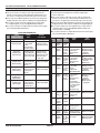
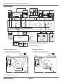
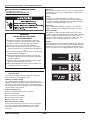
FOR SERVICE TECHNICIAN ONLY - DO NOT REMOVE OR DESTROY
Door Lock
The door will be locked when the cycle starts. The door will remain
locked until the end of a cycle or approximately 2 minutes after a
power interruption.
BASIC OPERATION OF COMMERCIAL WASHER
■ For additional information, see
www.MaytagCommercialLaundry.com
Pricing
After the door is opened following the completion of a cycle,
the display indicates the cycle price (unless set for free operation).
As coins are dropped or debit inputs arrive, the display will change
to lead the user through the initiation of a cycle.
Free Cycles
This is established by setting the cycle price to zero. When this
happens, ‘SELECT CYCLE’ will appear rather than a cycle price.
Debit Card Ready
This appliance is debit card ‘cable’ ready. It will accept a variety
of debit card systems, but does NOT come with a debit card reader.
Refer to the debit card reader manufacturer for proper washer
set-up. In models converted to a Generation 1 debit card system,
debit pulses represent the equivalent of one coin (coin 1).
IMPORTANT
Electrostatic Discharge (ESD)
Sensitive Electronics
ESD problems are present everywhere. ESD may damage
or weaken the electronic control assembly. The new control
assembly may appear to work well after repair is finished,
but failure may occur at a later date due to ESD stress.
■ Use an anti-static wrist strap. Connect wrist strap to green
ground connection point or unpainted metal in the appliance.
-ORTouch your finger repeatedly to a green ground connection point
or unpainted metal in the appliance.
■ Before removing the part from its package, touch the antistatic bag to a green ground connection point or unpainted
metal in the appliance.
■ Avoid touching electronic parts or terminal contacts; handle
electronic control assembly by edges only.
■ When repackaging failed electronic control assembly in antistatic bag, observe above instructions.
Display
After the washer has been installed and plugged in, the display will
show ‘0 MINUTES’. Once the washer has been plugged in and the
washer door opened and closed, the display will show the price. In
washers set for free cycles, the display will flash ‘SELECT CYCLE’.
GENERAL USER INFORMATION
‘----’ Inoperative State
These lines on the display indicate the appliance is inoperative.
Enter set-up mode to view diagnostic code.
‘0 Minutes’ showing in display
This condition indicates the appliance cannot be operated. Coins
dropped or debit inputs during this condition will be stored in escrow
but cannot be used until normal operation is restored by opening
and closing the door. If a door switch fails, it must be replaced before
normal operation can be restored.
Cold Start (initial first use)
Appliance is programmed at the factory as follows:
■ 14 minute wash period
■ 3 rinses (extra rinse not enabled)
■ $1.75 wash price (PD models)
■ $0.00 wash price (PR models)
Warm Start (after power failure)
A few seconds after power is restored, if a cycle was in progress
at the time of the power failure, ‘RESELECT CYCLE’ will flash
in the display, indicating the need for a key press to restart
the washer.
PART NO. W10165326A
PAGE 1
FOR SERVICE TECHNICIAN ONLY - DO NOT REMOVE OR DESTROY
CONTROL SET-UP PROCEDURES
CODE
IMPORTANT: Read all instructions before operating.
■ PD/PS Models: Insert access door key, turn, and lift to remove
access door.
■ PR Models: Once the debit card reader is installed (according to
the reader manufacturer’s instructions), the set-up mode can be
entered by inserting a manual set-up card (supplied by the reader
manufacturer) into the card slot. If a manual set-up card is not
available, manual set-up mode can be entered by removing
connector AA1 on the circuit board.
IMPORTANT: Unplug washer or disconnect power before opening
the console. To access connector AA1:
Unplug washer or disconnect power.
Open console, disconnect plug on AA1, close console.
Plug in washer or reconnect power.
The washer is now in the set-up mode. The lower fabric setting key
pads and the digital display are used to set up the controls. The
display can contain 4 numbers and/or letters and a decimal point.
These are used to indicate the set-up codes and related code
values available for use in programming the appliance.
714
714
How to use the key pads to program the controls
1. The PERMANENT PRESS key pad is used to adjust the values
associated with set-up codes. Pressing the key pad will change
the value by increments. Rapid adjustment is possible by holding
the key pad down.
2. The WOOLENS key pad will advance you through the set-up
codes. Pressing the key pad will advance you to the next
available set-up code. Holding the key pad down will automatically
advance through the set-up codes at a rate of one (1) per second.
3. The DELICATES & KNITS key pad is used to select or deselect options.
Start Operating Set-Up
Before proceeding, it is worth noting that, despite all of the options
available, an owner can simply choose to uncrate a new commercial
washer, hook it up, plug it in, and have a unit that operates. Units
are preset at the factory for a 14-minute wash period and 3 rinses
(no extra rinse).
SET-UP CODES
The WOOLENS key pad will advance you from code to code.
■ The PERMANENT PRESS key pad will change the code value.
■ The DELICATES & KNITS key pad will select or deselect options.
FOR PR MODELS: The set-up codes are the same as for the ‘PD’
models except where noted.
The set-up code is indicated by the one or two left-hand characters. The
set-up code value is indicated by the two or three right-hand characters.
■
CODE
WASH LENGTH
This is the number of minutes for WASH. Unit comes from the
factory preset with 14 minutes. Choose from 9-17 minutes by
pressing the PERMANENT PRESS key pad.
Press the WOOLENS key pad once to advance to next code.
ADDITIONAL RINSE OPTION
800
This option is either SELECTED ‘ON’ or NOT SELECTED ‘OFF’.
Not Selected ‘OFF’.
800
Selected ‘ON’.
8A8
Press the DELICATES & KNITS key pad once for this selection.
Press
the
WOOLENS
key pad once to advance to next code.
CYCLE COUNTER OPTION
900
This option is either SELECTED ‘ON’ or NOT SELECTED ‘OFF’.
Not Selected ‘OFF’.
900
Selected ‘ON’ and not able to be deselected.
90C
Press the DELICATES & KNITS key pad 3 consecutive times
to select ‘ON’. Once selected ‘ON’ it cannot be deselected.
Press the WOOLENS key pad once to advance to next code.
MONEY COUNTER OPTION
1. 0 0
This option is either SELECTED ‘ON’ or NOT SELECTED ‘OFF’.
1. 0 0
Not Selected ‘OFF’.
Selected ‘ON’.
1. 0 C
Press the DELICATES & KNITS key pad 3 consecutive times
to select ‘ON’ and 3 consecutive times to remove (Not
Selected ‘OFF’.) Counter resets by going from ‘OFF’ to ‘ON’.
Press
the
WOOLENS
key pad once to advance to next code.
Selected ‘ON’ and not able to be deselected.
1. C 0
To select ‘ON’ and not able to be deselected, first select ‘ON’, then
within two seconds press the DELICATES & KNITS key pad twice,
the PERMANENT PRESS key pad once, and exit the set-up mode.
SPECIAL PRICING OPTION
2. 0 0
This option is either SELECTED ‘ON’ or NOT SELECTED ‘OFF’.
Not Selected ‘OFF’.
2. 0 0
Selected ‘ON’. Press the DELICATES & KNITS key pad once
2. S P
for this selection.
If SPECIAL PRICING OPTION is selected, you have access to codes ‘3.XX’
through ‘9.XX’.
Press the WOOLENS key pad once to advance to next code.
EXPLANATION
60 7
60 7
REGULAR CYCLE PRICE
Represents the number of quarters (coin 1); may adjust from 0-39.
(See VALUE OF COIN 1.) Advance from 0-39 by pressing the
PERMANENT PRESS key pad. Factory preset for 7 quarters = $1.75.
PR MODELS ONLY: Factory preset for 0 quarters.
PS MODELS ONLY: Represents the number of push-in actuations
of the coin slide to start the washer.
601 setting would represent one coin slide actuation.
Press the WOOLENS key pad once to advance to next code.
PART NO. W10165326A
EXPLANATION
PAGE 2
OPTIONS TO USE IF SPECIAL PRICING IS SELECTED:
3. 0 7
3. 0 7
SPECIAL CYCLE PRICE
Represents the number of quarters (coin 1): may adjust
from 0-39. (See VALUE OF COIN 1.) Advance from 0-39 by
pressing the PERMANENT PRESS key pad. Factory preset
for 7 quarters = $1.75.
PR MODELS ONLY: Factory preset for 0 quarters.
Press the WOOLENS key pad once to advance to next code.
FOR SERVICE TECHNICIAN ONLY - DO NOT REMOVE OR DESTROY
CODE
EXPLANATION
CODE
OPTIONS TO USE IF SPECIAL PRICING IS SELECTED (cont.):
C.20
C.20
5. 0 0
5. 0 0
TIME-OF-DAY CLOCK, MINUTES
This is the TIME-OF-DAY CLOCK, minute setting; select 0-59
minutes by pressing the PERMANENT PRESS key pad.
Press the WOOLENS key pad once to advance to next code.
TIME-OF-DAY CLOCK, HOURS
6. 0 0
NOTE: Uses military time or 24 hr. clock.
This is the TIME-OF-DAY CLOCK, hour setting; select 0-23 hours
6. 0 0
by pressing the PERMANENT PRESS key pad.
Press the WOOLENS key pad once to advance to next code.
SPECIAL PRICE START HOUR
7. 0 0
NOTE: Uses military time or 24 hr. clock.
This is the start hour; 0-23 hours. Select START HOUR by pressing
7. 0 0
the PERMANENT PRESS key pad.
Press
the
WOOLENS
key pad once to advance to next code.
SPECIAL PRICE STOP HOUR
8. 0 0
NOTE: Uses military time or 24 hr. clock.
This is the stop hour; 0-23 hours. Select STOP HOUR by pressing
8. 0 0
the PERMANENT PRESS key pad.
Press the WOOLENS key pad once to advance to next code.
SPECIAL PRICE DAY
9. 1 0
This represents the day of the week and whether special pricing
9. 1 0
is selected for that day. A number followed by ‘0’ indicates no
selection that particular day (9.10). A number followed by an ‘S’
indicates selected for that day (9.1S). To change the value of ‘0’
and ‘S’, use the DELICATES & KNITS key pad.
Days of the week (1-7) are selected by pressing the PERMANENT
PRESS key pad.
When exiting setup code ‘9’, the display must show current day
of week:
DISPLAY
DAY OF WEEK
CODE (selected)
10
Day 1 = Sunday
1S
20
Day 2 = Monday
2S
30
Day 3 = Tuesday
3S
40
Day 4 = Wednesday
4S
50
Day 5 = Thursday
5S
60
Day 6 = Friday
6S
70
Day 7 = Saturday
7S
Press
the
WOOLENS
key
pad
once
to
advance
to
next
code.
A. 00
VAULT VIEWING OPTION
This option is either SELECTED ‘ON’ or NOT SELECTED ‘OFF’.
Not Selected ‘OFF’.
A. 00
Selected ‘ON’. Press the DELICATES & KNITS key pad once for
A.SC
this selection. When selected, the money and/or cycle counts
will be viewable (if counting is selected) when the coin box
is removed.
Press the WOOLENS key pad once to advance to next code.
VALUE OF COIN 1
6.05
This represents the value of coin 1 in number of nickels:
6.05
05 = $0.25.
By pressing the PERMANENT PRESS key pad you have the option
of 1-199 nickels.
PS MODELS ONLY: Represents the total vend price in nickels.
Example: b.30 is equal to $1.50.
Press the WOOLENS key pad once to advance to next code.
PART NO. W10165326A
EXPLANATION
VALUE OF COIN 2
This represents the value of coin 2 in number of nickels:
20 = $1.00.
PR MODELS ONLY: Factory preset for $0.25.
By pressing the PERMANENT PRESS key pad you have the option
of 1-199 nickels.
Press the WOOLENS key pad once to advance to next code.
COIN SLIDE OPTION
8.00
This option is either SELECTED ‘ON’ or NOT SELECTED ‘OFF’.
Not Selected ‘OFF’.
8.00
Selected ‘ON’. Press the DELICATES & KNITS key pad
8. CS
3 consecutive times for this selection.
When coin slide mode is selected, set ‘b.’ equal to value of slide
in nickels. Set step 6 (regular cycle price) and step 3 (special cycle
price) to number of slide operations. If the installer sets up ‘CS’
on a coin drop model, it will not register coins.
Press the WOOLENS key pad once to advance to next code.
ADD COINS OPTION
E. 0 0
This option is either SELECTED ‘ON’ or NOT SELECTED ‘OFF’. This
option causes the customer display to show the number of coins
(coin 1) to enter, rather than the dollars-and-cents amount.
Not Selected ‘OFF’.
E. 0 0
Selected ‘ON’. Press the DELICATES & KNITS key pad
E. A C
3 consecutive times for this selection.
Press the WOOLENS key pad once to advance to next code.
ENHANCED PRICING OPTION
F. 0 0
Not Selected ‘OFF’.
F. 0 0
Cycle-Based pricing enabled. This option allows configuration
F. CP
of different prices for cold, warm, and hot water cycles.
Super Cycle pricing enabled. This option allows customers
F. S 8
to upgrade cycles by depositing extra money. Setup codes
‘H.’ and ‘h.’ will be displayed only when this option is enabled.
Press the DELICATES & KNITS key pad for this selection.
Press the WOOLENS key pad once to advance to next code.
SUPER CYCLE UPGRADE PRICE
H .0 1
(Skipped unless super cycle pricing is enabled.)
This represents the number of coin 1 required to upgrade a
H .0 1
base cycle to a super cycle. Advance from 0-39 by pressing
the PERMANENT PRESS key pad.
Press
the
WOOLENS
key pad once to advance to next code.
SUPER CYCLE TYPE
H .0 1
(Skipped unless super cycle pricing is enabled.)
This represents the super cycle upgrade option. Press the
H .0 1
PERMANENT PRESS key pad to step through upgrade options 1
through 3 as follows:
01 - enhanced wash, extra 3 minutes of wash tumble in addition
to the programmed wash time.
02 - extra rinse for all cycles.
03 - both 01 and 02.
Press
the
WOOLENS
key pad once to advance to next code.
PAGE 3
FOR SERVICE TECHNICIAN ONLY - DO NOT REMOVE OR DESTROY
CODE
J. C 8
J. C 8
J. C 8
J. C 8
If cycle counter (90C) is selected, the following is true:
EXPLANATION
COIN/DEBIT OPTION
Both coin & debit selected.
Coins selected, debit disabled.
Debit Card selected, coins disabled. Press the DELICATES & KNITS
key pad 3 consecutive times for this selection.
Enhanced Debit is self-selected when a Generation 2 card reader
J. E 8
is installed in the washer. The Ed option cannot be manually
selected or deselected.
Press the WOOLENS key pad once to advance to next code.
PRICE SUPPRESSION OPTION
L. 0 0
This option causes the customer display to show ‘ADD’ or
‘AVAILABLE’ rather than the amount of money to add. (Used
mainly in debit installations.)
Not Selected ‘OFF’.
L. 0 0
Selected ‘ON’. Press the DELICATES & KNITS key pad once
L. PS
for this selection.
Press the WOOLENS key pad once to advance to next code.
CLEAR ESCROW OPTION
8. C E
When selected, money held in escrow for 30 minutes without
further escrow or cycle activity will be cleared.
Not selected ‘OFF’.
8.00
Selected ‘ON’. Press the DELICATES & KNITS key pad once
8. C E
for this selection.
Press
the
WOOLENS
key pad once to advance to next code.
8. 800 TOP SPIN SPEED RPM
8. 800 This can be selected from the following spin speeds: 600 rpm,
750 rpm, 800 rpm, 1000 (displays as 999) rpm. Step between
speeds by pressing the PERMANENT PRESS key pad. Factory
preset for 800 rpm.
Press the WOOLENS key pad once to advance to next code.
PENNY INCREMENT OFFSET
0. 0 0
This represents the penny increment price offset used in
0. 0 0
Generation 2 (Enhanced Debit) PR models. Choose from 0-4
pennies by pressing the PERMANENT PRESS key pad.
Press
the
WOOLENS
key pad once to advance to next code.
8 1.00 PREWASH LENGTH
8 1.00 This is the number of minutes of PREWASH. Choose 0 to disable
the prewash or select between 2 and 7 minutes by pressing the
PERMANENT PRESS key pad.
Press the WOOLENS key pad once to advance to next code.
82.03 FINAL SPIN LENGTH
82.03 This is the number of minutes of final high speed spin. Choose
from 3-8 minutes by pressing the PERMANENT PRESS key pad.
Press
the
WOOLENS
key pad once to advance to next code.
PART NO. W10165326A
100 Represents the number of cycles in HUNDREDS. 1 02 = 200
200 Represents the number of cycles in ONES.
2 25 = 225
TOTAL = 225
cycles
This is “VIEW ONLY” and cannot be cleared.
Press the WOOLENS key pad once to advance
to next code.
If money counter (1.0C or 1.C0) is selected, the following is true:
300 Number of dollars in HUNDREDS.
3 01 = $100.00
400 Number of dollars in ONES.
4 68 = $168.00
500 Number of CENTS.
5 75 = $100.75
TOTAL = $168.75
END OF SET-UP PROCEDURES
EXIT FROM SET-UP MODE
■
■
PAGE 4
PD Models: Reinstall access door.
PR Models:
Unplug washer or disconnect power.
Open console, reinsert plug into AA1, close console.
Plug in washer or reconnect power.
FOR SERVICE TECHNICIAN ONLY - DO NOT REMOVE OR DESTROY
DIAGNOSTIC GUIDE
FAILURE/ERROR DISPLAY CODES
Before servicing, check the following:
■ Make sure there is power at the wall outlet.
■ Are both hot and cold water faucets open and water supply
hoses unobstructed?
■ Check all connections before replacing components. Look for
broken or loose wires, failed terminals, or wires not pressed
into connections far enough.
■ A potential cause of a control not functioning is corrosion on
connections. Observe connections and check for continuity
with an ohmmeter.
■ Connectors: Look at top of connector. Check for broken or loose
wires. Check for wires not pressed into connector far enough
to engage metal barbs.
■ Resistance checks must be made with power cord unplugged
from outlet, and with wiring harness or connectors disconnected.
ACCU
TRAC® WASHER
DISPLAY DISPLAY
d
6
F
01
d
11
F
11
WASHER DIAGNOSTIC MODE
To enter the ‘Washer Diagnostic Mode,’ first enter ‘Start Operating
Set-Up.’ Then press and hold the DELICATES & KNITS key pad
for 1 second while in any of the set-up codes one through six,
anytime a diagnostic code is present, or while dAS displays
if operating with Maytag Data Acquisition set-up.
On entry to diagnostic mode, the entire display will flash, a cycle
in process is canceled, money in escrow is cleared, and diagnostic
codes are cleared. If a diagnostic code persists, it must be
corrected before the following cycle options are permitted.
There are five possible ways to initiate cycle activity from diagnostic
mode as follows:
1. Clean Washer cycle – With the entire display flashing, this cycle
is started by pressing the BRIGHTS keypad.
Use the Clean Washer cycle once a month to keep the inside
of your washer fresh and clean. This cycle uses a higher water
level. Use with AFFRESH™ washer cleaner tablet or liquid
chlorine bleach to thoroughly clean the inside of your washer.
This cycle should not be interrupted. See ‘WASHER CARE’ section.
IMPORTANT: Do not place garments or other items in the
washer during the Clean Washer cycle. Use this cycle with
an empty wash drum.
2. Cycle Credit – With the entire display flashing, a cycle may be
credited by pressing the PERMANENT PRESS key pad (CC will
display). When the service mode is exited, ‘SELECT CYCLE’ will
be displayed unless the end-of-cycle door opening is required.
3. Manual Load Test Cycle – With the entire display flashing, this
cycle is started by pressing the WHITES key pad. This cycle
provides more typical full length fills, tumbles, drains, and actuator
dispenser movement, allowing for a more thorough analysis of the
washer operation, including pressure switch behavior.
4. Quick Spin Cycle – With the entire display flashing, this cycle is
started by pressing the COLORS key pad. This cycle provides a
method to quickly drain and spin (remove water from the washer),
if desired.
5. History Overview Test Cycle – With the entire display flashing,
this cycle is started by pressing the WOOLENS key pad. This
cycle provides a quick verification that the cold and hot water
valves, dispensers, and pump motor are working, as well as
actuator dispenser movement. It also includes drain and spin
operations.
Pressing the DELICATES & KNITS key pad will exit diagnostic mode
and cancel a diagnostic cycle in process.
PART NO. W10165326A
PAGE 5
EXPLANATION AND RECOMMENDED PROCEDURE
EEPROM ERROR
A communication error between the Central Control
Unit (CCU) and the EEPROM onboard the CCU occurred.
Possible Causes/Procedure
■ A power glitch may cause this error.
– Unplug washer or disconnect power
for two minutes.
– Verify CCU operation by running a Diagnostics Test
or any cycle.
PUMP DRIVE ERROR
The pump driver fails to activate.
Possible Causes/Procedure
■ Replace CCU board.
MAIN RELAYS ERROR
One of the main relays is not working properly.
Possible Causes/Procedure
■ The relay might be soldered or always open.
– Replace CCU board.
MOTOR CONTROL UNIT ERROR
The Motor Control Unit has internal failure, repeating
under or over voltage, or over current conditions. If
failure occurs during high-speed spin, the door unlocks
after 3 minutes.
Possible Causes/Procedure
1. Unplug washer or disconnect power.
2. Check wire harness connections between the drive
motor and the Motor Control Unit (MCU), and
between the MCU and the Central Control Unit (CCU).
Check the motor and do a continuity test.
3. Plug in washer or reconnect power.
4. Check the MCU by looking for operations of the
drive motor.
5. Check the drive motor for powered rotations.
6. Replace MCU board.
FOR SERVICE TECHNICIAN ONLY - DO NOT REMOVE OR DESTROY
ACCU
TRAC® WASHER
DISPLAY DISPLAY
d
7
d
8
F
20
F
21
EXPLANATION AND RECOMMENDED PROCEDURE
NO WATER DETECTED ENTERING
MACHINE OR PRESSURE SWITCH TRIP
NOT DETECTED
The pressure switch is not tripped after 6 minutes.
Possible Causes/Procedure
■ If there is no water in the unit:
– Make sure that both valves at the water source(s)
are turned on all the way.
– Check for plugged or kinked inlet hoses
or plugged screens in the inlet valves.
– Verify inlet valve operation.
■ If there is water in the unit:
– Verify drain pump operation.
– Verify that the pressure switch hose is in good
condition and properly connected to tub and
pressure switch.
1. Verify there is not a siphon problem.
2. Press STOP twice to clear the display. The machine
will drain for 3 minutes before unlocking the door.
3. Unplug washer or disconnect power.
4. Verify wire harness connections to inlet valves,
pressure switch, drain pump, and Central Control
Unit (CCU).
5. Check all hoses for possible leaks.
6. Plug in washer or reconnect power.
7. Verify pressure switch operation.
8. Verify CCU operation by running a Diagnostic Test
or any cycle.
LONG DRAIN
If the drain time exceeds 8 minutes, the water valves
turn off.
NOTES:
■ After 4 minutes, the ‘Sd’ error will be displayed,
then 4 minutes later the ‘F/21’ error code will
be displayed.
■ Press STOP two times to clear the display.
Possible Causes/Procedure
1. Check the drain hose and make sure it is not
plugged or kinked.
2. Unplug washer or disconnect power.
3. Check the electrical connections at the pump
and make sure the pump is running.
4. Check the drain pump for foreign objects.
5. Plug in washer or reconnect power.
6. If the above does not correct the problem,
go to step 7.
7. Unplug washer or disconnect power.
8. Replace the pump.
PART NO. W10165326A
ACCU WASHER
TRAC® DISPLAY
DISPLAY
d
17
F
22
d
24
F
24
d
12
F
25
d
4
F
26
PAGE 6
EXPLANATION AND RECOMMENDED PROCEDURE
DOOR LOCK ERROR
After 6 failed attempts to lock the door.
Possible Causes/Procedure
■ Door lock mechanism is broken or removed
from door.
■ Door switch/lock unit failure.
1. Unplug washer or disconnect power.
2. Check door switch/lock unit.
3. Check the wire harness connections to the door
switch/lock unit and Central Control Unit (CCU).
WATER TEMPERATURE SENSOR ERROR
If the water temperature sensor (NTC) value is out
of range (23°F to 217°F [-5°C to 103°C]) during the
water-heating step of the WASH cycle.
NOTE: To find correct Ohm reading, refer to the
Water Temperature Sensor section, page 12.
Possible Causes/Procedure
1. Unplug washer or disconnect power.
2. Check the water temperature sensor and
connection to it.
3. Check resistance of heating element, if present
on this model. (abnormal = infinity)
4. Refer to the Water Temperature Sensor section,
page 12.
DRIVE MOTOR TACHOMETER ERROR
If the control is unable to properly detect motor speed,
the machine shuts down. If a failure occurs during
high-speed spin, the door unlocks after 3 minutes.
Possible Causes/Procedure
1. Verify that the shipping system, including
shipping bolts, spacers, and cables, are removed.
2. Unplug washer or disconnect power.
3. Check wire harness connections between the
drive motor and the Motor Control Unit (MCU),
and between the MCU and the Central Control
Unit (CCU).
4. Plug in washer or reconnect power.
5. Check the MCU by looking for operations of the
drive motor.
6. Check the drive motor for powered rotations.
DOOR SWITCH ERROR
If the door has not been opened for 3 consecutive
cycles or the door switch is open while the door
is locked for more than 5 seconds.
Possible Causes/Procedure
■ Door not opened during 3 consecutive cycles.
1. Open and close the door.
2. Verify CCU operation by running a Diagnostic Test
or any cycle.
■ Door switch open while door is locked.
1. Push the door and check if it is completely closed.
2. Verify CCU operation by running a Diagnostic Test
or any cycle.
FOR SERVICE TECHNICIAN ONLY - DO NOT REMOVE OR DESTROY
ACCU
TRAC® WASHER
DISPLAY DISPLAY
d
21
d
20
d
19
F
27
F
28
F
29
EXPLANATION AND RECOMMENDED PROCEDURE
OVERFLOW CONDITION
If the overflow contact on the pressure switch is
closed for more than 60 seconds, an Overflow
Condition occurs. In an overflow condition, the door
remains locked and the drain pump runs constantly,
even if STOP is pressed twice and the display is
cleared. Turn off hot and cold water faucets and
unplug the unit before servicing.
Possible Causes/Procedure
1. Check the drain hose and make sure it is not
plugged or kinked.
2. Unplug washer or disconnect power.
3. Check wire harness connections to the drain
pump, pressure switch, water inlet valve,
and Central Control Unit (CCU).
4. Check/clean drain pump filter of foreign objects.
5. Check for drain pump failure.
6. Check the inlet valve for proper shut off.
7. Check the pressure switch for proper operation.
SERIAL COMMUNICATION ERROR
The communication between the Central Control
Unit (CCU) and the Motor Control Unit (MCU)
cannot be sent correctly.
Possible Causes/Procedure
1. Unplug washer or disconnect power.
2. Check wire harness connections to the MCU,
the motor, and Central Control Unit (CCU).
– Check connections of the CCU board within
the housing.
– Make sure all grounding switches are engaged.
3. Check the drive system for any worn or failed
components.
4. Plug in washer or reconnect power.
5. Verify CCU operation by running a Diagnostic
Test or any cycle.
6. Check the MCU by looking for operations of the
drive motor.
7. Check the drive motor for powered rotations.
8. Check that the serial harness at the MCU is not
mounted upside down. The wires should be to the
left when facing the MCU connectors.
DOOR UNLOCK ERROR
If the door unlock has failed 6 times.
Possible Causes/Procedure
■ Door lock mechanism is broken.
■ Door switch/lock unit failure.
1. Check door switch/lock unit for foreign objects.
2. Unplug washer or disconnect power.
3. Check the wire harness connections to the door
switch/lock unit and Central Control Unit (CCU).
NOTE: The door switch/lock unit can be manually
unlocked. See Manually Unlocking the Door Lock
System, page 12.
PART NO. W10165326A
ACCU
TRAC® WASHER
DISPLAY DISPLAY
d
18
F
30
d
10
F
31
d
14
F
33
d
15
rL
or
F
34
PAGE 7
EXPLANATION AND RECOMMENDED PROCEDURE
DISPENSER SYSTEM ERROR
When the dispenser motor cannot be driven to its
proper position.
Possible Causes/Procedure
1. Unplug washer or disconnect power.
2. Check mechanical linkage from dispenser motor
to the top of the dispenser.
3. Check the wire harness connections to the
dispenser motor and Central Control Unit (CCU).
4. Check dispenser motor for powered rotations.
MCU FAILURE
If the heat sink gets too hot, the Motor Control Unit
(MCU) will stop the motor, the MCU will communicate
this failure to the Central Control Unit (CCU), then the
CCU will reset the MCU. If the condition continues four
times, the F31 code will show.
Possible Causes/Procedure
1. Check for proper installation, verify the unit is
not located near a source of heat and has proper
ventilation.
2. Unplug washer or disconnect power.
3. Check the wire harness connections to the MCU,
the motor, and Central Control Unit (CCU).
4. Check the drive system for any worn or failed
components.
5. Plug in washer or reconnect power.
6. Check the MCU by looking for operations of the
drive motor.
7. Check the drive motor for powered rotations.
PUMP DRIVE SYSTEM ERROR
When the connection between pump and the
Central Control Unit (CCU) is lost.
Possible Causes/Procedure
1. Unplug washer or disconnect power.
2. Check the wire harness connections to the pump
and Central Control Unit (CCU).
3. Plug in washer or reconnect power.
4. Verify CCU operation by running a Diagnostic
Test or any cycle. Refer to the Continuity Tests
on page 12.
LOAD INSIDE DRUM DURING CLEANING
WASHER CYCLE
If, at the start of the CLEANING WASHER cycle,
a load is detected inside the drum.
NOTE: Detects by weight.
Possible Causes/Procedure
Remove clothes from drum and start the cycle again.
FOR SERVICE TECHNICIAN ONLY - DO NOT REMOVE OR DESTROY
ACCU
TRAC® WASHER
DISPLAY DISPLAY
d
22
F
70
d
23
F
71
d
3
F
73
d
3
F
74
ACCU
TRAC® WASHER
DISPLAY DISPLAY
EXPLANATION AND RECOMMENDED PROCEDURE
CENTRAL CONTROL UNIT
HEARTBEAT FAILURE
If a Central Control Unit Heartbeat Failure is displayed,
no communication is detected from the Central Control
Unit to the User Interface.
Possible Causes/Procedure
1. Check for continuity of the User Interface harness.
2. Check wire harness connection to the User Interface
and Central Control Unit.
3. Replace User Interface if drum is rotating.
4. Replace Central Control Unit if drum is not moving.
USER INTERFACE HEARTBEAT FAILURE
If a Central Control Unit Heartbeat Failure is displayed,
no communication is detected from the User Interface
to the Central Control Unit.
Possible Causes/Procedure
1. Check for continuity of the User Interface harness.
2. Check wire harness connection to the User Interface
and the Central Control Unit.
3. Replace User Interface if drum is rotating.
4. Replace Central Control Unit if drum is not moving.
UI EEPROM ERROR
A communication error between the User Interface (UI)
and the EEPROM onboard the UIC occurred.
Possible Causes/Procedure
■ A power glitch may cause this error.
– Unplug washer or disconnect power
for two minutes.
– Verify UI operation by running and cancelling
some cycles.
UIC EEPROM ERROR
CRC on EEPROM reading.
Possible Causes/Procedure
■ A power glitch may cause this error.
– Unplug washer or disconnect power
for two minutes.
– Verify UI operation by running and cancelling
some cycles.
PART NO. W10165326A
d
5
d
5
d
9
d
9
d
13
d
13
PAGE 8
EXPLANATION AND RECOMMENDED PROCEDURE
COIN 1 ERROR
The Coin Drop Sensor 1 is blocked for 8 seconds.
(Coin recognition and price display disabled while
blockage persists).
Possible Causes/Procedure
■ A coin vault full of money may cause this error.
– Take the money out of the coin vault.
■ A dirty sensor may cause this error.
– Clean the coin sensor.
■ If the problem persists:
1. Unplug the washer or disconnect power.
2. Check the wire harness connections between User
Interface (UI) and the coin sensor. Do continuity test.
3. Replace the Coins Sensor.
4. Plug in the washer or reconnect power.
5. Verify the coin drop operation.
6. If the above doesn’t solve the problem, go to step 7.
7. Unplug washer or disconnect power.
8. Replace the User Interface.
LOW VOLTAGE DETECTION ERROR
Voltage detected below 90vac for 8 seconds.
Possible Causes/Procedure
1. Unplug the washer or disconnect power.
2. Check the wire harness connection between
the User Interface and the transformer.
3. Check the wire harness connection between the
transformer and the line filter.
4. Replace the transformer.
5. Plug in the washer or reconnect power.
6. If the above doesn’t solve the problem, go to step 7.
7. Unplug washer or disconnect power.
8. Replace the User Interface.
COIN 2 ERROR
The Coin Drop Sensor 2 is blocked for 8 seconds.
(Coin recognition and price display disabled while
blockage persists).
Possible Causes/Procedure
■ A coin vault full of money may cause this error.
– Take the money out of the coin vault.
■ A dirty sensor may cause this error.
– Clean the coin sensor.
■ If the problem persists:
1. Unplug the washer or disconnect power.
2. Check the wire harness connections between User
Interface (UI) and the coin sensor. Do continuity test.
3. Replace the Coins Sensor.
4. Plug in the washer or reconnect power.
5. Verify the coin drop operation.
6. If the above doesn’t solve the problem, go to step 7.
7. Unplug washer or disconnect power.
8. Replace the User Interface.
FOR SERVICE TECHNICIAN ONLY - DO NOT REMOVE OR DESTROY
ACCU
TRAC® WASHER
DISPLAY DISPLAY
d
16
d
16
EXPLANATION AND RECOMMENDED PROCEDURE
GENERATION 2 DEBIT CARD
READER ERROR
No communication from installed debit card reader
in Generation 2 debit mode.
Possible Causes/Procedure
■ A wrong payment mode selection may cause
this problem.
– Verify that you are using a Gen2 card reader
and not a Gen1.
■ If you are using a Gen2 card reader:
1. Unplug the washer or disconnect power.
2. Check the wire harness connections between
User Interface (UI) and the debit card reader
Gen2. Do continuity test.
3. Plug in the washer or reconnect power.
4. Verify the Gen2 card reader; if possible,
use a different card reader.
5. If the above fails, go to step 6.
6. Unplug the washer or disconnect power.
7. Replace the UIC board.
If the washer is in operation mode, critical errors are indicated as four
dashes (----) in the display. When the owner or service personnel
accesses the service mode, the error will be displayed. NOTE: Errors
d5, d9, d13, and d16 will not stop the ongoing cycle, although they
will not allow another cycle to begin until the error is addressed.
DIAGNOSTIC TEST
The washer has two different modes of diagnostics:
The Manual Key Functions in Diagnostic Sub-Modes that allow
you to run diagnostic cycles, providing a more thorough analysis
of machine operation, run a Quick Drain and Spin, run or credit free
cycles to the user, or run a Clean Washer cycle.
The Help Mode that allows you to verify the help codes that are
currently present on the washer, and to check the software revision
of the CCU and UIC. Also gives you feedback of the current state
of the valves, actuators, sensors, and general state of the washer.
MANUAL KEY FUNCTIONS IN DIAGNOSTIC SUB-MODES
The washer is capable of assuming three sub-modes:
1. Code Display
2. Flashing Mode
3. Special Cycle Mode
Flashing Mode
This mode allows you to start special diagnostic cycles, run a
Quick Drain and Spin, run or credit free cycles, and run a Clean
Washer cycle.
a) Accessing the Flashing Mode:
■ Open the service door.
■ If the washer is operating with manual communications, press
DELICATES & KNITS key for 1 second, while the display shows
hundreds of cycles, ones of cycles, hundreds of dollars, ones
of dollars, hundredths of dollars (cents), or regular cycle price.
■ If the DA communications-controlled set-up has been established,
press DELICATES & KNITS key for 1 second, while the display
shows dAS.
When you access the flashing mode, the display will be blinking,
turning all the segments on and off. Any cycle in process is
cancelled, any money in customer escrow is cleared, and existing
diagnostic codes are cleared.
b) Functions of the Flashing Mode:
■ If you want to access the History Overview Test Program, press
the WOOLENS key (for a definition of this cycle, consult the
‘Special Cycle Mode’ section).
■ If you want to access the Manual Overview Test Program, press
the WHITES key (for a definition of this cycle, consult the ‘Special
Cycle Mode’ section).
■ If you want to run a Quick Drain and Spin, press the COLORS key.
■ If you want to access the Clean Washer cycle, press the BRIGHTS
key (for a description of the Clean Washer procedure, consult the
‘Washer Care’ section).
■ If you want to Credit a Free Cycle for customer, press the
PERMANENT PRESS key.
■ If you want to Exit the Flashing Mode and return to Set-up Mode,
press the DELICATES & KNITS key.
Special Cycle Mode
This mode describes the following diagnostic cycles that can be
accessed through the Flashing Mode:
a) The History Overview Test Program:
This cycle provides a quick verification that the cold and hot water
valves, dispensers, pump, and motor are working, and that there
is movement of the dispenser actuator.
b) The Manual Overview Test Program:
This cycle provides more typical full length fills, tumbles, drains, and
dispenser actuator movement, allowing for a more thorough analysis
of washer operation, including pressure switch behavior.
Code Display
a) Accessing the Code Display Mode:
This mode can be accessed only when the washer is in error state.
■ Open the service door.
■ The current F code or d code will be on display.
b) Functions of the Code Display Mode:
■ If you want to erase the current error code and access Set-up
Mode, press DELICATES & KNITS key for 1 second.
■ If you want to erase the current error code and access Flashing
Mode, press DELICATES & KNITS key for 2 seconds.
■ If you want to access Set-up Mode, without erasing the current
error, press WOOLENS key for 1 second.
The error displayed in this mode is the current error present in the washer.
PART NO. W10165326A
PAGE 9
FOR SERVICE TECHNICIAN ONLY - DO NOT REMOVE OR DESTROY
HISTORY OVERVIEW TEST PROGRAM
MANUAL OVERVIEW TEST PROGRAM
This cycle consists of 8 steps. In each step, the washer will
perform a Control Action as described in the table below. Once
the action is completed, the machine will jump to the next step.
■ Each step can be differentiated from the others by looking at the
display indication. Each step has a different message displayed.
■ If you wish to jump to the next step before the control action
is completed, press any key except DELICATES & KNITS.
■ If you wish to finish the complete History Overview Test Program,
press the DELICATES & KNITS key.
Be sure to perform the Diagnostic Test before replacing the
system components.
■ This cycle consists of 10 steps. In each step, the washer will
perform a Control Action as described in the table below. Once
the action is completed, the machine will jump to the next step.
■ Each step can be differentiated from the others by looking at the
display indication. Each step has a different message displayed.
■ If you wish to jump to the next step before the control action is
completed, press any key except DELICATES & KNITS (only
when the option is available).
■ If you wish to finish the complete Manual Overview Test Program,
press the DELICATES & KNITS key.
■
Models MAH22PDA/MAH22PRA
Step
Flashing
Display Indication
1
(no indication)
2
CCU EEPROM Version
Delicates Flashing
3
4
5
6
7
8
Control
Action
Actuators
to be Checked
Door locks.
■ Door lock system
Distribution system
is set to CLEAN
position.
Fill by cold water
inlet valve (4 liters).
■ Dispenser motor
■ Dispenser contact
■ Cold water inlet valve
Distribution system
is set to MW position.
Fill by hot water inlet
valve to Level_wash.
■ Dispenser motor
■ Dispenser contact
■ Hot water inlet valve
■ Pressure switch:
Display MCU
Software Version
Woolens Flashing
Drum executes
reversing movement
at wash speed
(30 sec).
■ Motor
■ Motor control (MCU)
Display MCU
Hardware Version
Whites Flashing
Drum executes
reversing movement
at wash speed
(30 sec).
■ Motor
■ Motor control (MCU)
Display UIC
EEPROM Version
Brights Flashing
Drain pump is ON.
■ Drain pump
Display UIC
Software Version
Colors Flashing
Drum rotates
counter-clockwise
and will ramp to the
maximum speed.
■ Motor
■ Motor control (MCU)
Permanent Press
Flashing
Stop motor to 0 rpm.
■ Motor
■ Motor control (MCU)
Display CCU
Software Version
& Knits Flashing
Step
Display
1
Delicates
segment
flashing
& Knits
segment
flashing
2
3
Level_wash
4
5
Whites
segment
flashing
Brights
segment
flashing
On
completion
only
On
key press
or if overfill
level is
detected
On
key press
or if overfill
level is
detected
On
key press
or if overfill
level is
detected
On
key press
or if overfill
level is
detected
6
Colors
segment
flashing
7
Permanent
On key
Press
press or
segment completion
flashing
Delicates
On
segment completion
flashing
only
& Knits
On key
segment
press or
flashing completion
Woolens On key press
segment
only after
flashing rpm = 0 and
door is
unlocked
8
9
10
PART NO. W10165326A
Woolens
segment
flashing
Exit
Condition
PAGE 10
On key
press or
completion
Control
Action
To be
Checked
Door locks.
■ Door lock system
Distribution system
is set to Main Wash
compartment.
Filling with both
valves.
Distribution system
is set to Bleach
compartment.
Filling only by the
Hot valve.
Distribution system
is set to Fabric
Softener
compartment.
Filling with both valves.
Distribution system
is set to Bypass
channel.
Filling only by the
Cold valve.
For model Duet
Sport HT, the Heater
is on during fill until
Level_wash is
activated
(80 minutes max.).
Drum executes
reversing movement
at wash speed
(10 min.).
Drain pump is on
(4 min.).
■ Dispenser Motor
■ Dispenser contact
■ Cold and Hot Water
Drain pump is on
(reach Level_sud
plus 10 sec.).
Drum rotates counterclockwise and ramps
up to maximum speed.
Stop motor to 0 rpm.
Door unlocks.
■ Drain Pump
Inlet Valve
■ Overfill level
■ Dispenser Motor
■ Dispenser contact
■ Cold and Hot Water
Inlet Valve
■ Overfill level
■ Dispenser Motor
■ Dispenser contact
■ Cold and Hot Water
Inlet Valve
■ Overfill level
■ Dispenser Motor
■ Dispenser contact
■ Cold Water
Inlet Valve
■ Overfill level
■ Heater element
(if equipped)
■ Motor
■ Motor Control (MCU)
■ Drain Pump
■ Motor
■ Motor Control (MCU)
■ Motor
■ Motor Control (MCU)
■ Door lock system
FOR SERVICE TECHNICIAN ONLY - DO NOT REMOVE OR DESTROY
DIAGNOSTIC TEST QUICK GUIDE
The following table summarizes key functions among the diagnostic sub-modes.
Key Functions in Diagnostic Mode Table
Key Name
on Interface
DELICATES &
KNITS
Generic
Key Function
Mode Select
Function in Code
Display Sub-Mode
User Input
Function in Flashing
Sub-Mode
Function in Cycle
Running Sub-Mode
Press for 1 second
Erase codes and
enter set-up mode.
Press for 2 seconds
Erase diagnostic codes
and begin diagnostic
flashing mode.
Enter set-up mode.
Cancel cycle, enter
set-up mode.
WOOLENS
Enter/Advance
Press for 1 second
Exit diagnostic mode
and enter set-up mode
without erasing code(s).
Access History Overview
Test Program
Go to next step.
PERM. PRESS
Slew
Press for 1 second
Inactive
Credit a customer cycle.
Go to next step.
WHITES
None
N/A
Inactive
Access Manual Load
Test Cycle.
Go to next step.
COLORS
None
N/A
Inactive
Access a Quick Spin.
Go to next step.
BRIGHTS
None
N/A
Inactive
Access Clean Cycle.
Go to next step.
Help Mode Submenu
HELP MODE
This mode is used to verify the behavior of the washer along the
operation of a normal cycle. It allows you to know the current status
of many switches, actuators, valves, and relays. It also reports the
current values of the drum speed, unbalance value, and power
used by the MCU.
a) Accessing the Help Mode from Manual Communication:
■ Open the service door.
■ Press the WOOLENS key until the special pricing option mode
(2.XX) is on display.
■ Press the PERMANENT PRESS key.
■ Press the WOOLENS key to move to the next option.
b) Accessing the Help Mode if the DA Communication
Has Been Established:
■ Open the service door.
■ The message dAS will appear in the display.
■ Press the PERMANENT PRESS key.
■ Press the WOOLENS key to move to the next option.
After this procedure, the washer will access the Help Mode
sub-menu.
Step
Display
Indication
1
1h.XX
Help Code 1, where XX is the help code number.*
2
2h.XX
Help Code 2, where XX is the help code number.*
3
3h.XX
Help Code 3, where XX is the help code number.*
4
1.X##
Error history code 1, where X is the F or d
code, and XX is the code number.**
5
2.X##
Error history code 2, where X is the F or d
code, and XX is the code number.**
6
3.X##
Error history code 3, where X is the F or d
code, and XX is the code number.**
7
4.X##
Error history code 4, where X is the F or d
code, and XX is the code number.**
8
SC.XX
CCU software revision, where X is the software
revision number.
9
EC.XX
CCU EEPROM revision, where XX is the EEPROM
revision number.
10
SU.XX
UI software revision, where XX is the
software number.
11
EU.XX
UI EEPROM revision, where XX is the
EEPROM number.
12
SPIN.XXX
13
P.XXX
The relative amount of power requested by the
motor, where XXX is the value.
14
U.XXX
The unbalance in the system, where XXX is the
unbalance value.***
15
Po.XX
The dispenser position – the displayed positions
are: 00 = Detergent; 01 = Bleach; 02 = Softener;
03 = Clean; FF = dispenser in movement.
Explanation
The current speed of the drum, displayed in rpm.
* To erase the help 3 help code, press DELICATES & KNITS key.
**The Errors displayed in this section are the history errors that have occurred in the washer (not necessarily an error that
is in progress). The current error is displayed in the MANUAL KEY FUNCTION IN DIAGNOSTIC SUB-MODE.
*** The values 255 and 254 are reserved numbers for specific cases. (255 = unbalance has not been calculated yet,
254 = unbalance could not be calculated).
PART NO. W10165326A
PAGE 11
FOR SERVICE TECHNICIAN ONLY - DO NOT REMOVE OR DESTROY
Water Temperature Sensor
HELP MODE SYMBOLS AND ELEMENTS
1. Unplug washer or disconnect power.
2. Disconnect the wire harness from the water temperature sensor
and measure the resistance of the sensor. Use the following table.
An abnormal condition is an open circuit.
Along with the 15 steps of the help mode, symbols and elements
are mapped, at all times, to reflect the state of various inputs
and outputs.
Display
Symbol
Description
Temperature
Results
35.9 kΩ
9.7 kΩ
6.6 kΩ
WASH
Water sensed at wash level.
*
Low voltage present (below about
90 VAC).
32°F (0°C)
86°F (30°C)
104°F (40°C)
Circle above digit
Door closed.
122°F (50°C)
4.6 kΩ
DOOR LOCKED
Door sensed locked.
140°F (60°C)
3.2 kΩ
COLD
Cold water relay on.
158°F (71°C)
2.3 kΩ
HOT
Hot water relay on.
203°F (96°C)
1 kΩ
OR
Door unlock.
AVAILABLE
Drain pump ON.
Manually Unlocking the Door Lock System
Key Functions in Help Mode Table
Key Name
on Interface
PERM.
PRESS
Generic
Key Function
Slew
Result While Software
Version Spins, Motor
Power, Dispenser State
Result While Help
Code Displays
Exits help code and
returns to set-up mode—
either dAS display or
or Mode 2.XX.
Exits help code
and returns to
set-up mode—
either dAS display
or Mode 2.XX.
Clears all three
help codes.
DELICATES
& KNITS
Mode
Select
Inactive—no result.
WOOLENS
Mode
Advance
Advances through next
help sub-mode.
Advances through
each help code.
Be sure to perform the Diagnostic Tests before replacing the
system components.
Pump Motor Continuity Test
Pins
Results
1 to 2
Normal = approx. 12.3 Ω
Abnormal = Infinity
Motor Continuity Test
1. Unplug washer or disconnect power.
2. Disconnect the wire harness from the motor and measure the
resistance of the motor. Use the following table:
Pins
Results
1 to 2
2 to 3
1 to 3
Normal = approx. 6.45 Ω
Abnormal = Infinity
PART NO. W10165326A
1. Unplug washer or disconnect power.
2. Remove the lower kick panel.
3. Reach up along the inside of the front and locate the bottom
of the door switch/lock unit.
4. Located on the bottom of the door switch/lock unit is a tear-drop
shaped tab.
5. Gently pull the tab down about 1/4″ or until a click is heard.
6. The door may be opened.
ELECTRONIC ASSEMBLIES REMOVAL OR REPLACEMENT
IMPORTANT: Electrostatic (static electricity) discharge may cause
damage to electronic control assemblies. See page 1 for details.
NOTE: Be sure to perform the Diagnostic Tests before replacing the
control board.
To Remove Central Control Unit (CCU):
1. Unplug washer or disconnect power.
2. Remove all connectors from the CCU.
3. Lift tab at upper left corner of CCU with a flat blade screwdriver.
Slide the CCU to the rear of the washer cabinet until the two tabs
on the back of the CCU align with the keyhole notches in the
cabinet. Pull the CCU away from the side panel.
To Reassemble CCU:
1. Align the two tabs on the back of the CCU with the keyhole
notches in the cabinet.
2. Slide the CCU forward until the tab at the rear of the CCU locks
into place.
3. Reconnect the wire harness.
To Remove the User Interface:
1. Unplug washer or disconnect power.
2. Disconnect the user interface assembly wire harness
from the CCU.
3. Remove the dispenser drawer.
4. Remove the four front screws in the sides of the user interface.
PAGE 12
FOR SERVICE TECHNICIAN ONLY - DO NOT REMOVE OR DESTROY
5. Check carefully for any hot circuits on the board, and wait until
they cool down.
6. Disconnect the user interface power harness, and the coin vault
and service switch harness.
7. For coin drop models, disconnect the coin 1 (and coin 2, if
provided) wire harness.
8. For card reader models, disconnect the card reader harness.
To Remove Motor Control Unit (MCU):
1. Unplug washer or disconnect power.
2. Remove wire harness cover and disconnect the wire harness
from the MCU.
3. With a flat blade screwdriver, lift the front tab up and slide the
MCU to the rear.
To Remove Line/Interference Filter:
1. Unplug washer or disconnect power.
2. Disconnect the three connectors from the line filter and
power cord.
3. Remove the screw that secures the line filter to the top brace.
4. Slide the filter toward the center of the unit to release tabs.
WASHER CARE
Cleaning the door seal:
1. Open the washer door and remove any clothing or items
from the washer.
2. Inspect the gray colored seal between the door opening and the
basket for stained areas. Pull back the seal to inspect all areas
under the seal and to check for foreign objects.
3. If stained areas are found, wipe down these areas of the seal,
using the procedure that follows:
a) Mix a dilute solution, using 3/4 cup (177 mL) of liquid
chlorine bleach, and 1 gal. (3.8 L) of warm tap water.
b) Wipe the seal area with the dilute solution, using a damp cloth.
c) Let stand 5 minutes.
d) Wipe down area thoroughly with a dry cloth and let the washer
interior air dry with door open.
IMPORTANT:
■ Wear rubber gloves when cleaning for prolonged periods.
■ Refer to the bleach manufacturer’s instructions for proper use.
Begin procedure:
1. Open the washer door and remove any clothing or items
from the washer.
2. Be sure the door is closed.
3. Open the dispenser drawer and immediately add 2/3 cup
(160 mL) of liquid chlorine bleach to the bleach compartment.
NOTE: Do not add any detergent to this cycle. Use of more than
2/3 cup (160 mL) of bleach will cause product damage over time.
4. Be sure dispenser drawer is closed.
5. To start the cleaning cycle, refer to the Special Cycle Mode.
NOTE: The basket will rotate, then the door will unlock,
lock again, and then the cycle will continue.
■ The machine will not fill, but the basket will rotate while the
washer runs a short sensing cycle. This will take approximately
3 minutes.
6. The cycle will determine if clothing or other items are in the washer.
a) If no items are detected in the washer, it will proceed to step 7.
b) If any items are detected in the washer, four dashes ‘- - - -’
will appear in the display. When you access the service set-up
mode, ‘rL’ or ‘F/34’ will be displayed. Cancel the cycle, then
repeat steps 1, 2, and 5 to start the cycle again.
7. Once the cycle has begun, allow the cycle to be completed.
8. After the cycle is complete, leave the door open slightly to allow
for better ventilation and drying of washer interior.
Always do the following to maintain washer freshness:
Use only HE High Efficiency detergent.
Leave the door slightly open after each cycle to allow for better
ventilation and drying of washer interior.
■ Repeat the cleaning procedure monthly, using 2/3 cup (160 mL)
of liquid chlorine bleach.
■ If the procedure does not sufficiently improve washer freshness,
please evaluate your installation and usage conditions for
other causes.
■
■
Washer Maintenance Procedure
This washer has a special cycle that uses higher water volumes
in combination with liquid chlorine bleach to thoroughly clean the
inside of the washer.
NOTES:
■ Read these instructions completely before beginning the cleaning
process.
■ If necessary, the cleaning cycle may be interrupted. With the
machine empty, run a rinse cycle or a partial wash cycle to
thoroughly rinse the remaining bleach from the washer. Failure
to do so will cause damage to the washer and to clothing
added for the next cycle.
■ To stop the cleaning cycle, refer to the Special Cycle Mode.
PART NO. W10165326A
PAGE 13
FOR SERVICE TECHNICIAN ONLY - DO NOT REMOVE OR DESTROY
WIRING DIAGRAM
DRIVE MOTOR
Moteur d’entraînement
N
WAX MOTOR
Moteur de l’actionneur
L
DRAIN PUMP
Pompe
de vidange
DOOR LOCK/SWITCH
Contacteur/verrou de porte
DLS
Lock Unlock
Verrouillage Déverrouillage
IF
DISPENSER
Motor Switch
Distributeur
contacteur moteur
DS
2
DL3
1
DS2
1 2
2
DLS2
1
3
HE2
2
1
HR2
HR1
2
DR1
K1
VH
VC
MOTOR CONTROL UNIT (MCU)
Module de commande du moteur
L2
IF2
1
INLET VALVES
Électrovannes (entrées)
L1
N1
MS2
1
MI3
1
2
2
3
DP2
1
2
VH7
1
3
5
7
DI6
1
3
5 6
CENTRAL CONTROL
UNIT (CCU)
Module de commande central
L2
K2
N1
1 2 3
6 5 3 4
PR6
22 24 26 21
EE1
Battery (Optional)
Pile (en option)
(+) NC NC (-)
1 2 3 4
2
1
5
3
6
p>
USER INTERFACE
Interface utilisateur
AA6
2
AA1
1
3
4
1
2 3
4
AA4
Coin Vault
Service
Switch
Switch
Contacteur Contacteur
du service du coffre
1
2 3
AA5
Coin Detector 1
Coin Detector 2
Détecteur
de la pièce 1
Détecteur
de la pièce 2
GROUNDING SYSTEM WITHOUT HEATER
DEBIT GROUND
DEBIT POWER
ENABLE 2
ENABLE 1
AVAIL 1
AVAIL 2
p>
L_0 L_wash L_over flow L_sud
L_0 L_lavage L_remplissage excessif
L_moussage excessif
Card Reader Connector
Connecteur du lecteur de carte
2
TEMPERATURE
SENSOR
Capteur de
température
PRESSURE SWITCH
Contacteur manométrique
PDAWW models include connector AA1, AA4, and card reader connector
Modèles PDAWW comprisent connecteur AA1, AA4, et connecteur du lecteur de carte
PDAXW models include connector AA1, AA4, AA5, and card reader connector
Modèles PDAXW comprisent connecteur AA1, AA4, AA5, et connecteur du lecteur de carte
PRAWW models include card reader connector
Modèles PRAWW comprisent connecteur du lecteur de carte
S1 = GND SWITCH – FRONT Contacteur de la terre, avant
S2 = GND SWITCH – REAR Contacteur de la terre, arrière
POWER CORD
Cordon
d’alimentation
REAR
Arrière
POWER CORD
Cordon
d’alimentation
CABINET
Caisse
REAR
Arrière
S2
S2
MCU
Module de
commande
du moteur
1MΩ
1
TH2
1
GROUNDING SYSTEM WITH HEATER
S1 = GND SWITCH – FRONT Contacteur de la terre, avant
S2 = GND SWITCH – REAR Contacteur de la terre, arrière
CABINET
Caisse
6
5
4
3
2
1
2
11 14
BELT: HIGH
INSULATED
MCU
Module de
commande
du moteur
1MΩ
COURROIE :
forte isolation
Hub
Moyeu
MOTOR
Moteur
Hub
Moyeu
MOTOR
Moteur
HE*
S1
S1
FRONT
Avant
FRONT
Avant
*Heating element not present on all models
PART NO. W10165326A
PAGE 14
FOR SERVICE TECHNICIAN ONLY - DO NOT REMOVE OR DESTROY
TROUBLESHOOTING GUIDE
PROBLEM
WON’T POWER UP
TOUCH-PADS DO NOT RESPOND
WHEN PRESSED
WON’T START CYCLE
WON’T DISPENSE
WON’T FILL
PART NO. W10165326A
POSSIBLE CAUSE/TEST
NOTE: Possible Cause/Tests must be performed in the sequence shown for each problem.
1. Check that the washer is plugged into a working outlet and look for blown fuses.
2. Unplug washer or disconnect power.
3. Check continuity of line cord and line filter, and replace if necessary.
4. Check continuity of the wire harness that connects the CCU with the UI, and replace if necessary.
5. Plug in washer or reconnect power. If the washer turns on, go to step 9.
6. Check for power going from Line Filter to Central Control Unit (CCU) and to transformer, using a multimeter.
7. Check for power going from transformer to the User Interface (UI), using a power multimeter.
8. Check for CCU turning on by listening for a click in the CCU when unit is plugged in. If no click, replace CCU;
if click, replace UI.
9. Verify washer operation by running a diagnostic test or any cycle.
1. Verify the use of buttons in set-up mode. If the buttons respond, go to ‘WON’T START CYCLE’. If the
buttons don’t respond, go to next step.
2. Check the connection of the matrix key board with the user interface.
3. Replace the matrix key board.
4. Verify the washer operation by running a diagnostic test or any cycle.
1. Open and close the door. The door must be opened between consecutive wash cycles.
2. Check the door switch/lock unit using the diagnostics. See Diagnostic Test.
3. If door is locked, drain the washer.
4. Unplug washer or disconnect power.
5. Check the wire harness connection of the door lock.
6. Check the wire harness connection of the UI–CCU.
7. Plug in washer or reconnect power.
8. Verify washer operation by running a Diagnostic Test or any cycle.
1. Verify the washer is level.
2. Verify dispenser drawer is not clogged with detergent.
3. Check water connections to the unit and within the unit. Check for plugged screen in water source.
4. Check dispenser motor.
5. Unplug washer or disconnect power.
6. Check harness connections.
7. Plug in washer or reconnect power.
8. Verify washer operation by running a Diagnostic Test or any cycle.
1. Check installation. Verify hot and cold water faucets are open.
2. Check inlet valves.
3. Unplug washer or disconnect power.
4. Check water connections to the unit and within the unit. Make sure water supply hoses are unobstructed.
Check for plugged screen.
5. Plug in washer or reconnect power.
6. Check operating pressure switch.
7. Check drain pump motor.
8. Verify washer operation by running a Diagnostic Test or any cycle.
9. Check under ‘WON’T DISPENSE’ problem above.
PAGE 15
FOR SERVICE TECHNICIAN ONLY - DO NOT REMOVE OR DESTROY
TROUBLESHOOTING GUIDE
PROBLEM
POSSIBLE CAUSE/TEST
NOTE: Possible Cause/Tests must be performed in the sequence shown for each problem.
1. Verify the washer is level.
2. Check pump drain system – this could indicate a failure to drain.
3. Unplug washer or disconnect power.
4. Check operating pressure switch.
5. Check pressure switch hose.
6. Plug in washer or reconnect power.
7. Verify flow meter operation by blowing air though the part and measuring the resistance.
8. Verify washer operation by running a Diagnostic Test or any cycle.
1. Check drive belt.
2. Check drive motor.
3. Unplug washer or disconnect power.
4. Check wire harness connections.
5. Plug in washer or reconnect power.
6. Check the MCU by looking for operations of the drive motor.
1. Check drive motor.
2. Unplug washer or disconnect power.
3. Check wire harness connections.
4. Check drive belt.
5. Plug in washer or reconnect power.
6. Check the MCU by looking for operations of the drive motor.
1. Unplug washer or disconnect power.
2. Check wire harness connections.
3. Check drain pump.
4. Check drain pump motor.
5. Check that the drain hose and drain pump filter are clear of foreign objects.
6. Plug in washer or reconnect power.
7. Verify washer operation by running a Diagnostic Test or any cycle.
1. Remove shipping system.
2. Check installation.
3. Check leveling feet.
1. Check that the inlet hoses are connected properly.
2. Unplug washer or disconnect power.
3. Check the water heater and wire harness connections to it.
4. Check water temperature sensor for an abnormal condition. See the Water Temperature Sensor section, page 12.
5. Plug in washer or reconnect power.
6. Verify washer operation by running a Diagnostic Test or any cycle.
See Failure/Error Display Codes.
OVERFILLS
DRUM WON’T ROTATE
MOTOR OVERHEATS
WON’T DRAIN
MACHINE VIBRATES
INCORRECT WATER TEMPERATURE
DISPLAY FLASHING
SOFTWARE COPYRIGHTED. MANUFACTURED UNDER ONE OR MORE OF THE FOLLOWING U.S. PATENTS:
4,693,095
4,697,293
4,700,554
4,709,951
4,715,401
4,719,769
4,754,622
4,759,202
4,774,822
4,779,431
4,782,544
4,784,666
4,785,643
4,793,820
4,807,452
4,809,524
4,835,991
4,854,559
4,856,303
4,870,988
4,888,965
4,890,465
4,891,959
4,910,979
4,945,735
4,947,516
4,969,341
4,972,134
4,977,394
4,986,093
4,987,627
5,000,016
5,031,427
5,033,277
5,074,003
5,075,613
PART NO. W10165326A
5,113,542
5,130,624
5,150,588
5,154,071
5,166,568
5,167,722
5,172,573
5,177,659
5,191,667
5,191,668
5,191,669
5,193,361
5,199,127
5,199,281
5,200,684
5,205,141
5,219,370
5,233,718
5,249,441
5,255,844
5,257,901
5,259,217
5,269,160
5,271,251
5,297,403
5,305,485
5,312,138
5,314,044
5,345,637
5,345,792
5,345,793
5,359,744
5,373,715
5,460,018
5,493,745
5,504,955
5,507,053
5,515,565
5,582,039
5,582,199
5,651,278
5,671,494
5,765,404
5,784,902
5,791,167
5,836,180
5,852,942
5,875,655
5,878,602
5,883,490
5,946,946
6,065,171
6,070,282
6,105,403
6,115,863
6,125,490
6,185,774
6,212,722
6,227,013
6,227,014
6,269,666
6,347,645
6,363,563
6,393,872
6,430,971
6,505,370
6,550,292
6,564,413
6,584,811
6,591,439
6,591,638
6,637,062
PAGE 16
03/08
6,640,372
6,647,575
6,658,902
6,715,175
6,766,670
6,786,058
6,820,447
6,845,536
6,860,032
6,906,270
6,927,351
6,961,642
6,966,204
D375,390
D381,140
D423,740
D426,686
D456,572
D459,844
D463,631
D465,308
D474,566
D502,577
D511,955
SOFTWARE COPYRIGHTED. MANUFACTURED
UNDER ONE OR MORE OF
THE FOLLOWING CANADIAN PATENTS:
1,228,410
1,233,039
1,233,658
1,282,557
1,287,338
1,288,966
1,298,988
1,301,469
1,306,367
1,313,770
2,018,975
2,022,266
2,043,393
2,056,969
2,086,151
D76,618
D92,426