1
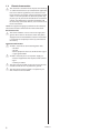
2.2
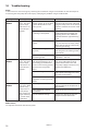
Pipe connections
Connection diameter
300 mm
Brine
Heat
De-superheater
DHP-R 20
35
28
28
DHP-R 26
42
28
28
DHP-R 35
42
35
28
DHP-R 42
42
35
28
DHP-R 21H
35
28
28
DHP-R 25H
35
28
28
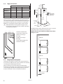
300 mm
50 mm
1490 mm (with
support legs at
highest level)
500 mm
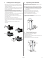
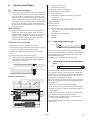
When installing in confined spaces, pipe routing on the
rear of the heat pump can be facilitated by connecting the
pipes before the pump is put in position. See the figure
below for an example on how the pipes can be routed.
⚠⚠NOTE! Remember not to tighten the pipes in the
heat pump’s panel casing as this transfers vibrations
causing noise problems.
2
1
3
4
5
6
6
5
4
600 mm
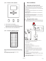
The figure above shows dimensions for one (1) installed
heat pump and the necessary service space.
Required service space when installing several heat
pumps in a row.
1. Coolant out (from HP)
2. Heat return (return line)
3. Return line hot-gas
exchanger
4. Supply line hot-gas
exchanger
5. Heat supply (supply line)
6. Coolant in (to HP)
500 mm
3
150 mm
1
2
500 mm
2.3
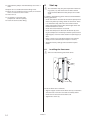
Required service space
To facilitate installation and later tests and maintenance
there must be sufficient free space around the heat pump
according to the following dimensions:
When installing several heat pumps, the dimensions
behind the heat pumps may need to be increased if there
is not enough side space. The pumps must be set-up so
that the installation can be accessed from behind.
150 mm
150 mm
300 mm
8
VMBMD302