1
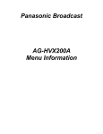
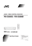
Home Theater
Power Station
with
User Guide
Important Information
CAUTION
RISK OF ELECTRIC SHOCK.
DO NOT OPEN.
Caution: To reduce the risk of
electric shock, do not remove
cover (or back). No user
serviceable parts inside. Refer
This symbol indicates "dangerous voltage" inside
the product that presents a risk of electric shock or
personal injury.
Important Safety Instructions
1. Read these instructions.
2. Keep these instructions.
personnel.
This symbol indicates important instructions
accompanying the product.
the apparatus. When a cart is used, use caution
avoid injury from tip-over.
Warning
long periods of time.
electric shock, do not expose
this product to rain or moisture.
The apparatus shall not be
exposed to dripping or splashing.
such as vases, shall be placed
on the apparatus. For indoor
use only.
manufacturer’s instructions.
8. Do not install near any heat sources such as radiators, heat registers,
9. Do not defeat the safety purpose of the polarized or grounding-type
replacement of the obsolete outlet.
the apparatus.
have fallen into the apparatus, the apparatus has been exposed to
rain or moisture, does not operate normally, or has been dropped.
indicated on the marking label. If you are not sure of the type of
16. This device must be plugged into a grounded outlet.
17. The mains plug must be accessible at all times.
Table of Contents
Chapter 1: Introduction to the
Chapter 2: Setting Up the
Home Theater Power Station ...............3 A/V Pass-Through Jacks ......................13
What does the PW1000 do
for my home theater? ....................................4
Power Conditioning ...........................................................4
Surge Protection ................................................................4
SpeedPass A/V Inputs and Outputs ...............................5
Five-Port Ethernet Switch................................................5
Tour of the PW1000...........................................7
Power and Charging / Protected Outlets..........8
SpeedPass™ Pass-Through
Inputs and Outputs ...................................... 10
Ethernet Switch .............................................. 12
What is SpeedPass? ....................................... 14
How SpeedPass works ................................................... 14
Setting Up: 2 Options ..................................... 16
TV + A/V Receiver ............................................ 17
HDMI .................................................................................. 18
Component Video and
Stereo Audio/Digital Coax Audio............................... 18
Composite Video and Stereo Audio............................. 20
MP3 Audio ........................................................................ 21
USB .................................................................................... 21
TV Only (or TV + Sound System) .................... 22
HDMI .................................................................................. 23
Component Video and
Stereo Audio/Digital Coax Audio............................... 23
Composite Video and Stereo Audio............................. 25
MP3 Audio ........................................................................ 26
USB .................................................................................... 26
Table of Contents
Chapter 3: Setting Up
Chapter 5: Using the PW1000
the Ethernet Switch ............................27 Front Panel ..........................................35
Fast Ethernet for Home Theater .................... 28
Setting Up........................................................ 28
Chapter 4: Setting Up Your Home
Theater Power and Signal Input.........30
PW1000 Back Panel Power Outlets ............... 31
Step 1: Plug the PW1000 Into a Grounded Outlet... 31
Step 2: Plug In The Always-On Outlets ...................... 32
Step 3: Plug In The Switched Outlets......................... 33
Step 4: Plug In The Back Panel Signal Inputs ........... 34
Front Panel A/V Inputs.................................... 36
What Works With These Inputs? ................................. 37
Front Panel Power and Charging Outlets ...... 39
USB Charging Outlets ..................................................... 39
Front Panel Power Indicators......................... 39
Front Panel Ethernet Port and Indicators ..... 40
Switch Indicator Lights.................................................. 40
Using the Switched Outlets ........................... 41
Chapter 6: Additional Information .....42
Troubleshooting .............................................. 43
Specifications.................................................. 46
Limited Lifetime Warranty ............................. 48
Connected Equipment Guarantee .................. 49
Safety and Regulatory Information .............. 51
Chapter 1
Introduction to the
Home Theater Power Station
» What does the PW1000 do for my home theater?
+ Performance + Protection: Power Conditioning and Surge Protection
+ Convenience: SpeedPass A/V Pass-Through Inputs and Outputs
+ Internet/Network Connectivity: Five-Port Ethernet Switch
» Tour of the PW1000
+ Power & Charging / Protected Outlets
+ SpeedPass Pass-Through Inputs and Outputs
+ Ethernet Switch
3
Chapter 1: Introduction
What does the PW1000 do for my home theater?
Performance + Protection:
Convenience: SpeedPass A/V inputs and outputs
Internet / Network Connectivity:
Performance
+ Protection
Power Conditioning
components is as clean as possible. It removes impurities and interference, giving your home theater pure,
Surge Protection
4
Chapter 1: Introduction
of electronics by subjecting their internal circuitry to undue stress.
small ones. And because the PW1000 uses high performance surge protection components, it provides a level of
protection that far surpasses most regular surge protectors on the market.
Convenience
SpeedPass A/V Inputs and Outputs
PW1000 front panel. It’s just that easy.
Internet /
Network
Connectivity
Five-Port Ethernet Switch
The Internet has definitely arrived in the home theater. And the PW1000 is the first home entertainment product
5
Chapter 1: Introduction
Front Panel
1
2
Back Panel
1
3
6
2
3
Chapter 1: Introduction
Tour of the PW1000
The front and back panels of the PW1000 offer jacks, outlets, and ports for a variety of uses in your home theater. These jacks, outlets, and
ports are grouped together according to their use. The facing page maps out these different regions on the front and back panels.
1
Power and Charging / Protected Outlets
2
SpeedPass™ Pass Through
Inputs and Outputs
3
Ethernet Switch
Front panel audio/video jacks that pass their signal through to
corresponding back panel audio/video jacks. The signal goes directly to
the home theater component that’s connected to those jacks.
output ports. The fourth Ethernet output port is on the front panel, for easy
access by devices that are just visiting your home theater.
Note:
this door.
7
Chapter 1: Introduction
Power and Charging / Protected Outlets
Front Panel
BACK PANEL SWITCHED OUTLETS
on the back panel of the PW1000. The outlets labeled ALWAYS ON on the front and back
POWER & CHARGING
visiting your home theater.
USB CHARGING
like tablets, smartphones, MP3 players, and more. The top outlet is optimized for tablets
39 for more information).
POWER
PROTECTED
8
Chapter 1: Introduction
Back Panel
SWITCHED OUTLETS
ALWAYS ON
SAT/CABLE 1 and SAT/CABLE 2 jacks let you use the PW1000 to protect your satellite and/or cable box and TV from harmful surges that
15 AMP CIRCUIT BREAKER
9
Chapter 1: Introduction
SpeedPass™ Pass-Through Inputs and Outputs
signal from the front jack through to corresponding back panel audio/video jacks. The signal goes directly to the home theater component
that’s connected to those jacks.
3
Front Panel
1
2
4
2
6
10
3
7
Back Panel
5
5
4
1
6
7
Chapter 1: Introduction
1 USB PASS THROUGH
back of the PW1000. It’s a direct link to the home theater component you have connected to that jack.
2 HDMI PASS THROUGH jack routes the high-definition video and digital audio from your portable device through to the HDMI PASS
3 VIDEO and AUDIO (L/R)
jacks on the back of the PW1000. For example, if you’ve connected the VIDEO and L and R audio jacks on the back of the PW1000 to an
component you have connected to those jacks.
4 COMPONENT VIDEO jacks route the component video signals from your portable device through to the COMPONENT VIDEO jacks on the
back of the PW1000. For example, if you’ve connected the COMPONENT VIDEO jacks on the back of the PW1000 to an input on your TV, the
have connected to those jacks.
5 AUDIO
your TV. They’re a direct link to the home theater component you have connected to those jacks.
6 DIGITAL COAX
direct link to the home theater component you have connected to that jack.
7 MP3 / AUDIO
direct link to the home theater component you have connected to those jacks.
11
Chapter 1: Introduction
Ethernet Switch
that are just visiting your home theater.
Front Panel
POWER
BACK PANEL (IN, PORT 1, PORT 2, PORT 3)
PORT 4 indicator
PORT 4
Back Panel
IN
PORT 1, PORT 2, PORT 3
12
Chapter 2
Setting Up the A/V Pass-Through Jacks
access for portable devices. SpeedPass pass-through inputs put access to the big screen or
» What is SpeedPass?
+ How SpeedPass works
» Setting Up: 2 Options
+ TV + A/V Receiver
+ TV Only (or TV + Sound System)
13
Chapter 2: Setting Up the A/V Pass-Through Jacks
What is SpeedPass?
gaming systems, tablets, and MP3 players, to your home theater. SpeedPass brings
SpeedPass eliminates this...
How SpeedPass works
sound system. All hooked up and ready to go.
discover that it’s not so easy to add to (or subtract from) your home theater. The
14
Your home theater before
Chapter 2: Setting Up the A/V Pass-Through Jacks
Your home theater with SpeedPass
SpeedPass brings all your home theater connections to the front of your home
connected, the video and audio from your portable device goes directly to the big
screen and speakers of your home theater. All you have to do is connect your home
theater to the jacks on the back of the PW1000.
PW1000
PW1000
15
Chapter 2: Setting Up the A/V Pass-Through Jacks
Setting Up: 2 Options
TV + A/V
Receiver
TV
TV Only
(or TV + Sound System)
I LISTEN...
I SWITCH components...
On the TV
On the A/V Receiver
On the A/V Receiver
On the TV
On the TV
(or on a separate
sound system)
On the TV
A/V Receiver
Blu-ray
16
I WATCH...
Satellite or cable
TV
Blu-ray
Satellite or cable
For instructions...
Chapter 2: Setting Up the A/V Pass-Through Jacks
TV + A/V Receiver
TV
A/V Receiver
Blu-ray
Satellite or cable
IMPORTANT: Remember that the more jacks you connect on the PW1000, the more jacks you’ll have available
on the front of the PW1000 for connecting portable devices.
BEFORE YOU START: Decide which inputs to use and write them down.
vacation video from your camcorder on the TV.
or
17
Chapter 2: Setting Up the A/V Pass-Through Jacks
TV
A/V Receiver
Blu-ray
TV+A/V Receiver
HDMI (TV + A/V Receiver)
The PW1000 offers one pass-through HDMI SpeedPass connection from the front to
the back HDMI jacks.
Satellite or cable
PW1000 Back Panel
To use the HDMI SpeedPass: Connect an available HDMI input on your A/V
here.
IMPORTANT: Make sure you make a note of the inputs you’re using for each
connection.
A/V Receiver
Back Panel
HDMI INPUT
Component Video and Stereo Audio/Digital Coax Audio
(TV + A/V Receiver)
The PW1000 offers one set of pass-through Component Video jacks on the front and
connect a set of audio jacks in addition to the Component Video jacks on the back
of the PW1000 to hear the audio from this source on your A/V receiver.
18
Chapter 2: Setting Up the A/V Pass-Through Jacks
available)
PW1000 Back Panel
To set up the Component Video and Audio SpeedPass:
1. Make the video connection.
Connect one set of cable ends from a component video cable to the COMPONENT
VIDEO output jacks on the back of the PW1000.
2 OR 2
1
A/V Receiver
Back Panel
CMPNT INPUT
DIGITAL
COAX
AUDIO
VIDEO
Connect the other set of cable ends to an available set of Component Video
input jacks on the back of your A/V receiver. Make sure you match the colors of
the cables to the colors of the jacks (green to Y, blue to Pb, red to Pr).
2. Make the audio connection.
IMPORTANT: Make sure you make a note of the inputs
you’re using for each connection.
Choose one of the audio options, stereo audio or digital coax. Then connect one
end of the cable(s) to the corresponding output jack on the back of the PW1000,
and connect the other end of the cable(s) to the corresponding input jack on the
back of your A/V receiver.
19
Chapter 2: Setting Up the A/V Pass-Through Jacks
TV
A/V Receiver
Blu-ray
TV+A/V Receiver
Composite Video and Stereo Audio (TV + A/V Receiver)
The PW1000 offers one set of pass-through Composite Video and Stereo Audio jacks
on the front and back of the unit.
To set up the Component Video and Audio SpeedPass:
Satellite or cable
PW1000 Back Panel
1. Make the video connection.
Connect one end of a composite video cable to the VIDEO output jack on the
back of the PW1000. Connect the other end to an available Video input jack on
the back of your A/V receiver.
2
1
2. Make the audio connection.
A/V Receiver
Back Panel
VID INPUT
R AUDIO L
VIDEO
jacks next to the VIDEO jack on the back of the PW1000, and connect the other
set of plugs to the audio input jacks next to the video input you used on the
back of your A/V receiver.
IMPORTANT: Make sure you make a note of the inputs you’re using for each
connection.
20
Chapter 2: Setting Up the A/V Pass-Through Jacks
PW1000 Back Panel
MP3 Audio (TV + A/V Receiver)
the unit. The jack on the front is a single 3.5mm stereo audio jack, commonly used on
To set up the MP3 Audio SpeedPass: Connect one set of plugs from a stereo audio
A/V Receiver
Back Panel
of plugs to an available set of audio input jacks on the back of your A/V receiver.
IMPORTANT: Make sure you make a note of the inputs you’re using for each connection.
AUDIO
USB (TV + A/V Receiver)
PW1000 Back Panel
To set up the USB SpeedPass:
Make sure you make a note of the inputs you’re using for each connection.
A/V Receiver
Back Panel
WARNING:
intended for data use only.
USB IN
21
Chapter 2: Setting Up the A/V Pass-Through Jacks
TV Only (or TV + Sound System)
TV
Blu-ray
Satellite or cable
IMPORTANT: Remember that the more jacks you connect on the PW1000, the more jacks you’ll have available
on the front of the PW1000 for connecting portable devices.
BEFORE YOU START: Decide which inputs to use and write them down.
camcorder on the TV.
or
22
Chapter 2: Setting Up the A/V Pass-Through Jacks
HDMI (TV Only)
PW1000 Back Panel
The PW1000 offers one pass-through HDMI SpeedPass connection from the front to
the back HDMI jacks.
To use the HDMI SpeedPass: Connect an available HDMI input on your TV to the
TV Back Panel
IMPORTANT: Make sure you make a note of the inputs you’re using for each
connection.
HDMI INPUT
Component Video and Stereo Audio/Digital Coax Audio
(TV Only)
The PW1000 offers one set of pass-through Component Video jacks on the front and
connect a set of audio jacks in addition to the Component Video jacks on the back
of the PW1000 to hear the audio from this source on your A/V receiver.
continues on next page...
23
Chapter 2: Setting Up the A/V Pass-Through Jacks
TV Only
TV
Blu-ray
Satellite or cable
available)
PW1000 Back Panel
To set up the Component Video and Audio SpeedPass:
1. Make the video connection.
Connect one set of cable ends from a component video cable to the COMPONENT
VIDEO output jacks on the back of the PW1000.
2 OR 2
1
TV Back Panel
CMPNT INPUT
DIGITAL
COAX
AUDIO
VIDEO
IMPORTANT: Make sure you make a note of the inputs
you’re using for each connection.
24
Connect the other set of cable ends to an available set of Component Video
jacks on the back of your TV. Make sure you match the colors of the cables to
the colors of the jacks (green to Y, blue to Pb, red to Pr).
2. Make the audio connection.
Choose one of the audio options, stereo audio or digital coax. Then connect one
end of the cable(s) to the corresponding jack on the back of the PW1000, and
connect the other end of the cable(s) to the corresponding input jack on the
back of your TV.
Chapter 2: Setting Up the A/V Pass-Through Jacks
Composite Video and Stereo Audio (TV Only)
The PW1000 offers one set of pass-through Composite Video and Stereo Audio jacks
on the front and back of the unit.
To set up the Component Video and Audio SpeedPass:
PW1000 Back Panel
1. Make the video connection.
Connect one end of a composite video cable to the VIDEO jack on the back of
the PW1000. Connect the other end to an available Video input jack on the back
of your TV.
2
2. Make the audio connection.
1
TV Back Panel
VID INPUT
R AUDIO L
VIDEO
next to the VIDEO jack on the back of the PW1000, and connect the other set of
plugs to the audio input jacks next to the video input you used on the back of
your TV.
IMPORTANT: Make sure you make a note of the inputs you’re using for each
connection.
25
Chapter 2: Setting Up the A/V Pass-Through Jacks
TV Only
TV
Blu-ray
MP3 Audio (TV Only)
Satellite or cable
PW1000 Back Panel
The PW1000 offers a set of MP3 audio pass-through jacks on the front and back of
the unit. The jack on the front is a single 3.5mm stereo audio jack, commonly used
on portable audio devices. The jacks on the back are a stereo pair (left and right).
To set up the MP3 Audio SpeedPass: Connect one set of plugs from a stereo
other set of plugs to an available set of audio input jacks on the back of your TV.
TV Back Panel
IMPORTANT: Make sure you make a note of the inputs you’re using for each
connection.
AUDIO
USB (TV Only)
PW1000 Back Panel
To set up the USB SpeedPass:
IMPORTANT: Make sure you make a note of the inputs you’re using for each connection.
TV Back Panel
USB IN
26
WARNING:
intended for data use only.
Chapter 3: Setting Up the Ethernet Switch
» Fast Ethernet for Home Theater
» Setting Up
27
Chapter 3: Setting Up the Ethernet Switch
Fast Ethernet for Home Theater
e-mail, but they are not reliable or robust enough to support the kind of rich audio and video streaming that
increased speed and reliable connections that make HD video and digital audio streaming seamless. And the
will need an Internet service provider and
modem to take advantage of any Internet content.
Setting Up
28
Chapter 3: Setting Up the Ethernet Switch
To connect the PW1000 Ethernet switch to your home theater:
PW1000 Back Panel
1. Make sure the PW1000 is unplugged.
in the ETHERNET
2
PORT 1, PORT 2, and PORT 3 jacks on the back of the PW1000.
3
3
3
NETWORK
OUT
Modem
or Router
Connected Devices
PW1000
Front Panel
IMPORTANT: Use the Ethernet ports on the back of the PW1000 for
network components that are more or less permanent fixtures in your home
entertainment rack, like a connected TV, your Blu-ray player, or a Wi-Fi router.
The Ethernet port on the front panel is best for network components that are
just visiting or that you set in front of your home theater, like a laptop or a
gaming system. For more information on the front Ethernet port, see page 40.
4. Plug in the PW1000 and turn it on.
The POWER light in the ETHERNET section on the front panel of the PW1000
turns on and stays on.
The PORT indicators on the PW1000 front panel turn solid blue for each PORT
transmitted to or from that device.
29
Chapter 4: Setting Up Your Home Theater Power
and Signal Input
as possible. It removes impurities and interference, giving your home theater pure, reliable
30
Chapter 4: Setting Up
PW1000 Back Panel Power Outlets
conditioner and surge protector.
Step 1: Plug the PW1000 Into a Grounded Outlet
IMPORTANT: The PW1000 must be plugged directly into a grounded (3-prong) outlet. Never use the
PW1000 with a 2-prong adapter.
Back and Front Panel AC / USB Outlets:
see the next chapter on using the front panel of the PW1000.
31
Chapter 4: Setting Up Your Home Theater Power and Signal Input
Step 2: Plug In The Always-On Outlets
ALWAYS ON
32
Chapter 4: Setting Up
Step 3: Plug In The Switched Outlets
SWITCHED OUTLETS
If you don’t use a component during the night, and the component doesn’t need to update during off-hours, then
33
Chapter 4: Setting Up Your Home Theater Power and Signal Input
Step 4: Plug In The Back Panel Signal Inputs
The PW1000 also protects and conditions the signals the come into your house from your satellite or cable
Satellite or cable signal
To use the PW1000 coaxial signal inputs with your home theater:
1 jack labeled IN on the back of the PW1000.
PW1000. Connect the other end of this coaxial cable to the signal input jack on your satellite receiver or
cable box.
The PW1000 also has a second set of coaxial signal inputs and outputs for a second signal. To use this second
Satellite receiver
or cable box
34
Chapter 5: Using the PW1000 Front Panel
Once you’ve connected the PW1000 back panel A/V and Ethernet outlets, the front panel of
the PW1000 becomes a gateway to your home theater for your portable devices. Now you can
plug virtually any portable device right into your home theater from the PW1000 front panel.
The Ethernet port on the front of the PW1000 can give you instant high-speed access to your
home network, great for gaming or a laptop computer. And the front panel power and USB
charging outlets make it easy to charge your portable devices or power larger devices that are
just visiting your home theater.
» Front Panel A/V Inputs
» Front Panel Power and Charging Outlets
» Front Panel Ethernet Port and Indicators
» Using the Switched Outlets
35
Chapter 5: Using the PW1000
Front Panel A/V Inputs
through to corresponding back panel audio/video jacks. The signal goes directly to the home theater component that’s connected to those
jacks. The jacks on the front of the PW1000 are organized into groups for different kinds of components.
To use the front panel inputs:
(b) You’ve selected the input on your A/V receiver or TV that’s connected to that jack on the PW1000 back panel
3. Start playback on your portable device.
36
Chapter 5: Using the PW1000
What Works With These Inputs?
USB PASS THROUGH jack
on your portable device through to the home theater component
connection, like some portable audio and video players. Make
Make sure your A/V receiver or TV is on the right input!
Once you plug your portable device into the PW1000, the video and audio
can accept data from portable devices.
HDMI PASS THROUGH jack sends video and audio from the
HDMI or mini-HDMI jack on your portable device through to the
home theater component connected to the HDMI jack on the
back of the PW1000. This jack is great for camcorders and other
In order for a front A/V jack to work...you must have your A/V receiver or TV connected to the corresponding jack on the back of the PW1000.
portable device to the COMPONENT VIDEO jacks on the front of the PW1000.
37
Chapter 5: Using the PW1000
VIDEO / AUDIO group of jacks is for portable devices that only offer this kind of video connection, such as some older portable video
players. This group has both video and audio jacks.
The VIDEO jack sends composite video from the jack on your portable device to the home theater component connected to the VIDEO jack
in the composite group on the PW1000 back panel.
The L/R audio jacks send stereo audio from the audio jacks on your portable device to the home theater component connected to the L/R
audio jacks in the composite group on the back of the PW1000.
COMPONENT VIDEO jacks send component video from the jack on your portable device to the home theater component connected to the
COMPONENT VIDEO jacks on the PW1000 back panel. These jacks are for portable devices that don’t offer HDMI output, like some portable
device adapter systems. IMPORTANT:
L/R AUDIO jacks send stereo audio from the audio jacks on your portable device to the home theater component connected to the L/R
audio jacks next to the COMPONENT video group on the back of the PW1000.
DIGITAL COAX jack
MP3/AUDIO jack sends stereo audio from the audio jack on your portable device to the home theater component connected to the L/R MP3/
device.
38
Chapter 5: Using the PW1000
Front Panel Power and Charging Outlets
USB Charging Outlets
2.1 USB outlet and switch
products (except for iPod Classic and nano)
Samsung tablets
Front Panel Power Indicators
other devices
39
Chapter 5: Using the PW1000
Front Panel Ethernet Port and Indicators
theater. To use this port, you must have an Internet service provider and modem or router connected to the IN port on the back of the PW1000.
To use the PORT 4 on the front of the PW1000:
1. Make sure a modem or router is connected to the back panel of the PW1000.
2. Connect an Ethernet cable (not included) to your Internet-enabled portable device. Connect the other
end to the PORT 4 jack on the PW1000 front panel.
Switch Indicator Lights
The POWER light in the ETHERNET
The PORT lights in the ETHERNET
check the connection at the PW1000 port and on the device. If there’s still a problem, see the Troubleshooting section of this manual.
40
Chapter 5: Using the PW1000
Using the Switched Outlets
What about the Ethernet switch and SpeedPass pass-through jacks?
41
Chapter 6: Additional Information
This chapter provides reference information about the PW1000, with the following sections:
» Troubleshooting
» Specifications
» Warranty
» Connected Equipment Guarantee
» Safety and Regulatory Information
42
Chapter 6: Additional Information
Troubleshooting
I can’t see/hear the signal from my portable device.
back of the PW1000 are connected to an input on your TV or A/V receiver via the correct cable. The PW1000 does not pass signals through to
only, for example. It does not
go to any other jack.
and back panels. The video jacks do not carry audio. Also, make sure that the audio jacks you’re using on the back of your TV or A/V receiver are
are in the same group.
43
Chapter 6: Additional Information
I’m not getting power to my connected components.
the PW1000 and plug it back in.
panel is on.
The GROUNDED indicator on the front of the PW1000 isn’t lit.
your house. Contact a licensed electrician to make sure all outlets in your house are properly grounded.
The PROTECTED indicator on the front of the PW1000 isn’t lit.
44
Chapter 6: Additional Information
does not, the surge
protection circuit may have been compromised by a large surge. Call our help line toll-free at 1-800-732-6866 for more information.
IMPORTANT: The PW1000 might still provide power to the AC and USB outlets/ports and the Ethernet switch even if the PROTECTED indicator is not
lit. Please note that surge protection is not active unless the PROTECTED indicator is on.
The USB charging ports on the front of the PW1000 aren’t charging my device.
The lights in the Ethernet switch section aren’t coming on. / I can’t get Internet access to my
connected component.
45
Chapter 6: Additional Information
Specifications
Surge Protection
Power
Outlets
Coax Protection (2 pairs)
EMI/RFI Noise Filter
Electrical Rating
120V, 12 Amps
Cord Length
240cm
Pass-Through Connections
HDMI
HDMI 1.4 (Ethernet and 3D), 1 Front to 1 Rear
Component Video
Pr/Pb/Y, 3 Front to 3 Rear
Digital Coax Audio
1 Front to 1 Rear
Composite Video /
Stereo Audio
Video, 1 Front to 1 Rear
L/R Stereo Audio, 2 Front to 2 Rear
Stereo Audio
Stereo Audio, 1 3.5mm Front to 2 RCA Rear
1 Front to 1 Rear
46
Chapter 6: Additional Information
Ethernet Switch
Standards
IEEE802.3, IEEE802.3u, IEEE802.3ab
Topology
Star
Protocol
CSMA/CD
Frame Filter Rate
Data Transfer Rate
Duplex)
Operating
Temperature
Storage Temperature
Media(Cable)
Operating Humidity
10%~90% non-condensing
Storage Humidity
5%~90% non-condensing
Number of Ports
LED indicators
Transfer Method
MAC Address
Learning
Automatically learning, automatically aging
47
Chapter 6: Additional Information
Limited Lifetime Warranty
incurred for installation, removal or reinstallation of the product. This Warranty does not apply if in the Company’s opinion, the product has been damaged through
alteration, improper installation, mishandling, misuse, neglect, or accident.
product.
province.
U.S.A.:
CANADA:
48
Chapter 6: Additional Information
Connected Equipment Guarantee
be borne solely by the original purchaser.
The Connected Equipment Guarantee is Null and Void If:
no Occurrence in fact took place.
49
Chapter 6: Additional Information
Filing a Claim
To File a Claim:
a. Part number of surge protector.
d. The date of the Occurrence.
e. Where you purchased the surge protector.
f. When you purchased the surge protector.
What the Guarantee Does NOT Cover
50
Safety and Regulatory Information
Chapter 6: Additional Information
CAUTION!
1. This device may not cause harmful interference.
2. This device must accept any interference received, including interference that may cause undesired
operation.
Any changes or modifications not expressly approved by the party responsible for compliance could void
Safety Notices
FCC Statement
Industry Canada Statement
pursuant to Part 15 of the FCC Rules. These limits are designed to provide reasonable protection
1 . This device may not cause interference and
2 . This device must accept any interference, including interference that may cause undesired operation
of the device.
Avis d’Industrie Canada
d’entraîner un fonctionnement indésirable.
51
Notes
Notes
©2012 Audiovox Accessories Corporation