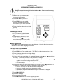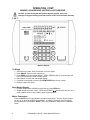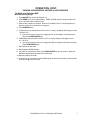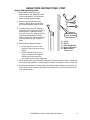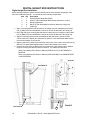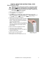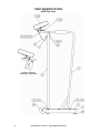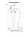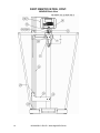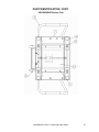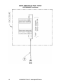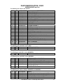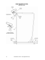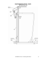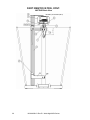
1
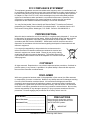
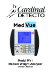
Waist-High Digital Bariatric Scale Model 685X Series Operating Instructions 1930-M458-O1 Rev E 10/14 CARDINAL SCALE MFG. CO. PO BOX 151 WEBB CITY, MO 64870 PH (417) 673-4631 FAX (417) 673-5001 www.detectoscale.com Technical Support: Ph: 866-254-8261 [email protected] Printed in USA FCC COMPLIANCE STATEMENT This equipment generates uses and can radiate radio frequency and if not installed and used in accordance with the instruction manual, may cause interference to radio communications. It has been tested and found to comply with the limits for a Class A computing device pursuant to Subpart J of Part 15 of FCC rules, which are designed to provide reasonable protection against such interference when operated in a commercial environment. Operation of this equipment in a residential area may cause interference in which case the user will be responsible to take whatever measures necessary to correct the interference. You may find the booklet "How to Identify and Resolve Radio TV Interference Problems" prepared by the Federal Communications Commission helpful. It is available from the U.S. Government Printing Office, Washington, D.C. 20402. Stock No. 001-000-00315-4. PROPER DISPOSAL When this device reaches the end of its useful life, it must be properly disposed of. It must not be disposed of as unsorted municipal waste. Within the European Union, this device should be returned to the distributor from where it was purchased for proper disposal. This is in accordance with EU Directive 2002/96/EC. Within North America, the device should be disposed of in accordance with the local laws regarding the disposal of waste electrical and electronic equipment. It is everyone’s responsibility to help maintain the environment and to reduce the effects of hazardous substances contained in electrical and electronic equipment on human health. Please do your part by making certain that this device is properly disposed of. The symbol shown to the right indicates that this device must not be disposed of in unsorted municipal waste programs. COPYRIGHT All rights reserved. Reproduction or use, without expressed written permission, of editorial or pictorial content, in any manner, is prohibited. No patent liability is assumed with respect to the use of the information contained herein. DISCLAIMER While every precaution has been taken in the preparation of this manual, the Seller assumes no responsibility for errors or omissions. Neither is any liability assumed for damages resulting from use of the information contained herein. All instructions and diagrams have been checked for accuracy and ease of application; however, success and safety in working with tools depend to a great extent upon the individual accuracy, skill and caution. For this reason the Seller is not able to guarantee the result of any procedure contained herein. Nor can they assume responsibility for any damage to property or injury to persons occasioned from the procedures. Persons engaging the procedures do so entirely at their own risk. Serial Number_______________________ Date of Purchase ____________________ Purchased Form_____________________ PRECAUTIONS Before using this instrument, read this manual and pay special attention to all "NOTIFICATION" symbols: ___________________________________ ___________________________________ IMPORTANT RETAIN THIS INFORMATION FOR FUTURE USE 1930-M458-O1 Rev-E Waist-High 685X Series 1 2 6855 / 6855KGEU 6856 / 6856KGEU 6854DHR / 6854KGEUDHR 6857DHR / 6857KGEUDHR 1930-M458-O1 Rev-E Waist-High 685X Series INTRODUCTION Thank you for purchasing our Waist-High Digital Bariatric Scale. It has been manufactured with quality and reliability at our factory in Webb City, MO USA. Your scale has been tested before leaving our factory to insure accuracy and dependability for years to come. This manual is provided to guide you through the operation of your scale. Please read it thoroughly before attempting to operate your scale and keep it handy for future reference. SPECIFICATIONS 6855 6855KGEU 6856 6856KGEU 300 kg x 0.1 kg or 350 kg x 0.2 kg Capacity: 600 lb x .2 lb or 300 kg x 0.1 kg 270 kg x .1 kg or (selectable) 350 kg x 0.2 kg 1000 lb x .2 lb or 450 kg x .1 kg (selectable) Platform Size: 18” x 14” / 46 cm x 36 cm 24” x 24” / 61 cm x 61 cm Shipping Weight: 70 lb / 32 kg 85 lb / 39 kg Height Rod: 30” to 78” x 0.1 in (76 cm to 200 cm x 0.1 cm) Display: Six digit, Seven segment, 0.7 inch (17.8 mm) high LCD Power: 6 “AA” size Alkaline, Ni-Cad or NiMH batteries (not included) OR an optional 100 to 240 VAC 50/60Hz 12 VDC 1A wall plug-in UL/CSA listed AC power supply (Cardinal part number 6800-1045). Keyboard: Membrane type with 5 keys, On/Off, Lock/Release, Units, Zero, BMI/Enter and 4 directional arrows 6854DHR 6854KGEUDHR 6857DHR 6857KGEUDHR Capacity: 600 lb x .2 lb or 300 kg x 0.1 kg 270 kg x .1 kg or (selectable) 350 kg x 0.2 kg 1000 lb x .2 lb or 300 kg x 0.1 kg 360 kg x .1 kg or (selectable) 350 kg x 0.2 kg Platform Size: 18” x 14” / 46 cm x 36 cm 24” x 24” / 61 cm x 61 cm Shipping Weight: 74 lb / 34 kg 85 lb / 39 kg Digital Height Rod: 43” to 79” x 0.1 in (110 cm to 200 cm x 0.1 cm) Display: Weight: 5 digit, seven segment, 7/8” (22.23 mm) high LCD Height: 4 digit, seven segment, 1/2" (12.7 mm) high LCD BMI: 3 digit, seven segment, 1/2" (12.7 mm) high LCD ID: 14 digit, 14 segment, .35” (8.89 mm) high LCD Power: 6854DHR / 6857DHR: 6 “C” cell Alkaline, Ni-Cad or NiMH batteries (not included) OR an optional 12 VDC 1.25A wall plug-in AC power adapter (Cardinal part number MV1PWR). 6854KGEUDHR / 6857KGEUDHR: 6 “C” cell Ni-Cad or NiMH batteries (not included) OR an optional 12 VDC 1.25A wall plug-in AC power adapter (Cardinal part number MV2PWR). Keys: Membrane type with 19 keys, On/Off, Zero, Units, Lock/Release, Net/Gross, Tare, ID/Height, Clear, Print/Enter and 0-9 Numeric Keys 1930-M458-O1 Rev-E Waist-High 685X Series 3 UNPACKING INSTRUCTIONS Remove staples or cut along bottom of carton. Lift carton off pallet. Check for any damage incurred in shipping. If scale has been damaged, place a claim with the carrier. It is the responsibility of the purchaser to file all claims for any damages or loss incurred during transit. Use the original carton and shipping material to return the scale. Cut packing straps securing scale to pallet. To remove scale from pallet, at the back of the scale lift up with equal force from the column and at the platform base near the wheels on the scale. Set gently on floor. Remove all plastic wrapping, foam fillers and cardboard material from the scale. Remove and unpack the power supply and cord, if the scale was ordered with this option. Install the batteries or if ordered with the scale, plug the small connector end of the power supply cord into the power jack located on the back of the indicator, then plug the power supply module into an appropriate power receptacle. NOTE! DO NOT connect a power supply to the indicator if Alkaline batteries are installed. Install the indicator on the scale bracket on the column and then connect the load cell cable to the indicator. NOTE: For additional information on installing the batteries (or the power supply module), mounting the indicator on the scale bracket and connecting the load cell cable; Refer to the 750 Weight Indicator Owner’s Manual (8555-M483-O1) for the 6855, 6855KGEU, 6856 or 6856KGEU Refer to the MedVue MV1 Owner’s Manual (8555-M512-O1) for the 6854DHR or 6857DHR. Refer to the MedVue MV2 Owner’s Manual (8555-0530-0M) for the 6854KGEUDHR or 6857KGEUDHR CARE AND CLEANING OF SCALE 4 DO NOT subject the platform to sudden shocks. DO NOT submerge indicator in water, pour or spray water directly on indicator. DO NOT use acetone, thinner or other volatile solvents for cleaning. DO NOT expose scale to temperature extremes. DO NOT place scale in front of heating/cooling vents. DO NOT place scale in an area where it might be exposed to moisture. DO clean the indicator with a damp soft cloth and mild non-abrasive detergent. DO remove power before cleaning with a damp cloth. DO provide clean AC power and adequate protection against lightning damage. DO keep the surroundings clear to provide clean and adequate air circulation. 1930-M458-O1 Rev-E Waist-High 685X Series OPERATION 6855, 6855KGEU, 6856 or 6856KGEU DO NOT operate the keypad with pointed objects (pencils, pens, etc). Damage to keypad resulting from this practice is NOT covered under warranty. To Weigh 1. Set scale on any hard, level, flat surface or low-cut carpet. 2. Press ON / OFF key to turn on indicator. 3. Press ZERO key to zero weight display. The ZERO and lb or kg annunciator will turn on to show that scale is ready for use. 4. Place patient on scale and read weight display. 5. Remove patient from scale. Zero Weight Display 1. If the indicator is not showing zero weight on the display, press ZERO key. 2. Weight display will return to zero. ZERO, STABLE and lb or kg annunciators will turn on to show a stable, center-of-zero weight condition. 750 Keypad Metric Conversion Press UNITS key to toggle between pounds and kilograms. Note that lb or kg annunciator will turn on to show which weighing unit is active. To Weigh and Calculate BMI 1. Press ON / OFF key to turn on indicator. 2. Press ZERO key to zero weight display. The ZERO and lb or kg annunciator will turn on to show that scale is ready for use. 3. Place patient on scale and read weight display. 4. Press BMI / ENTER key. 5. If pounds is the active weighing unit, display will change to show 5 FEET, 6 INCHES with the 6 blinking. (The blinking character is the position to be changed). a. Press or keys until desired height in inches is displayed and then press or key to move the blinking character to FEET. b. Press or keys until desired height in feet is displayed. c. Proceed to Step 7. 6. If kilograms is the active weighing unit, display will change to show 170 cm.with the 0 of 170 blinking. (The blinking character is the position to be changed)... a. Press or keys until the desired number is displayed. b. Press or key to move to next character to change. c. Repeat steps A and B until the desired height in centimeters is displayed. d. Proceed to Step 7. 7. Press BMI / ENTER key. 8. Read BMI on display. 9. Remove patient from scale. 10. Press BMI / ENTER key to return to weighing operation. 1930-M458-O1 Rev-E Waist-High 685X Series 5 OPERATION, CONT. 6854DHR, 6854KGEUDHR, 6857DHR or 6857KGEUDHR DO NOT operate the keypad with pointed objects (pencils, pens, etc). Damage to keypad resulting from this practice is NOT covered under warranty. MedVue Keypad To Weigh 1. Set scale on any hard, level, flat surface or low-cut carpet. 2. Press ON/OFF key to turn the indicator on. 3. Press ZERO key to zero weight display. ZERO, GROSS and lb or kg annunciator will turn on to show that the scale is ready for use. 4. Place patient on scale and read weight display. 5. If a printer is connected to scale, press PRINT/ENTER key to print a ticket. 6. Remove patient from scale. Zero Weight Display 1. In Gross Weight mode (GROSS annunciator on), press ZERO key. 2. Weight display will return to zero. ZERO and STABLE annunciators will turn on to show a stable, center-of-zero (0) gross weight condition. Metric Conversion Press the UNITS key to toggle between pounds and kilograms. The lb or kg annunciator will turn on to show the weighing unit selected. In addition, the height units will change from feet/inches to centimeters. NOTE: This is only available if configured in Calibration Setup. 6 1930-M458-O1 Rev-E Waist-High 685X Series OPERATION, CONT. 6854DHR, 6854KGEUDHR, 6857DHR or 6857KGEUDHR To Weigh and Calculate BMI Manually Entering Height 1. Press ON/OFF key to turn the indicator on. 2. Press ZERO key to zero weight display. ZERO, GROSS and lb or kg annunciator will turn on to show scale is ready for use. 3. Perform tare operation if required. Refer to Push Button Tare or Tare Weight Entry in previous section for instructions on using tare. 4. Press ID/HEIGHT key. 5. If Centimeters was selected for HEIGHT UNITS in setup, the display will change to show CENTIMETERS. a. Use numeric keys to enter up to 4 digits (# # # . #) for height in centimeters and then press PRINT/ENTER key. 6. If Millimeters was selected for HEIGHT UNITS in setup, display will change to show MILLIMETERS. a. Use numeric keys to enter up to 4 digits (# # # #) for height in millimeters and then press PRINT/ENTER key. 7. Place patient on the scale. 8. Read weight and BMI displays. 9. If a printer is connected to scale, press PRINT/ENTER key to print a ticket. Note that BMI and height display will clear when ticket prints. 10. Remove patient from scale. 11. If a printer is not connected to scale, BMI display will clear when patient is removed from scale and weight returns to zero. 1930-M458-O1 Rev-E Waist-High 685X Series 7 HEIGHT ROD INSTRUCTIONS Height Rod Hole Location Please check Height Rod hole locations before installing Height Rod. Some models may require holes to be drilled. Please follow the measurements for drilling holes if necessary. After holes have been drilled, please follow installation instructions. Install the two (2) #10 x ½” hex head screws from the hardware pack into the column. 28 IMPORTANT! Measure from top of scale base. 13/16 4 5/16 Height Rod Installation 1. Remove Height Rod from shipping container. Inspect the unit for signs of damage. Contact our Customer Service Department if necessary. 2. Loosen screws located on front of scale column. Place height rod brackets over screws and pull down; securing brackets. Tighten screws as needed. NOTE: The Indicator must be facing away from the scale platform to install the height rod. 8 1930-M458-O1 Rev-E Waist-High 685X Series #29 (.136) diameter holes, 1” from edge of column to center of hole HEIGHT ROD INSTRUCTIONS, CONT. Height Rod Operating Guide 1. Before patient steps onto scale platform, spoon (B) should be rotated to horizontal position, and raised well above patient's apparent height. 2. Patient may now step onto scale platform. Spoon (B) should be held horizontal and above patient's head. A B C E 3. Carefully lower spoon (B), keeping it horizontal, until it rests gently on top of patient's head. If patient is shorter than 3' 4" (101.5 cm), push latch (A) to right while simultaneously pushing down on spoon (B), until the spoon (B) rests horizontally on top of patient's head. 4. Read height of patient as follows: If back of spoon points to outer height rod, then it points to correct height. If back of spoon points to inner height rod, then correct height is read at top of outer height rod (see "Read" arrow on outer height rod). D Height Rod in “rest” position A = Latch B = Spoon C = Inner Height Rod D = Outer Height Rod E = Measurement “Read” Line 5. While holding spoon (B) horizontally, raise spoon (B) above patient's head. Patient may now step off scale platform. Hold spoon (B) horizontal until patient is clear of height rod. 6. Rotate spoon (B) back to vertical position and adjust height rod back to rest position (i.e. spoon (B) should be locked in place within inner height rod (C) and inner rod should be at its lowest position). 1930-M458-O1 Rev-E Waist-High 685X Series 9 DIGITAL HEIGHT ROD INSTRUCTIONS Digital Height Rod Installation Before starting installation, please unpack carefully and remove all plastic wrappings, foam fillers and cardboard material. You should have the following components: Item Qty 1 1 2 4 3 2 4 8 5 3 Description Detecto Digital Height Rod (DHR) #10x1/2” Hex Head Sheet Metal Screws (bracket to column) Mounting Brackets M4x0.7x5 Pan Head Machine Screws (bracket to height rod) Cable Clip 1. Align a mounting bracket with the holes in the height rod (near headpiece) and install four (4) M4x0.7x4 Pan Head Machine screws to secure the bracket to the height rod. 2. Next, align the other mounting bracket with the lower holes in the height rod and install four (4) M4x0.7x4 Pan Head Machine screws to secure the bracket to the height rod. 3. Align the mounting bracket (near the headpiece) with the holes in the back of the column close to the display and install two (2) #10x1/2” Hex Head Sheet Metal screws to secure the bracket to the column. 4. Align the holes in the other bracket with the lower holes in the column and install two (2) #10x1/2” Hex Head Sheet Metal screws to secure the bracket to the column. 5. Connect the cable from the DHR to the port on the rear of the indicator that is labeled height rod routing the cable as shown in Detail B. For additional information; Refer to the MedVue MV1 Owner’s Manual (8555-M512-O1) for the 6854DHR or 6857DHR. Refer to the MedVue MV2 Owner’s Manual (8555-0530-0M) for the 6854KGEUDHR or 6857KGEUDHR 1 Column See Detail B 4 2 3 Detail A See Detail A 10 Detail B 5 1930-M458-O1 Rev-E Waist-High 685X Series DIGITAL HEIGHT ROD INSTRUCTIONS, CONT. Measuring Patient’s Height IMPORTANT! Before performing the operations on this page, the digital height rod must be in its “starting position” (inner sliding tube must be down completely inside outer stationary tube and headpiece folded flat against stationary tube) prior to turning on the indicator. Otherwise, the error message 999.9 will be displayed. 1. Make sure height rod is in starting position. 2. Press ON/OFF key to turn indicator on. 3. Press ZERO key to zero weight display. ZERO, GROSS and lb, oz, kg or ST annunciator will turn on to show scale is ready for use. Note that height reading will show 3-&3 FT-INCHES or 110.0 cm (depending on Unit= setting in Setup). 4. Patient may now step onto scale platform. 5. Grasp height rod at hinge pin and raise it well above patient’s head and then lift headpiece to horizontal position. Carefully lower height rod until headpiece rests on top of patient’s head. NOTE: If the patient is under 3 ft, 7.3 in (110 cm) or over 6 ft, 7.1 in (201 cm) return the digital height rod to the “starting position” and manually enter the patient’s height. 6. BMI will automatically be displayed with height. 7. Read weight, height and BMI displays. 8. While holding headpiece horizontal, raise height rod well above patient’s head. 9. Patient may now step off scale platform. 10. Return height rod to starting position. Grasp at Hinge Pin 11. BMI display will clear when weight returns to zero. 1930-M458-O1 Rev-E Waist-High 685X Series 11 PART IDENTIFICATION 6855 Side View Indicator Alternate Mounting Configuration 12 1930-M458-O1 Rev-E Waist-High 685X Series PART IDENTIFICATION, CONT. 6854DHR Side View 1930-M458-O1 Rev-E Waist-High 685X Series 13 PART IDENTIFICATION, CONT. 6854DHR Back View 14 1930-M458-O1 Rev-E Waist-High 685X Series PART IDENTIFICATION, CONT. 6855/6854DHR Bottom View 1930-M458-O1 Rev-E Waist-High 685X Series 15 PART IDENTIFICATION, CONT. 6855/6854DHR Trim Board 16 1930-M458-O1 Rev-E Waist-High 685X Series PART IDENTIFICATION, CONT. 6855/6854DHR Parts List The following are used on ALL models: ITEM # QTY PART NUMBER 1 1 1930-D330-0A 2 1 1930-C338-08 3 6 6007-0034 4 6 6024-0050 5 6 6013-0275 6 1 1930-C143-0A 9 4 6021-0665 10 1 391RV204 11 1 6680-1043 12 1 1930-B336-1A 13 1 1930-C337-08 14 1 6024-0047 15 1 6021-1423 16 1 0033-B110-08 17 1 6024-0004 18 1 1930-B428-0A 19 1 6021-1454 20 1 0033-C090-0A 21 2 6013-0045 29 1 6650-0087 36 4 0065-B108-08 37 4 LFB-250M DESCRIPTION WEIGHBRIDGE ASSY MAT W/ADHESIVE HEX HEAD SCREW 5/16-18 UNC-2A X 3/4” LOCK WASHER 5/16” HEX NUT 5/16-18 UNC-2B HANDRAIL ASSEMBLY MACHINE SCREW #6-32 X .375 PAN HD PHILLIP DR ELASTIC STOP NUT GROMMET COLUMN ASSEMBLY COVER EXT STAR WASHER 1/4” TRUSS HEAD SCREW 1/4-20 UNC-2A X 1/2” UHMW DISK FLAT WASHER 1/4” DIA SS CABLE HEX HEAD BOLT 1/4-20 UNC-2A X 3/4” WHEEL ASSY. HEX NUT 1/4-20 UNC LABEL, MADE IN USA (WITH FLAG) FOOT, ALUMINUM LOAD CELL, SHEAR BEAM, 125 KG, SS The following are used ONLY on the 6855: 7 8 REF 750 1 0033-B438-OA DIGITAL INDICATOR MTG BRKT ASSY – 750 The following is used ONLY on the 6855KGEU: 22 REF MV2 DIGITAL INDICATOR The following are used ONLY on the 6854DHR: 24 25 26 27 28 1 2 4 REF 8 30 3 DHR 1930-C475-08 6021-1629 MV1 6021-1556 6610-5007 DETECTO DIGITAL HEIGHT ROD DHR BRACKET SCW HX-HD. COMBO SHEET-METAL #10 X 3/4 WEIGHT INDICATOR FOR CLINICAL SCALES SCW PAN-HEAR MACHINE-SCW M4X0.7X5, PHILLIPS DRIVE, Z/P CABLE CLIP, 1” X 1” GREY The following are used on both the 6855KGEU and 6854DHR: 31 32 33 34 35 2 1 1 1 1 8555-C508-08 6540-1053 6680-0250 6024-1066 6021-0950 MOUNT ENCLOSURE KNOB 1.25 DIA, 10-32 INSERT SPACER, NYLON .26 ID X .50 OD X .187 LG FLAT WASHER 1/4 X 1 X1 1/16 THK Z/P SCW HEX-HEAD 10-32 X 1.50 Z/P 1930-M458-O1 Rev-E Waist-High 685X Series 17 PART IDENTIFICATION 6856 Side View Indicator Alternate Mounting Configuration 18 1930-M458-O1 Rev-E Waist-High 685X Series PART IDENTIFICATION, CONT. 6857DHR Side View 1930-M458-O1 Rev-E Waist-High 685X Series 19 PART IDENTIFICATION, CONT. 6857DHR Back View 20 1930-M458-O1 Rev-E Waist-High 685X Series PART IDENTIFICATION, CONT. 6856/6857DHR Bottom View 1930-M458-O1 Rev-E Waist-High 685X Series 21 PART IDENTIFICATION, CONT. 6856/6857DHR Trim Board 22 1930-M458-O1 Rev-E Waist-High 685X Series PART IDENTIFICATION, CONT. 6856/6857DHR Parts List The following are used on ALL models: ITEM # QTY PART NUMBER 1 1 1930-D445-0A 2 1 1930-C452-08 3 6 6007-0034 4 6 6024-0050 5 6 6013-0275 6 1 1930-C450-0A 9 4 6021-0665 10 1 391RV204 11 1 6680-1043 12 1 1930-B336-1A 13 1 1930-C451-08 14 1 6024-0047 15 1 6021-2037 16 1 0033-B110-08 17 1 6024-0004 18 1 1930-B428-0A 19 1 6021-1454 20 1 0033-C090-0A 21 2 6013-0045 29 REF 5930-B137-08 37 4 0065-B108-08 38 4 LFB-250M DESCRIPTION WEIGHBRIDGE ASSY MAT W/ADHESIVE HEX HEAD SCREW 5/16-18 UNC-2A X 3/4” LOCK WASHER 5/16” HEX NUT 5/16-18 UNC-2B HANDRAIL ASSEMBLY MACHINE SCREW #6-32 X .375 PAN HD PHILLIP DR ELASTIC STOP NUT GROMMET COLUMN ASSEMBLY COVER EXT STAR WASHER 1/4” BINDING HD SCW .25-20 X .50 UHMW DISK FLAT WASHER 1/4” DIA SS CABLE HEX HEAD BOLT 1/4-20 UNC-2A X 3/4” WHEEL ASSY. HEX NUT 1/4-20 UNC LABEL FOOT, ALUMINUM LOAD CELL, SHEAR BEAM, 125 KG, SS The following are used ONLY on the 6856: 7 8 REF 750 1 0033-B438-OA DIGITAL INDICATOR MTG BRKT ASSY – 750 The following is used ONLY on the 6856KGEU: 22 REF MV2 DIGITAL INDICATOR The following are used ONLY on the 6857DHR: 24 25 26 27 28 1 2 4 REF 8 30 3 DHR 1930-C475-08 6021-1629 MV1 6021-1556 6610-5007 DETECTO DIGITAL HEIGHT ROD DHR BRACKET SCW HX-HD. COMBO SHEET-METAL #10 X 3/4 WEIGHT INDICATOR FOR CLINICAL SCALES SCW PAN-HEAR MACHINE-SCW M4X0.7X5, PHILLIPS DRIVE, Z/P CABLE CLIP, 1” X 1” GREY The following are used on both the 6856KGEU and 6857DHR: 31 32 33 34 35 36 REF 2 1 1 1 1 593GR986 8555-C508-08 6540-1053 6680-0250 6024-1066 6021-0950 SERIAL TAG MOUNT ENCLOSURE KNOB 1.25 DIA, 10-32 INSERT SPACER, NYLON .26 ID X .50 OD X .187 LG FLAT WASHER 1/4 X 1 X1 1/16 THK Z/P SCW HEX-HEAD 10-32 X 1.50 Z/P 1930-M458-O1 Rev-E Waist-High 685X Series 23 STATEMENT OF LIMITED WARRANTY Detecto Scale warrants its equipment to be free from defects in material and workmanship as follows: Detecto warrants to the original purchaser only that it will repair or replace any part of equipment which is defective in material or workmanship for a period of two (2) years from date of shipment. Detecto shall be the sole judge of what constitutes a defect. During the first ninety (90) days Detecto may choose to replace the product at no charge to the buyer upon inspection of the returned item. After the first ninety (90) days, upon inspection of the returned item, Detecto will repair or replace it with a remanufactured product. The customer is responsible for paying for the freight both ways. This warranty does not apply to peripheral equipment not manufactured by Detecto; this equipment will be covered by certain manufacturer’s warranty only. This warranty does not include replacement of expendable or consumable parts. This does not apply to any item which has deteriorated or damaged due to wear, accident, misuse, abuse, improper line voltage, overloading, theft, lightning, fire, water or acts of God, or due to extended storage or exposure while in purchaser’s possession. This warranty does not apply to maintenance service. Purchased parts will have a ninety (90) day repair or replacement warranty only. Detecto may require the suspect product to be returned to the factory; item(s) must be properly packed and shipping charges prepaid. A return authorization number must be obtained for all returns and marked on the outside of all returned packages. Detecto accepts no responsibility for loss or damage in transit. 24 1930-M458-O1 Rev-E Waist-High 685X Series STATEMENT OF LIMITED WARRANTY Conditions Which Void Limited Warranty This warranty shall not apply to equipment which: A.) Has been tampered with, defaced, mishandled or has had repairs and modifications not authorized by Detecto. B.) Has had serial number altered, defaced, or removed. C.) Has not been grounded according to Detecto’s recommended procedure. Freight Carrier Damage Claims for equipment damaged in transit must be referred to the freight carrier in accordance with freight carrier regulations. This warranty sets forth the extent of our liability for breach of any warranty or deficiency in connection with the sale or use of the product. Detecto will not be liable for consequential damages of any nature, including but not limited to, loss of profit, delays or expenses, whether based on tort or contract. Detecto reserves the right to incorporate improvements in material and design without notice and is not obligated to incorporate improvements in equipment previously manufactured. The foregoing is in lieu of all other warranties, express or implied including any warranty that extends beyond the description of the product including any warranty of merchantability or fitness for a particular purpose. This warranty covers only those Detecto products installed in the forty-eight (48) contiguous continental United States. Ph. (800) 641-2008 E-mail: [email protected] 203 E. Daugherty Webb City, MO 64870 1930-M458-O1 Rev-E Waist-High 685X Series 08/27/2014 Printed in USA D268-WARRANTY-DET-A 25 26 1930-M458-O1 Rev-E Waist-High 685X Series