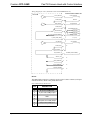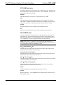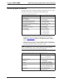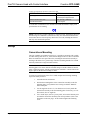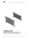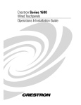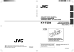
1
Crestron CPC-CAMI Pan/Tilt Camera Head with Control Interface Contents Pan/Tilt Camera Head with Control Interface: CPC-CAMI 1 Description................................................................................................................................. 1 Functional Description ................................................................................................ 1 Physical Description.................................................................................................... 2 Leading Specifications............................................................................................................... 7 Setup .......................................................................................................................................... 8 Camera/Lens Mounting ............................................................................................... 8 Identity Code ............................................................................................................. 10 Preparation for Use.................................................................................................... 11 Initialization............................................................................................................... 11 Limit Stop Adjustment .............................................................................................. 12 Calibration ................................................................................................................. 12 Maintenance .............................................................................................................. 13 Programming ........................................................................................................................... 13 Position/Rate Mode Definition.................................................................................. 13 Programming the CPC-CAMI in SIMPL .................................................................. 13 Problem Solving ...................................................................................................................... 17 Troubleshooting ........................................................................................................ 17 Further Inquiries........................................................................................................ 17 Return and Warranty Policies.................................................................................................. 18 Merchandise Returns / Repair Service ...................................................................... 18 CRESTRON Limited Warranty ................................................................................ 18 Appendix: Application Examples............................................................................................ 19 Lens Cabling Connection for Jumper A (+/-12V)..................................................... 19 Lens Cabling Connection for Jumper B (+/-8V)....................................................... 20 Lens Cabling Connection for Jumper D (+/-6V)....................................................... 20 Lens Cabling Connection for Jumper C (+2.5V to +7.5V) ....................................... 20 Operations Guide - DOC. 5726A Contents • i Crestron CPC-CAMI Pan/Tilt Camera Head with Control Interface Pan/Tilt Camera Head with Control Interface: CPC-CAMI Description Functional Description The CPC-CAMI is an integrated pan/tilt head and network control interface belonging to the Crestron ProCam family of network camera control. The unit has been designed to provide control of a remotely positioned video camera site. Control is defined as the two-axis motion of the pan/tilt unit and the focus/zoom setting of a camera lens. The CPC-CAMI provides exclusive SpeedSmart™ technology to assure the fastest yet smoothest - camera response possible. Pulse width modulation insures high speed resolution and the unit possesses a remarkable ability to repeat preset positions. When connected to a Crestron control system, the unit’s “whisper-quiet” movement of a camera/lens assembly is controlled by its own built-in network control interface. Jumper Boards Four supplied jumper boards permit the support of any camera/lens assembly requiring an input voltage in the range of +/-2.5 to +/- 12 VDC. Thus a single CPC-CAMI with its four jumpers can control nearly any camera/lens in the industry. Refer to the table below for exact voltage outputs for each jumper board. NOTE: If no jumper board is connected to the CPC-CAMI, the lens outputs are disconnected. Jumper Board Options JUMPER BOARD VOLTAGE CONFIGURATIONS LENS A +/- 12 VDC differential drive LENS B +/- 8 VDC differential drive +/- 2.5 VDC single ended drive with lens supplied reference (implements 2.5V to 7.5V with lens supplied center (5V)) +/- 6 VDC differential drive LENS C LENS D Operations Guide - DOC. 5726A LENSES CONTROLLED Panasonic WV-LZ81/10, Canon J6x11 REA-IA-II, Daiwa/CSI, and Cosmicar H6ZAHE-2P and C6Z1218H2ESP-2 H1020812 AMSP, Daiwa/CSI, and Computar H10Z0812M Fujinon MD, BMD and SD series, JVC HZ-713MD, Daiwa/CSI, and Canon KTS/KTS-A series Daiwa/CSI and Vicon M & MS series Pan/Tilt Camera Head with Control Interface: CPC-CAMI • 1 Pan/Tilt Camera Head with Control Interface Crestron CPC-CAMI Presets In conjunction with the Crestron control system, the CPC-CAMI is capable of “memorizing” pan/tilt positions and focus/zoom settings for a virtually unlimited number of presets. Each preset stores a specific position and setting. Positional feedback signals are essential to the implementation of presets; unless the lens supports position mode. These analog signals, provided by the pan/tilt and lens, indicate current pan/tilt position and focus/zoom setting. Position/Rate Mode Movement of the camera lens may occur in either position or rate mode. A jumper board may be selected that best accommodates the mode parameters required by the system. Refer to “Position/Rate Mode Definition” on page 13 for a more detailed explanation of position and rate mode. Physical Description The CPC-CAMI, shown below, is housed in a black enclosure with two rotating disks for the pan and tilt axes. A stop sensor is located on each side of the unit having a rotating disk. Each disk has two adjustable locking screws. The disks also feature heavy duty precision bearings for long life and minimal friction. The interface box is affixed onto the sloping portion of the pan/tilt head. All electrical connections are made to the interface box; refer to the silk-screened labels. CPC-CAMI Physical Views 2 • Pan/Tilt Camera Head with Control Interface: CPC-CAMI Operations Guide - DOC. 5726A Crestron CPC-CAMI Pan/Tilt Camera Head with Control Interface Adjustable mounting plates (flat and angled) and mounting hardware are provided with each CPC-CAMI. The two plates can be fixed to one of the rotating disks with the mounting hardware to provide camera/lens support. The other disk serves as a mounting platform for the CPC-CAMI with attached camera/lens assembly. CPC-CAMI Ports A number of ports are located on the CPC-CAMI interface box. Each has a silkscreened label. Refer to the illustration and descriptions after this paragraph. CPC-CAMI Inteface Box NET This 6-pin, 6-position RJ11 modular jack is used to connect the CPC-CAMI to the control system. NOTE: Before making connections to the NET port, review the latest revision of the Network Modular Cable Requirements (Doc. 5682). Most 4-conductor phone cables are wired in a crisscross fashion and are not compatible with Crestron equipment. The wiring document can be obtained from the Downloads page (CABLES and MANUALS Libraries) of the Crestron website (www.crestron.com). Search for the MODULAR.PDF file. LENS This DB15 female connector provides three channels for zoom, focus, and iris, as well as additional signals depending on lens. Refer to the pinout table below. A 15pin D-sub male connector with hood (P/N 748048-1) is supplied and attaches to the LENS port. To properly wire this male connector, a wiring schematic for each lens type (A through D) follows the pinout table. Crestron maintains a limited number of cabling drawings for lenses. Refer to “Appendix: Application Examples” on page 19 for specific pan/tilt and lens applications. The information in the appendix offers recommended cabling connections with the appropriate lens type. Operations Guide - DOC. 5726A Pan/Tilt Camera Head with Control Interface: CPC-CAMI • 3 Pan/Tilt Camera Head with Control Interface Crestron CPC-CAMI CPC-CAMI Pinout for LENS Port PIN DESCRIPTION 1 2 3 4 5 6 7 8 9 10 11 12 13 14 15 Focus Out Focus Common Zoom Out Zoom Common Rate/Position Mode 5V Reference from Lens 7.5V Reference from Lens Iris Out Iris Common Iris Control 1 Iris Control 2 +5V to Pots Pot Zoom Pot Focus 0 Volts to Pots Wiring Diagram for Lens A, B, and D (+/-12V, +/-8V, and +/-6V) CPC-CAMI FOCUS_MOTOR 1 M POWER_GND ZOOM_MOTOR 2 3 M POWER_GND RATE/POSITION +5V_VOLTS_LENSE_REFERENCE 7_VOLTS_FROM_LENSE IRIS_MOTOR 4 5 n/c 6 n/c 7 n/c 8 M POWER_GND IRIS_CONTROL_1 IRIS_CONTROL_2 FEEDBACK_SUPPLY_+5V ZOOM_FEEDBACK FOCUS_FEEDBACK FEEDBACK_GROUND 4 • Pan/Tilt Camera Head with Control Interface: CPC-CAMI 9 10 n/c 11 n/c 12 13 14 15 Operations Guide - DOC. 5726A Crestron CPC-CAMI Pan/Tilt Camera Head with Control Interface Wiring Diagram for Lens C (KTS/KTS-A Series and MD/BMD/SD Series) HIROSE LENSE CONNECTOR CPC-CAMI FOCUS_MOTOR POWER_GND ZOOM_MOTOR POWER_GND FOCUS CONTROL 1 GROUND 2 ZOOM CONTROL 3 FOCUS SPEED/POS SIG 5 IRIS SPEED/POS SIG +5V_VOLTS_LENSE_REFERENCE 7_VOLTS_FROM_LENSE IRIS_MOTOR POWER_GND IRIS_CONTROL_1 IRIS_CONTROL_2 ANALOG_+5V ZOOM_FEEDBACK FOCUS_FEEDBACK ANALOG_GROUND 3 9 4 ZOOM SPEED/POS SIG RATE/POSITION 8 SIGNAL COMMON 6 +V1 (+7.5V) 7 IRIS_CONTROL 8 9 2 1 10 7 11 5 n/c 10 11 IRIS MODE (LOCAL/CAMERA) 12 n/c 13 n/c 14 n/c 15 n/c 4 RS-232 This DB9 female connector is primarily used to control “smart” cameras (serial-portcontrolled cameras). Refer to the pinout table below. CPC-CAMI Pinout for RS-232 Port Operations Guide - DOC. 5726A PIN DESCRIPTION 1 2 3 4 5 6 7 8 9 Rx (to CPC-CAMI) Input Tx (from CPC-CAMI) Output GND RTS (from CPC-CAMI) Output CTS (to CPC-CAMI) Input - Pan/Tilt Camera Head with Control Interface: CPC-CAMI • 5 Pan/Tilt Camera Head with Control Interface Crestron CPC-CAMI CPC-CAMI Indicators A number of indicators are located on the CPC-CAMI interface box. Each has a silkscreened label. Refer to the illustration shown in “CPC-CAMI Ports” on page 3 and the descriptions after this paragraph. POWER This LED illuminates when 24 VDC is supplied to the CPC-CAMI. NET This LED illuminates when communication between the control system and the CPC-CAMI is established. Illumination indicates that the SIMPL program currently loaded has a network device defined at the same NET ID as the CPC-CAMI. CALIB Flashing LED indicates CPC-CAMI has entered calibration mode. FZ Indicates focus and zoom activity as the result of manual control at the unit. CPC-CAMI Buttons A number of buttons are located on the CPC-CAMI interface box. The purpose of these buttons is to permit local manual operation of motor control functions when installing the unit. Each has a silk-screened label. Refer to the illustration shown in “CPC-CAMI Ports” on page 3 and the descriptions after this paragraph. NOTE: Each set of up (∧) and down (∨) buttons provides dual function. For example, the upper-most up/down button provides either pan movement of the head or focus adjustment of the lense depending on mode. PAN ∧ (LEFT)/FOCUS ∧ (IN) This button provides either manual pan leftward movement of the camera head or manual focus inward control of the camera lens. PAN ∨ (RIGHT)/FOCUS ∨ (OUT) This button provides either manual pan rightward movement of the camera head or manual focus outward control of the camera lens. TILT ∧ (UP)/ZOOM ∧ (IN) This button provides either manual tilt upward control of the camera head or manual zoom inward control of the camera lens. TILT ∨ (DOWN)/ZOOM ∨ (OUT) This button provides either manual tilt downward control of the camera head or manual zoom outward control of the camera lens. MODE This button toggles between pan/tilt and zoom/focus movement. CALIB Depressing the TILT ∧ (UP) and MODE buttons simultaneously enables the unit to enter calibration mode. 6 • Pan/Tilt Camera Head with Control Interface: CPC-CAMI Operations Guide - DOC. 5726A Crestron CPC-CAMI Pan/Tilt Camera Head with Control Interface Leading Specifications The table below provides a summary of leading specifications for the CPC-CAMI. Dimensions and weights are rounded to the nearest hundredth unit. Leading Specifications of the CPC-CAMI SPECIFICATION DETAILS Power Requirements 24 VDC, 2.5A; 60 Watts Default Network ID 34 SIMPL™ Windows® Version 1.18 or later CNMSX-AV/PRO Upgrade File (.upz) Version 5.01.35x or later CNRACKX/-DP Upgrade File (.upz) Version 5.07.00w or later CNMS, CNRACK, CNLCOMP Operating System Version 3.18.09m, l, c or later 1 2 2 ST-CP Operating System Version 4.00.49 or later ST-CP Monitor Version 1.29 or later 1 VisionTools™ Pro-e (VT Pro-e) Version 1.21 or later 1 Crestron Database Version 11.7.211 or later 1 Height: 6.87 in (17.45 cm) Dimensions & Weight 1 1 Width: 5.50 in (13.97 cm) Depth: 6.64 in (16.87 cm) Weight: 8.15 lb (3.70 kg) 1 The latest software versions can be obtained from the Downloads page (SIMPLWIN, OPSYS, TOUCHPNL, or CRESDB Libraries) of Crestron’s website (www.crestron.com). New users are required to register in order to obtain access to the FTP site. 2 CNX upgrade files are required for either CNMSX-AV/PRO or CNRACKX. Filenames for upgrade files have a UPZ extension and can be obtained from the Downloads page (OPSYS Library) of Crestron’s website. NOTE: VisionTools™ Pro-e (VT Pro-e) has superseded VT Pro as the application to create touchpanel pages. VT Pro-e features the option to generate projects destined for web browsers rather than for physical touchpanels. Leading Camera Mounting Adjustment Specifications of the CPC-CAMI SPECIFICATION DETAILS Three Axis Standard Height: 0.80 in (2.03 cm) Width: 1.75 in (4.45 cm) Front/Back: 2.50 in (6.35 cm) Mounting Hole Spacing 3.00 in (7.62 cm) to 6.25 in (15.88 cm) Angular Travel Tilt: +/- 90 degrees Pan: Approximately 330 degrees Limit Stops Externally adjustable for horizontal Unit Mounting 3.75 in (9.53 cm) diameter base with Mounting Plates 1 Flat & 1 Angled (supplied) Drive Precision Worm Gear and vertical travel; easily accessible 2 screws, 2.00 in (5.08 cm) on center Operations Guide - DOC. 5726A Pan/Tilt Camera Head with Control Interface: CPC-CAMI • 7 Pan/Tilt Camera Head with Control Interface Crestron CPC-CAMI Leading Operational Specifications of the CPC-CAMI SPECIFICATION DETAILS Operating Speeds Pan (horizontal) 22.5 degrees/second Maximum Camera/ Lens Load 15 lbs. (6.80 kg) - (balanced) Preset Recall Resolution +/- 0.25 degrees Tilt (vertical) 20.0 degrees/second As of the date of manufacture, the unit has been tested and found to comply with specifications for CE marking. NOTE: These devices comply with part 15 of the FCC rules. Operation is subject to the following two conditions: (1) these devices may not cause harmful interference, and (2) these devices must accept any interference received, including interference that may cause undesired operation. Setup Camera/Lens Mounting The CPC-CAMI is not orientation sensitive; it is possible to mount the CPC-CAMI on either rotating disk. However, realize that the height of the two sides to which the disks are attached are not equal. Therefore, mounting the camera/lens assembly to the longer side allows for a greater range of motion (assuming that the CPC-CAMI is directly mounted to a large horizontal surface). NOTE: The CPC-CAMI has an identifying mark labeled “FRONT” on the flat mounting plate. The camera must be mounted facing toward the “FRONT” label in order to function properly with the camera interface controller. A travel limit of 350 degrees protects the unit from windup of cables. To ensure best performance of the CPC-CAMI, complete the following mounting steps in the order presented. 1. Assemble the lens and camera. 2. Position the mounting holes of the camera/lens assembly on the flat mounting plate. Verify that the lens is facing toward the “FRONT” label on the plate. 3. Use the supplied 1/4-20 x 1/2” hex head screw to loosely attach the camera/lens assembly to the flat mounting plate. If necessary, use 1/4” flat washers (two are supplied). 4. Use a round object, such as a pen or pencil, to locate the fulcrum point at which the camera/lens assembly most closely balances (refer to the illustration on the next page). At this location tighten the mounting screw. 8 • Pan/Tilt Camera Head with Control Interface: CPC-CAMI Operations Guide - DOC. 5726A Crestron CPC-CAMI Pan/Tilt Camera Head with Control Interface Determining Camera/Lens Assembly Center of Gravity LENS CAMERA FLAT MOUNTING PLATE 1/4-20 MOUNTING SCREW ROUND OBJECT 5. Use two 1/4-20 x 3/8” pan Phillips head screws (supplied) to loosely secure the angled mounting plate to the CPC-CAMI. Verify that the two pins on the plate align with the slot on the rotating disk. 6. Adjust the vertical position of the angled mounting plate (refer to the illustration below). An imaginary line through the center point of the camera/lens assembly total height should pass as closely as possible through the center of the CPC-CAMI tilt axis (minimize HEIGHT ADJUSTMENT gap). At this location, tighten the two slotted pan head screws. Camera/Lens Mounting ANGLED MOUNTING PLATE WIDTH CLEARANCE CAMERA/LENS ASSEMBLY HEIGHT ADJUSTMENT PAN PHILLIPS HEAD SCREW (1/4-20 x 3/8") Operations Guide - DOC. 5726A SOCKET HEAD SCREW (#8-32 x 3/8") WITH WASHER (#8) FLAT MOUNTING PLATE 7. Position the camera/lens assembly with flat mounting plate onto the angled mounting plate and loosely secure the plates with two socket head screws (#8-32 x 3/8”) and two flat washers (#8). 8. Adjust the in/out position of the camera/lens assembly with flat mounting plate to accommodate the width of the camera/lens assembly. 9. Crestron recommends a width clearance of 1.00 inch (2.54 cm) (refer to the previous illustration). At this location, tighten the two Allen screws with the supplied hex key. Pan/Tilt Camera Head with Control Interface: CPC-CAMI • 9 Pan/Tilt Camera Head with Control Interface Crestron CPC-CAMI 10. Mount the CPC-CAMI with attached camera/lens assembly to the desired location. Unit mounts on its 3.750 inch (9.525 cm) diameter base with two ¼-20x3/8” pan Philips head screws, 2.000 inches (5.080 cm) on center (refer to the illustration below). NOTE: If longer screws (than the ones supplied) are required to mount the CPCCAMI with attached camera/lens assembly, only allow five turns into the unit’s thread insert. More turns may disable the CPC-CAMI from panning. CPC-CAMI with Camera/Lens Mounting Identity Code Every equipment and user interface within the network requires a unique identity code (NET ID). These codes are recognized by a two-digit hexadecimal number from 03 to FE. The NET ID of each unit must match an ID CODE specified in the SIMPL Windows program. The NET ID of each CPC-CAMI has been factory set to 34, but may be changed from the PC via VisionTools™ Pro-e (VT Pro-e) or SIMPL™ Windows. The method for changing the unit’s NET ID is identical regardless of the software chosen. Attach the CPC-CAMI to the control system (verify that the software is running) and complete the following steps to change the NET ID. 1. Disconnect all network devices from the control system, except for the one CPC-CAMI that needs to have its NET ID code changed. 2. Select Tools | ViewPort to open the “Crestron Viewport” dialog box. 3. Select Functions | Set Network ID. The software checks the baud rate and then opens the “Set Network ID” dialog box. 4. Notice the list of current network devices in the dialog box. Highlight the CPC-CAMI. 5. The NET ID of the CPC-CAMI (default is 34) appears in the box below the list. Use the scroll arrow to assign another NET ID. 6. When the newly assigned NET ID appears, select the Set ID button to initiate the change. 7. The software responds with a successful message to confirm the new NET ID. 10 • Pan/Tilt Camera Head with Control Interface: CPC-CAMI Operations Guide - DOC. 5726A Crestron CPC-CAMI Pan/Tilt Camera Head with Control Interface 8. To verify this procedure, select Diagnostics | Report Network Devices. Confirm that the CPC-CAMI has a new NET ID code. 9. Reconnect other network or modular devices that were disconnected in step 1. Preparation for Use Refer to the hookup diagram below. Other than connecting the correct jumper board first and making the power connection last, complete the connections in any order. NOTE: Before making connections to the NET port, review the latest revision of the Network Modular Cable Requirements (Doc. 5682) or the network interconnection drawing (Doc. 5411). Most 4-conductor phone cables are wired in a crisscross fashion and are not compatible with Crestron equipment. The wiring document can be obtained from the Downloads page (CABLES and MANUALS Libraries) of the Crestron website (www.crestron.com). Search for the MODULAR.PDF or CRESNET.PDF files, respectively. NOTE: To insure safe operation of the CPC-CAMI, all cables around the unit must be properly “dressed” so that the cables do not strike surrounding surfaces or equipment which would endanger safe system movement when in operation. Hookup Connections for CPC-CAMI Initialization There are no specific steps required to initialize the CPC-CAMI. The unit is ready four seconds after applying power. Operations Guide - DOC. 5726A Pan/Tilt Camera Head with Control Interface: CPC-CAMI • 11 Pan/Tilt Camera Head with Control Interface Crestron CPC-CAMI Limit Stop Adjustment Two locking screws are found on each rotating disk on the CPC-CAMI. Complete the following steps to properly set the limit stops. 1. Loosen both pan (horizontal drive) and tilt (vertical drive) locking screws. 2. Slowly rotate the camera/lens assembly to the desired left-pan limit. 3. Slide a loosened locking screw until it engages the pan sensor; tighten the locking screw. 4. Slowly rotate the camera/lens assembly to the desired right-pan limit. 5. Slide the loosened locking screw until it engages the pan sensor; tighten the locking screw. 6. Slowly rotate the camera/lens assembly to the desired up-tilt limit. 7. Slide the loosened locking screw until it engages the tilt sensor; tighten the locking screw. 8. Slowly rotate the camera/lens assembly to the desired down-tilt limit. 9. Slide the loosened locking screw until it engages the tilt sensor; tighten the locking screw. 10. Verify the stop positions at slow speeds and then at full speed to ensure proper settings. Calibration Over time it may be necessary to recalibrate the CPC-CAMI to ensure proper operation. Occasionally placing the unit into calibration mode is recommended to nullify normal “wear and tear”. Complete the following steps to calibrate. NOTE: Once calibration begins, all previously calibrated parameters are erased. The calibration mode can be terminated by depressing any button after calibration has begun. However, previous calibration parameters are lost. 1. Set limit stops as instructed in “Limit Stop Adjustment” on page 12. 2. Simultaneously depress the TILT and MODE buttons. 3. Observe that the CALIB LED flashes; calibration mode has begun. 4. The unit’s controller checks hardware stops and moves camera to “middle position” to calibrate PID loop for minimum speed. 5. Observe that the FZ LED flashes to indicate that all parameters are saved in a non-volatile EEPROM. 6. The unit’s control reboots and is ready to communicate to the control system. 7. Observe that the CALIB and FZ LEDS extinguish. 12 • Pan/Tilt Camera Head with Control Interface: CPC-CAMI Operations Guide - DOC. 5726A Crestron CPC-CAMI Pan/Tilt Camera Head with Control Interface Maintenance NOTE: Do not attempt to open the unit to make any adjustments or repairs. In the event that an operating problem occurs, contact a member of Crestron’s technical support team. Refer to “Further Inquiries” on page 17. The CPC-CAMI has been designed to eliminate the need for periodic maintenance. Lubrication for all moving parts is permanent. Motors, switches, and other moving parts are rated in excess of normal expected operating life of the unit. Programming Position/Rate Mode Definition In position mode, a voltage corresponding to a position of the lens (focus or zoom) is fed to the lens interface and the lens moves the motors to the position that corresponds to the input voltage. In rate mode, the voltage fed to the lens corresponds to the rate and direction in which the motor moves. The result is smooth lens movement. Most lens types operate in rate mode. If position feedback is provided then focus/zoom presets can be recalled. Without feedback, lens presets cannot be achieved in rate mode. Some lenses can switch between rate and position mode; the CPC-CAMI provides the appropriate connections to facilitate this. This type of lens can achieve “virtual” presets without true feedback pots from the lens. Programming the CPC-CAMI in SIMPL SIMPL (Symbol Intensive Master Programming Language) is an easy-to-use programming language that is completely integrated and compatible with all Crestron system hardware. The objects that are used in SIMPL are called symbols. SIMPL Windows offers drag and drop functionality in a familiar Windows® environment. SIMPL Windows is Crestron Electronics’ development environment for programming Crestron control systems. It provides a well-designed graphical environment with a number of workspaces (i.e., windows) in which a programmer can select, configure, program, test, and monitor a Crestron control system. Two sample SIMPL Windows programs are presented in this document for the two separate lens control configurations. The first subsystem supports lenses that use CPC-CAMI jumper boards A, B, or D. The second subsystem is specific for lenses using CPC-CAMI jumper board C and have the separate rate/position drive. NOTE: The following description assumes that the reader has some knowledge of SIMPL Windows. If not, please refer to the extensive help information provided with the software. NOTE: The earliest version of SIMPL Windows did not have a “CPC-CAMI” available from the Network Control Module folder in the Device Library of SIMPL Windows’ Configuration Manager. When using an earlier version of SIMPL Windows choose “CNCAMI” from the Device Library instead. However, realize that the full functionality of the CPC-CAMI cannot be fully defined by the “CNCAMI” symbol. Crestron recommends a SIMPL Windows and operating system upgrade to fully implement CPC-CAMI functionality. Operations Guide - DOC. 5726A Pan/Tilt Camera Head with Control Interface: CPC-CAMI • 13 Pan/Tilt Camera Head with Control Interface Crestron CPC-CAMI NOTE: There is no need to recreate this sample SIMPL Windows program. The program is available from the Crestron ControlCD (version 6.2 and later) or the Downloads page (EXAMPLES Library) of the Crestron website (www.crestron.com). Search for CPC-CAMI.SMW. Jumper Board A, B, or D For most "standard" lenses using CPC-CAMI jumper board A, B or D, programming is essentially the same. A sample SIMPL program is shown in block diagram form below. SIMPL Windows contains a couple of macros within the Crestron Modules folder, which can easily control pan/tilt, zoom/focus as well as store and recall presets (if available on the lens). CPC-CAMI SIMPL Program – Jumper Board A, B, or D The CNCAMI RATE CONTROL module can be used universally for pan/tilt and zoom/focus drive control. If the lens has optional preset follow pots, the CNCAMI RATE CONTROL can be used in conjunction with the CAMI CONTROL module to store and recall pan/tilt, zoom/focus presets. 14 • Pan/Tilt Camera Head with Control Interface: CPC-CAMI Operations Guide - DOC. 5726A Crestron CPC-CAMI Pan/Tilt Camera Head with Control Interface Jumper Board C Servo drive lenses requiring jumper board C (such as the Canon KTS and Fujinon MD, BMD series), do not have true feedback pots. Instead they have separate rate and position control modes. If presets are not required, the CNCAMI RATE CONTROL module can be used for direct drive of the rate lines on the CPC-CAMI definition. Since these lenses do not have true preset pots, programming has to be manipulated so we can achieve "virtual" presets when driving the FOCUS_SET and ZOOM_SET separately via ANALOG RAMPS and a second set of focus/zoom buttons. While in positional mode (an internal feature of the lens), the lens can be forced to a location while the value is stored. When that preset is recalled, the lens returns to the stored voltage on its position lines, thus recalling a "virtual" preset. CPC-CAMI SIMPL Program – Jumper Board C How the Examples Work For these examples, the SIMPL Windows program controls the CPC-CAMI through the use of 12 analog signals. Operations Guide - DOC. 5726A Pan/Tilt Camera Head with Control Interface: CPC-CAMI • 15 Pan/Tilt Camera Head with Control Interface Crestron CPC-CAMI Positional Feedback Signals Positional feedback signals are generated by the networked CPC-CAMI and input to the rest of the program. Four analog positional feedback signals, TILT_POS, PAN_POS, FOC_POS, and ZOOM_POS, represent the current pan/tilt axis position and focus/zoom lens setting. The CPC-CAMI converts positional potentiometer wiper voltages to analog positional feedback signals. For example, an analog level of 0% on TILT_POS indicates that the pan/tilt is at its down limit (assuming the limit stops are properly adjusted to allow full travel). An analog level of 100% on TILT_POS indicates that the pan/tilt is at its up limit. Drive Signals Drive signals are generated from the SIMPL Windows program and output to the CPC-CAMI. There are two types of drive signals, position and rate. Each type is comprised of four analog programmed outputs for the CPC-CAMI. Four position drive signals, TILT_SET, PAN_SET, FOC_SET, and ZOOM_SET, are used to instruct the CPC-CAMI to drive the camera to a preset position. Anytime the analog level on one of these drive signals change, the CPC-CAMI adjusts the corresponding pan/tilt axis and focus/zoom lensposition until the feedback matches the level at the programmed output. Four rate drive signals, TILT_RATE, PAN_RATE, FOC_RATE, and ZOOMRATE, are used to drive the pan/tilt axis and focus/zoom lens position without the use of presets. For the pan/tilt axis and focus/zoom lens position to remain motionless, the analog level at each of these programmed outputs should be 50%. If one of these levels rises higher than 50%, the corresponding pan/tilt axis or focus/zoom lens position is adjusted in the positive direction until the level returns to 50%. If the level drops below 50%, the corresponding pan/tilt axis or focus/zoom lens position is adjusted in the negative direction until the level returns to 50%. Additional Symbol Features There are a few lines of the CPC-CAMI symbol that are not implemented in the sample provided. A brief description of each is provided below for those that wish to use the features in programming a system. IRIS There are two signals requiring iris. One is analog and sets the IRIS analog out. The second is a digital (join #1) switch that opens or closes iris control contacts. This switch is similar to relay contacts and on most lenses it is used for AUTO/MANUAL iris control (assuming the lens is capable). The outcome of an open or closed contact is lens dependent. For example, when contacts are open, a lens went into IRIS_AUTO mode. When the contacts closed, the lens went into IRIS_MANUAL mode. This switch can be used as a general purpose solid-state relay single-pole single-throw. Its use is purely subjective. MODE SET This feature is used for debugging and applies only to Canon KTS or Fujinon MD, BMD series type lenses which have input to switch between rate/position mode. It does not affect any other lenses. This signal is a digital (join #3) switch that affects IRIS/FOCUS/ZOOM. SPEED LIMIT This feature permits the scaling of the pan/tilt speed. Speed limit does not affect lens action. 16 • Pan/Tilt Camera Head with Control Interface: CPC-CAMI Operations Guide - DOC. 5726A Crestron CPC-CAMI Pan/Tilt Camera Head with Control Interface Problem Solving Troubleshooting The table that follows this paragraph provides corrective action for possible trouble situations. If further assistance is required, please contact a Crestron technical support representative; refer to “Further Inquiries” on page 17. CPC-CAMI Troubleshooting TROUBLE POSSIBLE CAUSE(S) CPC-CAMI does not CPC-CAMI is not receiving function. POWER LED network power. is not illuminated. CPC-CAMI does not function. NET LED is not illuminated. CPC-CAMI is not responding. Presets can not be recalled. CORRECTIVE ACTION Confirm power is supplied to the unit. Verify network connection on interface box. Poll network in Performance Viewport. Verify cable ends and wiring. Poll network in Performance Viewport. Verify that the CPCCAMI NET ID is properly set to match the SIMPL program. CPC-CAMI ID is not unique; Poll network in Performance Viewport. Verify that each ID is two or more units share the used once. same ID. ID setting changed after CPC- Power down CPC-CAMI. CAMI powered up. Power up to reset ID. Hit a limit. Discontinue request for unobtainable position. Verify that initialization procedure has been properly performed. Unit not calibrated. Calibrate CPC-CAMI per instructions in this guide. CPC-CAMI is not communicating with the network. Loose or broken wiring. CPC-CAMI ID is not set to match the NET ID. Further Inquiries If after reviewing this Operations Guide for the CPC-CAMI, you cannot locate specific information or have questions, please take advantage of Crestron's award winning customer service team by calling: • In the US and Canada, call Crestron’s corporate headquarters at 1-888-CRESTRON [1-888-273-7876] or 1-201-767-3400. • In Europe, call Crestron International at +32-15-50-99-50. • In Asia, call Crestron Asia at +852-2341-2016. • In Latin America, call Crestron Latin America at +5255-5093-2160. • In Australia, call Crestron Pacific at +613-9480-2999. For local support from exclusive Crestron factory-trained personnel in New Zealand call Amber Technologies at +649-410-8382. Operations Guide - DOC. 5726A Pan/Tilt Camera Head with Control Interface: CPC-CAMI • 17 Pan/Tilt Camera Head with Control Interface Crestron CPC-CAMI Return and Warranty Policies Merchandise Returns / Repair Service 1. No merchandise may be returned for credit, exchange, or service without prior authorization from CRESTRON. To obtain warranty service for CRESTRON products, contact the factory and request an RMA (Return Merchandise Authorization) number. Enclose a note specifying the nature of the problem, name and phone number of contact person, RMA number, and return address. 2. Products may be returned for credit, exchange, or service with a CRESTRON Return Merchandise Authorization (RMA) number. Authorized returns must be shipped freight prepaid to CRESTRON, Cresskill, N.J., or its authorized subsidiaries, with RMA number clearly marked on the outside of all cartons. Shipments arriving freight collect or without an RMA number shall be subject to refusal. CRESTRON reserves the right in its sole and absolute discretion to charge a 15% restocking fee, plus shipping costs, on any products returned with an RMA. 3. Return freight charges following repair of items under warranty shall be paid by CRESTRON, shipping by standard ground carrier. In the event repairs are found to be nonwarranty, return freight costs shall be paid by the purchaser. CRESTRON Limited Warranty CRESTRON ELECTRONICS, Inc. warrants its products to be free from manufacturing defects in materials and workmanship under normal use for a period of three (3) years from the date of purchase from CRESTRON, with the following exceptions: disk drives and any other moving or rotating mechanical parts, pan/tilt heads and power supplies are covered for a period of one (1) year; touchscreen display and overlay components are covered for 90 days; batteries and incandescent lamps are not covered. This warranty extends to products purchased directly from CRESTRON or an authorized CRESTRON dealer. Purchasers should inquire of the dealer regarding the nature and extent of the dealer's warranty, if any. CRESTRON shall not be liable to honor the terms of this warranty if the product has been used in any application other than that for which it was intended, or if it has been subjected to misuse, accidental damage, modification, or improper installation procedures. Furthermore, this warranty does not cover any product that has had the serial number altered, defaced, or removed. This warranty shall be the sole and exclusive remedy to the original purchaser. In no event shall CRESTRON be liable for incidental or consequential damages of any kind (property or economic damages inclusive) arising from the sale or use of this equipment. CRESTRON is not liable for any claim made by a third party or made by the purchaser for a third party. CRESTRON shall, at its option, repair or replace any product found defective, without charge for parts or labor. Repaired or replaced equipment and parts supplied under this warranty shall be covered only by the unexpired portion of the warranty. Except as expressly set forth in this warranty, CRESTRON makes no other warranties, expressed or implied, nor authorizes any other party to offer any other party to offer any warranty, including any implied warranties of merchantability or fitness for a particular purpose. Any implied warranties that may be imposed by law are limited to the terms of this limited warranty. This warranty statement supercedes all previous warranties. Trademark Information All brand names, product names, and trademarks are the sole property of their respective owners. Windows is a registered trademark of Microsoft Corporation. Windows95/98/Me/XP and WindowsNT/2000 are trademarks of Microsoft Corporation 18 • Pan/Tilt Camera Head with Control Interface: CPC-CAMI Operations Guide - DOC. 5726A Crestron CPC-CAMI Pan/Tilt Camera Head with Control Interface Appendix: Application Examples The application examples in this appendix suggest the lens cabling connection for the lens type jumper (A through D) to be used for a given camera lens. The camera lens pins are listed in the left-most column. The CPC-CAMI LENS connector pins are listed in the right-most column. Lens Cabling Connection for Jumper A (+/-12V) Canon J6 x 11REA 3 (RED) Lens Common 2 (WHT) 8 (RED/BLK) 7 (WHT/BLK) Focus Motor Drive Feedback Supply Focus Feedback 1 (BLK) 4 (GRN) 6 (BLU) Zoom Motor Drive Zoom Feedback Zoom Ground 2 FOCUS 1 12 14 ZOOM 3 13 15 OR Panasonic WV-LZ81/10 (presets not supported) HIRSCHMAN CONNECTOR 1 Lens Common 3 Focus Motor Drive 4 Zoom Motor Drive 2 FOCUS 1 ZOOM 3 OR Cosmicar H6ZAHE-2P and C6Z1218H2ESP-2 CONNECTOR J4 (DIN 8) 2 Lens Motor Common FOCUS 5 Focus Motor Drive 7 Feedback Supply 3 Focus Feedback 8 Feedback Ground ZOOM 4 Zoom Motor Drive 1 Zoom Feedback Operations Guide - DOC. 5726A 2 1 12 14 15 3 13 Pan/Tilt Camera Head with Control Interface: CPC-CAMI • 19 Pan/Tilt Camera Head with Control Interface Crestron CPC-CAMI Lens Cabling Connection for Jumper B (+/-8V) Computar H10Z0812M red,blk Lens Common green purple blue orange Focus Motor Drive Feedback Supply Focus Feedback Feedback Ground yellow grey Zoom Motor Drive Zoom Feedback 2 FOCUS 1 12 14 15 ZOOM 3 13 Lens Cabling Connection for Jumper D (+/-6V) CONNECTOR 8000-9801-00 4 Lens Common 3 6 8 5 Focus Motor Drive Feedback Supply Focus Feedback Feedback Ground 2 7 9 Zoom Motor Drive Zoom Feedback Ground 2 FOCUS 1 12 14 15 ZOOM 3 13 4 Lens Cabling Connection for Jumper C (+2.5V to +7.5V) Fujinon MD/BMD/SD Series and Canon KTS/KTS-A Series CONNECTOR J2/CN2 8 Focus Control 3 Ground 9 Zoom Control 2 Zoom Speed/Pos Sig 1 Focus Speed/Pos Sig 10 Iris Speed/Pos Sig 7 Signal Common 11 +V1(+7.5V) 5 Iris Control 4 Iris Mode (Local/Camera) 20 • Pan/Tilt Camera Head with Control Interface: CPC-CAMI 1 2,4,10 3 5 5 5 6 7 8 11 Operations Guide - DOC. 5726A