1
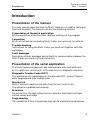
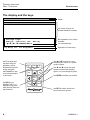
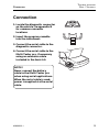
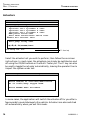
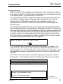
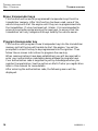
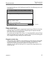
T
Trouble shooting – OPEL / VAUXHALL
O
/V
ROUBLE SHOOTING
PEL
AUXHALL
Preface
The program cassette in the Multi-Tester pro is the component which
gives the diagnostic equipment its unique test performance. The program
cassette can easily be changed to set the Multi-Tester pro up quickly for
the diagnostic task at hand.
The Multi-Tester pro software is available in two levels of functionality,
Plus line and Pro line. This manual covers the operation of the Pro line
cartridge. Although operation and display screens are identical for each
line, please be aware that some of the functions described are not available
on Plus line cartridges.
The Plus line cartridge has the following functions: engine DTC:s and
monitor list, airbag DTC:s, ABS DTC:s and service light resetting as well
as snapshots.
This fault-finding instruction describes the serial application for trouble
shooting via the diagnostic connector on Opel and Vauxhall.
Copyright AUTODIAGNOS
The contents of this document may be changed without prior notice, and should
therefore not be regarded as being binding on AUTODIAGNOS.
AUTODIAGNOS declines all responsibility for faults and omissions which may occur
in this document.
Under no circumstances can AUTODIAGNOS be held responsible for damage which
could occur due to use of this document, or of the hardware and software described
herein.
This document must not be wholly or partly reproduced, copied, or duplicated by any
means, nor may it be stored in an information retrieval system, except for personal
use, without written permission from AUTODIAGNOS. Nor may the contents be
divulged to any third party or used in any unauthorised manner. Any breach of these
stipulations may lead to legal action.
A0909032-1
1
TROUBLE SHOOTING
OPEL / VAUXHALL
CONTENTS
Contents
Preface ............................................................................................................. 1
Introduction ....................................................................................................... 3
Presentation of the manual ........................................................................... 3
Presentation of the serial application ............................................................ 3
The display and the keys .......................................................................... 4
Connection ....................................................................................................... 5
Trouble shooting ............................................................................................... 6
Start ............................................................................................................. 6
Select function ............................................................................................ 10
Monitor list .............................................................................................. 11
Read DTCs ............................................................................................ 12
Clear DTCs ............................................................................................ 13
Actuators ................................................................................................ 14
Programming .......................................................................................... 15
Erase transponder keys .......................................................................... 16
Program transponder key ....................................................................... 16
Erase remote keys .................................................................................. 17
Program remote key ............................................................................... 17
Snapshots .................................................................................................. 18
View snapshots ...................................................................................... 19
Load snapshots to PC ............................................................................ 20
Fault messages .......................................................................................... 21
Fault in data transmission ....................................................................... 21
Blink code read-out ..................................................................................... 22
2
A0909032-1
INTRODUCTION
TROUBLE SHOOTING
OPEL / VAUXHALL
Introduction
Presentation of the manual
This user manual describes how the Multi-Tester pro is used for testing on
Opel and Vauxhall. The manual contains the following sections:
Presentation of the serial application
Brief presentation of the functions, displays and keys of the program.
Connection
Brief instructions for connecting Multi-Tester pro hand unit to a vehicle.
Trouble shooting
Instructions for using the Multi-Tester pro hand unit together with the
application.
Fault messages
Description of fault messages during faults in communication between the
Multi-Tester pro hand unit and the vehicle.
Presentation of the serial application
The Multi-Tester pro hand unit can communicate with most electronic
ECU:s (electronic control unit) in the vehicle via a diagnostic connector.
Diagnostic Trouble Codes (DTC)
The application can read diagnostic trouble codes DTC, present these in
plain language and clear trouble codes.
Monitor list
Multi-Tester pro reads current data from the car’s control unit.
The values are updated continuously.
Actuators
On some ECUs, the application can force actuator functions to activate
various valves and relays.
Programming
On Immobiliser ECUs, transponder keys can be erased and programmed.
A0909032-1
3
TROUBLE SHOOTING
OPEL / VAUXHALL
INTRODUCTION
The display and the keys
1998:Engine:X20XEV (2 DTCs found)
Header
IAT circuit
Throttle contact
List of menu choices, the
selected alternative is marked
Voltage high
Status: Inactive (no: P0110)
é/ê/ç/è/ENTER/EXIT
F1:Help F2: F3:Snapshot
Use F1 to get general
help about using the
application, such as
keyboard functions and
screen information.
Use F2 and F3 to carry
out functions described
on the screen.
F1
Brief explanation of the chosen
alternative
List of permitted keys
Explanation of function keys
F2
F3
NO
YES
Use é and ê to move the cursor
between menu choices, or to update
groups of figures.
Use ç and è to move the cursor
between numbers when updating
figures, or to move through long texts.
Use ENTER to activate your selection.
HELP
Use HELP to get
diagnostic help, i.e. a
description of the faults
which the Multi-Tester pro
has discovered.
4
EXIT
ENTER
Use EXIT to leave a function and
return to the previous menu.
A0909032-1
CONNECTION
TROUBLE SHOOTING
OPEL / VAUXHALL
Connection
1. Locate the diagnostic connector
on the vehicle. Se appendix B
for common connector
locations.
2. Insert the program cassette
into the instrument.
3. Connect the serial cable to the
diagnostic connector.
4. Connect the serial cable to the
Multi-Tester pro, if necessary
using an extension cable
included in the basic kit.
NOTE!
Never connect the battery
cable to the Multi-Tester pro
when using serial applications.
When the serial cable is used,
power is supplied via the serial
cable.
A0909032-1
5
TROUBLE SHOOTING
OPEL / VAUXHALL
TROUBLE SHOOTING
Trouble shooting
Start
The program starts automatically each time the tool is connected to the
diagnostic socket.
The Multi-Tester pro executes a self-diagnosis routine when it boots up,
then displays the current version of software.
NOTE!
The ignition must be switched on to allow the instrument to contact
the ECU.
NOTE!
If the instrument is used when driving, an assistant must operate the
instrument.
1. Select “Diagnose” in the main menu
Use é and ê to move the cursor between menu choices, then press ENTER.
Opel/Vauxhall main menu
Diagnose
Snapshots
Go to diagnose menu
é/ê/ç/è/ENTER/EXIT
F1:Help F2: F3:
6
A0909032-1
TROUBLE SHOOTING
OPEL / VAUXHALL
TROUBLE SHOOTING
2. Select car model
Use é and ê to move the cursor between menu choices, then press ENTER.
Diagnose
CORSA-A/NOVA
êCORSA-B
êFRONTERA
êKADETT/ASTRA/BELMONT
êOMEGA-A/CARLTON
êOMEGA-B
êSENATOR
êSINTRA
Select model
é/ê/ç/è/ENTER/EXIT
F1:Help F2: F3:
3. Select year
Use é and ê to move the cursor between menu choices, then press ENTER.
Diagnose:VECTRA-B
1996
1997
1998
Select year of manufacture
é/ê/ç/è/ENTER/EXIT
F1:Help F2: F3:
A0909032-1
7
TROUBLE SHOOTING
OPEL / VAUXHALL
TROUBLE SHOOTING
4. Select test area
Use é and ê to move the cursor between menu choices, then press ENTER.
Diagnose:VECTRA-B:1998
Engine
Transmission
Chassis
Body
Select system type
é/ê/ç/è/ENTER/EXIT
F1:Help F2: F3:
5. Select system/engine code
Use é and ê to move the cursor between menu choices, then press ENTER.
Diagnose:VECTRA-B:1998:Engine
16L22
êX16SZR
êX16XEL
êX18XE
ê20NEJ
êC20SEL
êX20DTL
êX20XEV
Select system
é/ê/ç/è/ENTER/EXIT
F1:Help F2: F3:
8
A0909032-1
TROUBLE SHOOTING
TROUBLE SHOOTING
OPEL / VAUXHALL
After the system/engine code has been selected, the application will
attempt to connect to the selected ECU. When communication is
established, a message similar to the following will be displayed.
Diagnose:ASTRA-0:1990:Engine
Identification
90569370
Simtec 70 - X18XE1
Variant Coding:
Word = 803
ECU Id - 155 Selected
Press ENTER
This shows the system selected, and the details of the ECU found on
the vehicle. It is important to check the details reported here are correct.
If an engine code is selected which is different to the one actually in the
car, you will see a message similar to the one below.
Diagnose:ASTRA-G:1998:Engine
Identification
90569370
Multec-F - X18XE1
Variant Coding:
Word = 901
Warning Mismatched ECU!
ECU Id - 131 Selected
Press ENTER
In this example, you should reconnect with the correct engine type
selected.
A0909032-1
9
TROUBLE SHOOTING
OPEL / VAUXHALL
TROUBLE SHOOTING
Select function
Use é and ê to move the cursor between menu choices, then press ENTER.
Diagnose:ASTRA-G:1998:Engine:X18XE1
Monitor list
Read DTCs
Clear DTCs
Actuators
Actuators
é/ê/ç/è/ENTER/EXIT
F1: F2: F3:
The functions available will depend on the ECU chosen on the previous
screen. Programming is only available for Immobiliser, Central locking,
and Anti-theft warning ECUs. The Actuators option is only available on
ABS and some engine ECUs.
Each function is described on the following pages.
For some choices of engine version you will be advised to use blink code
read out or parallel diagnostics. This is further described in Appendix A.
KADETT/ASTRA/BELMONT:1991:Engine:C16NZ
To diagnose this system please
use the MULTEC 56 application or
consult the trouble shooting manual,
appendix "blink code read out".
Press ENTER
10
A0909032-1
TROUBLE SHOOTING
TROUBLE SHOOTING
OPEL / VAUXHALL
Monitor list
Multi-Tester pro reads current data from the car’s control unit.
The values are updated continuously.
1. Use é and ê to move the cursor between parameters.
2. Press ENTER to show selected parameter in the description field.
ASTRA-F:1998:Engine:X14NZ:Monitor list
Battery Voltage . . . . . . .
11,9 V
Coolant Temp . . . . . . . . .
146 °C
Map Sensor . . . . . . . . .
0,53 bar
Throttle Position sensor sig. . .
0 %
Engine speed. . . . . . . . . .
0 RPM
Idle air control . . . . . . .
0 step
02 Sensor loop . . . . . . . .
Open
02 Sensor . . . . . . . . . .
548 mV
Coolant Temp . . . . . . . . .
146 °C
Data Parameter name
Description Field
é/ê/ç/è/ENTER/EXIT
F1:Help F2: F3:Snapshot
A0909032-1
F1: User help
F3: Snapshot
11
TROUBLE SHOOTING
OPEL / VAUXHALL
TROUBLE SHOOTING
Read DTCs
All registered DTC:s (diagnostic trouble codes) in the relevant ECU are
indicated on the display.
1. Use é and ê to move the cursor for more information.
More information about the fault is then shown on the display. The
numerical codes can be used if you want to look in the service literature
for more information about the component or fault.
1998:Engine:X20XEV (2 DTCs found)
IAC circuit
Throttle contact
Year, Type, System and
number of DTC:s found
List of faulty components
Fault description of the
selected component
Status of the selected
component
Voltage high
Status:Inactive (no:P0110)
é/ê/ç/è/ENTER/EXIT
F1:Help F2: F3:Snapshot
Numerical code for the
fault type
F1: User help
F3: Save information
2. For some DTC:s, you can get information about the selected
component. Press HELP or ENTER.
Further information about the component is shown on the display.
Use é and ê to scroll through the help text and use ç and è to scroll
one screen at a time.
IAT circuit
INTAKE MANIFOLD AIR TEMP SENSOR:
This sensor consists of a temperature
sensitive resistor located in the air
intake system, or integrated in the
air flow meter housing. Its resistance
changes with the temperature, which
influences the voltage to the
electronic control unit.
é/ê/ç/è/ENTER/EXIT
12
A0909032-1
TROUBLE SHOOTING
TROUBLE SHOOTING
OPEL / VAUXHALL
Clear DTCs
NOTE!
You can not delete the DTC memory before you have read the DTC
memory.
1. Confirm deletion with YES or cancel the function with NO.
A0909032-1
13
TROUBLE SHOOTING
OPEL / VAUXHALL
TROUBLE SHOOTING
Actuators
Diagnose:ASTRA-G:1998:Engine:X18XE1
Fuel pump relay test
Ignition coil cylinder 1 test
Ignition coil cylinder 2 test
Ignition coil cylinder 3 test
Ignition coil cylinder 4 test
EGR pulse ratio test
Fuel tank ventilation valve test
êIdle air control test
Fuel pump relay test
é/ê/ç/è/ENTER/EXIT
F1:Help F2: F3:
F1: User help
Select the actuator test you wish to perform, then follow the on-screen
instructions. In most cases, the actuators can simply be switched on and
off using the YES/NO buttons on the Multi-Tester pro. The F1 key can also
be used to toggle the actuator automatically, leaving the operator free to
inspect the system under test.
Diagnose:ASTRA-G:1998:Engine:X10XE1
Press YES/NO to activate/deactivate.
F1 to start/stop toggle mode.
Press ENTER when finished.
In some cases, the application will switch the actuator off for you after a
few seconds to avoid damage to the vehicle. Actuators are also switched
off automatically when you exit this mode.
14
A0909032-1
TROUBLE SHOOTING
OPEL / VAUXHALL
TROUBLE SHOOTING
Programming
This function is only available on Immobiliser, Central locking, and Antitheft warning ECUs. It allows the transponder keys and remote-key fobs
to be erased and/or programmed for the vehicle.
For Immobiliser systems, transponder keys can be programmed into the
Immobiliser memory so that they may start the vehicle. For Central
locking or Anti-theft warning systems, the remote-key fob can be
programmed into the ECU so that it may be used to remotely operate
the door locks.
For Immobilisers and Anti-theft warning systems a four-digit pass code
must be entered before programming is allowed by the ECU. On entering
the programming menu, you will be asked for the four-digit pass code for the
car. This code can be found on the car pass supplied with the vehicle, and
is used to prevent unauthorised access to the key programming functions.
If the car pass is not available, the code can be obtained from a main dealer.
The vehicle registration details will be required.
Enter 4 digit vehicle pass code
0000
If an incorrect code is entered, you will be prompted to try again. It is
important to enter the pass code carefully as the ECU will activate it’s
security wait timer if an invalid pass code is entered. In this mode, it will
be impossible to erase or program keys until the security wait time has
expired.
Once the correct pass code is entered, the programming menu will be
displayed. For Immobiliser systems the following options are available.
Diagnose:ASTRA-G:2000:Body:IMMOBILISER
Erase transponder keys
Program transponder key
Erase transponder keys
é/ê/ç/è/ENTER/EXIT
F1:Help F2: F3:Snapshot
A0909032-1
F1: User help
F3: Save information
15
TROUBLE SHOOTING
OPEL / VAUXHALL
TROUBLE SHOOTING
Erase transponder keys
This function will erase all programmed transponder keys from the
Immobiliser memory. After this function has been used, none of the
vehicle’s keys will start the engine until they are re-programmed into
the Immobiliser. If a key has been lost / stolen, it is recommended to
erase all keys before programming the new keys, to ensure that the
Immobiliser will only recognise the keys held by the vehicle owner.
Program transponder key
This function will program a new transponder key into the Immobiliser
memory so that the key will be able to start the engine. You will be
prompted to insert the key to be programmed into the ignition. Then
follow the on-screen instructions to program the new key.
When communications have been established, you will be required to
enter your authorisation code before being allowed to program keys.
Your authorisation code is supplied to you by Autodiagnos when you
register the application. See the section on Multi-Tester pro registration
later in this manual for more details.
After entering the authorisation code, the following menu will be
displayed.
16
A0909032-1
TROUBLE SHOOTING
TROUBLE SHOOTING
OPEL / VAUXHALL
For Central locking or Anti-theft warning ECUs, the following menu will
be displayed.
Diagnose:ASTRA-G:2000:Body:CENTRAL LOCKING
Erase remote keys
Program remote key
Erase remote keys
é/ê/ç/è/ENTER/EXIT
F1:Help F2: F3:
F1: User help
Erase remote keys
This function will erase all programmed remote keys. After this function
has been used, none of the vehicle’s remote keys will operate the door
locks until they are re-programmed.
If a remote key has been lost / stolen, it is recommended to erase all keys
before programming the new keys, to ensure that the central locking will
only recognise the keys held by the vehicle owner.
Program remote key
This function will program a new remote key so that the key will be able
to operate the door locks. You will be prompted to activate the remote
key several times by pressing the button on the key fob. This is
necessary for the central locking ECU to record the unique code for the
remote key fob.
A0909032-1
17
TROUBLE SHOOTING
OPEL / VAUXHALL
TROUBLE SHOOTING
Multi-Tester pro Registration
As a security feature, the Multi-Tester pro application must be
registered before the key programming functions are available.
To register your Multi-Tester pro application you must return the
registration card supplied with the software to Autodiagnos. You will
then be given an authorisation code, which you can use to enable the
key programming functions of the software.
To register the Multi-Tester pro, use the “Multi-Tester pro Registration”
option on the main menu. You will be prompted to enter the serial
number of the tester, which can be found, on the back of the unit. You
will then be prompted to enter the authorisation code supplied to you
when you registered the product.
You will also be required to enter the authorisation code each time you
use the application to erase or program transponder keys on a vehicle.
18
A0909032-1
TROUBLE SHOOTING
TROUBLE SHOOTING
OPEL / VAUXHALL
Snapshots
All screens that display data received from the vehicle can be saved as
“snapshots” in Multi-Tester pro.
The Multi-Tester pro Opel/Vauxhall-application can store a maximum of
16 snapshots.
This menu lets you view the snapshots and download the snapshots to a PC.
1. Use é and ê to move the cursor between menu choices, then press
ENTER.
Snapshots menu
View snapshots
Download snapshot to PC
View saved snapshots
é/ê/ç/è/ENTER/EXIT
F1:Help F2: F3:
A0909032-1
F1: User help
19
TROUBLE SHOOTING
OPEL / VAUXHALL
TROUBLE SHOOTING
View snapshots
This function displays the saved snapshots.
1. Use é and ê to move the cursor and press ENTER to view selected
snapshot.
Select snapshot
Astra-F:C14NZ:Monitor list
êAstra-F:C14NZ:DTCs
êCorsa-B:ABS5.3:DTCs
Astra-F:C14NZ:Monitor list
é/ê/ç/è/ENTER/EXIT
F1:Help F2:Delete F3:
20
F1: User help
F2: Delete highlighted
information
A0909032-1
TROUBLE SHOOTING
TROUBLE SHOOTING
OPEL / VAUXHALL
Load snapshots to PC
Use this function for communication between Multi-Tester pro and a PC.
See the manual for the PC-program for more information.
A0909032-1
21
TROUBLE SHOOTING
OPEL / VAUXHALL
TROUBLE SHOOTING
Fault messages
Fault in data transmission
If the Multi-Tester pro loses contact with the ECU, the following
message will be displayed.
Com Error
Press ENTER
22
A0909032-1
TROUBLE SHOOTING
OPEL / VAUXHALL
APPENDIX A
Blink code read-out
To read out DTC:s using the blink code method, do like this.
1. Bridge pin A and B in the diagnostic connector.
Vehicle diagnostic connector (front view)
2.
3.
4.
5.
Turn ignition on.
Count the flashes on the “Check engine” lamp.
Translate them using the list below.
To erase the fault codes, disconnect battery for >20 seconds.
Blink Code interpretation
The code read out always starts with “Code 12” repeated three times,
after this the fault codes are flashed. All codes are repeated three times,
the first digit is flashed with a space of 0.4 seconds, then there is a 1.2
second delay until the second digit is flashed. The delay between codes is
3.2 seconds. Each code is repeated three times.
Example, Code 22 (Throttle potentiometer voltage low):
3.2s
1.2s
(1)
=> 3.2s
0.4s
3.2s
(2)
0.4s
First digit (2)
*3times =>
= Code 12 (start code)
1.2s
“separator“
0.4s
3.2s *3times
Second digit (2)
= Code 22
The sequence is ended by three times flashing of code 12.
A0909032-1
23
TROUBLE SHOOTING
OPEL / VAUXHALL
APPENDIX A
Diagnostic Trouble Codes
Code Fault description
12
Start of code sequence, or no fault found.
13
Oxygen sensor not switching
14
Coolant temperature sensor voltage low
15
Coolant temperature sensor voltage high
21
Throttle potentiometer voltage high
22
Throttle potentiometer voltage low
24
Road speed sensor no signal
33
MAP sensor voltage high
34
MAP sensor voltage low
35
Idle speed control no function
42
Ignition adjustment no function
44
Oxygen sensor voltage low
45
Oxygen sensor voltage high
51
EPROM faulty
53
Battery voltage high
54
CO-potentiometer out of range
55
ECU faulty
24
A0909032-1
APPENDIX B
TROUBLE SHOOTING
OPEL / VAUXHALL
Common diagnostic connector locations
Common diagnostic connector locations for recent Vauxhall/Opel models
are listed below. For older vehicles, the diagnostic connector can often be
found in the engine compartment.
Astra-F
16 pin OBD connector located in the fuse compartment to the right hand
side of the steering wheel on RHD vehicles and to the left hand side of
the steering wheel on LHD vehicles. Covering panel can be pulled off to
reveal the complete fuse compartment and diagnostic connector.
Astra-G
16 pin OBD connector located in the central console between the
handbrake and the gearstick. There is a plastic cover that needs to be
removed to find the connector. This can be done with a medium sized
flat-blade screwdriver inserted at the front of the panel (nearest to the
gearstick).
Corsa-B/Tigra
16 pin OBD connector located in the fuse compartment to the right hand
side of the steering wheel on RHD vehicles and to the left hand side of
the steering wheel on LHD vehicles. Covering panel can be pulled off to
reveal the complete fuse compartment and diagnostic connector.
Frontera
16 pin OBD connector mounted vertically just in front of the hinge of the
driver side door.
Omega-B
16 pin OBD connector located in the fuse compartment. There is a large
cover for this compartment directly below the steering wheel. A push
button releases the cover and reveals the fuses and diagnostic connector.
A0909032-1
25
TROUBLE SHOOTING
OPEL / VAUXHALL
APPENDIX B
Vectra-B
16 pin OBD connector located in the central console between the
handbrake and the gearstick. Access is very similar to the Astra-G
except that the covering panel is best removed by inserting a
screwdriver at the rear of the cover (nearest to the handbrake).
Zafira
16 pin OBD connector located in the central console between the
handbrake and the gearstick. There is a plastic cover that needs to be
removed to find the connector. This can be done with a medium sized
flat-blade screwdriver inserted at the front of the panel (nearest to the
gearstick).
26
A0909032-1