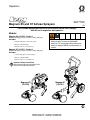
1
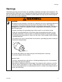
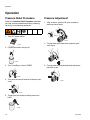
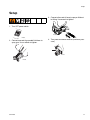
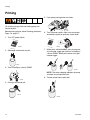
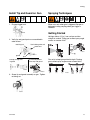
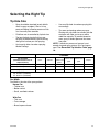
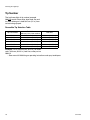
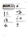
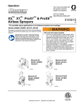
Operation
3A1775C
Magnum X5 and X7 Airless Sprayers
EN
- For Portable Spray Applications of Architectural Paints and Coatings - Not for use in explosive atmospheres -
Models:
Magnum X5 (16J750) - Series A
Maximum Working Pressure: 207 bar, 21 MPa (3000 PSI)
Includes:
•0.91 lpm (0.24 gpm) stand-mount sprayer
•SG2 gun - Manual 312830
•0.635 cm (1/4 in) x 7.5 m (25 ft) hose
• Use water-based or mineral spirit-type
materials only. Do not use flammable
materials. For more information about your
material, request MSDS from distributor or
retailer.
Magnum X7 (16J751) - Series A
Maximum Working Pressure: 207 bar, 21 MPa (3000 PSI)
Includes:
•1.17 lpm (0.31 gpm) cart-mount sprayer
•SG3 gun - Manual 312830
•0.635 cm (1/4 in.) x 15 m (50 ft) hose
Important Safety Instructions
Read all warnings and instructions in this
manual. Save these instructions.
Magnum X5
(16J750)
Magnum X7
(16J751)
Table of Contents
Warnings . . . . . . . . . . . . . . . . . . . . . . . . . . . . . . . . . 3
Grounding Instructions . . . . . . . . . . . . . . . . . . . . . . 7
Thermal Overload . . . . . . . . . . . . . . . . . . . . . . . . 7
Component Identification (Magnum X5) . . . . . . . . 8
Component Identification (Magnum X7) . . . . . . . . 9
Operation . . . . . . . . . . . . . . . . . . . . . . . . . . . . . . . . 10
Pressure Relief Procedure . . . . . . . . . . . . . . . . 10
Pressure Adjustment . . . . . . . . . . . . . . . . . . . . . 10
Setup . . . . . . . . . . . . . . . . . . . . . . . . . . . . . . . . . . . . 11
Priming . . . . . . . . . . . . . . . . . . . . . . . . . . . . . . . . . . 12
Install Tip and Guard on Gun . . . . . . . . . . . . . . 13
Spraying Techniques . . . . . . . . . . . . . . . . . . . . . 13
Getting Started . . . . . . . . . . . . . . . . . . . . . . . . . 13
Unclogging Spray Tip . . . . . . . . . . . . . . . . . . . . 14
Triggering Gun . . . . . . . . . . . . . . . . . . . . . . . . . 14
Aiming Gun . . . . . . . . . . . . . . . . . . . . . . . . . . . . 14
Selecting the Right Tip . . . . . . . . . . . . . . . . . . . . . 15
Tip Hole Size . . . . . . . . . . . . . . . . . . . . . . . . . . . 15
Tip Number . . . . . . . . . . . . . . . . . . . . . . . . . . . . 16
2
Cleanup . . . . . . . . . . . . . . . . . . . . . . . . . . . . . . . . . . 17
Cleaning Gun Filter . . . . . . . . . . . . . . . . . . . . . . 18
Filling Sprayer with Storage Fluid . . . . . . . . . . . 19
Maintenance . . . . . . . . . . . . . . . . . . . . . . . . . . . . . . 20
Caring for Sprayer . . . . . . . . . . . . . . . . . . . . . . . 20
Gun Fluid Filter . . . . . . . . . . . . . . . . . . . . . . . . . 20
Paint Hoses . . . . . . . . . . . . . . . . . . . . . . . . . . . . 20
Tips . . . . . . . . . . . . . . . . . . . . . . . . . . . . . . . . . . 20
Pump Check Valves . . . . . . . . . . . . . . . . . . . . . . 20
Pump . . . . . . . . . . . . . . . . . . . . . . . . . . . . . . . . . 20
Troubleshooting . . . . . . . . . . . . . . . . . . . . . . . . . . . 21
Technical Data . . . . . . . . . . . . . . . . . . . . . . . . . . . . 24
Notes . . . . . . . . . . . . . . . . . . . . . . . . . . . . . . . . . . . . 25
Graco Standard Warranty . . . . . . . . . . . . . . . . . . . 26
3A1775C
Warnings
Warnings
The following warnings are for the setup, use, grounding, maintenance and repair of this equipment. The
exclamation point symbol alerts you to a general warning and the hazard symbol refers to procedure-specific risks. Refer back to these warnings. Additional, product-specific warnings may be found throughout
the body of this manual where applicable.
WARNING
GROUNDING
This product must be grounded. In the event of an electrical short circuit, grounding reduces the
risk of electric shock by providing an escape wire for the electric current. This product is
equipped with a cord having a grounding wire with an appropriate grounding plug. The plug must
be plugged into an outlet that is properly installed and grounded in accordance with all local
codes and ordinances.
• Improper installation of the grounding plug is able to result in a risk of electric shock.
• Check with a qualified electrician or serviceman when the grounding instructions are not
completely understood, or when in doubt as to whether the product is properly grounded.
• Do not modify the plug provided; if it does not fit the outlet, have the proper outlet installed by
a qualified electrician.
• This product is for use on a nominal 230V circuit and has a grounding plug similar to the plug
illustrated in the figure below.
ti11376a
Only connect the product to an outlet having the same configuration as the plug.
Do not use an adapter with this product.
Extension Cords:
• Use only a 3-wire extension cord that has a 3-blade grounding plug and a 3-slot receptacle
that accepts the plug on the product.
• Make sure your extension cord is not damaged. If an extension cord is necessary, use 15m
(49.2 ft) 1.0 mm2, 30m (98.4 ft) 1.5 mm2, or 50m (164.0 ft) 2.5 mm2 minimum to carry the
current that the product draws. An undersized cord results in a drop in line voltage and loss of
power and overheating.
3A1775C
3
Warnings
WARNING
FIRE AND EXPLOSION HAZARD
Flammable fumes, such as solvent and paint fumes, in work area can ignite or explode. To help
prevent fire and explosion:
• Do not spray or clean with flammable materials [flash points lower than 100° F (38° C)]. Use
•
•
•
•
•
•
•
•
•
•
•
•
•
water-based material or mineral spirits-type material only. For complete information about
your fluid, request the MSDS from the fluid distributor or retailer.
Do not spray flammable or combustible materials near an open flame or sources of ignition
such as cigarettes, motors, and electrical equipment.
Only use water-based or mineral spirit-type materials with a flash point greater than 70° F
(21° C).
Paint or solvent flowing through the equipment is able to result in static electricity. Static
electricity creates a risk of fire or explosion in the presence of paint or solvent fumes. All parts
of the spray system, including the pump, hose assembly, spray gun, and objects in and
around the spray area shall be properly grounded to protect against static discharge and
sparks. Use Graco conductive or grounded high-pressure airless paint sprayer hoses.
Verify that all containers and collection systems are grounded to prevent static discharge. Do
not use pail liners unless they are antistatic or conductive.
Connect to a grounded outlet and use grounded extensions cords. Do not use a 3-to-2
adapter.
Do not use a paint or a solvent containing halogenated hydrocarbons.
Keep spray area well-ventilated. Keep a good supply of fresh air moving through the area.
Keep pump assembly in a well ventilated area. Do not spray pump assembly.
Do not smoke in the spray area.
Do not operate light switches, engines, or similar spark producing products in the spray area.
Keep area clean and free of paint or solvent containers, rags, and other flammable materials.
Know the contents of the paints and solvents being sprayed. Read all Material Safety Data
Sheets (MSDS) and container labels provided with the paints and solvents. Follow the paint
and solvents manufacturer’s safety instructions.
Fire extinguisher equipment shall be present and working.
Sprayer generates sparks. When combustible materials are used in or near the sprayer or for
flushing or cleaning, keep sprayer at least 20 feet (6 m) away from explosive vapors.
ELECTRIC SHOCK HAZARD
This equipment must be grounded. Improper grounding, setup, or usage of the system can
cause electric shock.
• Turn off and disconnect power at main switch before disconnecting any cables and before
servicing equipment.
• Connect only to grounded power source.
• All electrical wiring must be done by a qualified electrician and comply with all local codes and
regulations.
4
3A1775C
Warnings
WARNING
SKIN INJECTION HAZARD
High-pressure fluid from gun, hose leaks, or ruptured components will pierce skin. This may look
like just a cut, but it is a serious injury that can result in amputation. Get immediate surgical
treatment.
• Do not spray without tip guard and trigger guard installed.
• Engage trigger lock when not spraying.
• Do not point gun at anyone or at any part of the body.
• Do not put your hand over the spray tip.
• Do not stop or deflect leaks with your hand, body, glove, or rag.
• Follow the Pressure Relief Procedure when you stop spraying and before cleaning,
checking, or servicing equipment.
• Tighten all fluid connections before operating the equipment.
• Check hoses and couplings daily. Replace worn or damaged parts immediately.
EQUIPMENT MISUSE HAZARD
Misuse can cause death or serious injury.
• Do not operate the unit when fatigued or under the influence of drugs or alcohol.
• Do not exceed the maximum working pressure or temperature rating of the lowest rated
•
•
•
•
•
•
•
•
•
•
•
3A1775C
system component. See Technical Data in all equipment manuals.
Use fluids and solvents that are compatible with equipment wetted parts. See Technical Data
in all equipment manuals. Read fluid and solvent manufacturer’s warnings. For complete
information about your material, request MSDS from distributor or retailer.
Do not leave the work area while equipment is energized or under pressure.
Turn off all equipment and follow the Pressure Relief Procedure when equipment is not in
use.
Check equipment daily. Repair or replace worn or damaged parts immediately with genuine
manufacturer’s replacement parts only.
Do not alter or modify equipment. Alterations or modifications may void agency approvals and
create safety hazards.
Make sure all equipment is rated and approved for the environment in which you are using it.
Use equipment only for its intended purpose. Call your distributor for information.
Route hoses and cables away from traffic areas, sharp edges, moving parts, and hot
surfaces.
Do not kink or over bend hoses or use hoses to pull equipment.
Keep children and animals away from work area.
Comply with all applicable safety regulations.
5
Warnings
WARNING
PRESSURIZED ALUMINUM PARTS HAZARD
Use of fluids that are incompatible with aluminum in pressurized equipment can cause serious
chemical reaction and equipment rupture. Failure to follow this warning can result in death,
serious injury, or property damage.
• Do not use 1,1,1-trichloroethane, methylene chloride, other halogenated hydrocarbon
solvents or fluids containing such solvents.
• Many other fluids may contain chemicals that can react with aluminum. Contact your material
supplier for compatibility.
TOXIC FLUID OR FUMES HAZARD
Toxic fluids or fumes can cause serious injury or death if splashed in the eyes or on skin, inhaled,
or swallowed.
• Read MSDSs to know the specific hazards of the fluids you are using.
• Store hazardous fluid in approved containers, and dispose of it according to applicable
guidelines.
RECOIL HAZARD
Gun may recoil when triggered. If you are not standing securely, you could fall and be seriously
injured.
PERSONAL PROTECTIVE EQUIPMENT
Wear appropriate protective equipment when in the work area to help prevent serious injury,
including eye injury, hearing loss, inhalation of toxic fumes, and burns. This protective equipment
includes but is not limited to:
• Protective eyewear, and hearing protection.
• Respirators, protective clothing, and gloves as recommended by the fluid and solvent
manufacturer.
6
3A1775C
Grounding Instructions
Grounding Instructions
3. Do not use an extension cord with damaged
ground plug.
Recommended extension cords:
Sprayer must be grounded. Grounding reduces
the risk of static and electric shock by providing an
escape wire for electrical current due to static build
up or in the event of a short circuit.
1. This sprayer requires 220-240 VAC, 50/60 Hz
10A circuit with a grounding receptacle. Never
use an outlet that is not grounded.
ti7529b
•
15 m (49.2 ft) 1.0 mm2
•
30 m (98.4 ft) 1.5 mm2
•
50 m (164.0 ft) 2.5 mm2
4. Smaller gauge or longer extension cords may
reduce sprayer performance.
Thermal Overload
Motor has a thermal overload switch to shut itself
down if overheated. If unit overheats, allow approximately 45 minutes for unit to cool. Once cool,
switch will close and unit will restart.
2. Do not use sprayer if electrical cord has damaged ground prong.
To reduce risk of injury from motor starting
unexpectedly when it cools, always turn power
switch OFF if motor shuts down.
ti7528a
3A1775C
7
Component Identification (Magnum X5)
Component Identification (Magnum X5)
B
A
Z
J
C
S
Q
G
V
H
L
K
R
P
T
D
U
ti15963b
M
A
B
C
D
G
H
J
K
8
Electric motor (inside enclosure)
Power switch
Pressure control knob
Pump fluid outlet fitting
Suction Tube
Prime tube (with diffuser)
Prime/Spray valve control
Fluid inlet connection and inlet valve
L
M
P
Q
R
S
T
V
Z
Inlet screen
Paint hose
SG2 airless spray gun
Tip guard
Reversible spray tip
Trigger safety lever
Gun fluid inlet fitting
Gun fluid filter (in handle)
Pump Priming Button
3A1775C
Component Identification (Magnum X7)
Component Identification (Magnum X7)
B
W
A
J
Z
C
K
X
H
Q
D
S
G
V
P
T
L
R
U
A
B
C
D
G
H
J
K
L
Electric motor (inside enclosure)
Power switch
Pressure control knob
Pump fluid outlet fitting
Suction Tube
Prime tube (with diffuser)
Prime/Spray valve control
Fluid inlet connection and inlet valve
Inlet screen
3A1775C
M
ti15964b
M
P
Q
R
S
T
V
W
X
Z
Paint hose
SG3 airless spray gun
Tip guard
Reversible spray tip
Trigger safety lever
Gun fluid inlet fitting
Gun fluid filter (in handle)
Hose/cord wrap bracket
Pail hanger
Pump Priming Button
9
Operation
Operation
Pressure Relief Procedure
Pressure Adjustment
Follow this Pressure Relief Procedure whenever
you stop spraying and before cleaning, checking,
servicing, or transporting equipment.
1. Align arrow on sprayer with spray symbol on
pressure control knob.
1. Turn OFF power switch.
ti2031a
ti2018a
2. Turning knob right (clockwise) increases pressure at gun.
2. Place prime tube in waste pail.
ti2032a
ti2034a
3. Turn Prime/Spray valve to PRIME.
3. Turning knob left (counterclockwise) decreases
pressure at gun.
ti2019a
4. Turn pressure control knob left (minimum pressure).
ti2020a
ti2020a
5. Trigger gun into bucket to relieve pressure in
hose.
ti2033a
10
3A1775C
Setup
Setup
3. Connect other end of hose to sprayer fluid outlet fitting. Use wrench to tighten.
1. Turn OFF power switch.
ti15965a
ti2018a
2. Connect one end of grounded fluid hose to
spray gun. Use a wrench to tighten.
4. Turn pressure control knob left (minimum pressure).
ti2020a
ti2024a
3A1775C
11
Priming
Priming
5. Push pump priming button two times.
For flushing storage fluid and loading pump and
hose with paint.
Before priming sprayer, follow Cleaning procedure,
Steps 1-6, page 17.
ti15972a
6. Turn ON power switch. Align arrow on sprayer
and bucket symbol on pressure control knob.
1. Turn OFF power switch.
ti2018a
2. Submerge suction tube in paint.
ti2028a
7. When paint, without bubbles, starts to come out
of prime tube, trigger gun and turn Prime/Spray
valve to SPRAY. When paint comes out of gun,
release trigger.
ti2026a
3. Turn Prime/Spray valve to PRIME.
ti2029a
NOTE: The motor stopping indicates the pump
and hose are primed with paint.
8. Transfer prime tube to paint pail.
ti2019a
4. Point gun into waste pail.
ti2027a
ti2030a
12
3A1775C
Priming
Install Tip and Guard on Gun
Spraying Techniques
1. Engage trigger lock.
Motor runs only when gun is triggered. Sprayer is
designed to stop pumping when gun trigger is
released.
Getting Started
ti8908a
2. Verify tip and guard parts are assembled in
order shown.
retaining nut
Hold gun 30 cm (12 in.) from surface and aim
straight at surface. Tilting gun to direct spray angle
causes an uneven finish.
black rubber gasket and
metal seat
ti2035a
guard
ti8911a
tip
Use tip to align seat
in guard
Tip must be pushed
all the way into guard
Flex wrist to keep gun pointed straight. Fanning
gun to direct spray angle causes uneven finish.
ti9574a
ti5606a
ti2036a
3. Screw tip and guard assembly on gun. Tighten
retaining nut.
ti9313a
3A1775C
13
Priming
Unclogging Spray Tip
5. When obstruction is cleared, engage trigger
lock and rotate arrow-shaped handle back to
SPRAY position.
To avoid fluid splash back:
• Never pull gun trigger when arrow-shaped
handle is between SPRAY and UNCLOG
positions.
• Tip must be pushed all the way into guard.
1. To UNCLOG tip obstruction, engage trigger
lock.
ti9049a
Point the arrow-shaped handle on the spray tip forward to SPRAY and backward to UNCLOG
obstructions.
Triggering Gun
Pull trigger after starting stroke, release trigger
before end of stroke. Gun must be moving when
trigger is pulled and released.
ti8908a
2. Point arrow-shaped handle backward to
UNCLOG position.
ti2037a
ti9048a
Aiming Gun
3. Aim gun at piece of scrap or cardboard.
4. Unlock trigger lock. Pull trigger to clear clog.
Aim tip of gun at edge of previous stroke to overlap
each stroke by half.
ti8909a
ti2038a
14
3A1775C
Selecting the Right Tip
Selecting the Right Tip
Tip Hole Size
•
Spray should be atomized (evenly distributed, no gaps or edges). Start at a low
pressure setting, increase pressure a little
at a time until paint atomizes.
•
Fluid flow rate is controlled by tip hole size.
•
The best tip hole size for fluid you are
spraying is determined by type of coating
and type of surface you are spraying.
•
Use large tip hole size when spraying
thicker coatings.
•
Use small tip hole size when spraying thinner coatings.
•
Tips wear and enlarge when you spray.
Starting with a tip hole size smaller than the
maximum will allow you to spray within
rated flow capacity. To prevent excessive
wear, spray at lowest pressure that atomizes paint.
NOTE: If maximum pressure of sprayer is not
enough for good spray pattern, tip is too large or
worn. See Reversible Tip Selection Table, page
16.
COATINGS
Tip Hole Size
stains
(diameter based on area of
elliptical orifice)
0.013 in. (0.33 mm)
0.015 in. (0.38 mm)
0.017 in. (0.43 mm)
Maximum Tip Size:
X5 - 0.015 in. (0.38 mm)
X7 - 0.017 in. (0.43 mm)
X
enamels
X
X
oil-based
primers and
paints
X
X
X
interior latex
paint
X
X
X
exterior latex
paint
X
X
acrylics
X
Fan Width
Fan Width is the size of the spray pattern.
Narrow Fan
• Thicker coat
• Better control
• Small, confined surfaces
Wide Fan
• Thin coat
• Fast coverage
• Broad, open surfaces
3A1775C
15
Selecting the Right Tip
Tip Number
The last three digits of tip number (example
286413) contain information about hole size and
fan width when gun is held 30.5 cm (12 in.) from
surface being sprayed.
Reversible Tip Selection Table
Tip Part Number
Fan Width
305 mm (12 in.) from surface
Hole Size
286313
286413
286415
286515
286417
286517
152-203 mm (6-8 in.)
203-254 mm (8-10 in.)
203-254 mm (8-10 in.)
254-305 mm (10-12 in.)
203-254 mm (8-10 in.)
254-305 mm (10-12 in.)
0.33 mm (0.013 in.)
0.33 mm (0.013 in.)
0.38 mm (0.015 in.)
0.38 mm (0.015 in.)
0.43 mm (0.017 in.)
0.43 mm (0.017 in.)
Example: For an 203-254 mm (8-10 in.) fan width
and a 0.33 mm (0.013 in.) hole size, order part no.
286413.
• See manual 312830 for gun operating instructions and spray techniques.
16
3A1775C
Cleanup
Cleanup
5. While pump continues to stroke, remove trigger
lock. Trigger gun into paint pail. Turn
Prime/Spray valve to SPRAY. Continue to trigger gun until flushing fluid comes out of gun.
Release trigger.
1. Engage gun trigger lock.
ti2051a
ti2048a
NOTE: To minimize splashing, aim gun at
inside wall of empty waste pail.
2. Turn OFF power switch. Turn Prime/Spray
valve to PRIME.
6. Move gun to waste pail. Trigger gun until
remaining flushing fluid is gone from flushing
pail. Release gun trigger.
ti2019a
ti2018a
3. Place prime tube in waste pail. Submerge suction tube in water or compatible solvent for
non-water based material.
ti2052a
7. Fill unit with Pump Armor or mineral spirits. See
Cleanup, page 17.
ti2050a
4. Turn ON power switch. Align arrow on sprayer
and bucket symbol on pressure control knob.
ti2028a
3A1775C
17
Cleanup
Cleaning Gun Filter
3. Remove filter and clean it in compatible solvent.
Perform Pressure Relief Procedure, page 10.
1. Engage gun trigger lock.
ti2055a
NOTE: Do not soak entire gun in solvent. Prolonged exposure to solvent can ruin packings.
4. Insert filter.
ti2048a
2. Unscrew hose.
ti2009a
ti2007
18
3A1775C
Cleanup
Filling Sprayer with Storage Fluid
Always pump storage fluid through pump system
after cleaning. Water left in sprayer will corrode
sprayer and damage pump.
1. Remove inlet strainer. Place suction tube in
storage fluid bottle and prime tube in waste
pail.
4. Turn ON power switch.
ti2028a1
5. Align arrow on sprayer with roller symbol on
pressure control knob.
ti2058a
6. When storage fluid comes out of prime tube
(5-10 seconds) turn OFF power switch.
ti2057a
2. Turn Prime/Spray valve to PRIME.
ti2059a
ti2019a
3. Turn pressure control knob all the way left
(counterclockwise) to minimum pressure.
7. Turn Prime/Spray valve to SPRAY to keep storage fluid in sprayer during storage.
ti2044a
ti2020a
3A1775C
19
Maintenance
Maintenance
Tips
•
Always clean tips with compatible solvent
and brush after spraying.
•
Tip life: 57 liters (15 gallons) - 227 liters (60
gallons)*
•
Do not spray with worn tip.
NOTICE
Openings in shroud provide air for cooling
mechanical parts and electronics inside. If water
gets in these openings sprayer could malfunction
or be permanently damaged.
Caring for Sprayer
Clean sprayer and accessories thoroughly after
each use.
Pump Check Valves
ti15970a
Do not cover vent holes or shroud while spraying.
•
Storing in water, inadequate flushing or
ingested debris can cause either of the two
check valves to malfunction.
•
If pump does not prime after 30 seconds,
try to loosen check balls by pushing pump
priming button or by tapping the inlet valve
with a small wrench as the sprayer is stroking.
Gun Fluid Filter
Clean gun fluid filter with compatible solvent and
brush every time you flush system. Replace when
damaged.
ti15972a
Paint Hoses
Check hose for damage every time you spray. Do
not attempt to clean or repair hose if hose jacket or
fittings are damaged. Do not use hoses shorter
than 7.5 m
(25 ft).
NOTE: Excessive shock will fracture or cause
other damage to pump.
NOTE: To verify inlet valve ball is sticking,
unscrew valves from pump and check them.
If sprayer continues to cycle (motor and pump
run) after you release gun trigger, pump valves
may be obstructed or worn. Valve repair kits
are available from Graco/MAGNUM authorized
service centers.
Pump
When pump wears, paint will begin to leak down
outside of pump. Replace pump at first sign of leaking or additional damage could occur.
Pump repair kits are available from Graco/MAGNUM
authorized service centers.
20
3A1775C
Troubleshooting
Troubleshooting
Problem
Pump will not prime
HINT:
• Attempt to free check balls by
Cause
Prime/Spray valve set at SPRAY.
Inlet screen clogged.
Suction tube is not immersed.
Inlet valve check ball stuck.
pushing pump priming
button.
• Attempt to free check balls by
tapping side of inlet valve as
sprayer is stroking.
• Strain paint before spraying.
Outlet valve check ball stuck.
Suction tube is leaking.
Prime/Spray valve clogged.
Keep sand and debris out.
• Thoroughly flush after every
Solution
Turn Prime/Spray valve to PRIME.
Clean debris off inlet screen.
Reposition suction tube in bottom of paint pail.
Remove tube. Insert end of pencil into inlet section to
dislodge ball. Press pump priming button, page 8. OR
Power Flush unit, page 17.
Unscrew outlet valve. Remove and clean assembly.
Tighten suction tube connection. Inspect for cracks or
vacuum leaks.
Clean/replace drain tube as necessary. Return sprayer
to Graco/MAGNUM authorized service center if drain
valve is clogged.
paint job.
• Do not store in water. Use
Pump Armor or mineral
spirits.
Power switch is on and sprayer is
plugged in but pump does not
cycle.
Pressure set at minimum.
Electrical outlet is not providing
power.
Turn pressure control knob right to increase pressure.
• Try a different outlet OR test outlet by plugging
something in that you know is working.
• Reset building circuit breaker or replace fuse.
Damaged extension cord.
Replace extension cord. See Grounding Instructions,
page 7.
Damaged sprayer electrical cord. Check for broken insulation or wires. Replace damaged
electrical cord.
Motor or control damaged.
Return sprayer to authorized Graco service center.
Paint frozen or hardened in pump. Unplug sprayer from electrical outlet.
If paint if frozen in sprayer:
Do NOT try to start frozen sprayer. Thaw completely or
you may damage motor, control board and/or drivetrain.
1 Turn OFF power switch.
2 Place sprayer in warm area for several hours.
3 Plug in and turn on sprayer.
4 Slowly increase pressure until motor starts.
If paint hardened in sprayer:
1 Replace pump packings.
2 Remove all residue from valves and passages.
3A1775C
21
Troubleshooting
Problem
Pump cycles but pressure does
not build up.
Cause
Pump not primed.
Inlet screen clogged.
Suction tube not immersed.
Paint pail empty.
Suction tube has vacuum air leak.
Pump check valves are dirty or
damaged.
Prime/Spray valve worn or
obstructed with debris.
Pump check ball stuck.
Cannot pull gun trigger.
Gun stops spraying.
Gun trigger safety engaged.
Spray tip clogged.
Pump cycles but paint only
dribbles or spurts when trigger is
pulled.
Pressure is set too low.
Spray tip clogged.
Spray tip too large or worn.
Gun filter clogged.
Fluid filter is clogged.
Pump check ball stuck.
Pressure set at maximum, but
cannot achieve good spray
pattern.
Tip is too large for sprayer.
Tip is worn beyond capability of
sprayer.
Gun filter clogged.
Inlet screen clogged.
Pump valves worn.
Solution
Prime pump, page 12.
Clean debris off inlet screen
Reposition suction tube in bottom of paint pail.
Refill paint pail and reprime sprayer.
Tighten suction tube connection. Inspect for cracks or
vacuum leaks. If cracked or damaged, replace.
Return sprayer to Graco/MAGNUM authorized service
center.
See “Pump will not prime” section of Troubleshooting
table. Press pump priming button two times.
Remove gun trigger safety
1 Turn arrow-shaped handle to unclog position.
2 Aim gun into waste pail.
3 Squeeze trigger.
4 Return arrow-shaped handle to spray position and
begin spraying.
Turn pressure control knob right to increase pressure.
Clean tip. See “Gun stops spraying” section of
Troubleshooting table.
Replace tip.
Clean or replace gun filter, page 18.
Clean or replace fluid filter.
See “Pump will not prime” section of Troubleshooting
table.
Select smaller tip, Tip Hole Size, page 15.
Replace tip.
Clean or replace gun filter, page 18.
Clean debris off inlet screen.
Check for worn pump valves:
1
2
Fluid filter clogged.
Extension cord too long or not
heavy enough gauge.
22
Prime sprayer with paint.
Trigger gun momentarily. When trigger is released,
pump should cycle and stop.
3 If pump continues to cycle, pump valves may be
worn.
4 Return sprayer to Graco/MAGNUM authorized
service center.
Clean or replace fluid filter.
Replace cord, Grounding Information, page 7.
3A1775C
Troubleshooting
Problem
Sprayed paint runs down wall or
sags.
Sprayed paint is not covering.
Pattern is inconsistent or leaving
stripes.
Cause
Solution
Going on too thick.
Move gun faster.
Use tip with smaller hole size.
Use tip with wider fan.
Move gun away from surface.
Going on too thin.
Move gun slower.
Use tip with larger hole size.
Use tip with narrower fan.
Move gun closer to surface.
Pressure set too low.
Turn pressure control knob right to increase pressure.
Spray tip worn beyond capability of Replace tip.
sprayer.
HINT:
Thin paint slightly with
water/solvent.
Motor is hot and runs
intermittently.
Vent holes in shroud are clogged
or sprayer is covered.
Extension cord too long or not
This is a Thermal Overload
heavy enough gauge.
condition. Motor will automatically
Unregulated electrical generator
shut off due to excessive heat.
being used has excessive voltage.
Damage can occur if cause is not
Sprayer was operated at high
corrected.
pressure with small tip, causing
frequent motor starts and
excessive heat build up.
Building circuit breaker opens after Too many appliances plugged in
sprayer operates for 5-10 minutes. on same circuit.
Extension cord is damaged, too
OR
long, or not a heavy enough
gauge.
Building circuit breaker opens as
Damaged sprayer electrical cord.
soon as sprayer is plugged into
outlet and sprayer is turned on.
Damaged motor or control.
Fan pattern varies dramatically
while spraying.
Sprayer does not turn on promptly
when resuming spraying.
Spray comes out of gun in two
thick streams.
Paint leaks down outside of pump.
Paint comes out of pressure
control knob.
Pressure drain actuates
automatically, relieving pressure
through prime tube.
3A1775C
Pressure control switch is worn
and causing excessive pressure
variation.
Reversible tip is in UNCLOG
position.
Worn pump packings.
Worn pressure control knob.
Clear vent holes.
Replace cord, Grounding Instructions, page 7.
Use electrical generator with proper voltage regulator.
Sprayer requires 220-240, VAC 50/60 Hz.
Decrease pressure setting or increase tip size.
Move sprayer to cooler location.
Unplug some appliances or use a less busy circuit.
Plug in something that you know is working to test
extension cord. Replace extension cord. Grounding
Instructions, page 7.
Check for broken insulation or wires. Replace damaged
electrical cord.
Return sprayer to Graco/MAGNUM authorized service
center.
Return sprayer to Graco/MAGNUM authorized service
center.
Rotate arrow-shaped handle on tip to SPRAY position.
Replace pump packings, see Pump manual.
Return sprayer to Graco/MAGNUM authorized service
center.
System is overpressuring.
23
Technical Data
Technical Data
X5
X7
Maximum fluid working pressure - sprayer
207 bar, 21 MPa (3000 psi)
Sprayer inlet size
3/4 in. internal thread (standard garden hose USA)
Sprayer outlet size
1/4 npsm external thread
Electric motor (open frame universal motor)
1/2 hp 4.5 Amp
5/8 hp 4.5 Amp
Sprayer weight only
6.1 kg (13.3 lb)
10.6 kg (23.3 lb)
Length
36.0 cm (14.5 in.)
49.5 cm (19.5 in.)
Width
31.5 cm (12.4 in.)
38.9 cm (15.3 in.)
Height
45.5 cm (17.9 in.)
94.0 cm (37.0 in.)
Dimensions:
Wetted parts sprayer
Stainless steel, brass, ultra-high molecular weight polyethylene
(UHMWPE) leather carbide, nylon, aluminum, PVC, polypropylene,
fluroelastomer
Inlet Screen on Suction Tube
450 micron (35 mesh)
Maximum material temperature
50° C (120° F)
Electrical power requirement
220 - 240V AC 50/60 Hz, 1 phase, 10A
Sound data spray gun:
Sound pressure level
78 dB(A) to 85 dB(A)
Sound power level
87 dB(A) to 89 dB(A)
Storage temperature range
-30° to 160° F (-35° to 71° C)
Operating temperature range
40° to 115° (4° to 46° C)
*Measured while spraying water-based paint - specific gravity 1.36 through a 517 tip at 207 bar, 21 MPA
(3000 psi) per ISO 9614-2. Actual sound levels may vary with length of extension used.
24
3A1775C
Notes
Notes
3A1775C
25
Graco Standard Warranty
Graco warrants all equipment referenced in this document which is manufactured by Graco and bearing its name to be free from defects in
material and workmanship on the date of sale by an authorized Graco distributor to the original purchaser for use. With the exception of any
special, extended, or limited warranty published by Graco, Graco will, for a period of twelve months from the date of sale, repair or replace any part
of the equipment determined by Graco to be defective. This warranty applies only when the equipment is installed, operated and maintained in
accordance with Graco’s written recommendations.
This warranty does not cover, and Graco shall not be liable for general wear and tear, or any malfunction, damage or wear caused by faulty
installation, misapplication, abrasion, corrosion, inadequate or improper maintenance, negligence, accident, tampering, or substitution of
non-Graco component parts. Nor shall Graco be liable for malfunction, damage or wear caused by the incompatibility of Graco equipment with
structures, accessories, equipment or materials not supplied by Graco, or the improper design, manufacture, installation, operation or
maintenance of structures, accessories, equipment or materials not supplied by Graco.
This warranty is conditioned upon the prepaid return of the equipment claimed to be defective to an authorized Graco distributor for verification of
the claimed defect. If the claimed defect is verified, Graco will repair or replace free of charge any defective parts. The equipment will be returned
to the original purchaser transportation prepaid. If inspection of the equipment does not disclose any defect in material or workmanship, repairs will
be made at a reasonable charge, which charges may include the costs of parts, labor, and transportation.
THIS WARRANTY IS EXCLUSIVE, AND IS IN LIEU OF ANY OTHER WARRANTIES, EXPRESS OR IMPLIED, INCLUDING BUT NOT LIMITED
TO WARRANTY OF MERCHANTABILITY OR WARRANTY OF FITNESS FOR A PARTICULAR PURPOSE.
Graco’s sole obligation and buyer’s sole remedy for any breach of warranty shall be as set forth above. The buyer agrees that no other remedy
(including, but not limited to, incidental or consequential damages for lost profits, lost sales, injury to person or property, or any other incidental or
consequential loss) shall be available. Any action for breach of warranty must be brought within two (2) years of the date of sale.
GRACO MAKES NO WARRANTY, AND DISCLAIMS ALL IMPLIED WARRANTIES OF MERCHANTABILITY AND FITNESS FOR A
PARTICULAR PURPOSE, IN CONNECTION WITH ACCESSORIES, EQUIPMENT, MATERIALS OR COMPONENTS SOLD BUT NOT
MANUFACTURED BY GRACO. These items sold, but not manufactured by Graco (such as electric motors, switches, hose, etc.), are subject to
the warranty, if any, of their manufacturer. Graco will provide purchaser with reasonable assistance in making any claim for breach of these
warranties.
In no event will Graco be liable for indirect, incidental, special or consequential damages resulting from Graco supplying equipment hereunder, or
the furnishing, performance, or use of any products or other goods sold hereto, whether due to a breach of contract, breach of warranty, the
negligence of Graco, or otherwise.
Graco Information
For the latest information about Graco products, visit www.graco.com.
TO PLACE AN ORDER OR FOR SERVICE, contact your Graco distributor, or call 1-888-541-9788 to
identify the nearest distributor.
All written and visual data contained in this document reflects the latest product information available at the time of publication.
Graco reserves the right to make changes at any time without notice.
For patent information, see www.graco.com/patents.
Original instructions. This manual contains English. MM 3A1775
Graco Headquarters: Minneapolis
International Offices: Belgium, China, Japan, Korea
GRACO INC. P.O. BOX 1441 MINNEAPOLIS, MN 55440-1441
Copyright 2010, Graco Inc. is registered to ISO 9001
www.graco.com
June 2013