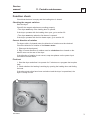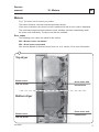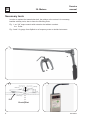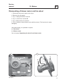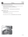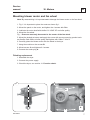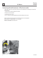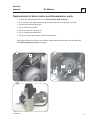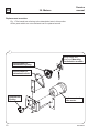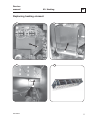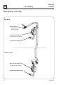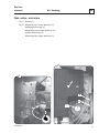
1
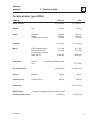
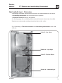
SERVICE MANUAL
T4300S, TD30x30
487 03 29 81.02
EN
WARNING
WARNING: For your safety the information
in this manual must be followed to minimize
the risk of fire or explosion or to prevent
property damage, personal injury or death.
– Do not store or use gasoline or other flammable
vapors and liquids in the vicinity of this or any
other appliance.
– WHAT TO DO IF YOU SMELL GAS:
• Do not try to light any appliance.
• Do not touch any electrical switch; do not use
any phone in your building.
• Clear the room, building or area of all
occupants.
• Immediately call your gas supplier from a
neighbor’s phone. Follow the gas supplier’s
instructions.
• If you cannot reach your gas supplier, call the
fire department.
– Installation and service must be performed by
a qualified and authorized installer, service
agency or the gas supplier.
2
487 0329 81
Service
manual
Overview
Service
Instruction
Machine
units and
components
Safety rules
1
Technical data
2
Description of principal components
3
Periodic maintenance
11
Controls
21
Sensors and overheating thermostats
27
Door and lint drawer
29
Motors - drum and blower
30
Heating
40
Machine Access
41
Drum with bearing
42
Pressure switch
46
4
487 0329 81
Service
manual
1. Safety rules
1
Safety rules
This machine is only intended for drying water-washed garments.
Clothes that have been cleaned with chemicals/flammable liquids, must
NOT be dried in the machine.
Remove clothes from the tumble dryer as soon as they are dry.
This prevents them from becoming creased, and reduces the risk of
spontaneous ignition.
The machine must not be used for drying foam rubber or foam-like
materials.
The machine must not be used for drying floor mops.
(This applies only to floor mops containing polypropylene).
The machine must not be used by children.
The machine must not be hosed down with water.
Mechanical, electrical and gas installations must only be carried out by
qualified, licensed personnel.
Report machine malfunctions to qualified service personnel immediately.
This is important for your own safety and for the safety of others.
Gas dryers only:
The machine is not to be installed in rooms containing cleaning
machines with PERCHLORETHYLENE, TRICHLOROETHYLENE or
CHLOROFLUOROCONTAINING HYDROCARBONS as cleaning agents.
What to do if you smell gas:
Do not try to light any appliance.
Do not touch any electrical switch; do not use any phone in your building.
Evacuate the room, building or area.
Contact appropriate authorities.
Servicing the dryer
Refer servicing to qualified personnel.
Improper servicing can result in hazardous conditions, fire, explosion,
property damage, and personal injury.
Some components may have sharp edges!
Wear gloves when handling mechanical components.
487 0329 81
1
Service
manual
2
487 0329 81
Service
manual
2. Technical data
2
Contents
Technical data type 4300S . . . . . . . . . . . . . . . . . . . . . . . . . . . . . . . . . . 2.3
Technical data type TD30x30 - gas heating . . . . . . . . . . . . . . . . . . . . . 2.4
487 0329 81
1
2
487 0329 81
Service
manual
2
2. Technical data
Technical data, type 4300S
Heating
Drum volume:
Weight:
Net
Drum:
Diameter
Depth
Revolutions per minute
Capacity:
Motor:
Heat effect:
Effect without reverse
Effect with reverse
Revolutions per minute
Motor 50 Hz
Motor 60 Hz
Electric
Gas
Air consumption:
Piping:
Exhaust
Pressure drop:
Exhaust (max.)
Electric
Gas
2 x 300 litres
2 x 300 litres
282 kg
282 kg
760 mm
660 mm
45 rpm
760 mm
660 mm
45 rpm
2 x 13.6 kg
2 x 13.6 kg
2 x 1 kW
2 x 1 kW
2 x 1 kW
2 x 1 kW
2700 rpm
3200 rpm
2700 rpm
3200 rpm
2x9 kW/2x13.5 kW/2x18 kW
2 x 21 kW
2 x 600 m3/h
2 x 600 m3/h
Ø 200
Ø 200
400 Pa
400 Pa
ISO 7/1-R1/2
Gas piping:
Gas pressure:
Sound pressure level:
487 0329 81
See page regarding pressure section 40 Gas
< 70 dB (A)
< 70 dB (A)
3
2
Service
manual
2. Technical data
Technical data, TD30x30, Gas heating
2 x 10.6 cu.ft.
Drum volume:
Weight:
Net
Cylinder:
Diameter
Depth
Revolutions per minute
620 lb
29 15/16”
26”
45 rpm
2 x 30 lb
Capacity:
Motor single phase:
Effect of vent motor
Effect of cylinder motor
1 x 0.54 hp
1 x 0.7 hp
Revolutions per minute: Motor 60 Hz
3200 rpm
Heat effect:
Gas heating
2 x 71600 BTU/h
Air consumption:
Gas 2x 21 kW
2x353 cu.ft/min
Piping:
Exhaust
Pressure drop:
Exhaust (max.)
ø8”
1.57”W.C
1/2” NPT
Gas piping:
Gas pressure:
Sound pressure level:
4
See page regarding pressure section 40 Gas
< 70 dB (A)
487 0329 81
Service
manual
3. Description of principal components
3
Contents
Glossary . . . . . . . . . . . . . . . . . . . . . . . . . . . . . . . . . . . . . . . . . . . . . . . . . 3.3
Description . . . . . . . . . . . . . . . . . . . . . . . . . . . . . . . . . . . . . . . . . . . . . . . 3.4
487 0329 81
1
2
487 0329 81
Service
manual
3. Description of principal components
3
Glossary
Auto Stop The tumble dryer stops automatically when the clothes are dry.
AHL
Apartment House Laundry - Communal laundries / Housing block laundries.
GN
Natural gas.
LPG
Bottle gas.
OPL
On Premises Laundry - Institutional laundries.
PCB
Printed Circuit Board.
RMC
Residual Moisture Control - The tumble dryer has residual moisture control.
487 0329 81
3
3
3. Description of principal components
Service
manual
Description
Dryer T4300S or TD30x30 is a stack dryer.
The dryer has 2 independent pockets.
Each pocket has a drum volume of
300 litres (10.6 cu.ft).
Motors
The dryer has 2 motors per pocket - one to
run the drum and one to run the blower.
Programs, Selecta Control ver. 4.xx
(Non-Coin version)
Each pocket has an independent operating
panel and an independent PCB.
The dryer’s control provides diagnostic error
codes which offer guidance in troubleshooting.
487 19 24 05.01
487 19 24 05.01
OPL with RMC
On OPL with RMC (non-coin operated) models,
there are nine factory-provided drying programs
in the dryer control memory.
It is also possible to directly select the desired
drying time.
The dryer stops automatically when the clothes
have the chosen residual moisture.
OPL with Auto Stop
On OPL (non-coin operated) models, there are
five factory-provided drying programs in the
dryer control memory.
It is also possible to directly select the desired
drying time.
The dryer stops automatically when the clothes
are dry (Auto Stop).
Coin drop/card reader
The dryer is available with a factory-installed
coin drop, a factory-installed card-start system,
or it can be prepared for field installation of a
card start system. On vending models, insertion
of a coin or card vends an owner- programmed
drying time.
4
487 0329 81
Service
manual
3. Description of principal components
3
Loading door
The dryer is delivered with a right-hinged door or a left-hinged door.
The door is not reversible.
A door switch ensures that the dryer stops automatically if the dryer is opened during the
program sequence, see section 29.
Operating panel
The operating panel is equipped with:
• Buttons for setting programs, temperatures, and drying time.
• Start/stop button.
• Display showing program selection, remaining drying time and error code, if any.
• Heating indicator, lamp lights when heating is on.
Heating
The standard configuration is equipped for natural gas.
An LPG conversion kit is available see section 40.
Use
The dryer is designed for coin-operated laundries or on premises laundries.
487 0329 81
5
Service
manual
6
487 0329 81
Service
manual
11. Periodic maintenance
11
Contents
Function check . . . . . . . . . . . . . . . . . . . . . . . . . . . . . . . . . . . . . . . . . . . 11.3
Maintenance - External parts . . . . . . . . . . . . . . . . . . . . . . . . . . . . . . . . 11.4
Maintenance - Internal wearing parts . . . . . . . . . . . . . . . . . . . . . . . . . . 11.7
The area surrounding the dryer . . . . . . . . . . . . . . . . . . . . . . . . . . . . . 11.10
Safety and warnings signs (US only) . . . . . . . . . . . . . . . . . . . . . . . . . 11.10
487 0329 81
1
2
487 0329 81
Service
manual
11. Periodic maintenance
11
Function check
Check that the drum is empty and the loading door is closed.
Checking the magnet switches
Start the dryer.
Check if the magnet switches are working properly:
• The dryer must stop if the loading door is opened.
If the dryer operates with the loading door open, go to section 29.
• The dryer must stop when the lint drawer is opened.
If the dryer operates with the lint drawer open, go to section 29.
Correct direction of rotation
For dryers with a 3-phased motor the direction of rotation must be checked.
Check the direction of rotation of the blower motor:
1. Dismount the back panel.
2. Fig. 1 Correct direction of rotation must be clockwise when viewed on the
blower motor on the rear of the dryer.
If the direction of rotation is not correct, swap two phases on the power input
connection terminal block.
Final test
1. Start the dryer and allow it to operate for 5 minutes on a program that requires
heat.
2. Check whether the heating is working by opening the loading door and feeling
the heat.
If the above test points have been carried out and the dryer is operational, the
dryer is ready for use.
1
487 0329 81
3
11
Service
manual
11. Periodic maintenance
Maintenance
The table below shows the frequency of maintenance of the external parts and the
internal wearing parts.
Frequency
Page
daily
11.5
once a week
11.5
daily
11.6
quarterly
11.6
semi-annually
11.6
Cleaning around the drum
semi-annually
11.7
Exhaust plenum
semi-annually
11.8
Backdraft dampers
semi-annually
11.8
Blower compartment
semi-annually
11.8
Blower wheel
semi-annually
11.8
Gas burner
semi-annually
11.9
every year
11.9
External parts
Lint drawer
Lint drawer tracks
Door gasket
Lifters in the drum (RMC only)
Air inlet screen
Internal wearing parts
Control compartment
4
487 0329 81
Service
manual
11
11. Periodic maintenance
Maintenance
Lint drawer
Check (at least once daily) that the lint screen in the drawer is clean and in good
condition.
Clean the drawer in both the top and bottom dryers. Use a vacuum cleaner.
Clean the gasket with a damp cloth. Do not use solvents that may damage sensitive
plastics or painted finish.
Fig 1 and 2 Replace the gasket A by a new one if it is defective. Do not use glue on the
gasket.
Lint drawer tracks
Check with a minimum of once a week the lint drawer tracks.
1. Remove the drawer and clean the tracks with a stiff brush.
Remember to clean the lint drawer tracks in both the top and bottom dryers.
1
2
A
487 0329 81
A
5
11
11. Periodic maintenance
Service
manual
Door gasket
Check at least daily that the loading door gasket is clean and in good condition.
Clean with a damp cloth. Do not use solvents that may damage sensitive plastics or
painted finish.
Lifters in the drum (Dryer with RMC only)
To ensure that the moisture tracing is always working optimally it is important to clean
the lifters.
Lack of cleaning the lifters can reduce the automatic residual moisture control in the
clothes resulting in the clothes being moister than requested when the program has
ended.
Cleaning
Wipe off/clean drum and lifters with citric acid (Acidum citricum). If soap/softener residue
remains, it is recommended also to use a coarse sponge.
The frequency of cleaning should depend on the operating frequency - with a minimum
of once a week.
Air inlet screen
Check every semi-annually that the air inlet screen in the lower back panel has not
become blocked with lint or other debris.
6
487 0329 81
Service
manual
11. Periodic maintenance
11
Maintenance - Internal wearing parts
Maintenance should be conducted to an extent related to operation frequency and the
conditions on the premises, or at least once a semi-annually.
Cleaning around the drum
1. Disconnect the power supply from the dryer.
2. Fig. 1 Dismount the front panel (See section 42: Replacing support rollers).
3. Remove the lint using a vacuum cleaner.
4. Inspect the two support rollers and replace them if necessary.
5. Re-assemble the dryer.
6. Connect the power supply - remember to carry out a function check as described
earlier in this section.
1
Remove all accumulated lint
487 0329 81
7
11
11. Periodic maintenance
Service
manual
Exhaust plenum
Check every semi-annually that the exhaust plenum on the rear of the dryer has not
become blocked with lint or other debris.
Dismounting
1. Dismount both rear panels.
2. Dismount the 4 screw in the top panel to the left-hand side.
3. The exhaust plenum can now be lifting away.
The inside part of the exhaust plenum can be cleaned.
4. Reassemble the dryer.
Back draft dampers
Check every semi-annually the Back draft dampers.
Fig. 1 The back draft dampers is located in the exhaust plenum. To dismount the exhaust
plenum see Exhaust plenum.
Blower compartment
Check every semi-annually that the blower compartment has not become blocked with
lint or other debris.
Dismounting the blower to get to the blower compartment, see section 30.
Blower wheel
Check every semi-annually that the blower wheel has not become blocked with lint or
other debris.
Fig. 2 Dismount the blower motor to get access to the blower wheel to clean,
see section 30.
NOTE Be careful not to damage the blower wheel.
1
8
2
487 0329 81
Service
manual
11. Periodic maintenance
11
Control compartment
Check every year that the control compartment has not become blocked with lint or other
debris.
The control compartment is located behind the rear panel.
1. Disconnect the power supply to the dryer.
2. Remove the back plate.
3. Check the control compartment for dust and carefully vacuum clean if necessary.
4. Reassemble the dryer.
5. Connect the power supply - remember to carry out a function check as described
earlier in this section.
Control of the gas burner
Check every semi-annually that the gas is burning evenly and with a bluish flame.
See test run section 40
487 0329 81
9
11
11. Periodic maintenance
Service
manual
The area surrounding the dryer
Fresh-air intake to the room
Check that the fresh-air intake to the room and the exhaust ducts/pipes from the room
are not clogged by lint/dust or blocked in any other way.
Dryer area
Check that the dryer area is clear and free from combustible materials, gasoline and
other flammable vapours and liquids.
Safety and warnings signs (US and Australia only)
Product safety signs or labels should be replaced when they no longer meet the legibility
requirements for safe viewing.
Check that all the safety and warning signs are located on the dryer as shown in the
installation manual supplied with the dryer. A copy of this manual is available from your
dealer.
Replacement of safety signs or labels should be in accordance with the installation
manual.
10
487 0329 81
Service
manual
21. Controls
21
Contents
Printed circuit board . . . . . . . . . . . . . . . . . . . . . . . . . . . . . . . . . . . . . . . 21.3
Connecting accessory systems . . . . . . . . . . . . . . . . . . . . . . . . . . . . . . 21.3
Connection to network . . . . . . . . . . . . . . . . . . . . . . . . . . . . . . . . . . . . . 21.4
Programming. . . . . . . . . . . . . . . . . . . . . . . . . . . . . . . . . . . . . . . . . . . . . 21.5
Replacement of PCB . . . . . . . . . . . . . . . . . . . . . . . . . . . . . . . . . . . . . . 21.6
Circuit boards MUST be protected
from static electricity!
Remember!
• Always use an earthed wrist strap.
• Without the antistatic wrapping, the board is unprotected.
• Keep all items that can cause static discharge (such as plastic bags,
fabric, and the like) away from the circuit board.
• Items like plastic, foam plastic, nylon, or cellophane wrapping are all big
generators of static electricity.
• Static electricity can not be felt, heard or seen till the voltage reaches
2500V.
• Board components can be damaged by static electricity under 100V.
487 0329 81
1
2
487 0329 81
Service
manual
21
21. Controls
Printed circuit board
The PCB is placed behind the operating panels to the left and right side of the top lint
drawer, fig. 1.
The PCB contains a board with display, indicator lamps.
The PCB contains a button A for Switching to Programming mode,
see section 3: Description in Service Manual for Selecta II Control
The PCB contains a button B for gas reset (Only activated on gas dryer) see later in this
section.
Connecting accessory systems
Different payment systems can be connected to the PCB,
see section 41: Machine Access
1
PCB to bottom
dryer
487 0329 81
PCB to top dryer
3
21
Service
manual
21. Controls
Connection to network
Fig. 1 If several dryers are to be connected to a network a bushing for network cables
are installed in the both side panels of the dryer. See the installation manual enclosed
the dryer.
1. Disconnect the power supply.
2. Remove the lint drawer.
3. Unscrew the 2 screws and remove the cover.
4. Pull the network cable through the bushing and connect the cable to the PCB.
5. The network cable can now be installed.
6. After installing mount the cover again.
1
2
B
A
4
487 0329 81
Service
manual
21. Controls
21
Programming
To enter the programming mode press service button A.
After pressing the service button A the display shows:
0 -- = Group 0.
Program the dryer, see Service Manual for Selecta Control from ver. 4.xx for
programming details.
Gas reset button
The button B is the gas reset button.
See Section 40: Heating, gas.
High voltage on the printed circuit board
Do not touch the printed circuit board.
The shaded areas indicate high voltage.
A
487 0329 81
B
5
21
21. Controls
Service
manual
Replacement of PCB
The PCB is not serviceable. It must be replaced if it fails.
The PCB can be ordered as a spare part.
The spare part consists of: Printed circuit board with fuses in anti-static packing and
instructions.
The PCB Selecta Control software from version 4.01 is pre-programmed with specific features
and may need to be “post-programmed” after installation.
Installation
1. Disconnect the power supply to the dryer.
2. Open the operating panel to the defected print board. (See earlier in this section).
3. Remove the defected print board, but keep the 5 nuts for later use.
4. Mount the new print board from the kit.
5. Mount the nuts where shown and tighten.
Follow the instructions from the kit when programming.
Following settings have to be programmed:
• Reversing (Yes or No). (Parameter 4 01).
• Heating type. (Parameter 4 02).
• Payment settings (Time per coin, standby display value, display flashing). (Parameter 4 03).
• Panel type. (Parameter 4 04).
• Program type. (Parameter 4 05).
6
487 0329 81
Service
manual
21. Controls
21
Service Manual for Selecta Control software version from 4.01
Certain parameters need to be set after installation, according to the characteristics of
the dryer and the preferences of the owner.
See Service Manual for Selecta Control software version from version 4.xx for further
details.
487 0329 81
7
Service
manual
8
487 0329 81
Service
manual
27. Sensors and overheating thermostats
27
Contents
Gas heated dryer - Overview . . . . . . . . . . . . . . . . . . . . . . . . . . . . . .27.3
Inlet air:
Overheating thermostat. . . . . . . . . . . . . . . . . . . . . . . . . . . . . . . . . . .27.4
Thermistor element . . . . . . . . . . . . . . . . . . . . . . . . . . . . . . . . . . . . .27.5
Replacing / resetting . . . . . . . . . . . . . . . . . . . . . . . . . . . . . . . . . . . . .27.6
Outlet air:
Overheating thermostat . . . . . . . . . . . . . . . . . . . . . . . . . . . . . . . . . .27.7
Thermistor element . . . . . . . . . . . . . . . . . . . . . . . . . . . . . . . . . . . . .27.8
Replacing / resetting . . . . . . . . . . . . . . . . . . . . . . . . . . . . . . . . . . . . .27.9
487 0329 81
1
2
487 0329 81
Service
manual
27. Sensors and overheating thermostats
27
Gas heated dryer - Overview
Overheating thermostats and thermistor elements are located behind the rear panels.
• Overheating thermostats can be manual reset or replaced.
• Thermistor elements can only be replaced.
On following pages the overheating thermostat and thermistor element are described.
Replacement and manual resetting is described later in this section.
Fig.1 Positioning of Thermistor elements and Overheating thermostats in inlet- and
outlet air.
1
Inlet air - top dryer
Outlet air - top dryer
Inlet air - bottom dryer
Outlet air - bottom dryer
487 0329 81
3
27
27. Sensors and overheating thermostats
Service
manual
Inlet air - Overheating thermostat
Function
The inlet overheating thermostat opens in the event of overheating, and shuts off the
dryer.
The thermostat has to be reset manually.
Error code
The following error code is related to this section.
E08
See Service Manual for Selecta Control from ver. 4.xx, section 12 for more information.
Overheating
thermostat
4
487 0329 81
Service
manual
27. Sensors and overheating thermostats
27
Inlet air - Thermistor element (PT100 sensor)
Function
The thermistor element measures the temperature of the heated air entering the drum.
The resistance of this device is normally 110 Ohms at 20°C (68°F) and increases as the
temperature rises.
The signal is returned to the PCB and this ensures that the inlet air does not become
excessively hot, thus preventing scorching of garments.
Error codes
The following error codes are related to this section:
E03, E17
See Service Manual for Selecta Control from ver. 4.xx, section 12 for more information.
Thermistor
element
487 0329 81
5
27
Service
manual
27. Sensors and overheating thermostats
Inlet air - Overheating thermostat and thermistor element
In order to replace
1. Fig. 1 Disconnect the power supply.
2. Remove the top rear panel.
3. Loosen wires A.
4. Remove wires at points B.
5. Remove screws C and pull out the panel.
Now the overheating thermostat or the thermistor element can now be replaced.
In order to reset the thermostat
1. Fig. 1 Disconnect the power supply.
2. Remove the back panels.
3. Reset on button D.
Replacing the overheating thermostat
1. Remove 2 screws.
Replacing the thermistor element
1. Fig. 2 Mount the element as shown.
After replacement / resetting
1. Remount the top rear panel and wires
2. Reassemble the dryer.
Function check
Test the dryer see section 11: Function check.
2
1
A
A
20
mm
”
0.8
B
D
C
6
C
487 0329 81
Service
manual
27. Sensors and overheating thermostats
27
Outlet air - Overheating thermostat
Function
The outlet air overheating thermostat is located in the outlet air flow.
The overheating thermostat ensures that the dryer does not overheat during program
operation.
The thermostat opens automatically and has to be reset manually.
Error code
The following error code is related to this section.
E08
See Service Manual for Selecta Control from ver. 4.xx, section 12 for more information.
Overheating thermostat
487 0329 81
7
27
27. Sensors and overheating thermostats
Service
manual
Outlet air - Thermistor element (NTC sensor)
Function
The sensor measures the temperature in the outlet air and the signal is returned to the
main circuit board.
The main circuit board turns the heating unit off when the outlet air thermistor indicates
that the required temperature has been reached.
The resistance of this device is normally 4 to 6 kOhms at 20°C (68F) and it drops as its
temperature increases.
Error codes
The following error codes are related to this section.
E04, E18
See Service Manual for Selecta Control from ver. 4.xx0 , section 12 for more information.
Thermistor
element
8
487 0329 81
Service
manual
27. Sensors and overheating thermostats
27
Outlet air - Overheating thermostat and thermistor element
Replacing overheating thermostat (B)
1. Fig. 1 Disconnect the power supply.
2. Remove the rear panels.
3. Loosen wires A.
4. Remove the 2 screws and replace the thermostat.
In order to reset the thermostat (B)
1. Fig. 1 Disconnect the power supply.
2. Remove the rear panels.
3. Reset on button.
Replacing the thermistor element (C)
1. Fig. 1 Remove the element and loosen plug C.
2. Replace sensor.
After replacement / resetting
1. Remount wires.
2. Reassemble the dryer.
Function check
Test the dryer see section 11: Function check.
1
C
A
B
A
487 0329 81
9
Service
manual
10
487 0329 81
Service
manual
29. Door and lint drawer
29
Contents
Loading door magnet switch . . . . . . . . . . . . . . . . . . . . . . . . . . . . . .29.3
Testing door lock on loading door . . . . . . . . . . . . . . . . . . . . . . . . . .29.4
Lint drawer magnet switch . . . . . . . . . . . . . . . . . . . . . . . . . . . . . . .29.5
Replacement of rubber packing at front . . . . . . . . . . . . . . . . . . . . .29.6
487 0329 81
1
2
487 0329 81
Service
manual
29. Door and lint drawer
29
Loading door magnet switch
Fig. 1 A magnet switch A is mounted below the snap catch at the loading door.
Fig. 2 A magnet B is mounted on the loading door under the snap lock.
The switch ensures that the dryer stops automatically if the loading door is opened
during operation.
If the dryer does not stop when the loading door is opened, following has to be checked
After replacement
1. Reassemble and test, as follows:
2. Connect the power supply.
3. Start the dryer.
4. Check that the fan, drum and heat all stop when the loading door is opened.
1
2
B
A
487 0329 81
3
29
29. Door and lint drawer
Service
manual
Testing door lock on loading door
It must be possible to open the door lock on the loading door from the inside with a force
not exceeding 70N (7,1Kp).
The door must be strained with a force corresponding to the above 70N (7,1Kp).
The strain must be done as far from the door hinge as possible.
Fig. 1 The lock is adjustable.
1
4
487 0329 81
Service
manual
29. Door and lint drawer
29
Lint drawer magnet switch
Function
The lint drawer magnet switch ensures that the dryer will not operate when the drawer is
open.
If the dryer does not operate with the lint drawer closed, the lint drawer switch may need
to be replaced.
Replacement
1. Disconnect the power supply.
2. Remove the lint drawer.
3. Open the left operating panel.
4. Unscrew the 2 nuts and remove the cover A.
5. Disconnect the wires from the switch.
6. Mount the new switch.
7. Connect wires to the new switch.
8. Remount the cover with the new switch.
Testing the lint drawer switch
1. Connect the power supply.
2. Start the dryer.
3. Confirm that the fan, drum and heat all stops when the lint drawer is opened while the
dryer is operating.
1
A
487 0329 81
5
29
29. Door and lint drawer
Service
manual
Replacement of rubber packing at the front
Inspect the rubber packing at the front and if necessary remove and replace it.
Clean any residual adhesive from the panel before installing a new packing.
Shown at fig 1.
1
5
9.
cm
6
487 0329 81
Service
manual
30. Motors
30
Contents
Motors . . . . . . . . . . . . . . . . . . . . . . . . . . . . . . . . . . . . . . . . . . . . . . . . . . 30.3
Necessary tools. . . . . . . . . . . . . . . . . . . . . . . . . . . . . . . . . . . . . . . . . . . 30.4
Dismounting of blower motor and fan wheel . . . . . . . . . . . . . . . . . . . . 30.5
Mounting blower motor and fan wheel . . . . . . . . . . . . . . . . . . . . . . . . . 30.7
Loosening the belt tensioner of the drum motor . . . . . . . . . . . . . . . . . . 30.8
Replacement of drum motor and transmission parts . . . . . . . . . . . . . . 30.9
Replacement of transmission belt. . . . . . . . . . . . . . . . . . . . . . . . . . . . 30.11
Replacement of transmission pulley . . . . . . . . . . . . . . . . . . . . . . . . . . 30.12
Replacement of drum motor or pulley. . . . . . . . . . . . . . . . . . . . . . . . . 30.13
487 0329 81
1
2
487 0329 81
Service
manual
30
30. Motors
Motors
Fig 1 The dryer has 2 motors per pocket.
The motors features a thermal overheat protection device.
If the motor overheats, the control current is switched off and an error code is displayed.
The overheat protection switch inside the motor windings recloses automatically when
the motor cools sufficiently. The dryer can then be restarted.
Error codes
The following error codes are related to the motors:
E05 = Blower motor overheated
E06 = Drum motor overheated
See Service Manual for Selecta Control from ver. 4.xx, section 12 for more information.
1
Top dryer
Blower motor
with fan wheel
Drum motor with
transmission
Bottom dryer
Drum motor with
Blower motor
transmission
with fan wheel
487 0329 81
3
30
Service
manual
30. Motors
Necessary tools
In order to replace the transmission belt, the pulleys or the motors it is necessary,
besides ordinary tools, also to have the following tools:
Fig. 1 a = 3/8” torque wrench with extension but without a socket.
b = Puller
Fig. 2 and 3 A gauge from Optibelt or a frequency meter or similar instrument.
1
a
b
2
3
Belt
Check point
4
487 0329 81
Service
manual
30
30. Motors
Dismounting of blower motor and fan wheel
1. Disconnect the power supply to the dryer.
2. Remove the rear panels.
3. Fig. 1 Unplug the blower motor A.
4. Fig. 1 Loosen the 2 screws B.
5. Fig. 1 Dismount the 2 screws C.
6. Fig. 2 Carefully release blower motor with fan wheel. (The fan wheel is easily
damaged).
After dismounting, it is possible to replace:
a = Fan wheel.
b = Blower motor.
See next page: Separating fan wheel from blower motor
2
1
a
B
b
A
C
487 0329 81
5
30
30. Motors
Service
manual
Separating fan wheel from blower motor
1. Dismount the slotted set screw from the shaft, you can get access to the set screw
through a hole in one of the blades, see principle fig.1.
2. Carefully release the fan of the motor shaft using a puller.
3. Replace the fan wheel.
If the replacement is done see: Mounting blower motor and fan wheel
Replacing blower motor
1. Unscrew the 4 screws in the panel which secure the blower motor.
2. Remove the panel.
3. The blower motor can now be replaced.
After replacing the blower motor see: Mounting blower motor and fan wheel.
1
6
487 0329 81
Service
manual
30
30. Motors
Mounting blower motor and fan wheel
Note! By reassembling it is important not to damage the blower motor or the fan wheel.
1. Fig. 1 It is important to place the motor as shown fig 1.
2. Mount the panel on the motor, and tighten the 4 screws with 5Nm.
3. Lubricate the motor shaft with Antifret G1 LGAF 3E or similar quality.
4. Mount the fan wheel.
Fig. 1 Pressure must only be exerted to the center of the fan wheel.
5. Mount the slotted set screw and apply the screw with a screw securing product such
as Omnifet Seal 40M or similar quality and tighten with 10Nm/ 7.4 lbf ft.
6. Carefully place the blower motor with fan wheel in the dryer.
7. Hang the module on the screws B.
8. Mount screws C and tighten all 4 screws.
9. Connect the motor plug A.
Finishing replacement
1. Assemble the dryer.
2. Connect the power supply.
3. Check the dryer, see section 11: Function check.
1
2
B
A
CL
487 0329 81
C
7
30
30. Motors
Service
manual
Loosening the belt tensioner of the drum motor
If the drum, drum belt or the drum motor has to be replaced it is necessary to loosen the
belt tensioner.
1. Disconnect the power supply to the dryer.
2. Remove the rear panels.
3. Unplug the drum motor.
4. Fig. 1 Loosen the spring holder A at the belt tensioner, see arrow.
After loosening the belt tensioner the following items can be replaced:
Drum motor or transmission, see next pages
Drum or drum belt, see section 42.
1
A
8
487 0329 81
Service
manual
30
30. Motors
Replacement of drum motor and transmission parts
1. Loosen the transmission belt, see: Loosening the belt tensioner
2. Fig.1 Remove the spring holder A at the belt tensioner, the spring is released.
3. Lift the drum belt off the pulley.
4. Fig. 2 Remove screw B
5. Fig. 2 Loosen the 2 screws C.
6. Fig. 2 Remove the bracket D.
7. Fig. 3 Lift off the drum motor and the transmission.
After dismounting the drum motor and the transmission several items can be replaced,
see Replacement overview next page.
2
1
A
D
C
B
3
487 0329 81
9
30
Service
manual
30. Motors
Replacement overview
Fig. 1 The boxed text referring to the description later in this section
All the parts which are not mentioned can be replaced as well.
1
Spring holder and
spring see Mounting
transmission module
Replacement of
transmission pulley
Replacement of
transmission belt
Replacement
of pulley
10
Replacement of
drum motor
487 0329 81
Service
manual
30
30. Motors
Replacement of transmission belt
1. Dismount the transmission module, see section: Replacement of drum motor and
transmission parts
2. Fig. 1 Loosen the 2 nuts A.
3. Remove the old belt.
4. Fig. 1 Push the new belt through the hole B. Remember to turn the belt so that the
tracks are facing the pulley.
5. Pull the belt over the transmission bearing.
6. Fig. 2 Put a screw driver through the hole C and into the opposite hole.
7. Press the screw driver upwards.
8. Tighten the belt to 225 ±25Hz / 65N.
If the replacement is done see section Mounting the drum motor and the
transmission.
1
2
C
B
A
487 0329 81
11
30
Service
manual
30. Motors
Replacement of transmission pulley
1. Dismount the transmission module see section: Replacement of drum motor and
transmission parts
2. Fig 1 Remove the 2 nuts A.
3. Fig. 2 Remove the retaining ring C and 1 washer at B.
5. Pull the pulley B off and replace.
6. Mount the washer and the retaining ring.
7. Mount the bracket and the two nuts - do not tighten the nuts too much.
8. Put the transmission belt around the pulley.
9. Tighten the belt, see Replacement of belt
10. Fig. 1 Tighten the 2 nuts A with 30NM.
If the replacement is done see section Mounting the drum motor and the transmission.
1
2
B
C
B
A
12
487 0329 81
Service
manual
30. Motors
30
Replacement of drum motor or pulley
1. Loosen the transmission belt, see Replacement of transmission belt
2. Fig. 1 Dismount the 2 slotted set screws A in pulley.
3. Fig. 2 Pull off the pulley, use a puller.
4. Before mounting the pulley it is important to lubricate the motor shaft with anti-fretting
paste G1 LGAF 3E or similar quality.
5. Replace the drum motor or the pulley.
Pressure must only be exerted to the center of the motor.
See the principle fig. 1 Mounting blower and fan wheel.
6. Apply the 2 slotted set screws with a screw securing product such as Omnifit Seal
40M or similar quality.
7. Put the transmission belt around the transmission pulley.
8. Tighten the belt, see Replacement of transmission belt
9. Fig. 1 Tighten the 2 nuts C with 30NM.
After replacement see next page: Mounting the drum motor and the transmission.
1
2
A
B
C
487 0329 81
13
30
Service
manual
30. Motors
Mounting the drum motor and the transmission
1. Mount the transmission module in the dryer.
2. Fig. 1 Mount bracket D and screw B and tighten all screws B+C.
3. Put the drum belt around the pulley.
Note! It is important to fit the belt at the right place of the pulley.
The small diameter of the pulley is used for 60 Hz.
The large diameter of the pulley is used for 50 Hz.
4. Fig. 2 Mount the bracket A on the shaft of the pulley.
5. Mount the spring in the spring holder.
6. Tighten the belt tensioner reverse order of loosening the belt.
Finishing replacement
1. Assemble the dryer.
2. Connect the power supply.
3. Check the dryer, see section 11: Function check.
1
2
A
D
C
14
B
487 0329 81
Service
manual
40. Heating
40
Contents
Electric heated dryer
Heating unit types . . . . . . . . . . . . . . . . . . . . . . . . . . . . . . . . . . . . . . . . . 40.3
Before replacement. . . . . . . . . . . . . . . . . . . . . . . . . . . . . . . . . . . . . . . . 40.4
Replacing heating unit . . . . . . . . . . . . . . . . . . . . . . . . . . . . . . . . . . . . . 40.5
Gas heated dryer
Gas heating unit, overview . . . . . . . . . . . . . . . . . . . . . . . . . . . . . . . . . . 40.7
Gas system, overview. . . . . . . . . . . . . . . . . . . . . . . . . . . . . . . . . . . . . . 40.8
Gas valve, overview . . . . . . . . . . . . . . . . . . . . . . . . . . . . . . . . . . . . . . . 40.9
Gas valve, nozzle pressure. . . . . . . . . . . . . . . . . . . . . . . . . . . . . . . . . 40.10
Gas valve, supply pressure. . . . . . . . . . . . . . . . . . . . . . . . . . . . . . . . . 40.11
Tables of pressure and adjustments . . . . . . . . . . . . . . . . . . . . . . . . . . 40.12
Replacement of gas burner tube . . . . . . . . . . . . . . . . . . . . . . . . . . . . 40.14
Adjustment of ignition electrode . . . . . . . . . . . . . . . . . . . . . . . . . . . . . 40.15
Control measuring the ionisation current . . . . . . . . . . . . . . . . . . . . . . 40.15
Resetting gas error . . . . . . . . . . . . . . . . . . . . . . . . . . . . . . . . . . . . . . . 40.15
Replacement of gas valve. . . . . . . . . . . . . . . . . . . . . . . . . . . . . . . . . . 40.16
Conversion to another type of gas . . . . . . . . . . . . . . . . . . . . . . . . . . . 40.18
Test run . . . . . . . . . . . . . . . . . . . . . . . . . . . . . . . . . . . . . . . . . . . . . . . 40.19
WARNING !
FIRE AND / OR EXPLOSION HAZARD!
Gas heating system service procedures
must be carried out by qualified
service personnel!
DO NOT OPERATE THIS MACHINE WITH IMPROPER SUPPLY OR NOZZLE
PRESSURES, AS THIS CAN CAUSE FIRE AND/OR EXPLOSION!
Improper installation, adjustment or operation of this gas-heated appliance may
result in the risk of fire and/or explosion, damage to property, serious injury, or
death.
487 0329 81
1
2
487 0329 81
Service
manual
40. Heating
40
Electric heated dryer
Description
The heating units are placed behind the back plates of the dryer.
The heating units have 2 or 3 heating elements depending on voltage and effect.
Heating unit types
Heating effect
Voltage
Number of elements
2x9 kW
230V
2 + 1 dummy
2x9 kW
400 - 480V
2 + 1 dummy
2x13.5 kW
400 - 480V
3
2x18 kW
400 - 480V
3
Spare part number, effect, and voltage are printed on the heating elements.
Before replacement
1. Check that effect and voltage on the new elements are corresponding with
the old ones.
2. Mark up the heating element wires.
Note! It is important to mount the dummy correctly on a 9 kW dryer. It must be placed
closest to the drum.
487 0329 81
3
40
40. Heating
Service
manual
Replacing heating element
If the heating elements are to be replaced it is unnecessary to dismount the whole
heating unit.
Dismounting
1. Switch off the power to the dryer.
2. Dismount outer back plates:
Top dryer: only remove the top back plate
Bottom dryer: remove both back plates
3. Dismount heating box back plates:
Top dryer: Dismount the bottom back plate A, Fig 1
Bottom dryer: Dismount the back plate B, Fig. 2.
4. Top dryer: Dismount the fitting C, Fig. 3.
5. Dismount all wires.
6. Remove the heating elements, FIg 4.
7. Mount the new heating elements.
8. Mount all wires as before, see diagram supplied with the dryer.
Refer to the pictures on the following page.
Finishing replacement
1. Re-assemble the dryer.
2. Connect the power supply.
Function check
Test the dryer, see section 11: Function check.
4
487 0329 81
Service
manual
40
40. Heating
Replacing heating element
1
2
A
B
4
3
C
487 0329 81
5
Service
manual
6
487 0329 81
Service
manual
40
40. Heating
Gas heating unit, overview
Description
The gas heating unit for top or bottom dryer contains a gas burner, see fig. 1.
The gas system contains gas valve, control box and nozzle for top or bottom dryer, see
overview next page.
The gas system and heating units are located at the back of the dryer.
1
Top dryer
Valve and control box
Top dryer
Gas heating unit
Bottom dryer
Valve and control box
Bottom dryer
Gas heating unit
487 0329 81
7
40
40. Heating
Service
manual
Gas system, overview
Top dryer
Shut off valve
Connected to
the gas supply
Gas valve top dryer
Control box not shown
Nozzle to top dryer
Bottom dryer
Gas valve bottom dryer
Control box not shown
Nozzle to bottom dryer
8
487 0329 81
Service
manual
40
40. Heating
Gas valve, overview
Fig. 1: Nozzle (1)
Fig. 2: Measuring tap, nozzle pressure (2)
Adjusting screw cap (3)
Adjusting screw, nozzle pressure (4)
Ignition control box (5)
Measuring tap, supply pressure (6)
2
1
5
6
2
3+4
1
487 0329 81
9
40
40. Heating
Service
manual
Gas valve, nozzle pressure
The numbers in brackets refer to the page regarding the gas valve.
Nozzle (1)
The nozzle orifice size must be correct for the type of gas being used.
The nozzle orifice size must be correct for the installation altitude (US and Canada only).
Refer to the Tables of pressure and adjustments to determine proper orifice size.
Measuring tap, nozzle pressure (2)
1. With the dryer off, loosen the gas pressure tap (2) one-quarter of a turn and connect a
manometer to the tap.
2. Start the dryer with High heat selected.
After a few seconds, the ignition control will energise the gas valve.
Check that the nozzle pressure reading on the manometer is within the allowable range
for the gas type being used, specified in the tables later in this section .
Too high or too low nozzle pressure
If the nozzle pressure is too high or low, adjust it by removing the cap (3) and turning the
screw (4) beneath this cap until the nozzle pressure is correct.
Clockwise = higher pressure.
Counter-clockwise = lower pressure.
Too low nozzle pressure
If the nozzle pressure is still too low, it may be due to limited gas flow (and pressure) on
the supply side of the valve.
1. Close the nozzle pressure measuring tap ( 2) and measure the supply pressure tap.
Continue next page: Supply pressure
10
487 0329 81
Service
manual
40. Heating
40
Gas valve, supply pressure
Measuring tap, supply pressure ( 6)
1. Turn off the manual gas valve to the machine and the dryer started on High heat.
2. Loosen the gas pressure tap ( 6) one-quarter of a turn and connect a manometer to
the tap.
3. Fig. 1 Turn on the manual gas supply valve A.
4. Start the dryer on High heat and check that the supply pressure is within the allowable
range.
Note: If the pressure is not within the range specified in the Tables of pressure and
adjustments:
DO NOT OPERATE THE DRYER. Contact your gas supplier.
NOTE that the gas supply MUST be turned off before loosening tap pos. 6 (SUPPLY)
or gas will escape.
1
A
487 0329 81
11
40
Service
manual
40. Heating
Tables of pressure and adjustments, Except US and Canada
Heat effect: 2 x 21kW
a
c
b
Denmark
Norway
Sveden
Finland
Italy
England
Spain
Portugal
Ireland
Greece
France
Belgium
mm
LPG
GNH
30
20
30
10.5
2.20
3.80
LPG
GNH
28 / 37
20
28 / 37
10.5
2.20
3.80
LPG
GN
28 / 37
20 / 25
28 / 37
20 / 25
2.20
3.30
Germany
LPG
GNH
GNL
30 , 50
20
20
30
10.5
15.5
2.20
3.80
3.80
Holland
LPG
30
30
2.20
GNL
25
15.5
3.80
LPG
GNH
50
20
30
10.5
2.20
3.80
LPG
Propane
GN
30
30
2.20
30
18
18
30
10.5
15.2
2.20
3.80
3.80
Austria
Japan
Australia
New Zealand
The rest of
the world
except: USA
12
d
mbar
mbar
LPG
GNH
GNL
a
Gas type
c Nozzle pressure
b
Connection pressure
d Nozzle
487 0329 81
Service
manual
40
40. Heating
Tables of pressure and adjustments, US and Canada only
Heat effect: 2 x 21kW
Propane gas
Gas pressure
Altitude
Heat effect Heat effect Upper
Inlet
per pocket
total
calorific
MJ/m3 Min. Nom. Max.
Btu/h
Btu/h
Dim.
Nozzle pressure Nozzle
Measuring tap (2)
Inch W.C
mm
71600
143200
93.7
10
11
13
11
2.4
2000 - 3999 ft. 71600
143200
93.7
10
11
13
11
2.3
4000 - 5999 ft.
71600
143200
93.7
10
11
13
11
2.2
6000 - 8000 ft.
71600
143200
93.7
10
11
13
11
2.1
0 - 1999 ft.
Natural gas
Gas pressure
Altitude
Nozzle pressure
Heat effect Heat effect Upper
Inlet
Measuring tap (2)
per pocket
total
calorific
Inch W.C
MJ/m3 Min. Nom. Max.
Btu/h
Btu/h
Dim.
Nozzle
mm
71600
143200
37.78
6
7
10
4.2
3.8
2000 - 3999 ft. 71600
143200
37.78
6
7
10
4.2
3.7
4000 - 5999 ft.
71600
143200
37.78
6
7
10
4.2
3.6
6000 - 8000 ft.
71600
143200
37.78
6
7
10
4.2
3.4
0 - 1999 ft.
487 0329 81
13
40
Service
manual
40. Heating
Replacement of gas burner tube
Dismounting
The gas burner can be replaced without dismounting the gas unit.
1. Shut off the manual valve at the back of the dryer.
2. Disconnect the electrical power supply.
3. Dismount the back panels on the dryer.
4. Unscrew 12 screws in the back panel on the defected gas heating unit.
5. Remove the panel
6. Fig. 1 Unscrew 2 nuts and washers A.
7. Push the burner to point B.
8. Lift the burner free, be careful not to bend the ignition electrode.
Mounting
1. Mount the new burner.
2. Mount screws A and B.
3. Check the distance from the electrode to the burner, see later in this section.
4. Mount the back panel of the heating unit.
5. Mount the back panels of the dryer.
Test run
Before operating the dryer with heat on, test the dryer, see later in this section.
Function check
Test the dryer, see section 11: Function check.
1
2
A
14
B
487 0329 81
Service
manual
40
40. Heating
Adjustment / measuring
Adjustment of ignition electrode
Fig. 1 Illustrates proper ignition electrode adjustment.
The distance from the electrode to the burner tube a must be 5 mm (13/ 64 inch).
The spark gab b must be 2.5 mm (0.1 inch).
Control measuring the ionisation current
1. Fig. 2 Dismount wire with quick connector A
2. Measure the current between the quick connector and the ionisation connector.
The current must be at least 0,9 μA DC.
Resetting gas error
When the ignition control fails to detect a flame a error code E14 is displayed.
When this condition occurs, the gas valve is shut off and the ignition control must be
reset manually.
Resetting
Open the operating panel and press the gas reset button on the back of the user module
board for one second.
See the picture of the gas reset button section 21
NOTE! When resetting the system the dryer must operate on a program with heat and
when the heat indicator is on.
Error code
Error code 14 is a normal occurrence when first starting up a dryer, since air in the gas
line must be purged.
If the problem persists, refer to Service Manual Selecta Control ver. 4.xx section 12
Error code 14 for more information.
1
a
2
A
b
487 0329 81
15
40
40. Heating
Service
manual
Replacement of gas valve
To replace the gas valve follow the procedure below:
1. Shut off the manual valve at the back of the dryer.
2. Disconnect the electrical power supply.
3. Dismount the back panels on the dryer.
4. Fig. 1. Unscrew screw A from the control box.
5. Pull the control box out of the valve.
6. Fig. 2 or fig. 3. Take the union joint B1 = top dryer or B2 = bottom dryer apart.
7. Fig. 4. Remove the screw C on the side of the nozzle retaining plate.
8. Pull the retaining plate toward the rear of the dryer to release gas pipe with
nozzle.
9. Remove nozzle and keep it for later mounting.
10. Replace the valve.
11. Remount nozzle.
12. Tighten the union joint B1 or B2 (50Nm).
13. The nozzle retaining plate must be pushed back in the right position and firmly be
secured with the screw C.
14. Push the control box back into place. Be careful not to bend the terminals.
15. Install the control box retaining screw removed in step 4.
Testing for leaks
After replacement all the joints which were taken apart have to be leak tested.
Use approved leak testing materials and techniques.
Adjusting the gas valve
The new gas valve has to match the machine.
Adjustment see section earlier in this section.
16
487 0329 81
Service
manual
40
40. Heating
Replacement of gas valve
1
2
B1
A
3
4
B2
C
487 0329 81
17
40
40. Heating
Service
manual
Conversion to another type of gas
All countries except US and Canada
If the machine is to be converted to another type of gas, the gas nozzles must be
replaced.
Referring to the installations manual supplied with the dryer.
US and Canada only
The standard configuration is equipped for natural gas.
If the machine is to be converted to another type of gas, the gas nozzles must be
replaced.
The current nozzles can be ordered separately in a conversion kit.
Contact your dealer, or Wascomat, for the part number of the LP conversion kit
appropriate for your altitude.
The conversion kit contains 2 nozzles as well as instructions.
Follow the instructions supplied with the kit.
18
487 0329 81
Service
manual
40
40. Heating
Test run
1. Test all joints for leaks.
2. Before operating the dryer with heat on, check the supply and nozzle pressures as
described earlier in this section.
3. Fig. 1 Check a + b that the gas is burning evenly and with a bluish flame.
If the above tests points are in order, the dryer is ready for use.
4. Mount the back panels.
1
a = Look through the
hole in the back panel
a
b
b = Look underneath
the gas unit
a
b
487 0329 81
19
Service
manual
20
487 0329 81
Service
manual
41. Machine access
41
Contents
Overview - Connections . . . . . . . . . . . . . . . . . . . . . . . . . . . . . . . . . . . . 41.3
Central Payment Coin. . . . . . . . . . . . . . . . . . . . . . . . . . . . . . . . . . . . . . 41.4
Central Payment Time . . . . . . . . . . . . . . . . . . . . . . . . . . . . . . . . . . . . . 41.5
Coin Meter Single . . . . . . . . . . . . . . . . . . . . . . . . . . . . . . . . . . . . . . . . . 41.6
Coin Meter No Coin Box . . . . . . . . . . . . . . . . . . . . . . . . . . . . . . . . . . . . 41.6
Electrolux Single System . . . . . . . . . . . . . . . . . . . . . . . . . . . . . . . . . . . 41.7
Prepared for Card reader . . . . . . . . . . . . . . . . . . . . . . . . . . . . . . . . . . . 41.7
487 0329 81
1
2
487 0329 81
Service
manual
41. Machine access
41
Overview - Connections
Connection - rear of the dryer
Connection - front of the dryer
487 0329 81
3
41
Service
manual
41. Machine access
Central Payment Coin - CPC
Rear of the dryer
Front of the dryer
PCB
See Service Manual for Selecta
Control from ver. 4.xx
4
487 0329 81
Service
manual
41
41. Machine access
Central Payment Time - CPT
Rear of the dryer
Front of the dryer
PCB
See Service Manual for Selecta
Control from ver. 4.xx
487 0329 81
5
41
41. Machine access
Service
manual
Coin Meter Single - CMS
Coin Meter Single No Box - CMSNB
Front of the dryer
PCB
See Service Manual for Selecta
Control from ver. 4.xx
6
487 0329 81
Service
manual
41. Machine access
41
Electrolux Single System - ESS
Prepared for Card reader - PCR
PCB
See Service Manual for Selecta
Control from ver. 4.xx
487 0329 81
7
Service
manual
8
487 0329 81
Service
manual
42. Drum with bearing
42
Contents
Dismounting of drum/ drum belt . . . . . . . . . . . . . . . . . . . . . . . . . . . . . . 42.3
Replacement of internal sealings . . . . . . . . . . . . . . . . . . . . . . . . . . . . . 42.3
Replacement of drum / drum belt . . . . . . . . . . . . . . . . . . . . . . . . . . . . 42.4
Mounting of drum . . . . . . . . . . . . . . . . . . . . . . . . . . . . . . . . . . . . . . . . . 42.5
Replacing bearing house . . . . . . . . . . . . . . . . . . . . . . . . . . . . . . . . . . . 42.6
Replacement of support rollers . . . . . . . . . . . . . . . . . . . . . . . . . . . . . . 42.7
487 0329 81
1
2
487 0329 81
Service
manual
42
42. Drum with bearing
Dismounting of drum / drum belt
1. Disconnect the power supply to the dryer.
2. Remove the rear panels.
3. Loosen the belt, see Loosening the belt tensioner of the drum motor section 30.
4. Remove the top door hinge.
5. Lift the door off the bottom hinge; remove the bottom hinge.
6. Remove the front panel fastening screws and remove the panel.
7 . Unplug the wire to the door switch.
8. Loosen the fastening nut in the top of the door switch panel and remove the panel with
door switch mounted.
9. Unscrew the 3 screws of the bearing cover and remove the cover.
10. Fig.1 Unscrew and remove bolt and washer from the main drum bearing.
11. Pull out the drum.
The drum, internal sealings or the belt can now be replaced.
Replacement of internal sealings
1. Inspect both sealings A + B and replace if defective.
2. Remove the defected sealing A or B, clean any residual adhesive before installing a
new sealing.
3. Replace the sealing A or B.
4. If replacing sealing A remove the fastening screws in the sealing joint.
The same screws are used to fasten the new sealing.
Note! If seal A has been replaced it is necessary to put a thin coating of silicone oil on
the drum in a distance of 40mm from the perforation for air out. In the position where the
sealing A is running.
1
2
A
B
487 0329 81
3
42
42. Drum with bearing
Service
manual
Replacement of drum / drum belt
1. Replace the belt, if defective.
2. Fig. 1 Hang the belt on 2 of the screws at the back of the drum compartment.
3. Fig. 2 Inspect the felt seals in the drum compartment.
4. Carefully push the drum into the dryer.
Be careful not to damage the felt seal in the drum compartment.
5. Fig. 3 next page Reinstall the bolt and washer into the drum.
Tighten the bolt to 20Nm (15ft lbs)
6. Fig. 4 next page Reinstall the bearing cover A and mount the 3 screws B.
7. Use the hole in the top of the drum compartment to put the belt around the drum.
8. Place the belt around the transmission pulley.
Note! It is important to fit the belt at the right place of the pulley,
see section 30: Mounting the drum motor and the transmission.
9. Rotate the drum manually until the belt is in the proper position on drum and pulley.
10. Tighten the belt, see section 30: Loosening the belt tensioner af the drum motor.
11. Inspect the rubber gasket at the front, see section 29: Replacement of rubber
gasket.
12. Mount the panel with door switch mounted. Fasten the nut in the top of the panel
13 Connect the wire to the door switch.
14. Reassemble the front panel, door hinges, and door.
15. Connect the power supply
Function check
Test the dryer, see section 11: Function check.
1
4
2
487 0329 81
Service
manual
42
42. Drum with bearing
4
3
A
B
20Nm
15 ft-lb
487 0329 81
5
42
Service
manual
42. Drum with bearing
Replacing bearing house
1. Loosening the belt tensioner of the drum motor, see section 30: Motors
1. Fig. 1 Dismount the 3 screws B that secures the bearing house cover.
2. Remove cover A.
3. Unscrew and remove bolt and washer from the main drum bearing
3. Remove the 3 nuts at C.
4. Fig. 2 Remove the bearing house with bearing.
6. Lubricate the shaft with an anti-fretting paste (G1 LGAF 3E or similar quality with a
temperature resistance above 160°C).
7. Fig. 3 and 4 Replace bearing house and bearing. Remember when mounting
new bearing house to mount the 3 Rip lock washers under the nuts with the grooves
upwards.
8. Secure the bearing house by tightening the 3 nuts C with 5Nm and mount cover.
1
2
C
A
B
6
487 0329 81
Service
manual
42. Drum with bearing
42
Replacement of support rollers
1. Disconnect the power to the dryer.
2. Remove the top door hinge.
3. Lift the door off the bottom hinge; remove bottom hinge.
4. Remove the screws that hold the front panel on the dryer and remove the panel.
5. Fig. 1 Unscrew bolts A of the support rollers.
6. Fig. 1 Replace support rollers and tighten bolts A with 20 Nm (15 ft-lb).
7. Reassemble the front panel, door hinges, and door.
8. Connect the power.
Function check
Test the dryer, see section 11: Function check.
2
20 Nm (15 ft-lb)
A
487 0329 81
7
Service
manual
8
487 0329 81
Service
manual
46. Pressure switch
46
Contents
Air pressure switch . . . . . . . . . . . . . . . . . . . . . . . . . . . . . . . . . . . . . . . . 46.3
487 0329 81
1
2
487 0329 81
Service
manual
46. Pressure switch
46
Air pressure switch
Function
The air pressure switch ensures the necessary airflow in the dryer.
Adjustment
The pressure switch is not adjustable. If it fails it has to be replaced.
Error code E15 or E16 general
If the error code E15 or E16 is displayed it is important first to check the under pressure
in the drum compartment. The under pressure that is needed to operate the switch is
90Pa.
Measuring the under pressure in the drum compartment
1. Start the dryer.
2. Remove the rubber tube A and measure the under pressure in the drum compartment.
3. After measuring the under pressure go to the specific error code for further trouble
shooting.
Error code E15
If the under pressure is below 90Pa.
1. Check the rubber tube A for lint-obstruction.
2. See the troubleshooting in the Service Manual Selecta Control from ver. 4.xx section
12 for more information.
Error code E16
Troubleshoot the pressure switch when the dryer is not operating:
1. Check that the normal state for the switch is normally open.
Measure between a (common) and b (NO).
2. If the normal state for the switch is not open check the rubber tube A for lintobstruction.
3. Is there no problem with the rubber tube, see the troubleshooting in the Service
Manual Selecta Control from ver. 4.xx section 12 for more information.
1
a
b
A
487 0329 81
c
3
46
4
46. Pressure switch
Service
manual
487 0329 81