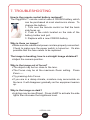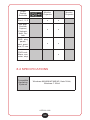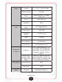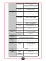
1
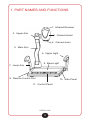
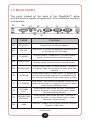
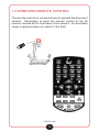
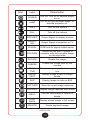
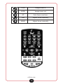
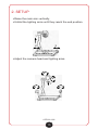
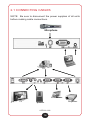
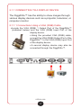
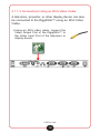
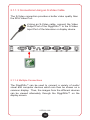
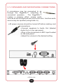
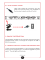
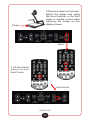
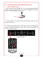
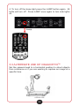
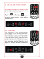
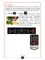
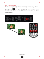
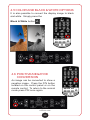
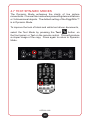
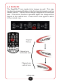
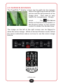
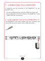
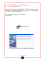
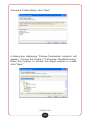
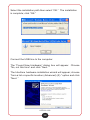
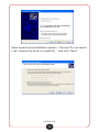
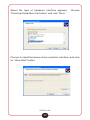
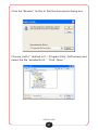
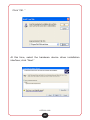
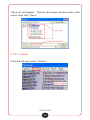
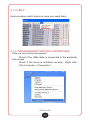
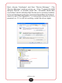
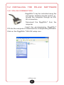
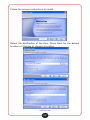
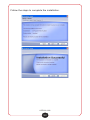
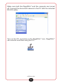
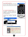
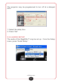
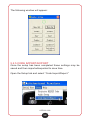
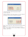
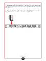
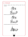
DiggiDitto™ DC896 Document Camera User Manual DiggiDitto™ DC896 Document Camera Thank you for purchasing the Califone® DiggiDitto™ DC896 Document Camera. We encourage you to visit our website, www.califone.com, to register your product for its warranty coverage. While you’re there, you can sign up to receive our newsletter, download our catalog, and learn more about the complete line of Califone® audio visual products. Our product line includes portable and installed wireless PA systems, multimedia players and recorders, headphones and headsets, computer peripheral equipment, visual presentation products, and language learning materials. The DiggiDitto™ DC896 Document Camera provides both an interactive learning experience and the capability of acting as a multimedia switcher. Its incredible 12x Optical Zoom allows for viewing amazing detail with a crisp and clear picture. The classroom uses of the DiggiDitto™ DC896 Document Camera will bring a new enthusiasm and long-lasting retention into your learning experience! Please take the time to read through this instructional manual. The information included will aid you in the optimal operation of your document camera. califone.com 2 KEY FEATURES 1,300,000 pixel resolution Base Light 8 ½”x 11” Save infinite pictures via USB Control Functions Positive/Negative 3 Light Modes Brightness Control Sharpness Control White Balance Input Source Standby /Resume Zoom +/Focus +/- 12x Optical Zoom Annotation Feature Remote Control Auto Focus Freeze Image Text and Dynamic Modes Volume Control Capture Image Mirror Image Split Screen Color to Black & White califone.com 3 IMPORTANT SAFETY INSTRUCTIONS ATTENTION: All safety and operating instructions should be read before operating appliance. All operating and use instruction should be followed when operating the appliance. Heed and adhere to all warnings on the appliance and in the operating instructions. Retain all savety and operating instructions for future reference. CLEANING—The appliance should be cleaned only as recommended by the manufacturer. Always unplug before cleaning the device. Use a damp, soft cloth for cleaning Do not use volatile solvent. WATER & MOISTURE—Do not sue the appliance near water. i.e. bathtub, kitchen sink, laundry tub, wet basement, or swimming pool. OBJECT & LIQUID ENTRY—Care should be taken so that objects do not fall and liquids are not spilled into the enclosure through openings. VENTILATION—Do not situate the appliance so that its location or position interferes with its proper ventilation. For example, the appliance should not be situated on a bed, sofa, rug, or simialr surface that may block the ventilation openings. The appliance should not be placed in a built-in intallation—such as a bookcase or cabinet—that may impede the flow of air through the ventilation openings. DAMAGE REQUIRING SERVICE—The appliance should be serviced by qualified service personnel when: (A) the power supply cord or the plug have been damaged, (B) objects have fallen or liquids have been spilled into the appliance, (C) the appliance has been exposed to rain, (D) the appliance does not appear to be operating normally or exhibits a marked change in performance, or (E) the appliance has been dropped or the enclosure has been damaged. HEAT—Situat the appliance away from heat sources such as radiators, heat registers, stoves, or other appliances (including amplifiers) that produce heat. SERVICING—The user should not attempt to service the appliance beyond the steps described in the operating instructions. For all other servicing refer to qualified service personnel. NON-USE PERIODS—Unplug the appliance pouwer cord from the outlet when left unused for a long period of time. POWER SOURCES—Connect the appliance only to a power supply type described in the operating instructions or marked on the appliance. LOCATION—Place the device on a stable surface to prevent injuries or damage. Do no place in direct sunlight. Keep camera away from acid or alkali gasses. Do not place in humid, dusty, or windy locations. Keep within the recommended environment: Temperature of 0ºC–45ºC (32ºF–113ºF) and humidity less than 75 %. POLARIZATION or GROUNDING— Precautions should be taken so that the grounding or polarization means of the appliance are not defeated. ABNORMAL FUNCTIONALITY—If this equipment functions abnormally, shuch as putting off smoke, smells, or noise, immediately unplug and call for professional assistance. POWER CORD PROTECTION—Power supply cords should be routed so that they are not likely to be walked on or pinched by items placed upon or against them. Pay particular attention to cords at plugs, conveninece receptacles, and the point where they exit from the appliance. califone.com 4 DiggiDitto™ DC896 Document Camera TABLE OF CONTENTS 1. PART NAMES AND FUNCTIONS 8 1.1 Control Panel 1.2 Back Panel 1.3 Side Panel 1.4 Wireless Remote Control 9 10 11 12 2. SETUP 15 2.1 Connecting Cables 16 2.2 The Power Cord 21 2.1.1 Connecting to a Display Device 17 2.1.1.1 Connections Using a VGA (RGB) Cable 17 2.1.1.2 Connections Using an RCA Video Cable 18 2.1.1.3 Connections Using an S-Video Cable 19 2.1.1.4 Multiple Connections 19 2.1.2 Speakers and Microphone Connections 20 3. BASIC OPERATION 21 3.1 Simple Instructions for Presenting 3.2 Presenting Transparencies or Slide Film 3.3 Alternate use of DiggiDitto™ 21 23 24 4. DETAILED FUNCTIONS 25 4.1 Display Input Selection 4.2 Lighting 4.3 Zoom 4.4 Focusing 4.5 Color and Black & White Options 4.6 Positive/Negative Conversion 4.7 Text/Dynamic Modes 4.8 Rotate 4.9 Screen Division 25 25 27 28 29 29 30 30 32 califone.com 5 5. CONNECTING TO A COMPUTER 33 5.1 USB Connection with EzPreview 1.0 5.1.1 EzPreview 1.0 Installation 5.1.1.1 Setup Applications 5.1.1.2 Driver Installation 5.1.2 Using EzPreview Controls 5.1.2.1 Saving an Image 5.1.2.2 Control 5.1.2.3 Recording Video 5.1.2.4 Annotation 5.1.3 Help 5.1.4 Troubleshooting with EzPreview 5.2 Installing the RS-232 Software 5.2.1 RS-232 Connection 5.2.2 Serial Ports 5.2.3 Projector Setup 5.2.4 Audio Setup 5.2.5 Code Import/Export 33 34 34 36 43 44 45 46 48 49 49 51 51 55 55 57 58 6. STORAGE 7. TROUBLESHOOTING 8. TABLES AND CHARTS 61 62 63 8.1 Functions and their Control Devices 8.2 Specifications 63 64 califone.com 6 PACKAGE CONTENTS The DiggiDitto™ DC896 Document Camera kit contains the following: 96 DC8 o™ mera iDitt a Digg ment C u Doc DiggiDitto™ DC896 Document Camera USB Cable l nua r Ma Use User Manual VGA Cable Software CD califone.com 7 Remote Control Power Adapter and Cord 1. PART NAMES AND FUNCTIONS 1. Infrared Receiver 3. Upper Arm 2. Camera Head 4. Camera Lens 5. Main Arm 6. Upper Light 8. Base Light 7. Lamp Arm 9. Remote Control Slot 10. Side Panel 11. Control Panel califone.com 8 1.1 CONTROL PANEL 13. 14. 21. 15. 22. 16. 12. 23. 17. 18. 19. 20. 24. Icon Function 12. Power On/Off 13. Freeze 14. Light Control 15. Text and Picture Modes 16. Output Display to PC Monitor 17. Output Display to Projector 18. Brightness Control 19. Auto Focus 20. Zoom In/Out 21. Positive and Negative Modes 22. Color and Black/White Modes 23. Screen Division 24. Rotate Image califone.com 9 1.2 BACK PANEL The ports located at the back of the DiggiDitto™ allow connections to a variety of equipment—from computer monitors to projectors. 25. 26. 27. 31. 29. 28. 32. 33. 34. 30. Label Function 25. DC-IN-12V Power Socket for the AC adaptor. 26. RS 232 Serial Port. To control the document camera from a PC through the RS-232 cable. 27. S-VIDEO S-Video Output. Connects to TV or other display device; shows document camera images. 28. VIDEO OUT RCA Video Signal Output. Connects to TV or other display device; show document camera images. 29. AUDIO OUT Stereo Audio Output, PC Audio Output. Connects to speakers. May use converter for other audio connections. 30. AUDIO IN Stereo Audio Input. PC Audio Input. To transfer audio through document camera to connected speakers. May use converter to input other types of audio. 31. PC RGB IN RGB Inputs. May connect computers or other AV, to show that information through the document camera onto connected display screen. 32. PC RGB OUT RGB Outputs (also known as VGA). Connects to monitor, projector, or other display device; shows document camera images. 33. PROJECTOR RGB OUT RGB Outputs (also known as VGA). Connects to monitor, projector, or other display device; shows document camera images. 34. USB USB port. Images may be saved onto the computer through a USB cable. califone.com 10 1.3 SIDE PANEL 35. 36. 37. 38. Label Function 35. VOL Microphone Volume Control 36. MIC Microphone input. May use converter to input other types of audio. 37. RGB IN RGB Input (VGA). May connect computers or other AV to show information through the document camera onto connected display screen. 38. AUDIO IN PC Audio Input. To transfer audio through document camera to connected speakers. May use converter to input other types of audio. califone.com 11 1.4 WIRELESS REMOTE CONTROL The remote control is a convenient way to operate the document camera. Remember to point the remote control at the IR receiver located at the front base of the camera. Its receivable range is approximately six meters (19.6 feet). califone.com 12 Icon Label Description POWER Turn on/ Turn off or decode projector on. LAMP On/ off of the visualiser lamps, or decode projector off. VOL+ Turn on the volume VOL- Turn off the volume PREVIEW Output Signal to display screen SHOOTING Output Signal to projector or TV SIGNAL RGB and AV signal output switch DIVISION Freeze the left part of image to compare with the movable image on the right side ROTATE Rotate the image FREEZE Freeze the image shot by the camera NEGATIVE Display image in positive or negative IMAGE/ TEXT Display image in text or image mode B/W Display image in color or B/W CAPTURE Store the exact image captured PREVIEW Display image captured and stored NEXT Choose next image to review or delete PLAYBACK Display stored image in full screen DELETE Delete captured image califone.com 13 TELE Image zoom in WIDE Image zoom out AF Auto focus one time FAR Adjust focus manually NEAR Adjust focus manually califone.com 14 2. SETUP Raise the main arm vertically. Unfold the lighting arms until they reach the end position. 1 2 3 Adjust the camera head and lighting arms. 5 4 6 7 califone.com 15 6 2.1 CONNECTING CABLES NOTE: Be sure to disconnect the power supplies of all units before making cable connections. Microphone one PC LCD Screen TV Speaker califone.com 16 Projector 2.1.1 CONNECTING TO A DISPLAY DEVICE The DiggiDitto™ has the ability to show images through various display devices such as a projector, television, or computer monitor. 2.1.1.1 Connections Using a VGA (RGB) Cable Locate the VGA (RGB) 1 Output Port of the DiggiDitto™ (indicated below) and the VGA (RGB) Input Port of the display device. Using the provided VGA (RGB) cable, connect the VGA (RGB) Output Port of the DiggiDitto™ to the VGA (RGB) Input Port of the display device. A second display device may also be connected through the DiggiDitto™. califone.com 17 2.1.1.2 Connections Using an RCA Video Cable A television, projector, or other display device can also be connected to the DiggiDitto™ using an RCA Video Cable. Using an RCA video cable, connect the Video Output Port of the DiggiDitto™ to the Video Input Port of the television or display device. califone.com 18 2.1.1.3 Connections Using an S-Video Cable The S-Video connection provides a better video quality than the RCA Video Port. Using an S-Video cable, connect the Video Output Port of the DiggiDitto™ to the S-Video Input Port of the television or display device. 2.1.1.4 Multiple Connections The DiggiDitto™ can be used to connect a variety of audio/ visual and computer devices which can then be shown on a common display. Thus, the images from the different devices can be viewed alternately through the DiggiDitto™ on the display screen. califone.com 19 2.1.2 SPEAKERS AND MICROPHONE CONNECTIONS A microphone may be connected to go through the DiggiDitto™ outputting to connected speakers. The DiggiDitto™ creates a karaoke effect, mixing audio sources as the microphone acts as a voice-over. Another audio source may be inputted (using Audio In). All power sources should be turned off before making cord connections. Connect speakers to Audio Out (labeled Audio Out o n the rear panel). Plug in the microphone to MIC input located on the side panel. Adjust the volume to the desired setting. califone.com 20 2.2 THE POWER CORD Lastly, after making all connections, plug the power cord into the power cord receptacle of the document camera and the AC outlet. 3. BASIC OPERATION The DiggiDitto™ DC896 may be controlled using the front panel, wireless remote control, or through the computer via USB or RS-232 connection. 3.1 SIMPLE INSTRUCTIONS FOR PRESENTING 1. After connecting the DiggiDitto™ to an accompanying display device (monitor, projector, etc.), turn ON the DiggiDitto™ power switch. The side lights will illuminate. califone.com 21 Power 2.Place the object on the base. Adjust the image size using the zoom buttons on the front panel or remote control while watching the image on the display screen. Zoom 3. On the control panel,press Auto Focus. Auto Focus califone.com 22 3.2 PRESENTING TRANSPARENCIES OR SLIDE FILM 1. After connecting the DiggiDitto™ to an accompanying display device (monitor, projector, etc.), turn ON the DiggiDitto™ power switch. The side lamps will light up. Power 2. Press LAMP. The base light will illuminate and the side lamps will turn off. 3. If showing a negative film, press the P/N (Positive/Negative) button to change to Negative view. When ready, press again to return to Positive view. Positive/Negative califone.com 23 4. To turn off the base light press the LAMP button again. All lights will turn off. Press LAMP once again to turn side lights on. Lamp 3.3 ALTERNATE USE OF DIGGIDITTOTM Set the camera head to a horizontal position to shoot objects from a distance or if you are wanting to capture an image at a specific time. califone.com 24 4. DETAILED FUNCTIONS 4.1 DISPLAY INPUT SELECTION To select the audio/visual input device to be shown on the display, press the Monitor or Projector button located on the front control panel or on the remote control. Press again to alternate input. 4.2 LIGHTING The DiggiDitto™ uses environmentally friendly LEDs for the side and base lights. These LED bulbs require much less energy than standard incandescent light bulbs. LEDs can last for many years and rarely need to be replaced. LED lights also have the benefits of being rugged, generating very little heat, and not flickering! All of which are valuable features for classroom use. califone.com 25 The DiggiDitto™ has three light settings: Upper Light On, Base Light On, and All Lights Off. The Upper Light ON option illuminates printed materials and 3-dimensional objects, whereas the Base Light ON setting presents transparencies such as slides or negatives. If the natural environment light is sufficient, it may be desirable to use DiggiDitto™ with all lights turned off. When the document camera is initially powered, the upper lights turn on by default. To change the setting press the Lamp button located on the front control panel or on the remote control. The light setting will change within a second or so. Please note that both the upper light and base light cannot be on simultaneously. Upper Lights On Base Light On califone.com 26 All Lights Off 4.3 ZOOM The DiggiDitto™ has the ability to zoom in on an object up to ninety-six times its original size! This powerful zoom feature multiplies a 12x optical magnification together with a 9x digital enlargement, allowing for incredibly detailed viewing. Press the ZOOM+ or ZOOM– button on the front control panel or remote control to adjust the view. Pressing ZOOM continuously speeds up the function. After zooming, the DiggiDitto™ Auto Focus is activated although it may be necessary to manually adjust the focus and brightness. califone.com 27 4.4 FOCUSING The focus may be adjusted automatically or manually. Press Auto Focus on the DiggiDitto™ front control panel for automatic focus or use the remote to control the focus incrementally. califone.com 28 4.5 COLOR AND BLACK & WHITE OPTIONS It is also possible to convert the display image to black and white. Simply press the Black & White button . 4.6 POSITIVE/NEGATIVE CONVERSION An image can be converted to show a negative image. Press the P/N button located on the control panel or on the remote control. To return to the normal mode press P/N once again. califone.com 29 4.7 TEXT/DYNAMIC MODES The Dynamic Mode enhances the clarity of live picture movements. Choose this mode when presenting demonstrations or 3-dimensional objects. The default setting of the DiggiDitto™ is in Dynamic Mode. To improve the look of black and white text driven documents, select the Text Mode by pressing the Text button on the front panel, or Text on the remote control. This will produce a crisper image of the copy. Press again to return to Dynamic Mode. califone.com 30 4.8 ROTATE The DiggiDitto™ can create mirror images as well. This may be done by pressing Rotate on the front control panel or on the remote control. The first mirror image is flipped on a horizontal axis. If the mirror function is pressed again the image will be flipped its the vertical axis. Press mirror once again to return to the normal view. Original Picture Flipped on a horizontal axis. Flipped on a vertical axis. califone.com 31 4.9 SCREEN DIVISION The DiggiDitto™ display screen can be split into two images where the right side shows a frozen picture and the left presents a live image shot. This view is very helpful for comparisons. Simply press the Division button on the front control panel, or the Division button on the remote control to obtain the divided view. The image on the left of the split screen can be flipped to show the mirror image. While in Screen Division mode, follow the same instructions above on how to use the mirror image feature. califone.com 32 5. CONNECTING TO A COMPUTER A computer may be connected to the DiggiDitto™ for two separate uses: To save endless pictures using the USB connection and As a method to control the functions of the DiggiDitto™ using USB or RS-232 connections. 5.1 USB CONNECTION WITH EZPREVIEW 1.0 The DiggiDitto™ may save images onto your computer and control the document camera via an USB connection. califone.com 33 5.1.1 EZPREVIEW 1.0 INSTALLATION 5.1.1.1 Set up applications Insert the accompanying DiggiDitto™ CD into the computer to upload the corresponding software. Double click “EzPreview. exe” from the software bundle. The installation image will be shown; click “Next.” EzPreview.exe califone.com 34 Choose a Folder Name; click “Next.” A dialog box displaying “Choose Destination Location” will appear. Choose the location “C:\Program Files\EzPreview.” Enter this location or choose the target location to install; click “Next.” califone.com 35 The “Installation Complete” window will appear; click “Finish.” 5.1.1.2 Driver Installation Double click “EzPreview driver.exe” EzPreview driver.exe The Installation window will appear; click “Next.” califone.com 36 The Installation complete window will appear; click “Finish” to end the driver installation. Click "Yes" to install the VCM interface. Choose "Yes" to agree to the license agreement. califone.com 37 Select the installation path then select “OK.” The installation is complete; click “OK.” Connect the USB line to the computer. The “Found New Hardware” dialog box will appear. Choose “No, not this time” and click “Next. ” The Interface hardware installation wizard will appear; choose “from a list or specific location (Advanced) (S) ” option and click “Next. ” califone.com 38 Select search and installation options. Choose “Do not search. I will choose the driver to install (D), ” and click “Next.” califone.com 39 Select the type of hardware interface appears. “Universal Serial Bus Controllers” and click “Next. ” Choose Choose to install the device driver selection interface, and click on “Have Disk” button. califone.com 40 Click the “Browse” button to find the documents dialog box Choose “path 1” (default is C: \ Program Files \ EzPreview) and select the file “ezusbw2k.inf. ” Click “Open. ” califone.com 41 Click “OK. ” At this time, select the hardware device driver installation interface; click “Next.” califone.com 42 A Safety tips screen will appear; click “Continue Anyway.” The installation is complete interface click “complete" to end. 5.1.2 USING EZPREVIEW CONTROLS Connect the document camera to the computer with the provided USB cable. The flat (Type A) connector fits to the computer; the squared (Type B) connector attaches to the DiggiDitto™. Power on the document camera. Open EzPreview by clicking on the shortcut located on the desktop. califone.com 43 5.1.2.1 Saving an Image To save an image, select “Capture.” califone.com 44 “Save as” will appear. Choose the image location enter a file name, then click “Save.” 5.1.2.2 Control Click the left top corner “Control.” califone.com 45 It is now possible to control the DiggiDitto™ with the corresponding operations. 5.1.2.3 Recording Video Click on “Record” then “Start Record.” Press “Finish Record” when done. It is then possible to save the recording. califone.com 46 When the video is complete or you want to stop the recording, click on the end of the video A drop-down menu appears in the compressed format selection dialog box. Select a compression format as shown in picture (e.g. “Microsoft Windows Media Video 9”). If you do not need compression, select “full-frame (non-compressed),” another option in the menu; click OK” to start the video. ” califone.com 47 5.1.2.4 Annotation To draw on the picture, press “Paint.” Select the kind of brush, width, and color. califone.com 48 5.1.3 HELP Help provides useful topics in case you need them. 5.1.4 TROUBLESHOOTING WITH EZPREVIEW Device can not be recognized Check if the USB cable is connected to the backside. No image Check if the driver is installed correctly. Right click “My Computer -> Properties.” califone.com 49 Next, choose “Hardware” and then “Device Manager.” The “Device Manager” window comes up. If the “Cypress Ez-USB Sample Device” is located under the “Universal Serial Bus Controllers” which indicates that the device is correctly installed. If it is not displayed under the “Universal Serial Bus Controllers”, check to see if the DiggiDitto™ is connected correctly or if it is powered on. If it is still not working, install the driver again. califone.com 50 5.2 INSTALLING THE RS-232 SOFTWARE 5.2.1 RS-232 CONNECTION DiggiDitto™ may be controlled using the front panel, wireless remote control, or through the computer through an RS232 connection. Disconnect the DiggiDitto™ from the computer. Insert the accompanying DiggiDitto™ CD into the computer to download the corresponding software. Click on the DiggiDitto™ RS-232 setup icon. califone.com 51 Follow the screen instructions to install. Select the destination of the files. Press Next for the default location or Change to choose a location. califone.com 52 Follow the steps to complete the installation. califone.com 53 Make sure both the DiggiDitto™ and the computer are turned off. Connect the document camera to the PC with the included RS-232 cable. Turn on the PC, and click on the DiggiDitto™ icon. DiggiDitto™ can now be controlled using the PC. califone.com 54 5.2.2 SERIAL PORTS If there are multiple units connected to the PC, select “Serial Port” to choose the port to control the document camera. 5.2.3 PROJECTOR SETUP To control a projector through the DiggiDitto™ using the RS-232, the projector needs to be programmed by the following steps. To program the projector code, select “Setup” then “Projector RS-232C Code.” The following box will appear: califone.com 55 1. Select whether it is a name brand projector or if a custom code is needed 2. Choose the projector brand 3. Choose the projector model 4. Set the function 5. Enter the code 6. Press “Write” If this software did not list the brand of projector or if there is no reference type, set up the following: 1. Select the custom code 2. Select the code form 3. Choose the baud rate 4. Set the function 5. Enter the code 6. Press “Write” califone.com 56 The projector may be programmed to turn off at a delayed time. 1. Select the delay time 2. Press “Set” 5.2.4 AUDIO SETUP The audio of the DiggiDitto™ may be set up. From the Setup menu, press “Audio Setup.” califone.com 57 The following window will appear: 5.2.5 CODE IMPORT/EXPORT Once the setup has been completed these settings may be saved and then imported/exported to save time. Open the Setup tab and select “Code Import/Export.” califone.com 58 1. Press “Download"; wait for the process to finish. 2. Press “Save File.” If there is mistake in the setup process or if many modes of visualization must be set up, operate the following: Step 1: Press “Open File;” open the file which has been saved as .bin. Step 2: Press “Upload” and wait for the process to finish. Step 3: If you want to set up many different visualization displays, repeat Step 2. califone.com 59 1. Make sure both the DiggiDitto™ and the computer are turned off. Connect the document camera to the PC with the included RS-232 cable. 2. Turn on the PC and click on the DiggiDitto™ icon. Your DiggiDitto™ can now be controlled using the PC. califone.com 60 6. STORAGE Fold the lighting arms down until they reach the end position. 3 4 1 2 Rotate the camera head back. 3 4 1 2 Fold the head and connecting arm down. 5 6 califone.com 61 7. TROUBLESHOOTING How is the remote control battery replaced? The DiggiDitto™ remote control uses a CR2025 battery which can be purchased at most electronics stores. To change the battery: 1. Turn over the remote control so that the back side faces up. 2. Push in the notch located on the side of the battery holder and pull. 3. Replace with a new CR2025 battery. Why is there no image? Make sure the cables and power cord are properly connected. Check to make sure the power switch is turned on. It’s also possible that the fuse needs to be replaced. The image is bending; how is a straight image obtained? Adjust the camera position. Why is the image out of focus? The object may be too close to the lens. The Focus may be at the maximum Zoom setting. Press Zoom —. Try pressing Auto Focus. If you are in a damp climate, moisture may accumulate on the lens. It will disappear gradually as the equipment warms up. Why is the image so dark? Lighting may be insufficient. Press LAMP to activate the side lights then increase the brightness level. califone.com 62 8. TABLES AND CHARTS 8.1 FUNCTIONS AND THEIR CONTROL DEVICES Function Front Control Panel Remote RS-232 Control USB Power Power Power Light Control Lamp Lamp Lamp Zoom In/ Out Tele/Wide Zoom +/- Tele/ Wide Brightness Control Brightness +/- Freeze Freeze Freeze Rotate Rotate Rotate Text/ Picture Modes Text Text Positive/ Negative Modes Negative Negative Negative Color and Black/ White Modes B.W. B.W. B.W. Volume Control Vol +/- Vol +/- Vol +/- Auto Focus AF AF Manual Focus Near/Far Near/Far Signal Signal Signal califone.com 63 Ouput Display Selection Monitor, Projector Fun 1, 2, 3 x x Not appl: Preview, Capture, Playback, Next, Delete x x DVD: play, pause, next, previous, ff, rew x x DVD cont: Menu, esc, enter, stop Monitor, Projector x 8.2 SPECIFICATIONS Compatible Operating Systems Windows 98/2000/NT/ME/XP, Vista 32-bit, Windows 7 32-bit califone.com 64 Optics Video System Multimedia Function Illumination Input Camera F1.6~3.7, f3.9~85.8mm Shooting Area 357*280 Zoom Optics zoom>=12 ,Digital zoom>=8 Focus Auto /Manual Aperture Auto Image Apparatus 1/3" Image Sensor Total Pixels 1,300,000 Horizontal clarity >=750TV line SNR >=50dB White Balance Auto/Manual Comparison >=2 separate screen Function W/B, negative/positive, mirror image, text, Brightness modulation, freeze, preview/ shooting, electric volume control. Direct Connection Without Boot-strap Signal When PC signal enter into visual presenter, would continually enter the display, and no need start the system. Assistant lamp LED Baselight LED AV part Microphone input*1 califone.com 65 RGB*2 (3 routes matrix switch) VGA part Audio frequency (stereo)*2 Output RS-232 Computer control*1 AV part Video*1 S-Video * 1 VGA part RGB*2 (Matrix output) Audio frequency(stereo)*1 Output Format Control Modes Camera Rotation Angle Size (W*D*H) RS-232 Control of the projector or other*1 equipment* 1 CON Infrared emission* 2 Power supply DC 12V 1.5A PAL 2:1 line-to-line scan VGA line-toline scan 1280*1024 Control panel, remote controller, RS-232 control software 350 angle horizontally, 350 angle vertically Set up 470*435*520mm Folded 490*493*140mm 5 KGS Weight Power Power DC 12V 3A Energy Consumption <= 15W califone.com 66 DiggiDitto™ DC896 Document Camera Warranty Califone® warrants the DC896 to be free from defective material and workmanship for two years from the purchase date. Our “Project Intercept” Customer Satisfaction program will replace defective parts and repair malfunctioning equipment under this warranty if the defect occurs under normal use. All Damage Claims Must Be Made With the Freight Carrier Notify the freight carrier immediately if you observe any damage to the shipping carton or product. Repack the unit in the carton and await inspection by the carrier’s claim agent. Notify your dealer of the pending freight claim. Returning Your Unit for Service or Repairs Should your unit require service, contact our Customer Service Department online at califone.com/techsupport, via email at [email protected], or by phone at 800-722-0500 / 818407-2400 (international customers) to first obtain an RA (Return Authorization) number before returning it to Califone®. The unit must be returned to our factory via prepaid transportation only after the factory issues an RA number which must be clearly written on the outside of the box. califone.com 67 Califone® International, Inc. 1145 Arroyo Avenue, #A San Fernando, CA 91340 USA Toll Free 800.722.0500 | Toll Free Fax 877.402.2248 International Customers call 818.407.2400 or Fax 818.407.2405 califone.com Califone DC896 Rev 01 1009