1
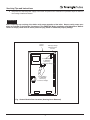
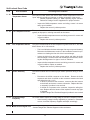
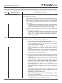
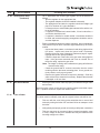
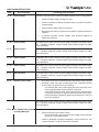
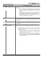
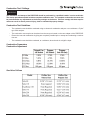
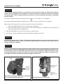
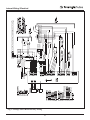
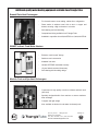
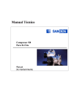
prestige
Condensing
Water Boiler
SERVICE TECHNICIAN’S
TROUBLE SHOOTING GUIDE
Date revised: 5/11/09
2008-36 TSG-PRESTIGE
Table of Contents
INTRODUCTION
Page 1-2
SERVICING TIPS AND INSTRUCTIONS
Page 3-4
CONTROL MODULE DISPLAY - GENERAL
Page 5-9
PRESTIGE CONTROL MODULE DISPLAY
Page 10-11
SOFT LOCKOUT ERROR CODE
Page 12-16
HARD LOCKOUT ERROR CODE
Page 17-24
COMBUSTION TEST / SETTINGS
Page 25-26
INTERNAL WIRING / ELECTRICAL
Page 27-29
REPLACEMENT PARTS
Page 30-40
TORQUE SPECIFICATIONS
Page 41
i
Introduction
Definitions
WARNING
Indicates a potentially hazardous situation which, if ignored, can result in death, serious injury or substantial property damage.
CAUTION
Indicates a potentially hazardous situation which, if ignored, can result in minor injury, property damage.
NOTICE
Indicates special instructions on installation, operation or maintenance, which are important to the equipment/product, but not related to personal injury hazards.
WARNING
This guide is to be used in conjunction with the PRESTIGE Boiler Installation and Maintenance Manual.
Procedures and servicing listed in this manual must be performed by a qualified service technician,
installer, service agency or gas supplier. Any procedures or service performed by an unqualified individual or service agency can result in severe personal injury, death or substantial property damage.
1
Introduction
Introduction
This guide is to be used in conjunction with the Triangle Tube PRESTIGE Boiler Installation and Maintenance Manual.
Good Troubleshooting Practices
Before leaving for the job site:
Check your parts and tools
•
•
Test equipment and tools you will need:
Electrical meter that tests both voltage (AC/DC), continuity (ØW), resistance (
Temperature gauge or metering device
Manometer
Calibrated Combustion Analyzer
Standard tools of the trade (wrenches, screwdrivers...)
W,ohms), and frequency (Hz)
Parts to solve most problems
Control module
Transformer with surge protection
Blower with gasket
PS 399 Parts Case - PSRKIT102
PS 60-250 Parts Case - PSRKIT103
Review all appropriate manuals before leaving for the job site
At the job site:
-
Clarify problem
-
Have the PRESTIGE manual and any other wiring, zone control or piping diagrams, or installation guides readily
available.
REMEMBER
Follow the Troubleshooting Guide step by step, always double checking your results. Skipping steps or not completing steps can lead to wrong conclusions, repeated visits to the job site, unhappy customers and unnecessary warranty claims.
2
Servicing Tips and Instructions
WARNING
Label all wires and wire connections prior to disconnecting when servicing any boiler controls. Wiring errors
can cause improper and dangerous operation. Always disconnect the power supply to the boiler before servicing. Failure to comply could result in severe personal injury, death or substantial property damage.
WARNING
Never bypass (jumper) any boiler, control or device except for momentary testing when troubleshooting the
boiler as outlined in this guide, severe personal injury, death or substantial property damage can result.
Initial Troubleshooting Checks
-
Ensure all wire connectors to the control module and sensors are securely connected.
-
Ensure the maximum gas supply pressure does not exceed 13”w.c. during flow or no flow conditions.
-
Ensure the gas supply pressure is a minimum 5” w.c. during flow conditions (burner firing on all gas appliances).
Control Module Fuses
NOTICE
The control module contains 2 internal replaceable fuses. Ensure the fuses are in working condition prior to
replacing the control module or any boiler component. If one of the fuses has blown, it will prevent the control module and/or boiler components from operating properly.
To check or replace the control module fuses:
1. Disconnect the external power supply to the boiler.
2. Remove the front jacket panel of the boiler by removing the thumb screw along the top edge.
3. Remove the electrical connectors at the MCBA control module for the igniter, transformer and display (ribbon
cable) and the black plastic housing cover off the control module. Use care not to damage the cover when
removing it.
4. Remove both fuses and check for continuity to determine if fuse is blown, replace if necessary.
5. The control module is supplied from the factory with 2 spare fuses, a 5 amp fast acting fuse and a 4 amp slow
acting fuse, attached to the control module cover.
6. When replacing the fuses ensure the amp rating and type of the fuse matches the replacement fuse. Reference
Fig. 1, page 4 for amperage and location of the fuses.
WARNING
Do not bypass any fuse with a jumper. Do not replace any fuse with a fuse that is not specified. Failure to
comply could result in severe personal injury, death or substantial property damage.
7. Re-install the control module cover, electrical connectors and the front jacket panel when completed.
3
Servicing Tips and Instructions
8. Reconnect the external power supply to the boiler and perform the verification of operation steps as outline in
the Prestige Installation Manual.
WARNING
After completing any servicing of the boiler verify proper operation of the boiler. Steps to verify proper operation are outlined in the Start-Up Procedures in the PRESTIGE Boiler Installation and Maintenance Manual.
Failure to comply could result in severe personal injury, death or substantial property damage.
Control
Module
120V-High Voltage
Electrical Quick
Connect
F1 Fuse Rating
5 - AMP/250V
Fast Acting
for 120V-High Voltage
F3 Fuse Rating
4 - AMP/250V
Slow Acting
for 24V-Low Voltage
Fig. 1 Control Module Fuse Locations (Housing Cover Removed)
4
Control Module Display - General
Standby Mode
TO TEMPORARILY PLACE THE BURNER
INTO LOW FIRE TEST MODE: press the MODE
button until “StbY” is displayed. Then press and
hold both MODE and “-” buttons simultaneously
until the first digit flashes “L”.
StbY
After the boiler is turned on, the control panel will be in the
STANDBY mode.
This is the standard mode for the PRESTIGE. The control
automatically returns to this mode after 20 minutes if no
keys have been pressed on the display. Any parameters
that were modified are then stored.
TO DEACTIVATE THE HIGH OR LOW FIRE
TEST MODE: press the MODE button until
“StbY” is displayed. Then press and hold both the
“+” and “-” buttons simultaneously to deactivate the
high or low fire test mode.
The first character shows (on the left side of the display)
the current status of the boiler depending on the condition
of both the boiler and the burner. The last 3 characters
indicate the boiler supply temperature.
NOTICE
If the burner is blocked due to a “soft” lockout, the display
alternates between a 9 followed by the boiler supply temperature and “b” with a two digit error code. See page 12
-16 for detailed information on the corrective and preventive actions for the soft lockouts.
Display
A180
H 180
L 180
If the “+” button is held in, the CH system
(parameter 3) will be turned OFF and the display will show “cOFF”. Press and hold the “+”
button to turn the CH system back ON, the display will show “c” followed by CH set point. If
the “-” button is held in while in the “StbY”
mode, domestic system (parameter 2) will be
turned OFF and the display will show “dOFF”.
Press and hold “-” button to turn the domestic
system back ON, the display will show “d” followed by domestic set point temperature.
Boiler function
Internal check
Test function: Burner on, high fire mode
Test function: Burner on, low fire mode
TO TEMPORARILY PLACE THE BURNER
INTO HIGH FIRE TEST MODE: press the MODE
button until “StbY” is displayed. Then press and
hold both the MODE and “+” buttons simultaneously until the first digit flashes “H”.
While in the test mode:
-
high limit will function
-
boiler CH circulator will function
-
domestic circulator will not function
-
the test mode will time out in approximately
10 minutes
5
Control Module Display - General
Standby Mode Display
Display
0 180
1 180
2 180
3 180
4 180
5 180
6 180
7 180
8 180
9 180
b 18
Boiler function
STANDBY, no demand
Fan prepurge or post purge cycle
Ignition sequence
Burner ON for space heating (CH)
Burner ON for domestic hot water (DHW)
Pre-check for air flow prior to prepurge cycle
Burner OFF due to reaching temperature setpoint
Space Heating (CH) post pump cycle
Domestic hot water (DHW) post pump cycle
Burner blocked:
Supply temperature too high (202 F) . Burner
will remain OFF until temperature drops
below 200 F
b 19
Return temperature too high (202 F). Burner
will remain OFF until temperature drops
below 200 F
b 24
Return temperature is higher than
supply temperature. Burner will remain OFF
until corrected.
b 25
Supply temperature increased too quickly.
Burner will remain OFF for a 10 minute period.
Burner will recycle, increasing waiting period 1
minute for a max. 15 minutes
b 26
Factory supplied LWCO device or
external limit (terminals 15 & 16) is OPEN.
Burner off for 150 seconds, auto reset.
b 28
b 29
b 30
b 33
b 35
b 38
b 40
b 52
b 65
b 11 6
b1 18
No blower signal
Blower signal present with no demand, Burner
will remain OFF until condition terminates
Temperature difference between the supply and
return is more than 72 F. Burner will remain OFF
for 150 seconds. Burner will recycle increasing
wating period 1 minute for a max. 20 cycle.
Indirect water heater temperature sensor is
short-circuited. Burner OFF until corrected.
Flue temperature sensor is short-circuited.
Burner OFF until corrected
Indirect water heater temperature sensor is
“open” or disconnected. Burner OFF until
corrected.
Flue temperature senor is “open” Burner OFF
until corrected.
Flue temperature greater than 240 F but less
than 250 F. Burner off for 150 seconds
Wait for the blower to start
Power frequency deviation
Flame current signal lost
6
Control Module Display - General
Key:
Parameter Mode
P ARA
STEP
STEP
To access PARAMETER mode when the system is in
STANDBY mode, press the MODE button once.
STEP
STEP
Key:
Display
MODE
P ARA
Display
Description of parameters
1.
. 140
2. 01
3. 01
4.1 8 6
Domestic Hot Water Setting (See Note 1)
DHW Application Selection (See Note 2)
CH Application Selection (See Note 3)
CH Maximum Boiler Operating Setpoint
Note 1: This parameter is factory set to 140ºF. It is important to note the control adds 46ºF to this setting, therefore
the actual domestic hot water boiler setpoint is 140ºF +
46ºF = 186ºF.
Pressing MODE once
To scroll through the list of parameters, simply press the
“STEP” button. The First digit is the parameter number followed by the parameter value. To modify a parameter
value, use the + or - keys. Then press “STORE” to save
the value you just changed. The display flashes once to
confirm the data has been saved.
Note 2: This parameter should not be changed from the
factory setting of 01. The performance of the DHW
(Domestic Hot Water Heating) will be affected and can
become unreliable.
Note 3: This parameter should not be changed from the
factory setting of 01. The performance of the CH
(Central/Space Heating) will be affected and can become
unreliable.
To activate the parameters you changed, press RESET.
However, if you do not press a key, the system returns to
STANDBY mode after 20 minutes and automatically
stores the changes.
7
Control Module Display - General
Accessing Boiler Information
NOTICE
Information mode
Key:
Display
Key:
ARA
PDisplay
P ARA
I NFO
I NFO
MODE
MODE
MODE
MODE
I NFO
J J1212
.34
.34
.56
.56
Pressing MODE once
Pressing MODE once
Pressing MODE twice
Pressing MODE twice
The ignition counters and burner hours are
split into three two digit numbers.
For example:
Write the numbers down from left to right to
arrive at 123,456 CH ignitions.
To switch from STANDBY mode to Information mode,
press MODE twice.
Press STEP until the system displays the information you
need. The decimal point located behind the first position
flashes to indicate that the boiler is in INFO mode.
NOTICE
Information Mode Items
Display Digit
Segments
8
Control Module Display - General
In the INFO Mode a temperature reading of
-22 typically indicates an “open” circuit. A
temperature reading of 240 typically indicates
a short-circuit.
Error Hard Lockout Mode
Display
E 00
E 02
E 03
E 04
E 05
E 06
E 07
E 08
E 09
E 11
E 12
E 13
E 14
E 15
E 16
E 17
E 18
E 19
E 24
E 25
E 28
E 29
E 31
E 32
E 35
E 36
E 37
E 40
E 44
E 52
E 60
E 61
E 65
E 113
E 115
E 122
E 1 23
E 1 24
If a serious fault occurs, the system enters a hard lockout
condition which requires a manual reset by pressing the
RESET Button. A hard lockout is indicated by displaying
an E for the first digit, followed by the error code.
For detailed information on the corrective and preventive
actions for the hard lockout, see pages 17-24.
CAUTION
The boiler freeze protection feature is disabled
during a Hard Lockout, however the CH circulator
will operate.
CAUTION
During a hard lockout or low water condition the
boiler will not re-start without service. If the heating system is left unattended in cold weather
appropriate safeguards or alarms should be
installed to prevent property damage.
NOTICE
An optional AM-4 Interface module kit, PSRKIT23
can be added to any Prestige to provide contacts
for an external alarm in the event the boiler enters
into a hard Lockout.
9
Hard Lockout
Flame detected prior to burner startup
Failed ignition after 5 attempts
Gas valve harness not properly connected
Power supply lost after lockout occured
Internal control failure
Internal control failure
Internal control failure
Internal control failure
Internal control failure
Internal control failure
External limit (terminals 13 & 14) is OPEN
Internal control failure
Low voltage internal short or voltage backfeed
Internal control failure
Internal control failure
Internal control failure
Supply Temperature exceeds 212 F
Return Temperature exceeds 212 F
Low voltage internal short circuit
Supply Temperature increased too rapidly
No blower signal present
Blower signal does not reset to zero
Supply Temperature sensor is short circuited
Return Temperature sensor is short circuited
Flue Temperature sensor is short circuit
Supply Temperature sensor is OPEN
Return Temperature sensor is OPEN
Flue Temperature sensor is OPEN
Internal control failure
Flue Temperature exceeds 250 F
Internal control error - failure to read parameters
Internal control failure
Inadequate power supply to the fan
Invalid power frequency
Internal control failure
Supply or Return Temperature sensor drift
Supply or Return Temperature failure
Supply or Return Temperature not changing
Prestige Control Module Display
Boiler control display is blank
-
Check for 120 volts at terminals L and N of the 120V terminal strip
•
-
Check the internal fuse F1 by locating the control module and removing the black housing. The internal fuse F1 is
located in the right corner of the control module near the 120V high voltage electrical connector on the control as
shown in Fig. 1, page 4. See Servicing Tips and Instructions, page 3, for accessing the internal fuses of the control module.
•
-
If no power is measured check the external power supply, external fuse or breaker.
Disconnect electrical supply power to the boiler and remove the F1 fuse from the MCBA. Check continuity
across the fuse. If continuity is not present, the fuse has blown, replace the fuse with a 5 amp/250V fast acting
fuse. Check the wiring for possible causes for the fuse to blow.(shorted wiring to circulator)
Check external wiring at 120V terminal strip and boiler internal wiring, ensure all wiring is properly connected, in
good condition and all control module and boiler connections are secure.
•
Correct/replace any mis-wiring or wiring components if needed. If problem continues replace the control module.
Boiler display shows UI.25 or UI.22
-
Check transformer connections
-
Check the internal fuse F3 by locating the control module and removing the black housing. The internal fuse F3 is
located in the center of the control module as shown in Fig. 1 page 4. See servicing tips and instructions, page 3,
for accessing the internal fuses of the control module.
•
Disconnect electrical supply power to the boiler and remove the F3 fuse from the MCBA.
•
Check continuity across the fuse. If continuity is not present, the fuse has blown.
•
If fuse F3 has blown, replace the fuse with a 4-amp/250V slow acting fuse. Check external boiler wiring for
exteral source of 24V backfeed.
Boiler display shows a 0 for the first digit on the left followed by 2 or 3 digits (boiler temperature)
-
Check to see if room and DHW thermostats are satisfied.
•
-
If the thermostats are satisfied the boiler is off due to no call for heat. Turn up a thermostat and the boiler should
begin ignition sequence.
If the room thermostat or DHW thermostat is calling for heat and the boiler is not firing and the boiler is below the
maximum operating temperature.
•
Check and verify Parameters 2 and 3 are correct as outlined on page 6. Both parameters should be set as
“01”, which turns DHW and CH modes ON.
•
Temporarily jump low voltage terminals 7 and 8 on the 24V terminal strip. If boiler operates check the room
thermostat wiring and thermostat control. Replace as needed. Remove jumper when completed.
•
Temporarily jump low voltage terminals 11 and 12 on the 24V terminal strip. If boiler operates check the DHW
thermostat wiring and thermostat control. Replace as needed. Remove jumper when completed.
•
Disconnect power to the boiler. Check all wiring and wiring connections and compare to the wiring diagram.
Ensure all wiring and wiring connection are in good condition and secure. If necessary, replace complete wiring
harness.
•
Check for 24 volts across the control module internal fuse F3, which is located toward the middle of the control see Fig. 1 page 4. If necessary replace the fuse. See Serving Tips and Instructions, page 3, for accessing
the internal fuses of the control module.
•
Check Item 6 in the INFO mode. If Item 6 shows a reading of 32, remove the air inlet tube from venturi on the
Blower/Burner Assembly. Looking into the inlet of the venturi, check for any rotation of the blower impeller. If
the blower impeller is rotating, replace the blower.
10
Prestige Control Module Display
•
If all the above steps fail to resolve the problem, replace the control module.
Boiler display shows a number of 1 to 8 for the first digit on the left followed by 2 or 3 digits (boiler temperature)
-
The boiler is in normal operating mode. Reference the boiler installation manual for detailed explanation of the boiler
operation.
Boiler Display shows FUSE
-
Check and ensure the transformer is properly connected to the MCBA module.
•
-
Check and ensure 24V are measured at the transformer when properly connected to the MCBA module. If necessary, replace the transformer.
Check the internal fuse F3 by locating the control module and removing the black housing. The internal fuse F3 is
located in the center of the control module as shown in Fig. 1 page 4.
See servicing tips and instructions, page 3, for accessing the internal fuses of the control module.
•
If fuse F3 has blown, replace the fuse with a 4-amp/250V slow acting fuse. Check external boiler wiring for
external source of 24V backfeed.
11
Soft Lockout Error Code
The boiler will display Soft Lockouts with a flashing “9”, then “b” as the first digit on the left of the display followed by a
steady two digit code. The boiler will automatically reset a Soft Lockout once the condition has been corrected and
returned to standard operating condition.
Code
b- 18
b- 19
Correcting Error Condition
Error Condition
High Temperature Limit,
Boiler Supply
High Temperature Limit,
Boiler Return
If the primary boiler supply water temperature exceeds 200ºF, the burner will
shut down until the supply temperature drops below 200ºF. The boiler circulator will continue operating.
•
This problem should only occur if the heat load demand is less than
the low input-firing rate of the boiler, typically found on small single
heat zones and where there is a potential flow issue.
- Verify the boiler and heating system are filled with water and the
LWCO is operating properly.
- Ensure the boiler and heating system have been properly purged
and there is no entrapped air.
- Inspect and verify heating system piping and its components.
Ensure piping is per the recommendations given in the Prestige
Installation Manual or per other approved/recognized designed
configurations.
•
Ensure system and/or zone circulators are operating properly
•
Use a temperature-metering device to measure the supply water temperature leaving the boiler. Compare this measured temperature with
the display temperature (INFO Mode display, “1” is the first digit on the
left followed by the temperature.)
- Replace the supply temperature sensor if the temperature comparison is largely varied by more than 10ºF.
If the primary boiler return water temperature exceeds 200ºF, the burner will
shut down until the return temperature drops below 200ºF. The boiler circulator will continue operating.
•
This problem rarely occurs unless the boiler experiences an Error
Code 18 and the system is charged with a water temperature in
excess of 200ºF
- Verify the boiler and heating system are filled with water and the
LWCO is operating properly.
- Ensure the boiler and heating system have been properly purged
and there is no entrapped air.
- Inspect and verify heating system piping and its components.
Ensure piping is per the recommendations given in the Prestige
Installation Manual or per other approved/recognized designed
configurations.
- Ensure the boiler piping is correct and the water flow is not
reversed or pipes are cross connected.
•
Use a temperature-metering device to measure the return water temperature entering the boiler. Compare this measured temperature with
the display temperature (INFO Mode display, “2” is the first digit on the
left followed by the temperature.)
- Replace the return temperature sensor if the temperature comparison is largely varied by more than 10ºF.
12
Soft Lockout Error Code
Code
Error Condition
Correcting Error Condition
b- 24
High Temperature Limit,
Boiler Supply and Return
If the primary boiler return water temperature exceeds the boiler supply temperature, the burner will shut down until the boiler return temperature drops below
the boiler supply temperature. The boiler circulator will continue operating.
b- 25
High Temperature Limit,
Boiler Supply
•
The following items should be checked:.
- Verify the boiler and heating system are filled with water and the
LWCO is operating properly.
- Ensure the boiler and heating system have been properly purged
and there is no entrapped air.
- Inspect and verify heating system piping and its components.
Ensure piping is per the recommendations given in the Prestige
Installation Manual or per other approved/recognized designed
configurations.
- Ensure the boiler piping is correct and the water flow is not
reversed or pipes are cross connected.
•
Use a temperature-metering device to measure the supply water temperature leaving the boiler. Compare this measured temperature with
the display temperature (INFO Mode display, “1” is the first digit followed by the temperature.)
- Replace the supply temperature sensor if the temperature comparison is largely varied by more than 10ºF.
•
Use a temperature-metering device to measure the return water temperature entering the boiler. Compare this measured temperature with
the display temperature (INFO Mode display, “2” is the first digit followed by the temperature.)
- Replace the return temperature sensor if the temperature comparison is largely varied by more than 10ºF.
If the primary boiler supply water temperature rate of increase is deemed too
quick, the burner will shut down for a 3 minutes (MCBA 54) or 10 minute period (MCBA 14). If the condition is not corrected during the next cycle, the burner shut down period of 10 minutes will increase an additional minute. The boiler will continue for 5 cycles until a “hard” lockout will occur.
•
This problem will occur if the flow rate on the boiler is too low or if there
is no flow. Check for the following conditions:
- Verify the boiler and heating system are filled with water and the
LWCO is operating properly.
- Ensure the boiler and heating system have been properly purged
and there is no entrapped air.
- Inspect and verify heating system piping and its components.
Ensure piping is per the recommendations given in the Installation
Manual or per other approved/recognized designed configurations.
•
Verify pump is properly sized for the flow rate required based on the head
loss of the system. Reference the installation manual for pump curves and
boiler pressure drop. Consult the circulator manufacturer for additional
pump curve data or for assistance in sizing a circulator properly.
•
Verify and ensure the boiler space heating CH circulator is operating
properly.
- Check and verify 120V at the circulator wiring in the circulator junction box. If no voltage is measured, check circulator wiring and
connections.
13
Soft Lockout Error Code
Code
Error Condition
b- 25
High Temperature Limit,
Boiler Supply (continued)
Correcting Error Condition
- Check and verify 120V at the 120V terminal strip along terminals
1 and 2 inside the boiler enclosure. Check circulator wire harness
from the boiler to the circulator if necessary.
•
b- 26
LWCO Device
Verify and ensure the external DHW circulator is operating properly.
- Check and verify 120V at the circulator wiring in the circulator
junction box. If no voltage is measured, check circulator wiring
and connections.
- Check and verify 120V at the 120V terminal strip, terminals 4 and
5 inside the boiler enclosure. Check circulator wire harness from
the boiler to the circulator if necessary.
If the LWCO device is determined to be open by the control module the boiler will remain in a shut down mode until the condition is corrected. Once the
condition is corrected the boiler will remain in the shut down mode for an
additional 150 seconds before startup.
- Check the pressure gauge on the boiler and ensure the system is
at minimum 10 psig.
- Ensure proper operation of the boiler make up system and fill
valve.
•
b- 28
Blower Assembly
Check continuity across the LWCO terminals for closed contacts if the
boiler system pressure gauge reads 10 psig or greater.
- Replace the LWCO device if the continuity shows an open circuit
and the system pressure is 10 psig or greater.
- Check the wiring and contacts from the LWCO to the control module terminals if the continuity check shows a close circuit.
Will occur if during the ignition sequence the blower does not start. The boiler
display will indicate a status code of 5 during the ignition sequence.
•
Disconnect the connector at the blower. Restart the boiler sequence
and check for 35Vdc at the connector between the black and white
wires (pin 1 & 5).
- If 35Vdc is present at the connector, reconnect the wire harness
to the blower and ensure a secure connection. Replace the blower assembly if problem is not resolved.
- If 35Vdc is not present at the connector, inspect the wiring harness. Replace the wire harness, if there is any damage visible
•
b- 29
Blower Assembly
Contact Triangle Tube Technical Support if problem is not resolved.
The control module is detecting the blower in operation when it should not be.
•
Check and verify the wiring from the blower to the control module is
correct as shown in the appliance wiring schematic, page 27 and 28.
•
Contact Triangle Tube Technical Support if problem is not resolved.
14
Soft Lockout Error Code
Code
Error Condition
Correcting Error Condition
b- 30
High Temperature Limit,
Boiler Supply and Return
Temperature Differential is
greater than 72ºF
If the primary boiler water temperature differential between the supply and the
return is too high (greater than 72ºF), the burner will shut down for a 180 seconds (MCBA 54) or 150 second (MCBA 14) period. The circulator will continue circulating until the start of the next cycle. If the condition is not corrected during the next cycle, the burner shut down period of 150 seconds will
increase an additional minute. The boiler will continue for 15 cycles (MCBA
54) or 20 (MCBA 14) cycles until a “hard “ lockout will occur.
b- 33
b- 35
Indirect Water Heater
Temperature Sensor
Flue Temperature Sensor
•
This problem will occur if the flow rate and demand on the boiler is too
low. Check for the following conditions:
- Verify the boiler and heating system are filled with water and the
LWCO is operating properly.
- Ensure the boiler and heating system have been properly purged
and there is no entrapped air.
- Inspect and verify heating system piping and its components.
Ensure piping is per the recommendations given in the Installation
Manual or per other approved/recognized designed configurations.
- Ensure the piping system pressure drop is within the flow rate
parameters of the circulator.
•
Verify and ensure the boiler space heating CH circulator is operating
properly.
- Check and verify 120V at the circulator wiring in the circulator
junction box. If no voltage is measured, check circulator wiring
and connections.
- Check and verify 120V at the 120V Terminal strip terminals 1 and
2 inside the boiler enclosure. Check circulator wire harness if
voltage is measured at the control module.
•
Verify and ensure the external DHW circulator is operating properly.
- Check and verify 120V at the circulator wiring in the circulator
junction box. If no voltage is measured, check circulator wiring
and connections.
- Check and verify 120V at the 120V terminal strip between terminals 4 and 5 inside the boiler enclosure. Check circulator wire
harness and replace if needed if voltage is measured at the control module.
The control module detects a short or jumped out condition of the indirect
water heater temperature sensor. The burner will remain off until the condition
is corrected.
•
Review parameter setting for DWH operating signal selection.
Reference Prestige Control Supplement for proper selection.
•
Inspect the DHW temperature sensor and wiring, ensure it is secure
and in good condition.
- Replace the sensor if problem persists.
The control module detects a short or jumped out condition of the flue temperature sensor. This code will also appear briefly prior to a “hard” lockout if
the flue gas temperature exceeds 250ºF. The burner will remain off until the
condition is corrected.
•
Inspect the flue temperature sensor and wiring, ensure it is secure
and in good condition.
15
Soft Lockout Error Code
Code
Error Condition
b- 38
Indirect Water Heater
Temperature Sensor
Correcting Error Condition
The control module detects the indirect water heater temperature sensor as
“open” which is typically an improper or missing connection of the sensor.
- Review parameter setting for DHW operating signal selection.
Reference Prestige Control Supplement for proper selection.
•
b- 40
Flue Temperature Sensor
The control module detects the flue temperature sensor as “open”, which is
typically an improper or missing connection at the sensor.
•
b- 52
b- 65
Flue Temperature Sensor
Blower Assembly
Incoming Voltage
Frequency
Inspect the flue temperature sensor and wiring, ensure it is secure and
in good condition.
- Replace the sensor if problem persists.
The control module detects the flue temperature greater than 241ºF, less than
250ºF. Burner off for 150 seconds.
•
This is an indication the heat exchanger flue ways may need cleaning.
Reference the Maintenance section of the installation manual for procedures on cleaning the flue side of the heat exchanger.
•
Isolate the boiler from the boiler system piping and drain the boiler
heat exchanger. Flush the boiler heat exchanger several times, checking the discharge water for signs of scale or sediment.
•
Inspect the flue temperature sensor and wiring, ensure it is secure and
in good condition, replace as needed.
- Replace the sensor if problem persists.
The control module does not detect proper blower operation during a call for
heat.
•
b- 116
Inspect the DHW temperature sensor and wiring, ensure it is secure
and in good condition.
- Replace the sensor if problem persists.
Disconnect the 35Vdc connector at the blower. Restart the boiler
sequence and check for 35Vdc at the connector between the black
and white wires (pin 1 & 5).
- If 35Vdc is present at the connector, reconnect the wire harness
to the blower and ensure a secure connection. Replace the blower assembly if problem is not resolved.
- If 135Vdc is not present at the connector, inspect the wiring harness. Replace the wire harness if the inspection reveals any signs
of damage.
- Contact Triangle Tube Technical Support if problem is not resolved
The control module requires an incoming voltage of 120V and a frequency of 60 Hz.
•
If the incoming voltage is being supplied by a generator or alternative
source, check the frequency supplied and adjust accordingly.
b- 118 Flame Current Signal Lost - Contact Triangle Tube Technical Support for further assistance.
16
Hard Lockout Error Code
The boiler will display a Hard Lockout with an E as the first digit on the left of display followed by a two-digit code. The
boiler must be manually reset by pressing the RESET button on the display once the condition has been corrected. A
Hard Lockout will occur when boiler conditions, that are considered critical in terms of safety, are not met or exceeded.
Code
E- 00
E- 02
Correcting Error Condition
Error Condition
Flame Detection Error
Failed Ignition Error
This error will occur if the control module detect a burner flame (flame signal)
prior to the ignition sequence.
•
This problem maybe related to the burner operating too hot due to
poor combustion. The flame pattern and combustion should be tested
at both high fire and low fire inputs. Reference page 5 regarding high
and low fire input procedures. Reference page 20 for combustion
requirements.
- If the application is propane, check and verify the propane orifice
for proper size (reference page 20 for orifice sizes). Ensure the
propane orifice is properly seated in the gas valve gasket.
•
Inspect the burner head through the burner sight port during shut
down sequence of the boiler.
- If the flame remains after the shut down sequence, the gas valve
maybe leaking. Check and verify the gas pressure is less than 13
inches w.c. If the gas pressure is less than 13 inches w.c.,
replace the gas valve.
This error will occur if the boiler has failed to establish flame detection during
the ignition sequence. The lockout will occur after 5 tries.
•
If no ignition spark occurs during the ignition sequence:
- Check the ignition electrode cable, the electrode boot connector
and all connections, ensure all are in good condition and tightly
secure. Replace cable if damaged.
- Inspect the insulation of the electrode cable and the electrode
igniter; ensure there is no damage. Replace cable or igniter as
needed.
- Check the ground lead for a secure connection from the control
module ground to the burner mounting plate. Use a ground continuity check to verify a good ground.
•
If there is an ignition spark during the ignition sequence, but no flame:
- Verify the manual shutoff valve on the gas supply piping is in the
OPEN position.
- Check and verify the gas pressure at the inlet of the valve during
ignition sequence. Ensure the gas pressure maintains a minimum
5 inches w.c during ignition sequence. Note: All gas appliances
within the building should be operating during this measurement.
- Check and verify all gas piping is free of obstructions and has
been purged of all air.
- Check the gas meter for indications of gas flow during the ignition
sequence.
- Remove the ignition electrode to inspect for damage. Clean any
white oxides off the electrode if necessary. Replace the electrode
if damaged or will not clean.
- Replace the gas valve rectifier cable.
- Remove and inspect the gas valve and venturi gas ports. Ensure
ports are free of obstructions.
- If the above items have been completed and verified, Triangle
Tube Technical Support for additional assistance.
17
Code
E- 02
Correcting Error Condition
Error Condition
Failed Ignition Error
(continued)
•
On LP applications the incoming gas regulator should be installed as
follows:
- Size the regulator for the appropriate flow.
- The regulator diaphrm should be installed horizontally
- The piping before and after the regulator should be straight rigid
pipe for a minimum of 10 pipe diameters.
- It’s best practice to avoid flexible pipe between boiler and the outlet of the regulator.
- If regulator is installed and vented inside, if local codes allow, a
vent limiter should be used.
- If regulator is installed or vented outside a vent limiter should not
be used and inverted trap piping arrangement should be used to
vent the diaphram.
•
Flame is established during the ignition sequence, but not maintained.
This problem may be due to low flame signal detection by the control
module.
- Inspect the flame pattern on the burner head during high and low
fire inputs. Inspect and clean the burner head if necessary.
Replace the burner head if damaged. Reference page 5 regarding high and low fire input procedures.
- Check the input rate of the boiler at the gas meter during high fire
input. If the gas meter measured rate is not at or below 15% of
the boiler rating, replace the gas valve.
Note: The length of venting and combustion air piping will affect the
measure boiler rating.
- Check the ground lead for a secure connection from the control
module ground to the burner mounting plate. Use a ground continuity check to verify a good ground.
- Remove the ignition electrode to inspect for damage. Clean any
white oxides off the electrode if necessary. Replace the electrode
if damaged or will not clean.
E- 03
Gas Valve Harness
•
Ensure gas valve rectifier cable is properly connected to the gas valve
and secured.
Reset the boiler control module and retry ignition sequence and boiler operation. If problem continues, replace the rectifier cable.
E- 04
Loss of Power
This error will occur if power to the boiler is lost after a lockout has occurred.
The boiler must be manually reset and the original lockout code will be lost.
•
This error will also occur if the service technician tries to reset a hard
lockout by turning the boiler OFF and then ON as an attempt to reset
the boiler.
•
Verify polarity and proper ground on incoming 120V power connections
•
This error may occur in rare cases if there is power interruption, surge
or “Dirty” voltage. A relay kit is available and may be installed on the
incoming voltage to the boiler.
18
Hard Lockout Error Code
Code
E- 05
Correcting Error Condition
Error Condition
Internal Failure
This error may occur due to a short in either the ignition cable or display panel.
•
Check flat ribbon cable to display for short.
•
Check for moisture at display and repair cause of moisture, dry and/or
replace display.
•
Inspect ignition cable replace if necessary.
•
Reset the boiler control module and retry ignition sequence and boiler
operation.
•
If problem continues, contact Triangle Tube Technical Support for
additional assistance.
E- 06
Internal Failure
Reset the boiler control module and retry ignition sequence and boiler operation. If problem continues, contact Triangle Tube Technical Support for additional assistance.
E- 07
Internal Failure
Reset the boiler control module and retry ignition sequence and boiler operation. If problem continues, contact Triangle Tube Technical Support for additional assistance.
E- 08
Internal Failure
Reset the boiler control module and retry ignition sequence and boiler operation. If problem continues, contact Triangle Tube Technical Support for additional assistance.
E- 09
Internal Failure
Reset the boiler control module and retry ignition sequence and boiler operation. If problem continues, contact Triangle Tube Technical Support for additional assistance.
E- 11
Internal Failure
Reset the boiler control module and retry ignition sequence and boiler operation. If problem continues, contact Triangle Tube Technical Support for additional assistance.
E- 12
External Limit Lockout
E- 13
Internal Failure
Reset the boiler control module and retry ignition sequence and boiler operation. If problem continues, contact Triangle Tube Technical Support for additional assistance.
E- 14
Low Voltage Internal Short
or Voltage Backfeed
This error may be due to a short or voltage feedback in the 24V circuit.
•
An external limit control connected at the 24V terminal strip, between
terminals 13 and 14 is open, breaking the circuit. Determine reason
for the limit to be open and correct condition.
- If no external limit is used, then check and verify connection of the
factory applied jumper across terminals 13 and 14.
- If the external limit is closed, then check the boiler internal wiring
connections and repair or replace if necessary. Remove the external limit and apply a temporary jumper across terminals 13 and 14
and verify operation.
•
Check the wiring of the outdoor sensor
- Ensure the wiring is not locate near high voltage wiring. Relocate
the wiring or use shielded cable.
•
Check for backfeed of voltage to terminals 7 and 8, terminals 11 and
12 and terminals 17 and 18 in the boiler enclosure.
19
Hard Lockout Error Code
Code
Error Condition
E- 14
Low Voltage Internal Short
or Voltage Backfeed
(continued)
Correcting Error Condition
- Remove all field wiring from the boiler’s and reset the boiler control module.
- Initiate a call for heat external to the boiler and check for voltage
on field wiring to terminals 7 and 8 (CH heating) and terminals 11
and 12 (DHW heating).
•
Check for the line voltage being supplied to the boiler for polarity and
for 120 VAC. Ensure the voltage to the boiler is a dedicated line and
there is no drop in voltage at any time.
•
Check moisture on and around the low voltage terminal strip of the
boiler. If moisture is present use a hair dryer or some other means to
dry the terminals trip.
•
If moisture is present in the boiler, check for possible moisture on the
display. If there are signs of moisture or corrosion, resolve the moisture issue and replace the display panel.
•
If the application is using an IDWH other than a SMART Tank, check
the aquastat being used. A large majority of applications experiencing
E-14 were using a honeywell L4000 series aquastat.
- Isolate the IDWH aquastat from the boiler terminals 11 and 12
using an isolation relay.
- Replace the aquastat using Triangle Tube’s PSRKIT22, IDWH
Sensor Kit.
Reset the boiler control module and retry ignition sequence and boiler operation. If problem continues, contact Triangle Tube Technical Support for additional assistance.
E- 15
Internal Failure
Reset the boiler control module and retry ignition sequence and boiler operation. If problem continues, contact Triangle Tube Technical Support for additional assistance.
E- 16
Internal Failure
Reset the boiler control module and retry ignition sequence and boiler operation. If problem continues, contact Triangle Tube Technical Support for additional assistance.
E- 17
Internal Failure
Reset the boiler control module and retry ignition sequence and boiler operation. If problem continues, contact Triangle Tube Technical Support for additional assistance.
E- 18
High Temperature Limit,
Supply Temperature
This error will occur if the boiler supply water temperature exceeds 212ºF.
•
The following items should be checked:.
- Verify the boiler and heating system are filled with water and the
LWCO is operating properly.
- Ensure the boiler and heating system have been properly purged
and there is no entrapped air.
- Inspect and verify heating system piping and its components.
Ensure piping is per the recommendations given in the Installation
Manual or per other approved/recognized designed configurations.
•
Use a temperature-metering device to measure the supply water temperature leaving the boiler. Compare this measured temperature with
20
Hard Lockout Error Code
Code
E- 18
High Temperature Limit,
Supply Temperature
(continued)
E- 19
High Temperature Limit,
Return Temperature
E- 24
Correcting Error Condition
Error Condition
Low Voltage Internal
Short or Voltage
Backfeed
the display temperature (INFO Mode display, “1” is the first digit followed by the temperature.)
- Replace the supply temperature sensor if the temperature comparison is largely varied by more than 10ºF.
This error will occur if the boiler return water temperature exceeds 212ºF.
•
This problem rarely occurs unless the boiler experiences an Error
Code 18 and the system is charged with a water temperature in
excess of 212ºF. The following items should be checked:
- Verify the boiler and heating system are filled with water and the
LWCO is operating properly.
- Ensure the boiler and heating system have been properly purged
and there is no entrapped air.
- Inspect and verify heating system piping and its components.
Ensure piping is per the recommendations given in the Installation
Manual or per other approved/recognized designed configurations.
- Ensure the boiler piping is correct and the water flow is not reversed
or pipes are cross-connected.
•
Use a temperature-metering device to measure the return water temperature leaving the boiler. Compare this measured temperature with
the display temperature (INFO Mode display, “2” is the first digit followed by the temperature.)
- Replace the return temperature sensor if the temperature comparison is largely varied by more than 10ºF.
This error may be due to a short or voltage feedback in the 24V circuit.
•
Check the line voltage being supplied to the boiler for polarity and
120VAC. Ensure the voltage to the boiler is a dedicated line and there
is no drop in voltage at any time.
- Check condition of voltage is supplied from “OFF-GRID” source.
•
Check for moisture on and around the low voltage Terminal strip on
the boiler. If moisture is present use a hair dryer or some other means
to dry the Terminal strip.
•
If moisture is present in the boiler, check for possible moisture on the
display. If there are signs of moisture or corrosion, resolve the moisture issue and replace the display panel.
•
Check for backfeed of voltage to Terminals 7 and 8, Terminals 11 and
12 and Terminals 17 and 18 in the boiler enclosure.
- Remove all field wiring from the boiler’s and reset the boiler control module.
- Initiate a call for heat external to the boiler and check for voltage
on field wiring ro terminals 7 and 8 (CH heating) and terminals 11
and 12 (DHW heating).
Reset the boiler control module and retry ignition sequence and boiler operation. If problem continues, contact Triangle Tube Technical Support for additional assistance.
21
Hard Lockout Error Code
Code
Error Condition
Correcting Error Condition
E- 25
High Temperature Limit,
Supply Temperature Rate
of Increase
This error will occur if the boiler supply water temperature rate of increase is
deemed too rapid. The control module will display a soft lockout of b_25 and
initiate a recycle sequence. After 5 cycles the boiler will go into a hard lockout.
E- 28
Blower Assembly
•
This problem will occur if the flow rate and demand load on the boiler
are too low. Check for the following conditions:
- Verify the boiler and heating system are filled with water and the
LWCO is operating properly.
- Ensure the boiler and heating system have been properly purged
and there is no entrapped air.
- Inspect and verify heating system piping and its components.
Ensure piping is per the recommendations given in the Installation
Manual or per other approved/recognized designed configurations.
•
Verify and ensure the boiler central heating CH circulator is operating
properly.
- Check and verify 120V at the circulator wiring in the circulator junction box. If no voltage is measured, check circulator wiring and
connections.
- Check and verify 120V at the 120v terminal strip terminals 1 and 2
inside the boiler enclosure. Check circulator wire harness and
replace if needed if voltage is measured at the control module.
•
Verify and ensure the external DHW circulator is operating properly.
- Check and verify 120V at the circulator wiring in the circulator junction box. If no voltage is measured, check circulator wiring and
connections.
- Check and verify 120V at the 120V terminal strip between terminals
4 and 5 inside the boiler enclosure. Check circulator wire harness
and replace if needed, if voltage is measured at the control module.
•
Verify pump is properly sized for the flow rate required based on the head
loss of the system. Reference the installation manual for pump curves
and boiler pressure drops. Consult the circulator manufacturer for additional pump curve data or for assistance in sizing a circulator properly.
This error will occur if during the ignition sequence the blower does not start.
The boiler display will indicate a status code of 5 during the ignition sequence
for 4 minutes before locking out.
•
Disconnect the connector at the blower. Restart the boiler sequence
and check for 35Vdc at the connector between the black and white
wires (pin 1& 5).
- If 35Vdc is not present at the connector, inspect the wiring harness
and replace if necessary. Replace the control module if wire harness replacement does not resolve the problem.
- If 35Vdc is present at the connector, reconnect the wire harness to
the blower and ensure a secure connection. If problem is not
resolved, contact Triangle Tube Technical Support for additional
assistance.
22
Hard Lockout Error Code
Code
E- 29
Correcting Error Condition
Error Condition
Blower Assembly
The control module is detecting the blower in operation when it should not be.
•
E- 31
Boiler Supply
Temperature Sensor
The control module detects a short or jumped out condition of the boiler supply
(outlet) temperature sensor.
•
E- 32
Boiler Return
Temperature Sensor
Flue Temperature Sensor
Boiler Supply
Temperature Sensor
Boiler Return
Temperature sensor
Flue Temperature Sensor
Internal Failure
Inspect the boiler return temperature sensor and wiring, ensure it is
secure and in good condition, replace as needed.
The control module detects the flue temperature sensor as “open”, which is typically an improper or missing connexion at the sensor.
•
E- 44
Inspect the boiler supply temperature sensor and wiring, ensure it is
secure and in good condition, replace as needed.
The control module detects the boiler return (inlet) temperature sensor as an
open circuit.
•
E- 40
Inspect the flue temperature sensor and wiring, ensure it is secure and
in good condition.
- Replace the sensor and wiring if problem persists.
The control module detects the boiler supply (outlet) temperature sensor as an
open circuit.
•
E- 37
Inspect the boiler return temperature sensor and wiring, ensure it is
secure and in good condition, replace as needed.
- Replace the sensor and wiring if problem persists.
The control module detects a short or jumped out condition of flue temperature
sensor.
•
E- 36
Inspect the boiler supply temperature sensor and wiring, ensure it is
secure and in good condition, replace as needed.
- Replace the sensor and wiring if problem persists.
The control module detects a short or jumped out condition of the boiler return
(inlet) temperature sensor.
•
E- 35
Check and verify the wiring from the blower to the control module is
correct as shown in the appliance wiring schematic, pages 27-28.
- Replace the wiring harness from the control module to the blower.
Replace the blower if the replacement of the wiring harness does
not resolve the problem. If problem is not resolved, contact
Triangle Tube Technical Support for additional assistance.
Inspect the flue temperature sensor and wiring, ensure it is secure and
in good condition.
- Replace the sensor if problem persists.
Reset the boiler control module and retry ignition sequence and boiler operation. If problem continues, contact Triangle Tube Technical Support for additional assistance.
23
Hard Lockout Error Code
Code
Error Condition
Correcting Error Condition
E- 52
Flue Temperature Sensor
The control module detects the flue temperature exceeding the 250ºF limitation
of the boiler.
• This is an indication the heat exchanger flue ways may need
cleaning. Reference the Maintenance section of the installation
manual for procedures on cleaning the flue side of the heat
exchanger.
• Isolate the boiler from the boiler system piping and drain the boiler
heat exchanger. Flush the boiler heat exchanger several times,
checking the discharge water for signs of scale or sediment.
• Inspect the flue temperature sensor and wiring, ensure it is secure
and in good condition, replace as needed.
E- 60
Internal Failure
Reset the boiler control module and retry ignition sequence and boiler operation. If problem continues, contact Triangle Tube Technical Support for additional assistance.
E- 61
Internal Failure
Reset the boiler control module and retry ignition sequence and boiler operation. If problem continues, contact Triangle Tube Technical Support for additional assistance.
E- 65
Blower Assembly
The control module does not detect proper blower operation during a call for
heat.
•
Disconnect the 35V dc connector at the blower. Restart the boiler
sequence and check for 35Vdc at the connector between the black and
white wires (pin 1 & 5).
- If 35Vdc is present at the connector, reconnect the wire harness to
the blower and ensure a secure connection. Replace the blower
assembly if problem is not resolved.
- If 35Vdc is not present at the connector, inspect the wiring harness
for any visible signs of damage. If the wire harness inspection does
not resolve the problem, contact Triangle Tube Technical Support
for additional assistance.
24
Combustion Test / Settings
WARNING
The installation and startup of the PRESTIGE should be performed by a qualified installer / service technician.
The startup procedures should include a complete combustion test. The complete combustion test must also
be performed after any adjustments to the factory settings on the burner. Failure to comply with these requirements can result in severe personal injury, death or substantial property damage.
Combustion Test Guidelines
•
The combustion test should be conducted using an electronic combustion analyzer or at a minimum a “Fyrite”
type CO2 analyzer.
•
The combustion test sample can be taken from the test port located on the vent adapter of the PRESTIGE.
•
Ensure the vent and combustion air piping are completely installed prior to startup and conducting a combustion test.
•
The combustion test should be conducted, at a minimum, when the unit is at high fire input.
Combustion Parameters
Combustion Adjustment
Gas Valve Orifices
25
Combustion Test / Settings
WARNING
To perform the following procedure it is essential the service technician reads and follows the procedures
closely. After any adjustments are completed it is essential to perform a combustion check before proceeding
with further steps. Failure to comply with these procedures can result in personal injury, death or substantial
property damage.
If the O2 level measured during the combustion test is below 2.3% for natural or 2.7% for propane:
OR
If the CO2 level measured during the combustion test is above 10.5% for natural or 12.0% for propane:
Adjust the gas valve throttle screw, as shown in figure 2A or in Fugre 2B as follows:
1. Ensure the PRESTIGE is OFF and no “calls for heat” are initiated.
2. Using a flat head screwdriver, turn the throttle screw clockwise (inward). It is important to note the initial start
point of the screw prior to any adjustments.
3. Place the PRESTIGE back into service and conduct a combustion test.
4. If necessary, repeat the adjustment steps until the desired combustion level is met.
WARNING
Adjusting the throttle screw in Figure 2A clockwise (inward) decreases the volume of gas injected into the
burner. Adjustments beyond 1 full turn clockwise will greatly affect the operation of the burner and result in
unstable combustion conditions.
WARNING
DO NOT adjust the throttle screw in FIgure 2A counter-clockwise beyond the initial factory set point and DO
NOT make any throttle screw adjustment in Figure 2B without the use of proper equipment (manometer, combustion analyzer..) and/or the consultation with the Tech Services at Triangle Tube. Adjustments counter-clockwise beyond the factory set point will increase the volume of gas injected into the burner, resulting in possible unstable combustion conditions and potential dangerous levels of CO.
Throttle
Screw
Valve (Throttle)
Adjustment
Inlet Gas
Pressure
Test Port
Inlet Gas
Pressure Test
Port
Fig. 2A Gas Valve/Venturi Assembly for Prestige 60,
110, 175 and 250 and Excellence 110
Fig. 2B Gas Valve for Prestige 399
26
Fig. 3: Prestige SOLO Boiler Factory Wiring
27
O-10v External Inputs (+)
O-10v External Inputs (-)
DHW Sensor or Thermostat
DHW Sensor or Thermostat
Gas Valve
PRESTIGE
Solo 399 Only
Heating circulator (supplied on the PRESTIGE Solo 110 only)
Internal Wiring / Electrical
Fig. 4: Prestige EXCELLENCE 110 Boiler Factory Wiring
28
External Input (+)
External Input (-)
Valve DHW
Valve CH
Internal Wiring / Electrical
Internal Wiring / Electrical
NTC Sensor Resistance Curve
200
180
NTC (kOhm)
160
140
120
100
80
60
40
20
0
-40
-20
0
20
40
60
80
100
120
Temperature (ºC)
5/16”
V2: 32 Ω
V2: 18 Ω
3/16” (Tip)
Fig. 5: Gas Valve Solenoid Coil Resistance - Prestige
Solo 60, 110, 175, 250 and Excellence 110
Ensure tip is aligned on the
centerline of the rod
Fig. 6: Igniter Spark Gap Adjustment
29
Replacement Parts
7
6
5
9
2
5
3
1
8
Fig. 7: Jacket Components - PRESTIGE SOLO
30
Replacement Parts
7
8
6
5
10
3
1A
2
1
1B
9
Fig. 8: Jacket Components - PRESTIGE EXCELLENCE
31
5
Replacement Parts
3
1
2
Fig. 9: Domestic Components - PRESTIGE EXCELLENCE
32
Replacement Parts
3
2
4
8
1
9
5
4
7
6
Fig. 10: Internal Components - PRESTIGE 60
33
Replacement Parts
Fig. 11: Internal Components - PRESTIGE 110
34
Replacement Parts
3
2
9
4
1
6
10
5
4
8
7
Fig. 12: Internal Components - PRESTIGE 175/250
35
Replacement Parts
3
2
4
5
9
1
6
4
8
10
Fig. 13: Internal Components - PRESTIGE 399
7
36
Replacement Parts
2
3
11
9
14
12
10
15
1
5
8
13
Fig. 14: Internal Components - PRESTIGE EXCELLENCE
37
Replacement Parts
Fig. 15: Burner Components - PRESTIGE 60/110/175/250 and EXCELLENCE
38
Replacement Parts
7
4
3
10
8
12
6
9
5
2
13
1
Fig. 16: Burner Components - PRESTIGE 399
39
Replacement Parts
Fig. 17: Electronic Components - PRESTIGE
40
Torques Specifications
The following lists the torques specifications for various screws:
41
Additional quality water heating equipment available from Triangle Tube
Brazed Plate Heat Exchangers
-
For domestic water, snow melting, radiant floor, refrigeration
-
Plates made of stainless steel, with a 99.9 % copper and
brazed, ensuring a high resistance to corrosion
-
Self cleaning and self descaling
-
Computerized sizing available from Triangle Tube
-
Available in capacities from 25,000 BTU/hr to 5,000,000 BTU/hr
SMART Indirect Fired Water Heaters
-
Exclusive “tank-in-tank” design
-
Stainless steel construction
-
Available in 8 sizes
-
Limited LIFETIME residential warranty
-
15 year limited commercial warranty
-
Self cleaning/self descaling design
Maxi-flo Pool and Spa Heat Exchangers
-
Constructed of high quality corrosion resistant stainless steel
(AISI 316)
-
Specially designed built-in flow restrictor to assure maximum
heat exchange
-
Compact and light weight
-
Also available in titanium for salt water clorinated pools
Freeway Center - 1 Triangle Lane
Blackwood, NJ 08012
Tel: (856) 228 8881 - Fax: (856) 228 3584
E-mail: [email protected]
Member of
Group