Transcript
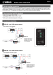
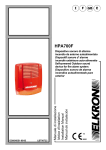
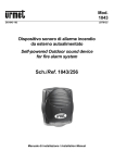
EN
Surface Mount Speaker
FR
ZK28100
English
Owner’s Manual
La version française du Mode d'emploi se trouve au verso.
NOTICE
PRECAUTIONS
PLEASE READ CAREFULLY BEFORE PROCEEDING
* Please keep this manual in a safe place for future reference.
WARNING
Always follow the basic precautions listed below to avoid the possibility of
serious injury or even death from electrical shock, short-circuiting,
damages, fire or other hazards. These precautions include, but are not
limited to, the following:
Do not open
• This device contains no user-serviceable parts. Do not open the device or
attempt to disassemble the internal parts or modify them in any way. If it
should appear to be malfunctioning, discontinue use immediately and have it
inspected by qualified Yamaha service personnel.
Fire warning
• Do not put burning items, such as candles, on the unit. A burning item may fall
over and cause a fire.
CAUTION
Always follow the basic precautions listed below to avoid the possibility of
physical injury to you or others, or damage to the device or other property.
These precautions include, but are not limited to, the following:
Location
• Do not place the device in an unstable position where it might accidentally fall
over.
• Do not place the device in a location where it may come into contact with
corrosive gases or salt air. Doing so may result in malfunction.
• Always consult qualified Yamaha service personnel if the device installation
requires construction work, and make sure to observe the following
precautions.
- Choose mounting hardware and an installation location that can support the
weight of the device.
- Avoid locations that are exposed to constant vibration.
- Use the required tools to install the device.
- Inspect the device periodically.
To avoid the possibility of malfunction/damage to the product or damage to other
property, follow the notices below.
● Handling and maintenance
• Do not expose the device to excessive dust or vibration, or extreme cold or
heat (such as in direct sunlight, near a heater, or in a car during the day), in
order to prevent the possibility of panel disfiguration, unstable operation, or
damage to the internal components.
• Do not place vinyl, plastic or rubber objects on the device, since this might
discolor the panel.
• When cleaning the device, use a dry and soft cloth. Do not use paint thinners,
solvents, cleaning fluids, or chemical-impregnated wiping cloths.
• When turning on the AC power in your audio system, always turn on the
power amplifier LAST, to avoid speaker damage. When turning the power off,
the power amplifier should be turned off FIRST for the same reason.
• Be sure to observe the amplifier’s rated load impedance (see
“Specifications”), particularly when connecting speakers in parallel.
Connecting an impedance load outside the amplifier’s rated range can
damage the amplifier.
• When using a high-impedance speaker connection, make sure the audio
signal is passed through an 80 Hz or above high-pass filter before being input
to the speakers.
• When connecting the speakers with high impedance, be sure that the total
rated input capacity of the speakers does not exceed the output power of the
amplifier.
• Air blowing out of the bass reflex ports is normal, and often occurs when the
speaker is handling program material with heavy bass content.
• Place the speaker on a flat and smooth surface.
• Do not place the speaker on the ground with the grille faced down.
• Do not touch the speaker driver unit.
● Protective circuit
This speaker system has an internal protection circuit that shuts off the speaker
unit when an excessive input signal is applied. If the speaker unit emits no
sound, reduce the volume level of the amplifier immediately. The sound will
return automatically in several seconds.
● About this manual
• The illustrations as shown in this manual are for explanation only, and may
appear somewhat different from your device.
• The company names and product names in this manual are the trademarks or
registered trademarks of their respective companies.
Connections
• Before connecting the device to other devices, turn off the power for all the
other devices. Before turning the power on or off for all devices, set all volume
levels to minimum.
• Use only speaker cables for connecting speakers to the speaker jacks. Use of
other types of cables may result in fire.
Handling caution
• Do not insert your fingers or hands in any gaps or openings on the device
(ports).
• Do not rest your weight on the device or place heavy objects on it.
• Do not operate the device if the sound is distorting. Prolonged use in this
condition could cause overheating and result in fire.
• Do not pull the cables connected.
• When choosing a power amplifier for use with this device, make sure that the
output power of the amplifier is lower than the power capacity of this device
(see “Specifications”).
Even if the output power of the amplifier is lower than the power capacity of
this device (program), use of excessive input signals resulting in clipping may
cause damage to the device.
Malfunction or fire may occur especially when the following sounds or noises
are generated:
- feedback, when using a microphone
- continuous and extreme volume sound from a musical instrument
- extreme continuous distorted sound
- noise caused by plugging/unplugging the cable while the amplifier is turned
on
Information for Users on Collection and Disposal of Old Equipment
This symbol on the products, packaging, and/or accompanying
documents means that used electrical and electronic products
should not be mixed with general household waste.
For proper treatment, recovery and recycling of old products, please
take them to applicable collection points, in accordance with your
national legislation and the Directives 2002/96/EC.
By disposing of these products correctly, you will help to save
valuable resources and prevent any potential negative effects on
human health and the environment which could otherwise arise from inappropriate
waste handling.
For more information about collection and recycling of old products, please contact
your local municipality, your waste disposal service or the point of sale where you
purchased the items.
[For business users in the European Union]
If you wish to discard electrical and electronic equipment, please contact your dealer
or supplier for further information.
[Information on Disposal in other Countries outside the European Union]
This symbol is only valid in the European Union. If you wish to discard these items,
please contact your local authorities or dealer and ask for the correct method of
disposal.
Yamaha cannot be held responsible for damage caused by improper use or
modifications to the device.
Supplied Items
Unpack the contents and confirm that all the following items are included.
• Speaker × 2
• Mounting bracket × 2
• Screw for attaching the mounting bracket × 4
(VXS8-VA/VXS8-VAW: M6 × 14, VXS5-VA/VXS5-VAW: M5 × 14)
• Screw for attaching the terminal cover (4 × 12) × 4
• Safety wire × 2
• Safety pin × 2
• Owner’s Manual (this manual)
• Bracket base × 2
• Bracket cover × 2
• Stopper screw × 2
(M3 × 8, VXS8-VA/VXS8-VAW only)
• Bolt with hexagon hole (M6 × 10) × 2
• Terminal cover × 2
• Hexagon wrench × 1
• Technical Specifications (English only)
* Screws/bolts to fasten the bracket base onto the wall/ceiling and speaker cables are not supplied.
Specifications
Model
Type
Component
VXS8-VA/VXS8-VAW
VXS5-VA/VXS5-VAW
2-way, bass-reflex
LF
8" (20 cm) cone driver
5 1/4" (13 cm) cone driver
HF
1" (2.5 cm) soft dome tweeter
3/4" (2 cm) soft dome tweeter
Coverage angle (–6 dB)*1
Horizontal: 150° (500 Hz), 110° (1 kHz), 110° (2 kHz), 110° Horizontal: 185° (500 Hz), 135° (1 kHz), 110° (2 kHz), 110°
(4 kHz)
(4 kHz)
Vertical: 130° (500 Hz), 105° (1 kHz), 35° (2 kHz),
Vertical: 280° (500 Hz), 115° (1 kHz), 100° (2 kHz),
85° (4 kHz)
100° (4 kHz)
Rated impedance
8 Ω (without transformer)
8 Ω (without transformer)
100 V line: 170 Ω (60 W), 330 Ω (30 W), 670 Ω (15 W)
100 V line: 330 Ω (30 W), 670 Ω (15 W), 1.3 kΩ (7.5 W)
70 V line: 80 Ω (60 W), 170 Ω (30 W), 330 Ω (15 W),
70 V line: 170 Ω (30 W), 330 Ω (15 W), 670 Ω (7.5 W),
670 Ω (7.5 W)
1.3 kΩ (3.8 W)
Power rating
NOISE
90 W
75 W
PGM
180 W
150 W
MAX
360 W
300 W
89 dB (1 W, 1 m, 100 Hz to 10 kHz pink noise)
88 dB (1 W, 1 m, 100 Hz to 10 kHz pink noise)
Sensitivity*1
77 dB (1 W, 4 m, 100 Hz to 10 kHz pink noise)
76 dB (1 W, 4 m, 100 Hz to 10 kHz pink noise)
Maximum SPL*2
106 dB (60 W, 1 m, 100 Hz to 10 kHz pink noise at 60 W 102 dB (30 W, 1 m, 100 Hz to 10 kHz pink noise at 30 W
tap)
tap)
94 dB (60 W, 4 m, 100 Hz to 10 kHz pink noise at 60 W tap) 90 dB (30 W, 4 m, 100 Hz to 10 kHz pink noise at 30 W tap)
115 dB (360 W, 1 m, 100 Hz to 10 kHz pink noise at 8 Ω) 113 dB (300 W, 1 m, 100 Hz to 10 kHz pink noise at 8 Ω)
103 dB (360 W, 4 m, 100 Hz to 10 kHz pink noise at 8 Ω) 101 dB (300 W, 4 m, 100 Hz to 10 kHz pink noise at 8 Ω)
Frequency range (-10 dB)*1, *3
51 Hz – 20 kHz
62 Hz – 20 kHz
Crossover frequency
2.8 kHz
3 kHz
Connector
Ceramic terminal block (3 pin) × 1 (input: +/–, Earth)
Applicable wire size AWG 26–12 (4.0 mm2)
Transformer taps
70 V
60 W, 30 W, 15 W, 7.5 W
30 W, 15 W, 7.5 W, 3.8 W
100 V
60 W, 30 W, 15 W
30 W, 15 W, 7.5 W
Overload protection
Full-range power limiting to protect network and transducers
Magnetically shielded
No
IP35 (EN54-24 Enclosure protection rating. Type B : IP33C)
Dust and water resistant*4, *5
Enclosure
Cabinet
ABS (UL94-5VB)
Baffle
ABS (UL94-5VB)
Grille
Powder coated perforated aluminium (t=1.0 mm), aperture ratio: 51%
Outer color
VXS8-VA/VXS5-VA
Black (approximate value: Munsell N3)
VXS8-VAW/VXS5-VAW White (approximate value: Munsell 9.3)
Dimensions (speaker only)
278 × 430 × 239 mm (11" × 16 15/16" × 9 7/16")
176 × 280 × 163 mm (6 15/16" × 11 1/16" × 6 7/16")
(W × H × D in vertical cabinet orientation)
Net weight (speaker only, 1 piece)
8.2 kg (18.1 lbs)
3.6 kg (7.9 lbs)
Packaging
Packaged in pair
Standards
Certified to the European Standard EN 54-24: 2008 0359-CPR-00406 Certified year: 14
Loudspeaker for voice alarm systems for fire detection and fire alarm systems
Environment type: B
Certified to the European Standard EN60849:1998
Sound systems for emergency purposes
Certified to the International Standard ISO 7240-24: 2010
Sound-system loudspeaker for fire detection and fire alarm systems
In compliance with the British Standard BS-5839-8: 2008 14.8
The specifications data was measured in an anechoic chamber, according to EN 54-24.
Reference axis: Axis is on the center of grille surface and perpendicular to the grille surface.
Reference plane: Plane is on the grille surface and perpendicular to the reference axis.
Horizontal plane: Plane is containing the reference axis and perpendicular to the reference plane.
*1: Full-space (4π)
*2: Calculated based on power rating and sensitivity, exclusive of power compression.
*3: When connecting with low impedance.
*4: IP34 when installing the speaker on the ceiling vertically.
*5: Excluding installation with the grille facing up. Do not install in such a way outside.
The contents of this manual apply to the latest specifications as of the printing date. Since Yamaha makes continuous improvements to the product, this manual
may not apply to the specifications of your particular product. To obtain the latest manual, access the Yamaha website then download the manual file. Since
specifications, equipment or separately sold accessories may not be the same in every locale, please check with your Yamaha dealer.
The dimensions are shown in “Technical Specifications”.
Connecting the Multiple Speakers
1 Installing the Bracket Base on the Wall/ceiling
When installing the multiple speakers, connect them in parallel way.
From amplifier or
previous speakers
To subsequent
speakers
To
subsequent
speakers
Power
amplifier
1.1 Put the bracket base onto the wall/ceiling and mark the position for
the screws/bolts and cables. The diameter of the screw/bolt holes at
the four corners is M6, and speaker cables hole at the center is
ø11 mm.
1.2 Make holes through the wall/
ceiling for the bolts and cables,
as required, and feed the bolts
and cables from the amplifier
through the holes, as shown.
* You can use this terminal to hook up an earth cable, as
necessary.
CAUTION
When connecting with low impedance, take note of the combined
resistance.
Note
When connecting with high impedance, refer to “Better Sound for
Commercial Installations” (English only) of the Yamaha Pro Audio
web site, at the following URL.
http://www.yamahaproaudio.com/global/en/training_support/
better_sound/
Installing the Speakers
Install the speakers on the wall/ceiling with the supplied brackets.
Ensure that the wall/ceiling is sufficiently strong.
Illustrations in this manual are for the VXS5-VA. The installation
method is the same for other models.
1.4 Pass cables through the gap at
the lower part of the bracket
cover, and put the bracket
cover on the bracket base.
Note
If you want to adjust the slack of
cables last, the bracket cover
can be attached after step 5.4.
An installed speaker is shown below. Install the bracket base and
attach the mounting bracket as shown.
Note
• When installing the speaker on the ceiling with the grille parallel to
the ground, install the speaker horizontally.
• When installing the speaker on the ceiling, be sure to install the
bracket base with its shaft facing horizontally, and not inclined to
the ground.
• Mounting bracket is made to not turn left or right when installing the
speaker on the ceiling.
• Refer to the “Technical Specifications” for the angle of installing
speakers.
• Installing with the grille facing up may cause water to enter the
speakers, causing malfunction.
Bracket base
Note
• Guide marked on the mounting bracket is every 10°.
• (VXS8-VA/VXS8-VAW only) When installing the speaker on the
wall with a vertical angle of 30° or less, attach the supplied stopper
screw.
Safety pin
CAUTION
• Make sure to take measures to prevent the speaker from falling
down in the event of an installation failure.
• When installing the safety wire on the wall, install it higher than the
wire’s attachment point on the speaker, with as little slack as
possible.
• If the safety wire is too short, prepare another wire appropriate for
the speaker weight and installation conditions. If the wire is too
long, should the speaker fall, the wire may snap as a result of too
much strain.
Note
The safety pin can be attached from either side of the mounting
bracket depending on the angle of the speaker.
5.3 (If installing the speaker on the wall) turn the speaker horizontally to
set the angle.
5.4 Make sure the mounting bracket is seated against the bracket base,
then tighten the supplied bolt (indication of torque: 6.5 N·m).
4 Connect the Wiring to the Connector
2 Set the Line Voltage/Impedance and Power
Select the line voltage/impedance (100V/70V/8Ω) and power tap for
100V/70V line distributed system, by rotating the tap selector switch
on the rear side of the speaker with a flat-blade screwdriver.
4.1 After loosening the terminal screws of the ceramic terminal with a
driver, insert the cables into each terminal and tighten the screws.
Pull on the cables to make sure they are tightly secured and will not
come loose.
Bolt with hexagon hole
Tap selector switch
+
–
Pre-installation (Preparation of the cable)
Use stranded wire for cables attached to
About 7 mm (0.3")
the ceramic terminal. Strip their insulation
as shown in the figure and connect them.
Note
Do not plate stranded wires by solder. Doing so will cause the wire to
break.
5.2 Attach the safety pin.
Be sure to attach the safety pin to prevent the mounting bracket from
falling.
3.3 Secure the other end of the safety wire to a point close to where the
speaker will be installed.
1.3 Install the bracket base onto
the wall/ceiling. Make sure to
fasten four corners of the
bracket base.
Speaker
Installing on the wall
Bracket cover
3.2 Set the desired vertical angle of the speaker.
Loosen the angle adjustment bolt with the supplied hexagon wrench,
adjust the angle of the speaker, and tighten the angle adjustment bolt
to secure the speaker (indication of torque: 8 N·m).
* You can use this terminal to
hook up an earth cable, as
necessary.
Illustration indicates the setting at 30 W for 100 V
line and 15 W for 70 V line.
Note
• When installing the speaker on the ceiling in particular, make sure
the mounting bracket is seated against the bracket base.
• The bolt with hexagon hole can be attached from either side of the
mounting bracket (left or right) depending on the angle of the
speaker.
The installation is complete.
CAUTION
• The “X” position should not be selected. The 8Ω position should be
selected for 8Ω audio systems only. If the setting is incorrect, it may
cause malfunction of the speaker and amplifier.
• Make sure the amplifier is switched off before operating the tap
selector switch.
3 Attach the Mounting Bracket and Safety Wire
Note
Use a flat-blade screwdriver with a blade less than 3 mm (0.1 in.).
Less than 3 mm (0.1 in.)
4.2 Attach the terminal cover with the screws.
3.1 Attach the mounting bracket and safety wire to the speaker. Use the
supplied screws to attach the mounting bracket.
The way to attach the mounting bracket depends on the orientation of
the speaker (vertical or horizontal).
Screw (4 ×12)
Terminal cover
Vertical installation
Mounting bracket
Installing on the ceiling
Safety wire
Vertical
Angle
adjustment bolt
Stopper screw (M3 × 8)*
5 Install the Speaker on the Bracket Base
5.1 Install the mounting bracket on the bracket base.
Horizontal installation
To the wall
To the ceiling
Stopper screw (M3 × 8)*
Horizontal
Angle adjustment
bolt
Note
Mounting bracket can be attached in reverse direction.
* 8-inch model (VXS8-VA and VXS8-VAW) only.
Yamaha Pro Audio global web site
http://www.yamahaproaudio.com/
Yamaha Manual Library
http://www.yamaha.co.jp/manual/
20141007