1
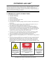
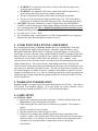
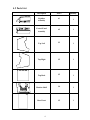
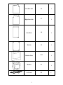
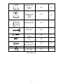
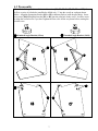
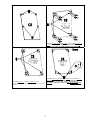
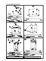
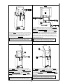
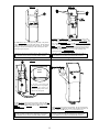
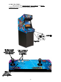
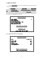
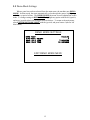
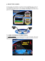
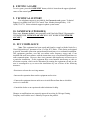
Owner’s Manual
4616 W. 19th Street, Cicero, IL 60804 (800)379-9776
1
(Rev. 1.1)
EXTREME ARCADE
TM
Thank you for purchasing Chicago Gaming Company’s Extreme Arcade. You can look
forward to many hours of video game enjoyment. We strongly recommend that you
follow the instructions and procedures as presented in this Owner’s Manual and that it be
read in its entirety before setting up your game.
1. IMPORTANT SAFETY INSTRUCTIONS
•
•
•
•
•
•
•
•
•
•
•
•
•
Read these instructions.
Keep these instructions.
Heed all warnings.
Follow all instructions.
Do not use this apparatus near water.
Clean only with a dry cloth.
Do not block any ventilation openings. Install in accordance with manufacturer’s
instructions.
Do not install near any heat sources such as radiators, heat registers, stoves, or
other apparatus (including amplifiers) that produce heat.
Do not defeat the safety purpose of the polarized or grounding-type plug. A
polarized plug has two blades with one wider than the other. A grounding type
plug has two blades and a third grounding prong. The wide blade and third prong
are provided for your safety. If the provided plug does not fit into your outlet,
consult an electrician for replacement of the obsolete outlet.
Protect the power cord from being walked on or pinched, particularly at plugs,
convenience receptacles and the point where they exit from the apparatus.
Only use attachments/accessories specified from the manufacturer.
Unplug this apparatus during lightning storms or when unused for long periods of
time.
Refer all servicing to qualified service personnel. Servicing is required when the
apparatus has been damaged in any way, such as power supply cord or plug is
damaged, liquid has been spilled or objects have fallen into the apparatus, the
apparatus has been exposed to rain or moisture, does not operate normally, or has
been dropped.
THE LIGHTNING FLASH
AND ARROWHEAD WITHIN
THE TRIANGLE IS A
WARNING SIGN ALERTING
YOU OF “DANGEROUS
VOLTAGE” INSIDE THE
PRODUCT.
CAUTION: TO REDUCE THE RISK OF
ELECTRIC SHOCK, DO NOT REMOVE
COVER (OR BACK). NO USER
SERVICEABLE PARTS INSIDE. REFER
SERVICING TO QUALIFIED SERVICE
PERSONNEL.
THE EXCLAMATION POINT
WITHIN THE TRIANGLE IS A
WARNING SIGN ALERTING
YOU OF IMPORTANT
INSTRUCTIONS
ACCOMPANYING THE
PRODUCT.
SEE MARKINGS ON PRODUCT
CAUTION: Shock hazard if instructions are not followed.
2
•
•
•
•
•
WARNING: To reduce the risk of fire or electric shock do not expose your
system to rain or moisture.
• WARNING: An apparatus with Class I construction shall be connected to a
main socket outlet with a protective earthing connection.
• Be sure to disconnect the power cable before working on the machine.
• Be sure to use fuses which meet the specified rating. (5A, 220V Quick-blow).
Using fuses exceeding the specified rating can cause a fire and electrical shock.
CAUTION: The game’s monitor is a source of high voltage. Be EXTREMELY
CAREFUL when working near it; high voltage charges can still be present even after
you’ve unplugged the unit. Have a qualified technician perform a monitor repair.
Optimum operating environment is between 50-105° Fahrenheit.
Use with only 115 volts ~ 60Hz
We recommend using a surge suppresser or UPS (Uninterruptible Power Supply) to
safeguard the game from abrupt power spikes or losses
2. ATARI END USER LICENSE AGREEMENT
By accepting and operating an Extreme Arcade, the owner (“End User”) of the unit
agrees to abide by the terms of this agreement. Asteroids, Asteroids Deluxe, Atari
Basketball, Battlezone, Black Widow, Centipede, Cloak and Dagger, Crystal Castles,
Food Fight, Gravitar, Liberator, Lunar Lander, Millipede, Missile Command, Pong, Red
Baron, Skydiver, Space Duel, Super Break-Out, Tempest, Video Pinball, Warlords and
related logos are used under license from Atari Interactive, Inc. (“Atari”). Atari
expressly reserves the sole and exclusive ownership of the aforementioned games and all
rights relating thereto. The end user hereby acknowledges that Atari is the sole and
exclusive owner of the games and licensed trademarks and agrees not to challenge at any
time, directly or indirectly, the rights of Atari. The end user agrees not to attempt to copy
the licensed property (in whole or in part), decompile, disassemble or otherwise reverse
engineer the software in any way. Atari is a third party beneficiary to this agreement and
retains the right to bring action directly against an End User for breach of this End User
License Agreement.
3. WARRANTY INFORMATION
Extreme Arcade is warranted against manufacturing defects for 180 days. After that we
will provide free telephone support. If at some point you require warranty service,
contact Chicago Gaming at (800)379-9776. Ask for technical support.
4. GAME SETUP
4.1 INSTALLATION
• Remove the components from their packaging. Confirm all items listed in the
Parts List (see pages 4 through 6) are present.
• When moving the unit, please treat it as delicately as possible. The monitor is
fragile.
• Be sure to install it in a dry location.
• Plug the machine into a three-prong A/C outlet.
• Please note, the monitor may initially appear discolored, particularly in the
monitor’s corners. This discoloration will go away after it has been powered up a
number of times. You will have to let the unit return to room temperature after
each power cycle for the monitor’s degaussing circuit to clear up this
discoloration.
3
4.2 Parts List
Description
Part #
Quantity
Lightbox
Assembly
A1
1
Control Panel
Assembly
A2
1
Top Left
C1
1
Top Right
C2
1
Top Back
C3
1
Monitor Shelf
C4
1
Base Front
C5
1
4
Left Base Side
C6
1
Right Base Side
C7
1
Base Back
C8
1
Bottom
C9
1
Monitor Glass
C10
Monitor
E1
A/C Cord
E2
5
1
1
1
Standard Angle
Bracket
(Silver)
H1
16
Threaded Angle
Bracket
(Gold)
H2
Leg Side Bracket
H3
4
Leg Leveler
H4
4
H5
6
H6
76
#10-32 x 1-1/4”
Truss Head Screw
H7
24
Nylon Washer
H8
6
Cable Clamp
H9
1
#6 x 1-1/4” Wood
Screw
#10 x 1/2” Wood
Screw
End of Parts List
6
10
4.3 Preassembly
Please find all the parts shown below in this section [C1, C2, C5, C6, C7, C9, H1 and H2]. You
will see a series of pilot holes (small holes drilled only ¼” into the wood) on each part shown
below. Align the appropriate bracket (H1 or H2 as indicated below) with the pilot holes. Screw
two screws [H6] through the bracket [H1 or H2] into the pilot hole in the wood. It will be easier
to align the second screw if you don’t tighten the first screw all the way down before starting the
second screw.
H1 Standard Angle Bracket (Silver)
H2 Threaded Angle Bracket (Gold)
7
Attach H3 Leg Side Bracket to C9 Bottom using (4X4) H6 #10 x ½” Wood
Screws to secure each part. NOTE: BE SURE TO ATTACH H3 Leg
Side Bracket TO THE TOP (SIDE WITHOUT THE GROOVE).
Screw H4 Leg Leveler into H3 Leg Side Bracket. Leave
approximately one inch of thread showing on the side with the Leg
Leveler.
8
Attach H1 Standard Angle Bracket to C9 Bottom using four H6 #10 x ½”
Wood Screws. NOTE: BE SURE TO ATTACH TO THE SIDE WITH
THE GROOVE. DO NOT MOUNT H1 STANDARD ANGLE
BRACKET IN THE PILOT HOLES FOR H3 LEG SIDE BRACKET.
4.4 Assembly Instructions
Step 1
Step 2
Lay C7 Right Base Side on any flat surface; including, a
workbench, table or the floor. Place C9 Bottom perpendicular to
C7 Right Base Side. BE SURE TO ORIENT THE GROOVED
SIDE OF C9 IN THE PROPER DIRECTION. Align the
protruding metal tab in H3 Leg Side Bracket into the slots at the
bottom of C7 Right Base Side. Further align the hole in H3 Leg
Side Bracket with the pilot holes in C7 Right Base Side and secure
with H6 #10 x ½” Wood Screw. Only one H6 #10 x ½” Wood
Screw is needed to secure each H3 Leg Side Bracket.
Place C5 Base Front in the progressing assembly. Align the holes in the
brackets with the appropriate pilot holes and secure with three H6 #10 x ½”
Wood Screw.
Step 3
Step 4
Place C6 Left Base Side on the progressing assembly. Align the
holes located in C6 Left Base Side with H3 Leg Side Bracket and
H2 Treaded Angle Bracket and secure with H7 #10-32 x 1-1/4”
Truss Head Screw. Before tightening screws, force C6 Left Base
Side toward the floor side of the assembly.
Place the assembly in its upright position on the floor. Adjust H4 Leg
Leveler to a height that keeps the sides of the assembly off the ground.
Screw H7 #10-32 x 1-1/4” Truss Head Screw through C7 Right Base Side
into H3 Leg Side Bracket.
Step 5
Step 6
Place A2 Control Panel Assembly onto the progressing assembly
and secure with H7 #10-32 x 1-1/4” Truss Head Screws. Make sure
A2 Control Panel Assembly is centered in the progressing
assembly. Attach H9 Cable Clamp to A2 Control Panel Assembly
with H6 #10 x 1/2” Wood Screw. This will secure the power cord
from coming unplugged from A2 Control Panel Box.
Place C4 Monitor Shelf onto the progressing assembly. Use C4 Monitor
Shelf to confirm the progressing assembly is square. If the progressing
assembly is not square, you may need to slightly loosen the H7 #10-32 x 11/4” Truss Head Screws that were previously utilized and then force
assembly square. Once the progressing assembly is square, insert H5 #6 x
1-1/4” Wood Screw through C4 Monitor Shelf into the pilot holes in C6
Left Base Side and C7 Right Base Side and tighten down. BE CERTAIN
SCREWS ENTER THE PILOT HOLES.
TAKE GREAT CARE NOT TO PINCH ELECTRICAL WIRES AND CORDS. IF
ELECTRICAL WIRES OR CORDS ARE INADVERTENTLY DAMAGED, DO
NOT USE THEM! CONTACT MANUFACTURER FOR REPLACEMENT.
TAKE GREAT CARE NOT TO PINCH ELECTRICAL WIRES AND CORDS. IF
ELECTRICAL WIRES OR CORDS ARE INADVERTENTLY DAMAGED, DO
NOT USE THEM! CONTACT MANUFACTURER FOR REPLACEMENT.
9
Step 7
Step 8
Remove E1 Monitor from its box and place it on the progressing
assembly. The monitor should be centered between the two cleats
and pushed all the way to the back of the game. Pull the monitor
A/C Cable, VGA Cable and Speaker/Lamp Cable through the
Cable Routing Hole in C4 Monitor Shelf.
TAKE GREAT CARE NOT TO PINCH ELECTRICAL WIRES AND CORDS. IF
ELECTRICAL WIRES OR CORDS ARE INADVERTENTLY DAMAGED, DO
NOT USE THEM! CONTACT MANUFACTURER FOR REPLACEMENT.
Connect the Monitor A/C Cable, which extends from A2 Control Panel
Assembly to the back of the monitor. Connect the VGA Cable, which
extends from A2 Control Panel Assembly to the VGA cable extending from
the back of the monitor. Plug E2 A/C Cord into the back of A2 Control
Panel Assembly. Temporarily plug the A/C cable into your wall outlet.
Turn the power switch on (located at the front, bottom right side of the
control panel assembly). Confirm system powers up. If monitor does not
turn on, press power button on the monitor. Following the instructions
included with the monitor, center the image and set brightness to 75 (or
whatever setting looks best to you). After you have adjusted the monitor,
unplug the unit from the wall.
TAKE GREAT CARE NOT TO PINCH ELECTRICAL WIRES AND CORDS. IF
ELECTRICAL WIRES OR CORDS ARE INADVERTENTLY DAMAGED, DO
NOT USE THEM! CONTACT MANUFACTURER FOR REPLACEMENT.
Step10
Step 9
Set C2 Top Right on the progressing assembly. The four H1 Standard
Angle Brackets located on Top Right are there only to help position the part
while you install H7 #10-32 x 1-1/4” Truss Head Screws (no screws will
pass through the open holes in the four H1 Standard Angle Brackets). Be
sure to use H8 Nylon Washer on the screws passing through C2 Top Right.
The nylon washers help protect the artwork (decals) from being damaged
by the screws.
Set C1 Top Left on the progressing assembly. The four H1
Standard Angle Brackets located on C1 Top Left are there only to
help position the part while you install H7 #10-32 x 1-1/4” Truss
Head Screws (no screws will pass through the open holes in the
four H1 Standard Angle Brackets). Be sure to use H8 Nylon
Washer on the screws passing through C1 Top Left. The nylon
washers help protect the artwork (decals) from being damaged by
the screws.
TAKE GREAT CARE NOT TO PINCH ELECTRICAL WIRES AND CORDS. IF
ELECTRICAL WIRES OR CORDS ARE INADVERTENTLY DAMAGED, DO
NOT USE THEM! CONTACT MANUFACTURER FOR REPLACEMENT.
10
TAKE GREAT CARE NOT TO PINCH ELECTRICAL WIRES AND CORDS. IF
ELECTRICAL WIRES OR CORDS ARE INADVERTENTLY DAMAGED, DO
NOT USE THEM! CONTACT MANUFACTURER FOR REPLACEMENT.
Step 12
Step 11
Set C10 Monitor Glass in the progressing assembly. The painted
side should face toward the inside of the cabinet. The side marked
“TOP” should of course be positioned toward the top. The bottom
of the glass should sit behind the top of the control panel, which
will trap the glass into place.
TAKE GREAT CARE NOT TO PINCH ELECTRICAL WIRES AND CORDS. IF
ELECTRICAL WIRES OR CORDS ARE INADVERTENTLY DAMAGED, DO
NOT USE THEM! CONTACT MANUFACTURER FOR REPLACEMENT.
Step 13
SLOWLY and CAREFULLY set A1 Lightbox Assembly on top of the
progressing assembly being careful not to break C10 Monitor Glass. The
front of A1 Lightbox Assembly should sit in front of the glass and trap it in
place. Attach A1 Lightbox Assembly with H7 #10-32 x 1-1/4” Truss Head
Screws. Be sure to use H8 Nylon Washer on the screws passing through C2
Top Right and C1 Top Left. The nylon washers help protect the artwork
(decals) from being damaged by the screws. Connect the Speaker Cable,
which extends from A1 Lightbox Assembly to the remaining cable
extending from A2 Control Panel Assembly.
TAKE GREAT CARE NOT TO PINCH ELECTRICAL WIRES AND CORDS. IF
ELECTRICAL WIRES OR CORDS ARE INADVERTENTLY DAMAGED, DO
NOT USE THEM! CONTACT MANUFACTURER FOR REPLACEMENT.
Step 14
Attention Required!
Out of
Square
If the unit is not square, C8
Base Back will not fit properly.
Make sure leg levelers are
adjusted properly, loosen screws
and force the unit square.
Set C8 Base Back in the progressing assembly. Make sure E2 A/C
Cord passes through the opening in the lower left corner of C8
Base Back. Secure C8 Base Back with four H7 #10-32 x 1-1/4”
Truss Head Screws.
TAKE GREAT CARE NOT TO PINCH ELECTRICAL WIRES AND CORDS. IF
ELECTRICAL WIRES OR CORDS ARE INADVERTENTLY DAMAGED, DO
NOT USE THEM! CONTACT MANUFACTURER FOR REPLACEMENT.
11
Set C3 Top Back in the progressing assembly. Be sure to position the
ventilation slots toward the top and the tongue toward the inside of the
cabinet. Attach with H7 #10-32 x 1-1/4” Truss Head Screws.
TAKE GREAT CARE NOT TO PINCH ELECTRICAL WIRES AND CORDS. IF
ELECTRICAL WIRES OR CORDS ARE INADVERTENTLY DAMAGED, DO
NOT USE THEM! CONTACT MANUFACTURER FOR REPLACEMENT.
4.5 KEY FEATURES
The locations of the On/Off Switch, Service Button, and Display
Adjustment Panel are shown in the illustration below.
12
5. SERVICE MENU
Press the Service Button, which is located underneath the control panel, just next
to the power switch.
The Service Menu provides access to Main Volume control, the Game Settings
sub-menu, the Controller Tests sub-menu, Display Convergence Test, Display Color
Test, and the Demo Mode Settings sub-menu. To change the main volume, use the
joystick on the Player One side (left joystick) to highlight Main Volume, and then move
joystick right to turn the volume up, or left to turn the volume down. To select any of the
other options on screen, highlight using the joystick, and press button 1 (the furthest left
blue button) on the Player One side (left side).
SERVICE MENU
MAIN VOLUME
GAME SETTINGS
CONTROLLER TESTS
DISPLAY CONVERGENCE TEST
DISPLAY COLOR TEST
DEMO MODE SETTINGS
7
EXIT SERVICE MENU
VERSION: 1.02
BUILD DATE: SEP 03 2007
5.1 GAME SETTINGS SUB-MENU
GAME SETTINGS
GAME
ALPINE SKI
BONUS LIFE
FREE PLAY
LIVES
SERVICE MODE
INVULNERABILITY
10K
OFF
3
OFF
OFF
RESET TO DEFAULTS
EXIT TO SERVICE MENU
13
The Game Settings sub-menu allows adjustments of several different aspects of
game play. Optional settings differ between games. Note: Alpine Ski is shown on the
previous page as an example. To select the game for which settings are being adjusted,
highlight GAME with the joystick on the Player One side and move the joystick right or
left to choose a game. To change the settings, such as how many points are required for a
bonus life, or with how many lives a player begins, highlight the specified option with the
joystick, and move joystick right or left to choose different settings.
5.2 Controller Tests
The CONTROLLER TESTS sub-menu allows you to confirm the buttons and
joysticks are functioning correctly. Use of any of the controls should highlight the button
or direction pressed in the menu shown below. Should any control cease to work, contact
technical support. Each of the controls can be replaced in a matter of minutes with only a
Phillips head screwdriver and a nut driver. To exit CONTROLLER TESTS, press
Player 1 Start and Player 2 Start and the same time.
CONTROLLER TESTS
PLAYER 1
PLAYER 2
UP
DOWN
LEFT
RIGHT
BUTTON 1
BUTTON 2
BUTTON 3
START P1
UP
DOWN
LEFT
RIGHT
BUTTON 1
BUTTON 2
BUTTON 3
START P2
GENERAL
MENU
TEST
P1 AND P2 START EXITS
5.3 Display Convergence Test
Selecting this option displays a test pattern, which assists in adjusting the monitor.
5.4 Display Color Test
This option displays a color test, which assists in adjusting the monitor.
14
5.5 Demo Mode Settings
When a game has not been selected from the main menu, the machine runs DEMO
MODE. In demo mode, the menu automatically cycles through the games, highlighting
each for a set period of time. The DEMO MODE sub-menu accesses adjustments to this
mode. To change settings in DEMO MODE, highlight any option with the left joystick,
and move joystick right or left to toggle between choices. To return to the main menu,
select EXIT DEMO MODE MENU with the joystick, and press button 1 (the far left
blue button).
DEMO MODE SETTINGS
DEMO
DEMO
GAME
MENU
MODE
MODE VOLUME
IDLE TIME
IDLE TIME
ENABLED
7
2 MINUTES
15 SECONDS
EXIT DEMO MODE MENU
15
6. SELECTING GAMES
To select a game, move the Player 1 joystick up or down to highlight a game. Once you
have highlighted the game that you wish to play, press the Player 1 Start Button if you
wish to start a single player game, or press the Player 2 Start Button if you wish to start a
game for two players.
7. GAME CONTROLS INSTRUCTIONS
The GAME CONTROLS screen is displayed before the start of each game. This screen
explains which controls are utilized in each game. To exit this screen before the default
allotted time, press any button.
16
8. EXITING A GAME
To exit a game, press the GAME EXIT button, which is located on the upper right hand
corner of the control panel.
9. TECHNICAL SUPPORT
Free telephone support is provided for the Extreme Arcade system. Technical
Support is available from 9:00-5:00 Central Time, Monday through Friday. Call
1(800)379-9776. Select technical support in phone system menu.
10. GAMEPACK (UPGRADES)
Please note, Extreme Arcade is not compatible with UltraCade/Global VR gamepacks.
UPGRADES FOR ULTIMATE ARCADE WILL NOT WORK WITH EXTREME
ARCADE!!!
11. FCC COMPLIANCE
Note: This equipment has been tested and found to comply with the limits for a
Class B digital device, pursuant to Part 15 of the FCC Rules. These limits are designed
to provide reasonable protection against harmful interference in a residential installation.
This equipment generates, uses and can radiate radio frequency energy and, if not
installed and used in accordance with the instructions, may cause harmful interference to
radio communications. However, there is no guarantee that interference will not occur in
a particular installation. If this equipment does cause harmful interference to radio or
television reception, which can be determined by turning the equipment off and on, the
user is encouraged to try to correct the interference by one of more of the following
measures:
--Reorient or relocate the receiving antenna.
--Increase the separation between the equipment and receiver.
--Connect the equipment into an outlet on a circuit different from that to which the
receiver is connected.
--Consult the dealer or an experienced radio/technician for help.
Changes or modifications not expressly approved in writing by Chicago Gaming
Company could void the user’s authority to operate the product.
17
18