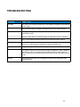
1
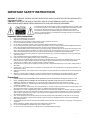
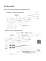
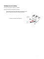
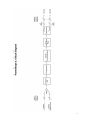
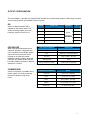
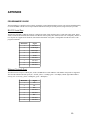
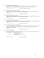
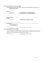
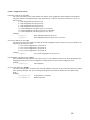
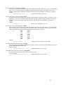
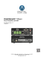
POWERSHAPE™ PS-2.1
Class D Amplifier with DSP
User Manual Version 1.2
11/19/2013
DIGITAL AUDIO LABS - 1266 Park Road - Chanhassen, MN 55317
[email protected] (952) 401-7700
www.digitalaudio.com
This page intentionally left blank
2
IMPORTANT SAFETY INSTRUCTIONS!
4
WHAT’S IN THE BOX!
5
CONNECTIONS!
6
FRONT PANEL!
6
REAR PANEL!
6
INSTALLATION !
7
GENERAL INSTRUCTIONS!
8
TERMINAL BLOCK WIRING!
9
BLOCK DIAGRAM!
10
INPUT CONFIGURATION!
11
OUTPUT CONFIGURATION!
12
EQ!
12
CROSSOVER!
12
COMPRESSOR!
12
STEREO ENHANCEMENT!
13
MASTER OUTPUT VOLUME!
13
CONTROL AND SETUP OPTIONS!
14
USB!
14
RS-232!
14
ETHERNET!
14
INFRARED (IR)!
14
PRESETS!
14
POWER SAVE MODE!
14
SOFTWARE CONFIGURATION!
15
AUDIO PROCESSING!
15
COMMUNICATION STATUS!
15
SERIAL (RS-232) CONFIGURATION!
16
NETWORK (ETHERNET) CONFIGURATION!
16
SAVE, LOAD AND PRESETS!
16
NEW, OPEN AND SAVE!
16
FACTORY PRESETS!
16
USER PRESETS!
16
FIRMWARE UPDATE!
16
HELP!
16
USER MAINTENANCE!
17
ENVIRONMENTAL CONSIDERATIONS!
17
CLEANING!
17
WARRANTY AND SERVICE!
18
TECHNICAL SPECIFICATIONS!
19
APPENDIX!
20
PROGRAMMER’S GUIDE!
20
TROUBLESHOOTING!
37
3
IMPORTANT SAFETY INSTRUCTIONS
WARNING: TO REDUCE THE RISK OF FIRE OR ELECTRIC SHOCK, DO NOT EXPOSE THIS APPLIANCE TO
RAIN OR MOISTURE.
CAUTION: TO REDUCE THE RISK OF ELECTRIC SHOCK, DO NOT REMOVE COVER. NO USER SERVICEABLE PARTS INSIDE. REFER SERVICING TO QUALIFIED SERVICE PERSONNEL.
The lightning flash with arrowhead symbol, within an equilateral triangle, is intended to alert
the user to the presence of un-insulated “dangerous voltage” within the products enclosure
that may be of sufficient magnitude to constitute a risk of electric shock to persons.
The exclamation point within an equilateral triangle is intended to alert the user to the
presence of important operating and maintenance (servicing) instructions in the literature
accompanying the appliance.
Important Safety Instructions:
1.
2.
3.
4.
5.
6.
Read and understand this entire manual.
Keep this manual available for reference.
Heed all warnings and precautions in this manual and notices marked on the product.
Do not use this product near water or damp environments.
Do not block any ventilation openings. Install in accordance with the manufacturer’s instructions.
Do not install near any heat sources such as radiators, heat registers, stoves, or other products (including amplifiers) that produce
heat or other high ambient temperature environments. Provide for proper airflow around product.
Do not defeat the safety purpose of the polarized or grounding-type plug. A polarized plug has two blades with one wider than the
other. A grounding type plug has two blades and a third grounding prong. The wide blade or the third prong is provided for your
safety. If the provided plug does not fit into your outlet, consult an electrician for replacement of the obsolete outlet.
Protect the power cord from being walked on or pinched particularly at plugs, convenience receptacles, and the point where they
exit from the product.
Only use attachments/accessories specified by the manufacturer.
Unplug this product during lightning storms or when unused for long periods of time.
Refer all servicing to qualified service personnel. Servicing is required when the product has been damaged in any way, such as
power-supply cord or plug is damaged, liquid has been spilled or objects have fallen into the product, the product has been
exposed to rain or moisture, does not operate normally, or has been dropped.
The product shall not be exposed to dripping or splashing and that no objects filled with liquids, such as vases, shall be placed on
the product.
Power Sources - The product should be connected to a power supply only of the type described in the operating instructions or as
marked on the product.
Object and Liquid Entry - Care should be taken so that objects do not fall and liquids are not spilled into the enclosure through the
openings.
Servicing - The user should not attempt to service the appliance beyond that described in the operating instructions. All other
servicing should be referred to qualified service personnel. There are no user serviceable components inside the product.
7.
8.
9.
10.
11.
12.
13.
14.
15.
Precautions:
1.
2.
POWER CORD NOTICE FOR INTERNATIONAL OPERATION - Please call Digital Audio Labs Support at (952) 471-7700.
Power – WARNING, BEFORE TURNING ON THE POWER FOR THE FIRST TIME, READ THE FOLLOWING SECTION
CAREFULLY. All models are designed for use only with the power supply voltage of the region where they are sold.
Voltage Label (Rear Panel) – A label located on the power supply indicates the AC power input for the unit. The label will read
100-240V AC, 50/60Hz, 1.4A.
Do not touch the PS-2.1 with wet hands. Do not handle the PS-2.1 or power cord when your hands are wet or damp. If water or any
other liquid enters the PS-2.1 cabinet, take the PS-2.1 to qualified service personnel for inspection.
Place the PS-2.1 in a well, ventilated location. Take special care to provide plenty of ventilation on all sides of the PS-2.1 especially
when it is placed in an audio rack. If ventilation is blocked, the PS-2.1 may over heat and malfunction. Do not expose the PS-2.1 to
direct sun light or heating units as the PS-2.1 internal components temperature may rise and shorten the life of the components.
Avoid damp and dusty environments.
Care – From time to time you should wipe off the front and side panels and the cabinet with a dry soft cloth. Do not use rough
material, thinners, alcohol or other chemical solvents or cloths since this may damage the finish or remove the panel lettering.
Class II wiring required.
The manufacturer cannot be held responsible for damages caused to persons, things or data due to an improper or missing ground
connection.
Before powering this amplifier, verify that the correct voltage rating is being used.
Do not use this amplifier if the electrical power cord is frayed or broken.
Do not remove the cover. Failing to do so will expose you to potentially dangerous voltage.
3.
4.
5.
6.
7.
8.
9.
10.
11.
4
WHAT’S IN THE BOX
1. PowerShape 2.1 - Class D Amplifier with DSP
2. Power Supply (24VDC 2.5A)
3. IEC Power Cable (6’ Length)
4. USB Cable (6’ Length)
5. Quick Start Guide
Visit www.digitalaudio.com/powershape for the latest PowerShape 2.1 configuration software and documentation.
5
CONNECTIONS
FRONT PANEL
1 - Power Indicator
2 - USB
REAR PANEL
1 - 24VDC Power Input
5 - Digital Optical Input (Stereo)
2 - Subwoofer Output
6 - RS-232
3 - Speaker Outputs (Left/Right)
7 - Digital Coax Input (Stereo)
4 - Ethernet
8 - Analog Inputs (Stereo)
6
INSTALLATION
There are two factory presets for quick setup: Conference/Classroom #1 & #2.
7
GENERAL INSTRUCTIONS
•
•
•
•
•
Review safety warnings on page 4 before preceding.
Use only the included 24VDC power supply and power cable.
Surge protector or power conditioner recommended.
Leave adequate space on rear and sides for proper ventilation.
Only plug this device into a grounded outlet.
8
TERMINAL BLOCK WIRING
A full set of terminal block connectors is included.
General instructions for terminal block connectors:
!
!
Strip the wire 1⁄4 inch (6 mm) and connect to the plugs as shown.
Be sure to tighten the screws with a flathead screw driver.
SPEAKER
OUTPUT
Connector Part Number: OSTTJ020150
9
BLOCK DIAGRAM
10
INPUT CONFIGURATION
The PowerShape 2.1 offers both stereo analog and stereo digital inputs.
• Analog Input -10dBV (RCA style connectors)
• Digital Input (S/PDIF Coax or Toslink Optical, only one active at a time)
All inputs in the system offer channel specific volume offsets that can be adjusted from -64.0dB to 0.0dB in 0.5dB
steps (note: 0.0dB is full volume). Analog and digital inputs can also be muted independently.
11
OUTPUT CONFIGURATION
The PowerShape 2.1 provides Left, Right and Sub speaker level, terminal block outputs. A wide range of volume
and processing controls are available to tune the system.
EQ
A stereo 5-Band parametric EQ is
available on the master output. This
audio processing shapes the overall
frequency response of the PS-2.1.
CROSSOVER
When using both high frequency and
subwoofer speakers, a high pass filter
can be inserted on the left/right speaker
outputs and a low pass filter can be
inserted on the subwoofer output.
Additional controls include a 40Hz high
pass filter and speaker offsets that can
be used to balance the levels of different
speakers in a system.
COMPRESSOR
A stereo compressor is available on the
master output. This audio processing
reduces the dynamic range of the
PS-2.1.
EQ BAND
FILTER TYPE
FREQUENCY
Q
Low
Shelving +/- 12dB in 0.5dB steps
Mid 1
Peak/Dip +/- 12dB in 0.5dB steps
Variable
Variable
Mid 2
Peak/Dip +/- 12dB in 0.5dB steps
Variable
Mid 3
Peak/Dip +/- 12dB in 0.5dB steps
31 Frequency
Band Options
High
Shelving +/- 12dB in 0.5dB steps
0.707 Fixed
Variable
0.707 Fixed
CROSSOVER PARAMETER
DESCRIPTION
Filter
None, Low Pass, High Pass
Type
Butterworth, Linkwitz-Riley, Bessel
Frequency
20Hz to 20kHz in 1Hz steps
40Hz High Pass
On/Off
L/R and Sub Speaker Offsets
-64dB to 0.0dB in 0.5dB steps
COMPRESSION PARAMETER
RANGE
Threshold
-64.0 to 0.0 in 0.5dB steps
Ratio
1.0:1 to 10.0:1 in 0.1 steps
Attack
0ms to 500ms in 1ms steps
Release
0ms to 2500ms in 1ms steps
Makeup Gain
0 to 24dB in 0.5dB steps
12
STEREO ENHANCEMENT
A stereo enhancement features is available on the master output. Use this control to increase the stereo image of
your system when speaker placement is close or a wider stereo field is desired. When this feature is configured to
mono, a uniform input is distributed to all outputs, perfect for multi-zone installations requiring the same signal in
different zones.
MASTER OUTPUT VOLUME
The master output of the system can be adjusted from –Inf (-64.0dB) to +24dB in 0.5db steps. The master output
volume can also be muted.
13
CONTROL AND SETUP OPTIONS
The PowerShape 2.1 offers several control options including USB, RS-232, Ethernet and Infrared. If this is your
first time using this device it is recommended that you download the latest PowerShape 2.1 configuration software
from www.digitalaudio.com/powershape and connect via USB to access the real time controls of the PS-2.1. See
the Programmer’s Guide (p. 20) for detailed programming commands to control all parameters of the PS-2.1.
USB
The PowerShape 2.1 configuration software provides access to all controls, settings and if necessary, firmware
update. When using an external control system, this software can be used to configure and test the PS-2.1. The
configuration software provides real-time control of all parameters.
RS-232
The RS-232 port provides an interface between a PC or control system and the PS-2.1. A straight wired 9pin male
to female serial cable is required. See the Programmer’s Guide Appendix (p. 20) for more information.
ETHERNET
The Ethernet port is used to configure, monitor, and control the PS-2.1 via standard 10Base-T and 100Base-TX
Ethernet speeds. Use an Ethernet crossover cable to connect the PS-2.1 directly to a computer. Use a standard
(non-crossover) Ethernet cable if the PS-2.1 and computer are connected indirectly using an Ethernet repeater
hub or switch. All devices connected to the Ethernet port, including repeater hubs, switches,and the computer’s
Network Interface Card (NIC) must support 10Base-T or 100Base-T communication. See the Programmer’s
Guide Appendix (p. 20) for more information.
INFRARED (IR)
The PowerShape 2.1 has a built in IR receiver that is accessible through the front panel. Master output volume
controls (UP, DOWN, MUTE) can be adjusted with an IR remote control. See the Programmer’s Guide Appendix
(p. 21) for more information.
PRESETS
Three factory presets can be loaded in the PowerShape 2.1 configuration software or via command over RS-232
or Ethernet. The factory presets provide examples of how to configure the output for 2.0 stereo, 3.0 monaural and
2.1 stereo with a sub.
Four user presets can be saved and loaded in the PowerShape 2.1 configuration software or via command over
RS-232 or Ethernet. The user presets provide easy recall to many settings at once, and can greatly simplify
programming in environments that have repeatable conditions.
POWER SAVE MODE
Power save settings can be configured with the PowerShape 2.1 configuration software or via command over
RS-232 or Ethernet. The threshold control sets the audio trigger level for this feature. The delay control sets the
amount of time audio needs to be absent, below the threshold, before the PS-2.1 enters power save. By default
this feature is turned off.
!
!
When the PS-2.1 is idle, power save mode cuts the power consumption in half.
!
6 Watts Idle Power (not in power save mode)
!
3 Watts Idle Power (power save mode)
14
SOFTWARE CONFIGURATION
The PowerShape 2.1 configuration software provides real time control of all audio and control parameters. Most
editable parameters are presented on a single screen for quick, intuitive access. The application can be run in
standalone mode without a PS-2.1, or it can control a PS-2.1 via USB, Serial (RS-232) or Network (Ethernet).
The latest version of this software is available at www.digitalaudio.com/powershape.
AUDIO PROCESSING
See the Block Diagram, Input Configuration and Output Configuration sections of the manual for operational
information related to the audio processing.
COMMUNICATION STATUS
When the configuration software is connected to a PS-2.1 via USB, Serial or Network the corresponding green
indicator will illuminate. If using the serial connection, configure the port and select the connect button. If using the
network connection, configure the IP address and select the connect button.
15
SERIAL (RS-232) CONFIGURATION
Additional serial port configuration settings are located within the Communication section of the menu bar. Serial
settings can be configured in this box.
NETWORK (ETHERNET) CONFIGURATION
Additional network port configuration settings are located within the Communication section of the menu bar.
Network settings can be configured in this box.
SAVE, LOAD AND PRESETS
The Presets section of the menu bar provides options to open and save configuration files and load and save
presets.
NEW, OPEN AND SAVE
New: Performs a full reset of the settings in the application.
Open: Load an existing .xml configuration file. Perfect for installs that require multiple PS-2.1’s with the same
settings.
Save/Save As: Save the currently selected configuration settings to a file on your computer. Perfect for backup or
duplicating your PS-2.1 configuration in another unit.
FACTORY PRESETS
Three factory presets can be loaded: 2.0 stereo, 3.0 monaural and 2.1 stereo with a sub. These are baseline
presets that are intended to be edited further.
USER PRESETS
Four user presets can be saved and loaded. The user presets provide easy recall to many settings at once, and
can greatly simplify programming in environments that have repeatable conditions.
FIRMWARE UPDATE
The Advanced section of the menu bar provides a firmware update option. The latest PowerShape 2.1 firmware
version is available at www.digitalaudio.com/powershape.
HELP
The Help section of the menu bar provides the ability to see current version of the PowerShape configuration
software. This version is located in the lower left corner of the box in a X.X.X.X format. If a PowerShape 2.1 is
connected to the computer the Main CPU section will display the firmware version of the unit.
16
USER MAINTENANCE
ENVIRONMENTAL CONSIDERATIONS
The biggest factor in the lifetime of any electronic device is excess heat. The PowerShape 2.1 is designed to
handle any of the heat produced internally, but external sources of heat should be taken into account when
installing the PS-2.1.
If the PS-2.1 is installed in an enclosed equipment rack or closet ensure that the ambient temp of the space with
the equipment running remains below 90 degrees Fahrenheit.
Dust build up inside the unit can cause excess heat buildup. It is a good idea to keep the operating environment
as clean and dust free as possible.
CLEANING
Before cleaning any part of the PS-2.1, disconnect the power supply. Use a soft cloth and mild non-abrasive
solution to clean the faceplates and chassis.
WARNING - Never let any liquid reach the internal parts of the amplifier.
17
WARRANTY AND SERVICE
DIGITAL AUDIO LABS LIMITED WARRANTY
Digital Audio Labs warrants their products against defects in material and workmanship for a period of two years
from date of purchase. During this period, Digital Audio Labs will, at its option, repair the defective unit or replace
it with a new or rebuilt one.
The warranty does NOT cover:
• Damage due to abuse, misuse, or accident.
• Damage due to operation contrary to the instructions in the product instruction manual.
• Units on which the product serial number has been removed or altered.
• Units that have been serviced by unauthorized personnel.
All implied warranties, including warranties on merchantability and fitness, are limited in time to the length of this
warranty. Some states do not allow time limitations on implied warranties, so this limitation may not apply to you.
Digital Audio Labs' liability is limited to the repair or replacement of its product. Digital Audio Labs shall in no way
be held liable for incidental or consequential damages resulting from the use of their product or its software,
including, without limitation, damages from loss of business profits, business interruption, loss of business
information or other pecuniary loss. Some states do not allow the exclusion or limitation of incidental or
consequential damages, so the above limitation or exclusion may not apply to you.
REPAIR POLICY
Please do not return the product without obtaining an RMA number first. Contact Digital Audio Labs at
[email protected] to acquire an RMA number. Do not return the product to the place of purchase. Please
write the RMA number on the outside of the shipping carton. Any product sent to us without a valid RMA number
will be refused. Include the following with the product: a brief description of the problem, your name, return
shipping address, phone number and the RMA number. Do not include any accessories. DAL is not responsible
for any damage to or loss of the product during transit. We recommend that customers obtain a receipt and
tracking number for all packages shipped to us. Turnaround time on repairs is generally ten business days. If you
live outside of the United States, please contact your local distributor for warranty service.
Please return product to:
Digital Audio Labs
Attn: RMA Number
1266 Park Road
Chanhassen, MN 55317
USA
WARRANTY SERVICE
You will be required to pay the shipping charges when you ship your product to DAL. DAL will pay for return
shipping via UPS ground. We reserve the right to inspect any product that may be the subject of any warranty
claim before repair is carried out. For warranty service, we may require proof of the original date of purchase if
you have not registered your product with DAL. Final determination of warranty coverage lies solely with Digital
Audio Labs. Please refer to the warranty information included in this help file.
NON-WARRANTY SERVICE
If it is determined that the product does not meet the terms of our warranty, you will be billed for labor, materials,
return freight and insurance. There is a $50 USD minimum charge for materials and labor. Appropriate shipping
charges will be applied. We require payment in advance of repair by credit card; we accept Visa and Master Card.
In the event the charges are over the minimum charge, DAL will contact you and inform you of the cost of the
repair before any work is completed.
18
TECHNICAL SPECIFICATIONS
POWERSHAPE™ PS-2.1
Parameter
Specification
Notes
Speaker Outputs
Frequency Response
20Hz to 20kHz
+0, -3dB
>90 dB
A-weighted, typical
HF Output Power (2)
20 Watts
4-8 Ω Stereo
Sub Output Power (1)
25 Watts
4-8 Ω Stereo
HF THD+N
0.16%*
20 watts into 8Ω, 20-20kHz
Sub THD+N
0.02%*
25 watts into 8Ω, 20-20kHz
-10dBV
10 kΩ Input Impedance
Dynamic Range
Analog Input (Stereo)
Digital Inputs (Stereo)
Stereo S/PDIF Coax or Optical
Infrared (IR)
38kHz
Front Panel IR Receiver
Compressors
Equalizers
User Adjustable
Digital Signal Processing (DSP)
Crossovers
System Control
Ethernet, RS-232, USB
External Power Supply
24VDC, 60W
Box Dimensions
5.45” W x 1.75” H x 6.8” D
Weight
1.25 lb. (0.57 kg)
*THD+N measurements taken with a 180Hz 2nd order crossover.
19
APPENDIX
PROGRAMMER’S GUIDE
The PowerShape 2.1 amplifier can be remotely operated by control and automation systems, such as those manufactured by
Crestron and AMX. One RS-232 serial port and one Ethernet network port (Telnet protocol, single client) are provided.
RS-232 Serial Port
The RS-232 serial port is a DE-9F connector, configured as DCE. Serial port data rates of 1200, 2400, 4800, 9600, 19200,
38400, 57600 and 115200 baud, data formats of 8 data bits with no parity and 7 data bits with even or odd parity, and one or
two stop bits are supported. The baud rate, data format and number of stop bits is configurable from the PC GUI or with
program commands.
DE-9F Pin
Signal
1
not used
2
TxD output
3
RxD input
4
not used
5
GND
6
not used
7
not used
8
not used
9
not used
Ethernet Network Port
The Ethernet network port is a RJ45 jack, wired as an MDI device. Both 10Base-T and 100Base-TX speeds are supported.
The left LED indicates the link speed (off = no link, yellow = 10 Mbps, green = 100 Mbps), and the right LED indicates
activity (off = no activity, yellow = halfduplex, green = fullduplex).
!
!
!
RJ45 Pin
Signal
1
TX +
2
TX –
3
RX +
4
not used
5
not used
6
RX –
7
not used
8
not used
!
!
!
!
!
!
!
!
!
20
The network port supports IPv4. The network port's IP address can assigned dynamically by a DHCP or BOOTP server,
assigned dynamically using 169.254.xxx.yyy link-local addressing (AutoIP / RFC 3927) when there is no DHCP or BOOTP
server available (not recommended), or configured statically. Selection of dynamic vs. static IP assignment and configuration
of static IP, subnet mask and gateway IP addresses can be done with either the PC GUI or with program commands.
The network port supports connection of a single client and uses the Telnet protocol. The TCP port number is configurable
either from the PC GUI or with program commands.
Infrared (IR) Control
The PowerShape 2.1 also allows the amplifier output volume and output mute controls to be changed using an infrared (IR)
remote. The PowerShape 2.1 uses the NEC infrared protocol with an IR wavelength of 950 nm and a carrier frequency of 38
kHz. To allow off-the-shelf remotes to be used, the PowerShape 2.1 responds to several IR remote 32-bit command codes.
These command codes correspond to several TVs that use the NEC protocol.
Volume Up (increases output volume by 0.5 dB):
00 FF 70 8F
18 E7 40 BF
1C E3 70 8F
20 DF 40 BF
28 D7 98 67
Volume Down (decreases output volume by 0.5 dB):
00 FF F0 0F
18 E7 C0 3F
1C E3 F0 0F
20 DF C0 3F
28 D7 18 E7
Mute/Unmute (switches output mute on and off):
00 FF 08 F7
18 E7 90 6F
1C E3 18 E7
20 DF 50 AF
20 DF 90 6F
28 D7 58 A7
Output volume and output mute changes that occur using an IR remote are reported on the RS-232 Serial Port and Ethernet
Network ports as output volume and output mute changes.
!
!
!
!
!
!
!
!
!
!
!
!
21
Program Command / Response Protocol
Both the serial and network ports use the same command/response protocol. All commands and responses are composed of 7bit ASCII characters. Both commands and responses start with an equals sign ('=') and end with an exclamation point ('!').
There are two commands, “get” and “set”.
The get command allows the client to inspect the configuration of the amplifier. The format of a get command is:
Example: =gov!
=gITEM!
GET
ITEM
where ITEM is the name of the parameter being inspected. The amplifier will send a response that is in the same format as
the set command.
The set command allows the client to change the configuration of the amplifier. The format of a set command is:
Example: =sov:-20!
=sITEM:VALUE!
SET ITEM VALUE
where ITEM is the name of the parameter being changed and VALUE is the new value for the specified parameter.
ITEM specifies the name of one of the amplifier's parameters. A list of the available parameters follows below, under section
heading “Parameter Item Names”.
VALUE specifies the new value for the specified item. The allowable choices for VALUE are indicated in the description of
each ITEM.
For example, one of the items that can be changed the output volume level. This item is called “ov”. The value for the “ov”
command is specified in ½ dB steps, so to set the output volume -6 dB, the command would be:
=sov:-12!
To get the current output volume, the command would be:
=gov!
and the amplifier would respond with:
=sov:-12!
Characters received by the amplifier that do not occur between the “=” and the “!” are ignored. This allows for clients that
send line termination characters, such as CR and LF, at the end of each line.
!
!
!
!
!
!
!
!
!
!
!
!
22
Parameter Item Names
Version and status information. All items in this section are valid only for a get command.
get boot firmware version number: verboot
The value returned is the juxtaposition of the major and minor version numbers. The lower 3 digits are the minor
version number (typically 2 digits, but expanded to 3 digits when 100 or above), and the remaining upper digits are
the major version number.
Example responses:
=sverboot:2015!
version is 2.15
=sverboot:1004!
version is 1.04
=sverboot:23106! version is 23.106
get main CPU firmware version number: vercpu
The value returned is in the same format as the “verboot” item, above.
get DSP1 firmware version number: verdsp1
The value returned is in the same format as the “verboot” item, above.
get DSP2 firmware version number: verdsp2
The value returned is in the same format as the “verboot” item, above.
get all configuration settings: all
This causes the amplifier to report the current values for all controls, as if a “get” command was issued for each of
them. This command can be useful to initialize an application with the current parameters being used by the
amplifier. This command does not return status information or VU settings.
!
!
!
!
!
!
!
!
!
!
!
!
23
Input channel controls.
get or set digital input volume: iv0
get or set analog input volume: iv1
The value indicates the input volume level, in ½ dB steps. The input volume is an integer between -128 and 0 (-64.0
dBFS to 0 dBFS). A volume of -64.0 dBFS mutes the input, and a volume of 0 dBFS is full volume (unity gain). The
input volume is a digital volume adjustment that occurs in the DSP.
Example:
=siv1:-41!
set analog input volume to -20.5 dB
change digital input volume by specified value (valid for set only): iv0step
change analog input volume by specified value (valid for set only): iv1step
The value indicates the relative input volume adjustment, in ½ dB steps. The volume adjustment is an integer
between -12 and 12 (-6.0 dB to +6.0 dB). This command allows relative adjustment of the channel's current input
volume. When this command is used, the amplifier will respond with the new volume level, as if a “get” command
had been issued.
Examples:
=siv0step:4!
increase digital input volume by 2.0 dB
=siv1step:-10!
decrease analog input volume by 5.0 dB
get or set digital input mute control: imute0
get or set analog input mute control: imute1
The value indicates whether the input channel mute control is off (not muted) or on (muted), and is an unsigned
integer between 0 and 1. Changing the input mute control does not change the channel's input volume setting.
0 = channel not muted
1 = channel muted
Examples:
=simute0:1!
mute digital input
=simute1:0!
unmute analog input
get or set digital input enable mask : dienab
The value indicates which of the two digital inputs are enabled, and is an unsigned integer between 1 and 3. Inputs
that are not enabled will be ignored by the amplifier.
1 = only S/PDIF (coax) input enabled
2 = only TOSLINK (optical) input enabled
3 = both S/PDIF and TOSLINK inputs enabled
Example:
=sdienab:2!
enable only TOSLINK (optical) input
!
!
!
!
!
!
!
!
!
!
!
!
24
Output channel controls.
get or set output volume: ov
The value indicates the output volume level, in ½ dB steps. The output volume is an integer between -128 and 48
(-64.0 dB to +24 dB). A volume of -64.0 dB mutes the output. The output volume adjustment occurs in the digital
amplifier.
PLEASE NOTE: output volume levels above +12.5 dB should be used with caution.
Example:
=sov:-41!
set output volume to -20.5 dB
change output volume by specified value (valid for set only): ovstep
The value indicates the relative output volume adjustment, in ½ dB steps. The volume adjustment is an integer
between -12 and 12 (-6.0 dB to +6.0 dB). This command allows relative adjustment of the current output volume.
When this command is used, the amplifier will respond with the new volume level, as if a “get” command had been
issued.
Examples:
=sovstep:-8!
decrease output volume by 4.0 dB
=sovstep:5!
increase output volume by 2.5 dB
get or set output mute control: omute
The value indicates whether the output mute control is off (not muted) or on (muted), and is an unsigned integer
between 0 and 1. Changing the output mute control does not change the output volume setting.
0 = output not muted
1 = output muted
Example:
=somute:1!
mute output
!
!
!
!
!
!
!
!
!
!
!
!
25
get or set output EQ frequency for bass EQ band (low shelving): eqf0
get or set output EQ frequency for mid 1 EQ band (peak/dip EQ): eqf1
get or set output EQ frequency for mid 2 EQ band (peak/dip EQ): eqf2
get or set output EQ frequency for mid 3 EQ band (peak/dip EQ): eqf3
get or set output EQ frequency for treble EQ band (high shelving): eqf4
The value indicates the frequency, in Hz, for the specified EQ band. For the bass and treble bands, the frequency is
the edge frequency for the shelving EQ. For the mid bands, the frequency is the center frequency for the peak/dip
EQ. The frequency is an unsigned integer between 20 and 20000. For compatibility with the PC GUI, it is highly
recommended that the frequency set with these commands be restricted to the following values:
20, 25, 32, 40, 50, 63, 80, 100, 125, 160,
200, 250, 315, 400, 500, 630, 800, 1000, 1250, 1600,
2000, 2500, 3150, 4000, 5000, 6300, 8000, 10000, 12500, 16000,
20000
Use of other frequency values is allowed, but the PC GUI will not be able to select values other than what are
specified above.
Examples:
=s@eqf0:100!
set bass EQ frequency to 100 Hz
=s@eqf2:4000!
set mid 2 EQ frequency to 4000 Hz
get or set output EQ boost/cut for bass EQ band: eq0
get or set output EQ boost/cut for mid1 EQ band: eq1
get or set output EQ boost/cut for mid2 EQ band: eq2
get or set output EQ boost/cut for mid3 EQ band: eq3
get or set output EQ boost/cut for treble EQ band: eq4
The value indicates the boost/cut level for the specified EQ band, in ½ dB steps. The boost/cut is an integer between
-24 and 24 (-12.0 to +12.0 dB). A boost/cut of 0 dB indicates flat response (no boost or cut).
Examples:
=seq1:5!
set mid 1 EQ boost/cut to +2.5 dB
=seq4:-20!
set treble EQ boost/cut to -10.0 dB
get or set output EQ Q for mid 1 EQ band: eqq1
get or set output EQ Q for mid 2 EQ band: eqq2
get or set output EQ Q for mid 3 EQ band: eqq3
The value indicates the “Q” of the EQ filter for the specified EQ band, in 1/10 steps. The Q is an unsigned integer
between 1 and 100 (i.e., 0.1 to 10.0, in steps of 0.1). The Q for the bass and treble EQ bands is fixed at 0.707 and
cannot be changed. A Q of 1.5 is recommended for the mid EQ bands.
Examples:
=seqq1:8!
set mid 1 EQ Q to 0.8
=seqq2:15!
set mid 2 EQ Q to 1.5
!
!
!
!
!
!
!
!
!
!
!
!
26
get or set output compressor's threshold: cpthr
The value indicates the threshold setting for the output compressor, in ½ dB steps. The threshold is an integer
between -128 and 0 (-64.0 dBFS to 0.0 dBFS). A threshold of 0.0 dBFS results in no compression.
Example:
=scpthr:-12!
set compressor threshold to -6.0 dBFS
get or set output compressor's compression ratio: cprat
The value indicates the compression ratio for the output compressor, in 1/10ths. The ratio is an unsigned integer
between 10 (1.0:1) and 100 (10.0:1). A ratio of 1.0:1 turns off compression.
Example:
=scprat:40!
set compression ratio to 4.0:1
get or set output compressor's attack time: cpatt
The value indicates the attack time for the output compressor, in 2 msec steps (i.e., the attack time divided by 2). The
attack time is an unsigned integer between 1 (2 msec) and 250 (500 msec).
Example:
=scpatt:75!
set attack time to 150 msec
get or set output compressor's release time: cprel
The value indicates the release time for the output compressor, in 10 msec steps (i.e., the release time divided by 10).
The release time is an unsigned integer between 1 (10 msec) and 250 (2500 msec).
Example:
=scprel:30!
set release time to 300 msec
get or set output compressor's make-up volume: cpmak
The value indicates the make-up volume (additional gain) to be applied after compression, in ½ dB steps. The makeup gain is an unsigned integer between 0 and 48 (0.0 dB to +24.0 dB). A make-up gain of 0 dB results in no
additional gain after compression.
Example:
=scpmak:18!
set make-up volume to +9.0 dB
get or set stereo effect setting: steff
The value indicates the stereo effect setting, and can be used to narrow or widen the stereo field of the output. The
stereo effect setting is an integer between -100 and +100.
+100
widened stereo output
0
normal stereo output (default setting)
-100
monaural output
Example:
=ssteff:0!
!
!
!
!
set the output to monaural
!
!
!
!
!
!
!
!
27
get or set left/right output crossover filter type: xomtype
get or set subwoofer output crossover filter type: xostype
The value indicates the specified output's crossover filter type and is an unsigned integer value between 0 and 3.
0 = none (crossover disabled)
1 = Butterworth
2 = Linkwitz-Riley
3 = Bessel
Examples:
=sxomtype:1!
set L/R output crossover to use a Butterworth filter
=sxostype:2!
set sub output crossover to use a Linkwitz-Riley filter
get or set left/right output crossover frequency: xomf
get or set subwoofer output crossover frequency: xosf
The value indicates the edge frequency, in Hz, for the specified output's crossover and is an unsigned integer value
between 20 and 20000.
Examples:
=sxomf:180!
set L/R output crossover frequency to 180 Hz
=sxosf:200!
set sub output crossover frequency to 200 Hz
get or set output crossover high-pass filter enable: xohpf
The value indicates whether the output crossover high-pass filter is enabled, and is an unsigned integer value
between 0 and 1.
0 = 40 Hz high-pass filter off
1 = 40 Hz high-pass filter on
Example:
=sxohpf:1!
turn on output crossover high-pass filter
get or set left/right output speaker offset: spmoff
get or set subwoofer output speaker offset: spsoff
The value indicates the audio level offset of the specified speaker output, in ½ dB steps, and is an integer between
-128 and 48 (-64.0 dB to +24.0 dB). A volume of -64.0 dB mutes the output. Adjustment of these values allows the
relative output level of the left/right and subwoofer speakers to be balanced.
Example:
=sspmoff:-20!
set left/right speaker offset to -10.0 dB
=sspsoff:7!
set subwoofer speaker offset to +3.5 dB
!
!
!
!
!
!
!
!
!
!
!
!
28
System / configuration controls.
load preset (valid for set only): lprs
The value is the factory or user preset number from which a saved configuration will be loaded into the amplifier.
The preset number is an unsigned integer value, and is between 1 and 4 for user presets or between 11 and 13 for
factory presets.
1 = load configuration from user preset #1
2 = load configuration from user preset #2
3 = load configuration from user preset #3
4 = load configuration from user preset #4
11 = load configuration from factory preset #1 (2.0 stereo)
12 = load configuration from factory preset #2 (3.0 monaural)
13 = load configuration from factory preset #3 (2.1 stereo)
Examples:
=slprs:2!
load configuration from user preset #2
=slprs:11!
load configuration from factory preset #1 (2.0 stereo)
save preset (valid for set only): sprs
The value is the user preset number into which the current configuration will be stored. The user preset number is an
unsigned integer between 1 and 4.
1 = save current configuration as user preset #1
2 = save current configuration as user preset #2
3 = save current configuration as user preset #3
4 = save current configuration as user preset #4
Example:
=ssprs:1!
save current configuration as user preset #1
reboot amplifier (valid for set only): reboot
This command reboots the amplifier. The value is always 1. This command can be used to reboot the amplifier after
changing the serial port or network configuration, causing the new serial or network settings to be used.
Example:
=sreboot:1!
reboot amplifier
get or set sleep delay time: sleepdly
The value is the delay time, in minutes, after which the amplifier will go into “sleep” mode if the audio level remains
below the sleep threshold. The value is an unsigned integer between 0 and 120. A delay time of 0 disables sleep
mode.
Examples:
=ssleepdly:10!
set sleep delay to 10 minutes
=ssleepdly:0!
disable sleep mode
!
!
!
!
!
!
!
!
!
!
!
!
29
get or set sleep threshold: sleepthr
The value is the audio level below which the amplifier will be considered “idle”. When idle, the amplifier will be put
into “sleep” mode after the specified delay time. The value is a signed integer between -80 and -30 (-80.0 dBFS to
-30.0 dBFS).
Examples:
=ssleepthr:-60!
set sleep threshold to -60 dBFS
=ssleepthr:-48!
set sleep threshold to -48 dBFS
get or set serial port baud rate: serbaud
The value indicates the baud rate at which the RS-232 serial port will operate. The value is an unsigned integer, and
must be one of the following standard baud rate values. Changes to the serial port baud rate take effect the next time
the amplifier is powered on or rebooted.
1200
19200
2400
38400
4800
57600
9600
115200
Examples:
=sserbaud:9600!
set serial port baud rate to 9600 baud
=sserbaud:115200!
set serial port baud rate to 115200 baud
get or set serial port data format: serfmt
The value indicates the data format that will be used on the RS-232 serial port. The value is a 3-character 7-bit
ASCII string, and must be one of the following values. Changes to the serial port data format take effect the next
time the amplifier is powered on or rebooted.
8N1 = 8 data bits, no parity, 1 stop bit
8N2 = 8 data bits, no parity, 2 stop bits
7E1 = 7 data bits, even parity, 1 stop bit
7E2 = 7 data bits, even parity, 2 stop bits
7O1 = 7 data bits, odd parity, 1 stop bit
7O2 = 7 data bits, odd parity, 2 stop bits
Examples:
=sserfmt:7E1!
set serial port data format to 7 data bits, even parity, 1 stop bit
=sserfmt:8N1!
set serial port data format to 8 data bits, no parity, 1 stop bit
get or set network port IP address: netip
The value is the IP address to be used by the network port. A valid IP address (e.g., 10.1.2.3) selects static IP address
assignment. A value of 0.0.0.0 selects dynamic IP address assignment using DHCP, BOOTP or AutoIP. Changes to
the network port IP address take effect the next time the amplifier is powered on or rebooted.
Examples:
=snetip:10.1.35.108!
set static IP address to 10.1.35.108
=snetip:0.0.0.0!
select dynamic IP assignment
!
!
!
!
!
!
!
!
!
!
!
!
30
get or set network port subnet mask: netsubm
The value is the subnet mask to be used when static IP address assignment is selected. The value is a valid IP subnet
mask (e.g., 255.255.255.0). If dynamic IP address assignment is used, the subnet mask should be set to 0.0.0.0.
Changes to the network port static subnet mask take effect the next time the amplifier is powered on or rebooted.
Example:
=snetsubm:255.255.0.0!
set static subnet mask to 255.255.0.0
get or set network port gateway IP address: netgw
The value is the gateway IP address to be used when static IP address assignment is selected. The value is a valid
IP address (e.g., 10.1.2.1). If dynamic IP address assignment is used, the gateway address should be set to 0.0.0.0.
Changes to the network port static gateway IP address take effect the next time the amplifier is powered on or
rebooted.
Example:
=snetgw:10.1.1.1!
set static gateway IP address to 10.1.1.1
get or set network port Telnet port number: netport
The value is the TCP port number used by the network port's Telnet server. The value must be one of the following
values. Typically, port 23 is used, but the other port numbers can be used if necessary. Changes to the network port
Telnet port number take effect the next time the amplifier is powered on or rebooted.
23
10001
50001
10002
50002
10003
50003
10004
50004
10005
50005
10006
50006
10007
50007
10008
50008
Example:
=snetport:10001!
configure Telnet server to listen on port 10001
get assigned IP address (valid for get only): netasgip
The value returned is the IP address assigned to the network port. This can be used to get the IP address assigned in
dynamic (DHCP/BOOTP/AutoIP) mode.
Example response:
=snetasgip:192.168.1.107!
assigned IP address is 192.168.1.107
get assigned subnet mask (valid for get only): netasgsubm
The value returned is the subnet mask assigned to the network port.
Example response:
=snetasgip:255.255.255.0!
assigned subnet mask is 255.255.255.0
!
!
!
!
!
!
!
!
!
!
!
!
31
get assigned gateway address (valid for get only): netasggw
The value returned is the gateway address assigned to the network port.
Example response:
=snetasggw:192.168.1.1!
assigned gateway addressis 192.168.1.1
get network port MAC address (valid for get only): netmacaddr
The value returned is the MAC address assigned to the network port.
Example response:
=snetmacaddr:11:22:33:44:55:66!
MAC address is 11:22:33:44:55:66
!
!
!
!
!
!
!
!
!
!
!
!
32
VU meter controls.
When enabled, VU reports are sent automatically at approximately the requested rate in the same format as responses to a
“get” command. VUs appear in a “vu” response. The value is a 4-character string. Each character is one of:
0123456789ABCDEFG. The first character is the compressor RMS input level. The second character is the compressor gain
reduction level (0 dB = no compression). The third and fourth characters indicate the left and right channel peak output level.
VU meter characters:
G = 0 dBFS
F = -2 dBFS to -1 dBFS
E = -4 dBFS to -3 dBFS
D = -6 dBFS to -5 dBFS
C = -8 dBFS to -7 dBFS
B = -10 dBFS to -9 dBFS
A = -12 dBFS to -11 dBFS
9 = -15 dBFS to -13 dBFS
8 = -17 dBFS to -16 dBFS
7 = -20 dBFS to -18 dBFS
6 = -24 dBFS to -21 dBFS
5 = -28 dBFS to -25 dBFS
4 = -34 dBFS to -29 dBFS
3 = -42 dBFS to -35 dBFS
2 = -54 dBFS to -43 dBFS
1 = -65 dBFS to -55 dBFS
0 = less than -65 dBFS
get or set VU meter rate: vurat
The value indicates the number of input VU reports per second, and is an unsigned integer between 0 and 30. A
value of 0 turns off input VU reports. Once the input VU report rate has been set, VU reports are sent automatically
at approximately the specified rate.
Examples:
=svurat:10!
select 10 VU reports per second
=svurat:0!
turn off VU reports
!
!
!
!
!
!
!
!
!
!
!
!
33
Quick Reference Guide
Version and status information. All items in this section are valid only for a get command.
get boot firmware version number: verboot
get main CPU firmware version number: vercpu
get DSP1 firmware version number: verdsp1
get DSP2 firmware version number: verdsp2
get all configuration settings: all
Input channel controls.
get or set digital input volume: iv0
get or set analog input volume: iv1
change digital input volume by specified value (valid for set only): iv0step
change analog input volume by specified value (valid for set only): iv1step
get or set digital input mute control: imute0
get or set analog input mute control: imute1
get or set digital input enable mask : dienab
Output channel controls.
get or set output volume: ov
change output volume by specified value (valid for set only): ovstep
get or set output mute control: omute
get or set output EQ frequency for bass EQ band (low shelving): eqf0
get or set output EQ frequency for mid 1 EQ band (peak/dip EQ): eqf1
get or set output EQ frequency for mid 2 EQ band (peak/dip EQ): eqf2
get or set output EQ frequency for mid 3 EQ band (peak/dip EQ): eqf3
get or set output EQ frequency for treble EQ band (high shelving): eqf4
get or set output EQ boost/cut for bass EQ band: eq0
get or set output EQ boost/cut for mid1 EQ band: eq1
get or set output EQ boost/cut for mid2 EQ band: eq2
get or set output EQ boost/cut for mid3 EQ band: eq3
get or set output EQ boost/cut for treble EQ band: eq4
get or set output EQ Q for mid 1 EQ band: eqq1
get or set output EQ Q for mid 2 EQ band: eqq2
get or set output EQ Q for mid 3 EQ band: eqq3
get or set output compressor's threshold: cpthr
get or set output compressor's compression ratio: cprat
get or set output compressor's attack time: cpatt
get or set output compressor's release time: cprel
get or set output compressor's make-up volume: cpmak
get or set stereo effect setting: steff
get or set left/right output crossover filter type: xomtype
get or set subwoofer output crossover filter type: xostype
get or set left/right output crossover frequency: xomf
get or set subwoofer output crossover frequency: xosf
get or set output crossover high-pass filter enable: xohpf
get or set left/right output speaker offset: spmoff
get or set subwoofer output speaker offset: spsoff
System / configuration controls.
load preset (valid for set only): lprs
save preset (valid for set only): sprs
reboot amplifier (valid for set only): reboot
get or set sleep delay time: sleepdly
!
!
!
!
!
!
!
!
!
!
!
!
34
get or set sleep threshold: sleepthr
get or set serial port baud rate: serbaud
get or set serial port data format: serfmt
get or set network port IP address: netip
get or set network port subnet mask: netsubm
get or set network port gateway IP address: netgw
get or set network port Telnet port number: netport
get assigned IP address (valid for get only): netasgip
get assigned subnet mask (valid for get only): netasgsubm
get assigned gateway address (valid for get only): netasggw
get network port MAC address (valid for get only): netmacaddr
VU meter controls.
get or set VU meter rate: vurat
!
!
!
!
!
!
!
!
!
!
!
!
35
Alphabetic Command Reference
all: get all configuration settings
cpatt: get or set output compressor's attack time
cpmak: get or set output compressor's make-up volume
cprat: get or set output compressor's compression ratio
cprel: get or set output compressor's release time
cpthr: get or set output compressor's threshold
dienab: get or set digital input enable mask
eq0: get or set output EQ boost/cut for bass EQ band
eq1: get or set output EQ boost/cut for mid1 EQ band
eq2: get or set output EQ boost/cut for mid2 EQ band
eq3: get or set output EQ boost/cut for mid3 EQ band
eq4: get or set output EQ boost/cut for treble EQ band
eqf0: get or set output EQ frequency for bass EQ band (low shelving)
eqf1: get or set output EQ frequency for mid 1 EQ band (peak/dip EQ)
eqf2: get or set output EQ frequency for mid 2 EQ band (peak/dip EQ)
eqf3: get or set output EQ frequency for mid 3 EQ band (peak/dip EQ)
eqf4: get or set output EQ frequency for treble EQ band (high shelving)
eqq1: get or set output EQ Q for mid 1 EQ band
eqq2: get or set output EQ Q for mid 2 EQ band
eqq3: get or set output EQ Q for mid 3 EQ band
imute0: get or set digital input mute control
imute1: get or set analog input mute control
iv0: get or set digital input volume
iv0step: change digital input volume by specified value (valid for set only)
iv1: get or set analog input volume
iv1step: change analog input volume by specified value (valid for set only)
lprs: load preset (valid for set only)
netasggw: get assigned gateway address (valid for get only)
netasgip: get assigned IP address (valid for get only)
netasgsubm: get assigned subnet mask (valid for get only)
netgw: get or set network port gateway IP address
netip: get or set network port IP address
netmacaddr: get network port MAC address (valid for get only)
netport: get or set network port Telnet port number
netsubm: get or set network port subnet mask
omute: get or set output mute control
ov: get or set output volume
ovstep: change output volume by specified value (valid for set only)
reboot: reboot amplifier (valid for set only)
serbaud: get or set serial port baud rate
serfmt: get or set serial port data format
sleepdly: get or set sleep delay time
sleepthr: get or set sleep threshold
spmoff: get or set left/right output speaker offset
sprs: save preset (valid for set only)
spsoff: get or set subwoofer output speaker offset
steff: get or set stereo effect setting
verboot: get boot firmware version number
vercpu: get main CPU firmware version number
verdsp1: get DSP1 firmware version number
verdsp2: get DSP2 firmware version number
vurat: get or set VU meter rate
xohpf: get or set output crossover high-pass filter enable
xomf: get or set left/right output crossover frequency
xomtype: get or set left/right output crossover filter type
xosf: get or set subwoofer output crossover frequency
xostype: get or set subwoofer output crossover filter type
!
!
!
!
!
!
!
!
!
!
!
!
36
TROUBLESHOOTING
PROBLEM
VERIFY THAT...
No Power
AC mains cord is properly inserted into a 100-240VAC receptacle and the external
power supply
DC jack (2.1mm barrel) is properly inserted into the PS-2.1 power connector
No Sound
Analog and/or digital input cabling is terminated correctly and the audio source is
functioning properly
Speaker output cable is terminated properly and the load is 4 ohms or greater
PS-2.1 is programmed properly with the correct audio and control settings
Audio Distortion
Audio mixer settings are configured properly. Use the configuration software to
check VU’s, volume settings, compression settings and EQ boosts
Audio Dropouts
Verify that the speaker load is 4 ohms or greater
The master volume is not set too high in certain configurations. There is plenty of
gain built into the PS-2.1 designed to help amplify lower level input signals; in
turn, this gain also provides the potential to drive the amp into overload protection
mode. General
The amplifier shows up in the configuration software and is running the latest
firmware version
!
!
!
!
!
!
!
!
!
!
!
!
37
All specifications subject to change without notification. © Copyright 2013 Digital Audio Labs, All Rights Reserved
!
!
!
!
!
!
!
!
!
!
!
!
!
38