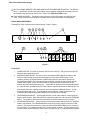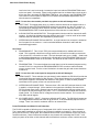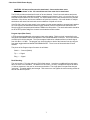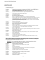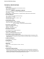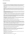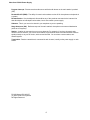
1
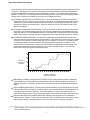
PS-232 2-CHANNEL POWER SUPPLY INSTRUCTION MANUAL 2002 Clear-Com Intercom Systems All Rights Reserved Part Number 810277 Rev. A Clear-Com Intercom Systems 4065 Hollis Street Emeryville, CA 94608-3505 U.S.A Clear-Com is a registered trademark of Clear-Com Intercom Systems. The Clear-Com Logo is a registered trademark of Clear-Com Intercom Systems. Clear-Com PS-232 Power Supply IMPORTANT SAFETY INSTRUCTIONS 1 Read these instructions. 2 Keep these instructions. 3 Heed all warnings. 4 Follow all instructions. 5 Do not use this apparatus near water. 6 Clean only with dry cloth. 7 Do not block any ventilation openings. Install in accordance with the manufacturer's instructions. 8 Do not install near any heat sources such as radiators, heat registers, stoves, or other apparatus (including amplifiers) that produce heat. 9 Do not defeat the safety purpose of the grounding-type plug. A grounding type plug has two blades and a third grounding prong. The third prong is provided for your safety. If the provided plug does not fit into your outlet, consult an electrician for replacement of the obsolete outlet. 10 Protect the power cord from being walked on or pinched, particularly at plugs, convenience receptacles, and the point where they exit from the apparatus. 11 Only use attachments/accessories specified by the manufacturer. 12 Unplug this apparatus during lightning storms or when unused for long periods of time. 13 Refer all servicing to qualified service personnel. Servicing is required when the apparatus has been damaged in any way, such as if the power-supply cord or plug is damaged, liquid had been spilled or objects have fallen into the apparatus, the apparatus has been exposed to rain or moisture, does not operate normally, or has been dropped. 14 Do not expose the apparatus to to dripping or splashing and do not place opjects filled with liquids, such as vases, on the apparatus. WARNING: To reduce the risk of electric shock, do not expose this apparatus to rain or moisture . 1 Clear-Com PS-232 Power Supply QUICK START 1 Unpack the unit and inspect for any damage that may have occurred in shipping. Connect the proper AC Mains cable to the outlet on the rear panel. 2 Install the PS-232. 3 Connect the intercom lines and Program Input as required. Connect the AC cord to the Mains circuit. 4 Set the two termination switches on the rear panel to ON. 5 Switch the Power ON. The green power light should be ON and the two red overload lights should be OFF. 6 Switch the Test Tone and A+B Link switches OFF. The yellow A+B Link light should be off. 7 Select program sends and set program levels as required using Program Trim and Program Send Level controls. 8 Set levels and sidetone nulls at remote stations. 9 The intercom system should now be operating properly. 10 Read the rest of this manual for further information. OPERATION Congratulations on choosing this Clear-Com product. The PS-232 Power Supply is a powerful, yet user friendly unit that can serve as the heart of a ClearCom system. We recommend that you read through this manual completely to better understand the functions of the PS-232 and how to optimize your system setup. Please pay particular attention to the section on system wiring, as improper wiring detracts from the performance of the system or causes system failure. If you encounter a situation or have a question that this manual does not address, contact your dealer or call Clear-Com direct at the factory. Our applications support and service people are ready to help. Description The Clear-Com PS-232 is a single rack space, one- or two-channel intercom power supply which can provide 1 amp (2 amps peak during call signals and other temporary events) at 30 Volts DC to operate Clear-Com beltpacks and remote stations. This power is supplied to either or both channels, and will support up to 40 headset stations or 15 speaker stations. Clear-Com's advanced fail-safe design can sense the difference between a short or an overload to optimally protect itself. Power is restored in as quickly as 1/2 second, depending upon whether there was a single or multiple short or overload. The other channel continues to operate normally. The PS-232's advanced fail-safe circuit will bring the power back up even under full load conditions. LED indicators signal a fault on either channel. A linelevel program input offers a master input level. Individual program selects, each with its own send level, are provided for each channel. Use of a switching power supply allows the PS-232 to operate with any AC line voltage from 90 to 240 Volts AC at 50 or 60 Hz. The unitized aluminum chassis and extrathick front panel with integral rack ears result in reduced size and a lighter weight package that maintains legendary Clear-Com ruggedness. Advanced Fail Safe Power Scheme As the heart of an intercom system, the power supply has special needs which are not met by traditional designs. It must work in adverse conditions such as low AC line voltage, momentary or continuous 2 Clear-Com PS-232 Power Supply shorts on the DC power lines to the stations, and excessive peak loads during power-on and sometimes during use. The mission of an intercom power supply is torn between giving its all to provide power in the face of these adverse conditions and protecting itself from them. This mission finds an intelligent balance in the PS-232. The following features are incorporated into the PS-232 power supply to make it quickly react to shorts and overloads yet provide a long, reliable product life: AUTOMATIC SHORT CIRCUIT PROTECTION: The microprocessor in the PS-232 checks each channel for a short or current overload 100 times per second. If a short lasting longer than 700 mS is detected, the microprocessor will shut down that channel. An short lasting less than 700 mS will not cause the PS-232 to interrupt power. However, during this 700 mS, the output current will be limited to 2 amperes. AUTOMATIC OVERLOAD PROTECTION: The PS-232 senses the difference between shorts and overloads. If an overload lasting longer than 2.5 seconds is detected, the microprocessor will shut down that channel. An overload lasting less than 2.5 seconds will not cause the PS-232 to interrupt power. During this 2.5 seconds, the output voltage will be reduced to limit the current to 2 amperes. AUTOMATIC POWER RESTORE: The PS-232 microprocessor senses the difference between short-term and long-term shorts and overload conditions. After the first few times a short or overload occurs the PS-232 will try to restore power after only 0.5 seconds. If the short or overload persists or repeatedly happens, the microprocessor will take progressively longer (to a maximum of 20 seconds) to try to restore power. This protects the PS-232 from damage due to overheating. Once the short is removed, the channel will recover, even under a full load condition. The automatic power restore times are shown in the following chart: 20 20 15 14 Number of Seconds to 10 Restore 5 0 7 4 0.5 2 0 1 2 3 4 5 6 7 8 9 10 11 12 13 14 15 16 17 18 19 20 Number of Recent Shorts or Overloads INDIVIDUAL CHANNEL SHORT CIRCUIT PROTECTION: Each individual channel is separately overload and short circuit protected and may draw as much as 2 Amps, though the total to both channels is limited to 2.25 Amps. A short on any one intercom line will not bring the whole system down.1 FRONT PANEL INDICATIONS: There are two Overload indicators on the front panel (one for each channel) and a Power indicator for the power supply. The Overload indicators light steady when an overload or short condition is detected. They blink if power to a channel has been shut off as a result of an overload or short. There is also an indicator to show when channels A and B are linked. PARALLELING MULTIPLE POWER SUPPLIES: Multiple power supplies can be paralleled to increase system capacity. The PS-232 microprocessor will automatically detect the actions of other power supplies during overloads and shorts circuits to restore power as quickly as possible. 1 Power supply lines connected together at remote stations will disable the individual channel s h o r t circuit protection feature. 3 Clear-Com PS-232 Power Supply MULTI-CHANNEL REMOTE STATIONS MAINTAIN THE POWER LINE ISOLATION: The RM-220, KB-211, and MR-202 as well as any two-channel remote stations or beltpacks are designed to use the isolated power provided by the PS-232. Refer to the INSTALLATION section. LOW NOISE CIRCUITRY: The direct current outputs of the PS-232 contain very little hum and noise. The PS-232 does not contribute to audible noise in the remote stations and beltpacks. FRONT AND REAR PANELS A description of the connectors and controls follows. Refer to Figure 1. 7 12 4 3 2 5 8 6 9 1 10 11 Figure 1 Front Panel 1 POWER SWITCH: Turns the AC power to the PS-232 on and off. The green Power light will illuminate when the power is ON. 2 OVERLOAD INDICATORS: If a short circuit or overload condition appears on either of the intercom channel outputs, the red Overload light for that channel will illuminate. If this condition persists, the microprocessor will disconnect power to that channel and the red Overload light will blink. If a red Overload light is blinking, the fault on that channel must be located and removed. When the fault is removed, the PS-232 will restore power to that channel and the Overload light will go out . If there are no shorts, but the Overload light blinks, an overload exists, possibly due to too many intercom stations connected on that intercom line. If the failure continues, unplug the intercom line connected to the affected channel. Its red Overload light should go out. This indicates a short in that line. Follow that intercom line connecting and disconnecting cables along the line until the fault is isolated. 3 PROGRAM SEND ON/OFF: These toggle switches, one for each channel, connect program audio to each channel. Both channels receive the same signal from the rear panel PROGRAM INPUT. The number of active sends will not affect the overall send level to any channel. 4 PROGRAM SEND LEVEL: These controls (one for each channel) adjust the level of program heard in that channel. The PROGRAM switch must be ON for the control to function on that channel. (The level controls work in conjunction with the PROGRAM TRIM (8) level control on the rear panel.) For a higher program level, turn the control clockwise. For less program level turn the control counter-clockwise. If the control is all the way up on a channel and the program 4 Clear-Com PS-232 Power Supply level in the line is not loud enough, increase the input level with the PROGRAM TRIM control on the rear panel. Conversely, if there is still program heard on a channel when the its level is all the way down, decrease the PROGRAM TRIM level. Any change in the PROGRAM TRIM level control on the rear panel to adjust for one channel will necessitate adjustments on the other channel to compensate. NOTE: Do not force the controls past their stop points as this will damage them. 5 TEST TONE: This toggle switch turns on a 440 Hz test tone which can be heard on either or both channels when the PROGRAM SEND switch for that channel is in the OFF position. It can be handy for identifying which intercom channel is which or for other test purposes. The PROGRAM SEND LEVEL controls adjust the level of the test tone on each channel. 6 A+B LINK SWITCH and INDICATOR: This toggle switch links the audio for channels A and B together. A yellow light indicates when the channels are linked. It can be useful to have both channels linked for rehersals, but separated for performances. 7 INTERCOM LINE CONNECTOR and SWITCH: A single intercom line connector is located on the front panel for convenience. It can be switched between channels A and B with the associated toggle switch. Rear Panel 8 PROGRAM INPUT: This 1/4 inch TRS jack accepts a balanced or unbalanced line-level signal. This is typically a feed from a mixing console, an air feed from a studio to remote site over a phone line, or an audio cue track. The input accepts levels up to +10 dBV. Send levels to the individual channels are controlled with a combination of the PROGRAM TRIM level and the PROGRAM SEND levels on the channels. This feed can be fed to either or both intercom lines. 9 PROGRAM TRIM: This control adjusts the overall input level of the external program coming into the PS-232. It is used with the PROGRAM SEND LEVEL controls to achieve desired system program levels. Turn the control clockwise to increase the gain and counter-clockwise to reduce it. NOTE: Do not force this control past its stop points as this will damage it. 10 TERM. ON/OFF: These switches (one per channel) select whether the PS-232 will provide the required 200 Ohm termination for each channel. These should always be on unless there are other power supplies or terminated main stations in the system. If there are other possible terminations in the system, all but one must be turned off. 11 INTERCOM LINE CONNECTORS: There are three 3-Pin male XLR jacks per channel, wired in parallel, or looped through. All the stations in the system are ultimately connected to the PS-232 through these jacks. Because intercom audio is bidirectional, they are neither inputs nor outputs, but may be thought of as "ports." Pin 1 is connected to the shield and carries the signal ground. Pin 2 carries the DC voltage that runs the remote stations. Pin 3 carries two way audio and call signals. 12 AC POWER SUPPLY INPUT: Connects to AC with an IEC cable. The PS-232 will accept any line voltage between 90 and 240 Volts AC @ 50-60 Hz. It will automatically adjust to the line voltage. There is no need for a selector switch or an external fuse. Power Distribution and Short Circuit Protection The PS-232 is capable of delivering up to 2 amps peak of 30 Volt DC current to Clear-Com stations. The 2 amps peak is available on channel A and 2 amps is available on channel B. Since the total capacity of the PS-232 is 2 amps peak, the combined current of both of the channels at once may not exceed this maximum. Short circuits and overloads on any channel will not damage the PS-232. It will simply cut power off to either or both channels which exceed their maximum current or which cause the 5 Clear-Com PS-232 Power Supply system maximum to be exceeded. A channels which is within its maximum current rating will not be affected by the other channel being automatically cutoff. Depending upon how many shorts or overloads a channel has experienced recently, the PS-232 will attempt to turn power on again within 500 mS to 20 seconds of automatically cutting off power to an overloaded channel. This allows momentary short or overload conditions to clear automatically. If the PS-232 cuts power off to one or both channels, it will indicate which channel is affected by blinking the red overload LEDs corresponding to these channel(s). This indication will assist in locating the shorted or overloaded channel. Shorts are generally caused by miswiring or damaged cables. Overloads are generally caused by connecting too many beltpacks and stations to a channel. The current requirements of Clear-Com remote stations and beltpacks vary with model and use. A station that is simply '"on" and idling in the circuit may draw only a small amount of current. The PS-232 15 Number of Speaker 10 Stations 5 Overload Acceptable 5 10 15 20 25 30 35 40 Number of Beltpacks will power up to 50 Beltpacks, 15 Speaker Stations, or a mix of the two. Refer to the following chart to determine how many of each can be powered in varying combinations. Contact your dealer or ClearCom if you require further assistance in determining the overall current requirements of your system. INSTALLATION Intercom Line Connection The PS-232 provides three rear panel 3-pin male XLR connectors for each intercom line. These connectors are wired in parallel and intended for loop-through connection. Any single-channel station or channel of a multi-channel station connected on a line plugged into Channel A of the PS-232 will be "party-lined" with all the other stations on that same channel. In a multi-channel system, the goal is to assign specific people to the correct group, i.e. the other people whom they need to be in contact with the most. This is particularly important when the party line users are on a single-channel beltpack or station; less so if they are on multi-channel stations. The pinout of the intercom connectors is as follows: Pin 1 --- Ground (Shield) Pin 2 --- Power (+30 VDC) Pin 3 --- Audio Line Termination (Rear Panel) Switching of the channels' terminations ON and OFF are done with the rear-panel toggle switches. In most systems, all terminations on the PS-232 should be in the ON position (default setting). The fundamental concept of Clear-Com Party-Line intercom is that all channels are terminated in one location, preferably at the power supply. 6 Clear-Com PS-232 Power Supply CAUTION: All intercom lines must be terminated. Care must be taken not to '"double-terminate" a line. All unused intercom lines must also be terminated. The PS-232 provides terminations for each of its two channels. Clear-Com main stations and power supplies provide switch-selectable termination networks on all intercom lines. It is up to the user to insure that the terminations are set correctly. An unterminated line will cause excessive levels, possible oscillation of line drivers, and severe unbalance of hybrid null networks. A line with double or multiple terminations will cause low levels and severe unbalance of hybrid null circuits. If the PS-232 is the only power supply in the system (no other power supplies or powered main stations are in the system) the termination switch on each channel of the PS-232 should be switched to ON. Simply toggle the rear-panel switch labeled TERM to the ON position. The termination switch should be set to the OFF position only if the channel is terminated at another station. Program Input (Rear Panel) A TRS connector provides the main program input to the station. This input level is controlled by the rear panel PROGRAM TRIM control adjacent to the PROGRAM INPUT connector. This control sets the overall level for all the channels. The input accepts a balanced or unbalanced line-level audio signal from -20 dBv to +10 dBv. The program can be fed to either or both of the intercom lines by using the front panel toggle switches labeled PROGRAM ON/OFF. There is one of these switches for each channel. The pinout of the Program Input Connector is as follows: Shield --- Ground (Shield) Tip --- + Signal Ring --- - Signal Rack Mounting The unit requires 1.75 inches (44 mm) (1RU) of rack space. It requires no additional free rack space above or below it for ventilation. The station is 5.25 inches (133 mm) in depth and requires at least 2 1/2 inches clearance in the rear for connectors and cables. The single-piece front panel has integral "rack ears". This adds stability and strength. Take care not to over tighten the rack mounting screws as this can mar the front panel. 7 Clear-Com PS-232 Power Supply System Checkout Before you turn on the power: Check Termination There should be one and only one termination for each channel in the system. This termination is usually set to ON at the main station or power supply. To ascertain that only one termination is present on the channel, perform the following test: 1 Using a multimeter, measure the resistance between pins 1 and 3 on one of the Channel A XLR connectors at the rear of the unit. 2 If the channel is terminated properly, then the resistance should measure approximately 4,000 Ohms. A very high channel resistance means the channel is not terminated. Channel resistance of 2,000 Ohms indicates a double-termination. If a double-termination is indicated, Locate the other power supply or mainstation and set its termination to OFF. NOTE: The location of the termination switch varies with model. On some products, the termination switches are on the rear panel; on others they are inside the unit. Consult the unit's manual for the location. 1 Repeat for the other channels. 2 Check resistance between Chassis Ground and pin 1. Using an Ohmmeter, measure the resistance from pin 1 on the main station or power supply to chassis ground. The measurement should read 10 Ohms. A high reading (over 100 Ohms) indicates that the 10 Ohm resistor in the unit has failed and requires replacement. Failure to perform the replacement will result in an audible "buzz" in the system. A reading of less than 10 Ohms (or a short) typically indicates that the shell and pin 1 of one of the interconnect cables are shorted together. Test the individual cables until the culprit is located and repair or replace the cable. NOTE: PIN 1 and the shell of the XLR plug on the interconnect cables should NOT be connected together. Check Intercom Cable Resistance For minimal crosstalk, the ground resistance of the intercom cables should be as low as possible, preferably less than 2 Ohms. Disconnect an intercom line from the main station or power supply. At the point in the intercom line furthest from the unit, connect a clip lead jumper between pins 1 and 2. Back at the "powered" end, use an Ohmmeter to measure the resistance between pins 1 and 2. A value of less than 4 Ohms is ideal. Final Tests After you turn the power ON: 1 Check for proper voltage on pin 2 of any intercom line or jack in a channel. It should read 26-30 Volts. 2 Test for proper operation of Call Signaling. Activate the CALL SIGNAL on any belt pack or station. The call lights on all other stations on that channel should illuminate and then go out when the call button is released. 3 Adjust the sidetone null on all stations. (Refer to the manual for each specific unit for instructions.) 8 Clear-Com PS-232 Power Supply MAINTENANCE Troubleshooting Tips Problem: Cause 1: Solution 1: System does not operate. No power to the PS-232. Green POWER light is not illuminated and no OVERLOAD lights are illuminated No AC power to the PS-232. Check AC connection and cable. Plug into dependable AC source. Cause 2: Solution 2: PS-232 has an internal power supply failure. Unit requires servicing. Problem: Cause 1: Solution 1: Red Overload Light illuminated Short or overload on that channel due to a shorted or miswired cable. Remove cables, one at a time from system until the faulty line is located. Check for shorts between pins 1 and 2. Once the short is removed, the PS-232 will reset automatically and the power will come back up within several seconds, depending upon how long the short has been present. Cause 2: Solution 2: Defective remote station. Check remote station and replace if necessary. Problem: Cause 1: Solution 1: Both red Overload Lights are illuminated System is overloaded. Remove cables, one at a time from system to help determine where the excess current requirements lie. Re-evaluate system current needs. Cause 2: Solution 2: Short in multipair cable. Remove cables, one at a time from system until the faulty line is located. Check for shorts between pins 1 and 2. Problem: Cause 1: Hum or buzz in system Inductive pickup caused by close proximity of main or remote stations to power lines or transformers. Relocate offending unit. Solution 1: Cause 2: Solution 2: 10 Ohm chassis ground resistor is open. Check the DC resistance for 10 Ohms between the chassis and Pin 1 of any intercom connector. If this condition happens, it is because the system ground came into contact with something that was "HOT" with respect to the power supply earth ground. If this occurs, carefully check the system ground and AC distribution in the area. WARNING: This is a potentially dangerous situation. A shock hazard may exist between the metal boom of a remote station headset and ground. Problem: Cause 1: Solution 1: System feedback (Acoustical) Volume control at the remote station is set too high. Adjust. Cause 2: Solution 2: Channel unterminated. Set the PS-232 temination switch for that channel to the ON position. Cause 3: Solution 3: A headset extension cord was used. Headset extension cords are not recommended. Problem: Cause 1: Solution 1: 440 Hz tone is present on either or both channels Test tone feature is on. Set the test tone switch to the OFF positon. Problem: Excessive crosstalk 9 Clear-Com PS-232 Power Supply Cause 1: Solution 1: High DC resistance in ground return. Use heavier cable; add additional conductor(s) to ground return. Cause 2: Solution 2: MULTI-CHANNEL cable pairs are not individually shielded. Replace cable with individually shield pairs. Cause 3: Solution 3: Headset cables are not wired properly or shielded properly. Correct wiring. Use headsets with properly shielded wiring. Problem: Cause: Solution: Program signal sounds distorted. Overload of PROGRAM IN circuit. Reduce PROGRAM IN level or reduce the gain of the program signal at the source, such as an audio mixer. PS-232 Block Diagram The following is a block diagram of the PS-232: 90 - 240 VAC Switching Power Supply Module Voltage Regulator Channel A Power Controller Channel A Current Sensor Channel B Power Controller Channel A Voltage Sensor Overload Overload Channel Channel A B Channel B Current Sensor Channel A Channel B Voltage Sensor Microprocessor Power Test Tone On / Off Program Trim Program Input 440 Hz Send Levels A Channel B Filter B A B Program On / Off 10 Ch A Term Ch B Term A+B Link Clear-Com PS-232 Power Supply Parts List Part Description .01 uF Ceramic Disc .1 uF Monolithic 10 uF Aluminum 470 uF Aluminum 1000 uF Aluminum 1 uF Tantalum .47 uF Aluminum NP 47 pF Ceramic Disc SMD 470 pF Ceramic Disc SMD .01 uF Ceramic Disc SMD .1 uF Ceramic Disc SMD .22 uF Ceramic Disc SMD .33 uF Ceramic Disc SMD .47 uF Tantalum SMD 22 uF Aluminum SMD LED GREEN, ROUND LED LED RED, ROUND LED LED YELLOW, ROUND LED 10 OHM 1/4W Carbon Film 1K OHM 1/2W Carbon Film .18 OHM 1W Carbon Comp .11 OHM 1W Carbon Comp 0 OHM 1/10 10.0 OHM 1/10 221 OHM 1/10 475 OHM 1/10 1.00K OHM 1/10 3.92K OHM 1/10 4.32K OHM 1/10 4.75K OHM 1/10 10.0K OHM 1/10 20.0K OHM 1/10 47.5K OHM 1/10 100K OHM 1/10 Rating 1.4KV 50V 50V 25V 35V 35V 50V 50V 50V 50V 50V 50V 25V 35V 50V SMD SMD SMD SMD SMD SMD SMD SMD SMD Part # 20% 150029 10% 150035 150064 150089 150092 20% 150116 150151 5% 151120 5% 151132 10% 151160 10% 151172 10% 151176 10% 151178 10% 151184 20% 151200 390051 480064 480065 5% 410002 5% 410121 5% 410200 5% 410201 1% 411100 1% 411197 1% 411326 1% 411358 1% 411389 1% 411446 1% 411450 1% 411454 1% 411485 SMD SMD SMD 1% 1% 1% 411514 411550 411581 Relay SPDT 24V MINI PC RELAY ITT#SZ24 450004 Pot 10K TRIMPOT PIHER#PT110WH-10K 470058 Pot 50K TRIMPOT PIHER#PT10WH-50K470059 Diode 1N5401 RECT 3A 100PIV 480005 IC 7805T POS 5V REGULATOR TO220 PKG 480083 Diode 1N5822 SHTKY 3A 40PIV 480100 IC LM833N DUAL 8 PIN DIP 480175 TransistorTIP35C NPN 100V 25A TO-218 480228 Diode BAV70 DUAL DIODE COM CATH SMD 481019 IC 833 DUAL OPAMP... SMD 481023 Transistor2222A NPN 40V 600MA... SMD 481026 Transistor2907A PNP 60V 600MA... SMD 481027 Diode BAV99 DUAL DIODE... SMD 481033 IC 74HC165 CMOS 8-BIT PAR S/R... SMD 481037 Transistor5551 NPN 150V 200MA... SMD 481068 Sw SPDT 2POS RT ANG PC MTG 510094 Sw DPDT R/A SLIDE SWITCH 510121 IC PS-232 FIRMWARE ASSEMBLY 710567 11 Designator C4 C1 C6 C28 C29 C7 C8 C2 C12 C3 C21 C26 C19 C20 C24 C10 C9 C15 C11 C17 C18 C14 C5 C13 C22 C23 C25 C16 D3 D7 D6 D8 R4 R11 R12 R13 R14 R1 R6 R5 R40 R39 R2 R52 R53 R10 R34 R35 R36 R8 R9 R22 R21 R45 R55 R3 R7 R56 R57 R19 R20 R23 R24 R25 R26 R27 R28 R29 R37 R51 R42 R41 R15 R16 R17 R18 R30 R31 R32 R33 R38 R43 R46 R47 R48 R50 K1 R54 R44 R49 D1 D2 IC1 D4 D5 IC4 Q3 Q4 D9 IC4 Q7 Q8 Q9 Q11 Q2 Q1 D10 IC3 Q5 Q6 Q10 Q12 S6 S3 S1 S2 S4 S5 S7 IC2 Component Layout Drawing 1 2 3 2899 REV ECO# A R34 475 Ch. A Fault (red) J1 +5V D6 R29 10.0K +5V 1 2 3 4 5 6 P5 R2 10 C2 1000uF C5 .33uF RB0 RB1 RB2 RB3 RB4 RB5 A DESCRIPTION DATE 1-11-02 Bias R48 100K C24 47pF BY JKG 7 9 R43 100K D9 BAV70 + - SER A B C D E F G H 1 .1uF C18 R42 47.5K 2 IC3 74HC165 CLK INH SH/LD 3 2 15 1 10 11 12 13 14 3 4 5 6 + 6 5 R49 50K .1uF C17 + - 7 Bias R31 100K IC4B LM833 R47 100K C20 47pF R41 47.5K R30 100K R23 10.0K 2 Bias Q1 MMBT2907A Q9 MMBT2222A 1 R19 10.0K R10 475 D3 Power (green) +5V +5V R51 20.0K C16 22uF GND C6 .1uF VCC +5V P8 1 2 3 4 5 R38 100K +30V 1 .22uF C14 Options 1. ALL RESISTORS ARE 1/10W 1% LISTED IN OHMS 2. RESISTORS 1/4W AND GREATER ARE 5% TOLERANCE 3. ALL CAPACITORS ARE LISTED IN MICROFARADS B 3 R13 1K 1/2W R11 1K 1/2W R37 10.0K R27 10.0K R33 100K C25 .47uF C13 .33uF R32 100K R24 10.0K C9 470 pF C7 470uF + R5 .11 1W R8 1.00K R3 4.75K R1 .18 1W NOTES: (UNLESS OTHERWISE SPECIFIED) Bias IC4A CW LM833 SOIC QH QH 7805T VOut CHK R50 100K 3 C23 .33uF C19 47pF R39 10 1 3 1 R46 100K +30V Ch. B Fault (red) 10 9 8 7 6 5 IC2 PIC16C505P RC0 RC1 RC2 RC3 RC4 RC5 VIn IC1 2 C22 .33uF R35 475 D7 +5V 13 12 11 4 3 2 C11 .1uF +5V 1 2 Release to Manufacturing Balanced Program Input R4 10 1/4W + PROGRAMMING / TEST INTERFACE 1 - Gnd / Gnd 2 - Data / Strobe 3 - n/a / Data Out 4 - Clock / Clock 5 - MCLR (not) / Data In 6 - +5V / n/a C4 .01uF 1.4KV C1 .1uF GND 2 4 +30V R40 0 3 1 +5V D4 1N5822 S3 C27 .22uF 3 1 S6 CW R54 10K Ch. B 2 Program Off / Test Tone CW R44 10K Ch. A 2 C15 .01uF 6 4 3 1 Tone Off Tone On Q7 MMBT2222A 1 R15 100K D1 1N5401 Program On Q10 MMBT5551 Q5 MMBT5551 2 Q3 TIP35C 2 3 1 +30V 3 2 +30V 3 2 1 3 2 C 5 2 R45 4.32K R55 4.32K Ch. B Program Level 2 Ch. A Program Level 2 S1 R21 3.92K R17 100K +5V C26 .47uF NP C21 .47uF NP R25 10.0K Q11 MMBT2222A 1 R20 10.0K Q2 MMBT2907A R26 10.0K R28 10.0K 5 2 Link Off +30V 3 S2 6 4 3 1 1 D 1 R36 475 D8 D10 BAV99 K1 3 4 SCALE SHEET: + C12 1uF TANT + C3 1uF TANT SIZE 3-13-01 C29 10uF 710568SA.DSN 1 OF: 1 ----------------------- ORCAD P/N DATE DATE + R53 221 S5 APP C28 10uF R57 4.75K Ch. B Termination 2 5 1 R22 3.92K R18 100K DATE JKG + R52 221 S4 2 +30V Q8 MMBT2222A 1 R16 100K D2 1N5401 3 CHK DWN R56 4.75K +5V D5 1N5822 +30V Ch. A Termination +5V Q12 MMBT5551 Q6 MMBT5551 2 Q4 TIP35C 2 3 Link (yellow) R14 1K 1/2W R12 1K 1/2W C10 470 pF C8 470uF + Link On R9 1.00K R6 R7 .11 1W 4.75K 1 3 2 1 1 2 3 1 VDD VSS 14 3 2 D 6 C 1 B 3 4 5 3 2 3 2 P1 3 8 4 6 30 VDC Input from Switching Power Supply 3 1 4 5 A + 3 1 3 1 1 2 C DWG No. TITLE: CH B 1 3 4 6 CH A 1 1 1 P10 1 INTERCOM SYSTEMS P9 P7 P6 1 1 1 E 710568 - SCH - C - REV A CLEAR-COM R 2 P4 P3 P2 Schematic PS-232 Power Supply 2 2 2 S7 2 5 Test Jack 2 2 2 E 4 3 4 3 4 3 4 3 4 3 4 3 4 3 1 2 3 4 Clear-Com PS-232 Power Supply CLEAR-COM LIMITED WARRANTY Clear-Com products are warranted to be free from defects in materials and workmanship for a period of one year from the date of sale. This warranty does not cover any defect, malfunction or failure caused beyond the control of ClearCom, including unreasonable or negligent operation, abuse, accident, failure to follow instructions in the manual, defective or improper associated equipment, attempts at modification and repair not authorized by Clear-Com, and shipping damage. Products with their serial numbers removed or defaced are not covered by this warranty. This warranty is the sole and exclusive express warranty given with respect to Clear-Com products. It is the responsibility of the user to determine before purchase that this product is suitable for the user's intended purpose. Any and all implied warranties, including the implied warranty of merchantability are limited to the duration of this express limited warranty. Neither Clear-Com nor the dealer who sells Clear-Com products is liable for incidental or consequential damages of any kind. For your own records fill in the information below: * Model No.________________________________ * Serial No.______________________ Date Purchased_____________________________ Purchased from (dealer)______________________________________________________ Address___________________________________________________________________ City_________________________________State___________________Zip____________ Factory Service All equipment returned for repair must be accompanied by documentation stating your return address, telephone number and date of purchase, along with a description of the problem. Note: Do not return any equipment to the factory without first obtaining a Return Authorization Number. After obtaining a return authorization, send equipment to be repaired to: Customer Service Department Clear-Com Intercom Systems 4065 Hollis Street Emeryville, California 94608-3505 Telephone: (510) 496-6666 Telefax: (510) 496-6601 Warranty Repairs - If in warranty, no charge will be made for the repairs. Equipment being returned for warranty repair must be sent prepaid and will be returned prepaid. Non-Warranty Repair - Equipment that is not under warranty must be sent prepaid to Clear-Com. If requested, an estimate of repair costs will be issued prior to service. Once your approval for repair, and repair of equipment is completed, the equipment will be shipped freight collect from the factory to the customer. 14 Clear-Com PS-232 Power Supply TECHNICAL SPECIFICATIONS POWER SUPPLY Type: Switching, with post filters and overload reset circuitry Output Voltage: 30 volts DC Output Current: Channel A, 1 amp continuous, 2 amps max Channel B, 1 amp continuous, 2 amps max Short Circuit Reset Time: 0.5 to 20 sec. depending upon recent overload activity Hum & Noise: < -70 dBV Station Capacity: 40 headset stations or 15 speaker stations, distributed over both channels PROGRAM AMPLIFIER Type: Transformerless, Balanced Differential Input Input impedance: > 100 kΩ Frequency Response: 150 Hz - 18 kHz ± 2 dB Line Level Input: -20 dBV SYSTEM SPECIFICATIONS Termination Impedance: 200 Ω , switchable Intercom Line Length: 5,000 ft. maximum (single channel) 500 ft. for crosstalk < -50 dB (with multi-channel stations) REAR PANEL CONNECTORS Intercom: (6) XLR-3M (3 per channel) Program: (1) 1/4" TRS AC Power: (1) IEC 320 connector REAR PANEL CONTROLS (2) Termination on/off; (1) program input level FRONT PANEL CONNECTOR Intercom: (1) XLR-3M (selectable channel A or B) FRONT PANEL CONTROLS & INDICATORS (1) Intercom Select switch; (2) Program On-Off switches; (2) Program Send Level controls; (1) Test Tone switch; (1) A+B Link switch; (1) Power On switch; (2) "Overload" lights; (1) "A+B Link light; (1) Power "On" light POWER REQUIREMENTS 90 - 240 VAC, 50 - 60 Hz, 60 VA ENVIRONMENTAL 32 - 122o F (0 - 50o C) DIMENSIONS 19" W x 1.75" H x 5.25" D (483 mm x 44 mm x 133 mm) WEIGHT 4.5 lbs. (2.05 kg) NOTICE ABOUT SPECIFICATIONS While Clear-Com makes every attempt to maintain the accuracy of the information contained in its product manuals, that information is subject to change without notice. Performance specifications included in this manual are design-center specifications and are included for customer guidance and to facilitate system installation. Actual operating performance may vary. 15 Clear-Com PS-232 Power Supply GLOSSARY Some of the terms used when discussing critical communications for television or theatre may be new to you as they are unique to intercom applications. Although many of the terms are common to other audio applications, to be certain you understand their meanings we offer the following definitions: All Call: Ability to push one button from the main station and talk to all channels at once on a multiple channel system. Ambient Noise: Those background sounds which are not part of the specific communication but are picked up by the microphone. Selection of a good "noise-cancelling" mic will reduce ambient noise. Beltpack: A portable electronics package worn on the belt or mounted on a wall or other convenient location. Interconnects to system with mic cable and is powered by a central power supply or main station. Bridging, High Impedance (hi-Z): A method of connecting to an audio line (such as Clear-Com) without loading or taking appreciable power from that line. Simply stated, as you add more and more stations to the line, the volume remains constant. Call Signaling: This feature is included with the majority of Clear-Com products. It is a visual indicator on a station (lamp or LED) used to attract the attention of an operator who has removed the headset. Channel: A channel is the line that connects parties together within a party line - it is a two-way talk path. For example, if you have six people who need to hear one director, you have a seven-station single-channel need. If the same director needs to speak privately to any one of the six, add a second channel. You now have a seven-station, two-channel system. Closed-Circuit: Any intercom which is connected via cable (also called hard-wired). The other type would be Wireless. . .we make those too. However, if you want privacy and versatility, you probably want a closed-circuit system or a combination of both. Cross Talk: Leakage of audio transmissions from one channel to another. Dry Pair: A telephone term is used to describe a pair of wires (2 conductors) that carry audio but no DC voltage. Contrast this with a "Wet Pair" that carries both audio and voltage. Duplex: Duplex refers to bidirectional communications. Normal communication between individual talking face to face is "full duplex" - in other words you can talk and listen simultaneously. The other alternative is "half-duplex" such as a push-to-talk situation where one station at a time can talk while others listen. A walkie-talkie is a good example of half-duplex communication. IFB: The term means "Interrupted Fold Back." A Fold-Back is a monitor system that allows, for example, talent to hear their voices or musicians to hear their voices and instruments on stage. IFB (program interrupt) disconnects the program audio source while the talk button on the main station is pushed. ISO: A private conversation path. An ISO channel allows one to simply push a button and transfer themselves and the person they wish to speak with to an isolated channel. Linking: Linking ties separate channels into one single party line. Main Station: This is a product that includes both the ability to communicate with multiple channels without connecting them together, and to power all the stations connected to these channels. Master Station: A remote station which needs AC power to operate Multi-Channel: More than one channel Party Line (P.L.): Intercom system where all people talking on the system can talk or listen to each other simultaneously. Also called conferencing. Point to Point: One path to one person. Program: Audio source that is fed into the intercom channels. 16 Clear-Com PS-232 Power Supply Program Interrupt: Disconnects the audio source while the talk button on the main station is pushed. (IFB) Remote Mic Kill (RMK): The ability for certain main stations to shut off all microphones on beltpacks in a system. Remote Station: Like the beltpack, this would be any of the products connected to the intercom line that allow duplex or half-duplex conversation, but do not contain a power supply. Sidetone: This is your own voice heard in your earphone as you are speaking. Stage Announce (SA): Redirects output of the main station's microphone to an external destination (such as a PA system). Station: A station is connected to one or more channels. For example, if you have six people who need to hear one director, you have a seven-station single-channel need. If the same director needs to speak privately to any one of the six, add a second channel. You now have a seven-station, twochannel system. Termination: Passive network that is connected in each channel, usually on the power supply or main station. PS-232 Manual P/N 810277 (C) 2002 Clear-Com Systems All Rights Reserved 17