1
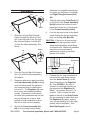
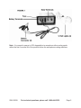
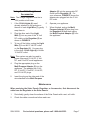
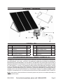
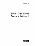
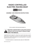
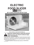
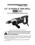
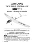
45 WATT SOLAR KIT
90599
Set up and Operating Instructions
Visit our website at: http://www.harborfreight.com
Read this material before using this product.
Failure to do so can result in serious injury.
Save this manual.
Copyright© 2003 by Harbor Freight Tools®. All rights reserved. No portion of this manual or any artwork
contained herein may be reproduced in any shape or form without the express written consent of
Harbor Freight Tools. Diagrams within this manual may not be drawn proportionally. Due to continuing
improvements, actual product may differ slightly from the product described herein. Tools required for
assembly and service may not be included.
For technical questions or replacement parts, please call 1-800-444-3353.
Revised Manual 09j
Specifications
Panel Dimensions 12-1/4” W x 36-1/2” L x 7/8” T
15 W per panel, 14.5 V
Output
(working)
23.5 OCV (Open Circuit Volts)
Adapter Outlets
3, 6, 9, and 12 VDC
Weight
9.7 lb.
4.
Store idle equipment. When not in
use, products must be stored in a dry
location to inhibit rust. Always lock
up products and keep out of reach of
children.
5.
Use the right product for the job.
Do not attempt to force a small
product to do the work of a larger
industrial product. There are certain
applications for which this product
was designed. It will do the job better
and more safely at the rate for which
it was intended. Do not modify this
product and do not use this product
for a purpose for which it was not
intended.
6.
Dress properly. Do not wear loose
clothing or jewelry as they can be
caught in parts during installation.
Protective, electrically nonconductive
clothes and nonskid footwear are
recommended when working. Wear
restrictive hair covering to contain
long hair.
7.
Use eye protection. Always wear
ANSI-approved impact safety goggles
during assembly and when working
with tools and equipment.
8.
Do not overreach. Keep proper
footing and balance at all times. Do
not reach over or across wires or
cables.
9.
Maintain products with care. Keep
products clean for better and safer
performance. Follow instructions
for changing accessories. Inspect
product cords periodically, and if
damaged, have them repaired by an
authorized technician. The panels
must be kept clean, and free from oil
and grease at all times.
Save This Manual
You will need the manual for
the safety warnings and precautions,
assembly instructions, operating and
maintenance procedures, parts list and
diagram. Keep your invoice with this
manual. Write the invoice number on the
inside of the front cover. Keep the manual
and invoice in a safe and dry place for
future reference.
Safety Warnings and
Precautions
WARNING: When using product, basic
safety precautions should always
be followed to reduce the risk of
personal injury and damage to
equipment.
Read all instructions before using this
product!
1.
Keep work area clean. Cluttered
areas invite injuries.
2.
Observe work area conditions. Do
not use the Regulator in damp or wet
locations. Don’t expose Regulator
to rain. Do not use electrically
powered products in the presence of
flammable gases or liquids.
3.
Keep children away. Children must
never be allowed in the work area.
Do not let them handle product,
accessories, or cords.
REV 08i
SKU 90599
For technical questions, please call 1-800-444-3353.
Page 2
10. Disconnect power. Unplug from
accessories or batteries when not in
use and disconnect the Solar Panels
from the Regulator at night.
11. Stay alert. Watch what you are
doing, use common sense. Do not
operate any product when you are
tired.
12. Check for damaged parts. Before
using any product, any part that
appears damaged should be
carefully checked to determine that
it will operate properly and perform
its intended function. Check for
alignment and binding of parts; any
broken parts or mounting fixtures;
and any other condition that may
affect proper operation. Any part
that is damaged should be properly
repaired or replaced by a qualified
technician. Do not use the product if
any switch does not turn On and Off
properly.
13. Guard against electric shock.
Prevent body contact with grounded
surfaces such as pipes, radiators,
ranges, and refrigerator enclosures.
is any doubt, do not operate the
product.
16. Maintenance. For your safety,
service and maintenance should be
performed regularly by a qualified
technician.
17. The warnings, cautions, and
instructions discussed in this
instruction manual cannot cover all
possible conditions and situations
that may occur. It must be understood
by the operator that common sense
and caution are factors which cannot
be built into this product, but must be
supplied by the operator.
Unpacking
When unpacking, check to make
sure the parts listed on at the end of this
manual are included. If any parts are
missing or broken, please call Harbor
Freight Tools at 1-800-444-3353 as soon
as possible.
14. Replacement parts and
accessories. When servicing, use
only identical replacement parts.
Use of any other parts will void the
warranty. Only use accessories
intended for use with this tool.
Approved accessories are available
from Harbor Freight Tools.
15. Do not operate product if under
the influence of alcohol or drugs.
Read warning labels if taking
prescription medicine to determine
if your judgment or reflexes are
impaired while taking drugs. If there
SKU 90599
For technical questions, please call 1-800-444-3353.
Page 3
hardware (not supplied) through the
four holes on the bottom of the Left
and Right Triangle Frames (6a &
6b).
Assembly
6a
5.
Carefully place each Solar Panel (1)
on the front of the Frame Assembly
(6a-6d) so that the bottom of each
panel fits into the slot on the bottom
of the Frame Assembly (6a-6d).
6.
Lock the two eye hooks on the backcenter frame into the two protruding
bolts on the Top Link Bar (6d).
Slot 3
6b
1.
Slide the Left and Right Triangle
Frame (6a and 6b) into slot 1 and
slot 3 on both ends of the Top Link
Bar (6d) and Bottom Link Bar (6C)
(to form the frame assembly). See
above.
6c
Slot 2
CAUTION: If the unit is to be mounted
on a rooftop, be especially careful
when climbing ladders and walking
on sloped roofs. Additional hardware
may have to be purchased if
permanently mounting the Solar
panels on a rooftop.
Hook-Up Diagram
6d
Regulator (2)
Slot 1
Solar Panels (1)
lead
wires
2.
Push the Top Link Bar (6d) down to
slot 2 (to lock the frame assembly).
See above.
3.
Determine where you want to position
the Frame Assembly (6a-6d) making
sure it is facing south (for maximum
sun exposure) with no obstructions
in front of it. The Regulator (2) must
be in a dry, well ventilated location
nearby. If necessary, build a small
structure that guarantees the unit will
stay dry during rain or snow, and,
provide enough ventilation to allow
the unit to vent and cool properly.
4.
Secure the Frame Assembly (6a6d) to its mounting location using
SKU 90599
7.
Connect the two ring connectors at
the end of the lead wires coming
from the Solar Panels (1) to the
Solar Terminals on the Regulator
(2). See FIGURE 1. Be sure to
connect by matching polarities on
the wires and the Regulator (2).
Black (-) is negative and red (+) is
positive. Then, connect the wire
leads so that all of the Solar Panels
(1) are connected to each other and
the Regulator (2) (again, making
sure you are hooking up to the right
polarity on the Regulator). See
Hook-Up Diagram, above.
For technical questions, please call 1-800-444-3353.
Page 4
Note: It is normal to see up to 20% degradation in amorphous silicon solar panels
within the first 6 months life of the product before the amorphous coating stabilizes.
SKU 90599
For technical questions, please call 1-800-444-3353.
Page 5
Operation
stop charging the battery, disconnect
the solar panels from the charge
regulator. Note: The charge regulator
provides “over charge” protection. If
the battery voltage is higher than 14.5
V, the regulator will shut off charge
from solar panel.
Note: Performance of the Solar Panels
will vary dependent on site location,
angle of the panels in relation to the
arc of the sun, and available sunlight.
Recharging a Battery
1.
To recharge a 12 volt battery
(not included), paying attention
to the proper polarity (black (-) is
negative and red (+) is positive),
connect the two ring terminals on
the Battery Connector (3) to the
Battery Terminals on the back of
the Regulator (2). See FIGURE
1. Then, connect the black clamp to
the black or negative (-) terminal on
the battery (not included). Finally,
connect the red clamp to the red or
positive (+) terminal on the battery.
Always avoid accidental contact of
the red and black battery clamps to
each other.
Note: Do not change the order explained
in number 1 above or electric shock
resulting in serious injury or death
may occur.
2.
Turn on the Regulator. See the On/
Off switch in FIGURE 2 on page 5.
3.
Never leave the battery (not included)
unattended while charging. When
the battery (not included) is fully
charged, the reading on the voltage
display will show “13” or above.
Note: the voltage display will have to
be turned on in order to monitor the
batter voltage. (It is recommended to
leave the voltage display off when not
monitoring the battery voltage since it
consumes energy.) Twelve (12) Volt
batteries should charge to 13 Volts
for a full charge. If the intent is to
SKU 90599
4.
The Regulator (2) provides the
following protection while charging:
a.Over-discharge Protection: When
the electricity level of the battery
(not included) goes too low (below
11 volts) the Regulator (2) will
automatically shut off the power
output to prevent damage to the
battery (not included). If this occurs,
stop using the battery (not included)
and charge it until the Voltage
display shows 13 volts.
b.Overcharge Protection: If the
electricity level on the battery (not
included) goes too high (above
14.5 volts) the Regulator (2) will
automatically shut off power input to
prevent damage to the battery (not
included).
c. Overload Protection: If the output
current exceeds 4 amps the fuse
(See FIGURE 1) will blow to prevent
damage to the controller in the
Regulator (2). If this occurs, have
an authorized service technician
replace the fuse.
Note: The On/Off switch of the charge
regulator must be in the “On”
position to activate the three
protection functions mentioned
above.
For technical questions, please call 1-800-444-3353.
Page 6
Adapter (5) into the appropriate DC
Outlet on the Regulator (2). For
your reference, FIGURE 2 shows the
adapter wire plugged into the 3 Volt
DC outlet.
Using the 12 Volt Lights and
Accessories.
Note: The Charge Regulator must be in
“ON” position at all times.
1.
If the 12 Volt Lights (4) aren’t
already attached to the sockets on
the end of each Light Wire (7), gently
snap them in.
2.
Plug the other end of the Light
Wire (7) into any one of the 12 Volt
DC outlets on the Regulator (2) as
shown in FIGURE 2.
3.
To turn off the lights, unplug the Light
Wire (7) from the 12 Volt DC outlet
on the Regulator (2). You may plug
in the other 12 Volt Light (4) to either
12 Volt DC outlet.
6.
Operate your appliance.
7.
When finished, unplug the Multi
Purpose Adapter (5) wire plug from
the Regulator (2) and then unplug
the Multi Purpose Adapter (5) from
the appliance.
Note: This system can also be used to
power other small 3 Volt DC, 6 Volt
DC, and 9 Volt DC small appliances.
4.
Plug the appropriate plug on the
Multi Purpose Adapter (5) into the
appliance. The adapter has 3 Volt
DC, 5 Volt DC, 6 Volt DC, 9 Volt DC,
and 12 Volt DC plugs.
5.
Insert the plug on the other end of the
wire attached to the Multi Purpose
Maintenance
When servicing the Solar Panels, Regulator, or Accessories, first disconnect the
cable from the Regulator to the Solar Panels.
1.
Periodically, gently clean the surface of the Solar Panels with a wet, soft cloth.
2.
Check the cable connections before each use.
SKU 90599
For technical questions, please call 1-800-444-3353.
Page 7
Assembly Drawing
Parts List
Part
Description
Q’ty
Part
Description
Q’ty
1
Solar Panel
3
6a
Left Triangle Frame
1
2
Regulator
1
6b
Right Triangle Frame
1
3
Battery Connector
1
6c
Bottom Link Bar
1
4
12 Volt Light
2
6d
Top Link Bar
1
5
Multi-purpose Adapter
1
7
Light Wire
2
PLEASE READ THE FOLLOWING CAREFULLY
THE MANUFACTURER AND/OR DISTRIBUTOR HAS PROVIDED THE PARTS DIAGRAM IN THIS MANUAL
AS A REFERENCE TOOL ONLY. NEITHER THE MANUFACTURER NOR DISTRIBUTOR MAKES ANY
REPRESENTATION OR WARRANTY OF ANY KIND TO THE BUYER THAT HE OR SHE IS QUALIFIED TO
MAKE ANY REPAIRS TO THE PRODUCT OR THAT HE OR SHE IS QUALIFIED TO REPLACE ANY PARTS
OF THE PRODUCT. IN FACT, THE MANUFACTURER AND/OR DISTRIBUTOR EXPRESSLY STATES
THAT ALL REPAIRS AND PARTS REPLACEMENTS SHOULD BE UNDERTAKEN BY CERTIFIED AND
LICENSED TECHNICIANS AND NOT BY THE BUYER. THE BUYER ASSUMES ALL RISK AND LIABILITY
ARISING OUT OF HIS OR HER REPAIRS TO THE ORIGINAL PRODUCT OR REPLACEMENT PARTS
THERETO, OR ARISING OUT OF HIS OR HER INSTALLATION OF REPLACEMENT PARTS THERETO.
NOTE: Some parts are listed and shown for illustration purposes only and are not available individually as
replacement parts.
SKU 90599
For technical questions, please call 1-800-444-3353.
Page 8