1
V1.7 Supplementary Manual
This supplementary manual explains mainly the functions that have been added or changed in
CL5/CL3/CL1 firmware V1.6 and V1.7.
Use it in conjunction with the CL5/CL3/CL1 Owner’s Manual and Reference Manual.
EN
Contents
Contents
User settings............................................................................ 15
Added functions for the GAIN/PAN/ASSIGN knobs (assignable encoders)...............
Added custom fader bank functions .......................................................................
Added load/save functions .....................................................................................
Added function for recovering from USB overcurrent..............................................
SELECTED CHANNEL section ...................................................... 3
Improved gain indication......................................................................................... 3
Improved HPF indication ......................................................................................... 4
15
15
18
21
Other functions ....................................................................... 22
Improvements to the channel name display ........................................................... 22
Added channel color .............................................................................................. 22
Added GPI functions............................................................................................... 23
Initializing the Dante audio network settings .......................................................... 23
Block Diagram ........................................................................................................ 24
Centralogic section ................................................................... 4
Improved DCA group indication .............................................................................. 4
Input channels .......................................................................... 5
Additional head amp setting functions when changing the input patching.............. 5
Grouping and linking ............................................................... 7
Improved display of DCA group / MUTE group names............................................. 7
Added functions for DCA groups ............................................................................. 8
Improvements in channel link display ...................................................................... 9
Monitor and Cue ..................................................................... 10
Extended cue functions ......................................................................................... 10
Meters ..................................................................................... 10
Added functions for meter display ......................................................................... 10
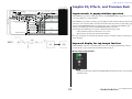
Graphic EQ, Effects, and Premium Rack ................................. 11
Improvements in popup window operation ........................................................... 11
Improved display for tap tempo function............................................................... 11
I/O device and external head amp ......................................... 12
Added display functions for device status............................................................... 12
Improvements in I/O device settings...................................................................... 14
2
V1.7 Supplementary Manual
SELECTED CHANNEL section
■ D.GAIN indication
SELECTED CHANNEL section
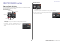
Improved gain indication
In the GAIN/PATCH field of the SELECTED CHANNEL VIEW screen, the analog gain and digital
gain of the head amp are both shown at all times.
■ A.GAIN indication
• Gain value
If digital gain is assigned to the GAIN knob, the analog gain value is shown here.
OVER indicator
Ø (Phase) indicator
The analog gain value is not shown if an input without a head amp
is patched to the input channel.
GAIN knob
+48V indicator
Gain value
HPF ON indicator
• Gain value
If analog gain is assigned to the GAIN knob, the digital gain value is shown here.
The GAIN knob, +48V indicator, and HPF ON indicator are not
shown if an input without a head amp is patched to the input
channel.
3
V1.7 Supplementary Manual
Centralogic section
Centralogic section
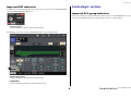
Improved HPF indication
The HPF status of an external head amp such as the R-series is now shown in the GAIN/PATCH field
of the SELECTED CHANNEL VIEW screen.
Improved DCA group indication
If 15 or more channels are registered in the DCA member indication of the OVERVIEW screen, you
can now use the multifunction knobs of the Centralogic section to scroll the channels.
• HPF ON indicator
Indicates the HPF on/off status of the external head amp.
The HPF/EQ popup screen now shows an HPF ON indicator and the cutoff frequency.
1
2
1 HA HPF ON indicator
Indicates the HPF on/off status of the external head amp.
2 FREQUENCY
Indicates the HPF cutoff frequency of the external head amp.
4
V1.7 Supplementary Manual
Input channels
■ Settings in the PORT SELECT popup window
Input channels
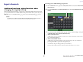
Additional head amp setting functions when
changing the input patching
1.
In the OVERVIEW screen, press the GAIN/PATCH field to access the GAIN/PATCH
popup window.
2.
Press the PATCH button (or INPUT PORT button) to access the PORT SELECT popup
window.
When you change the input patching, you can now choose whether the HA (Head Amp) settings of the
port you patched will be used, or whether the HA settings of the channel will be copied to the port you
patched.
Make this selection in the PORT SELECT popup window and the PATCH/NAME popup window.
1
2
NOTE
You can also choose whether the HA settings from CL Editor will be used without change or
copied from the channel. For details, refer to the CL Editor Owner’s Manual.
3.
Press a button in the HA INFO field to specify whether the HA settings of the port
or the HA settings of the channel will take priority.
1 TAKE FROM PORT button
The HA settings of the port will take priority. Even if you change the patching, the HA settings of
the port will remain unchanged.
2 TAKE FROM CHANNEL button
The HA settings of the channel will take priority. The HA settings of the port that had been
previously patched will be copied to the newly-patched port.
A confirmation dialog box will appear when you switch buttons.
If an input without a HA is patched to the input channel, the dialog box is not shown.
5
V1.7 Supplementary Manual
Input channels
If the channel’s HA settings are selected, the following HA settings will be copied from the channel
to the port that is patched. If you patch the input channel from an input that does not have these
settings (i.e., that does not have a HA), the default values will be specified.
HA setting
HA gain amount
Default value
–6 dB
HPF on/off
Off
Phantom power on/off
Off
Gain compensation on/off
Off
NOTE
If you’re newly patching a previously-unpatched input channel, the default values will be specified
if the HA INFO field’s TAKE FROM CHANNEL button is pressed.
■ Settings in the PATCH/NAME popup window
1.
In the OVERVIEW screen, press a channel number / channel name field to access
the GAIN/PATCH popup window.
2.
Make settings in the same way as in the PORT SELECT popup window.
6
V1.7 Supplementary Manual
Grouping and linking
Grouping and linking
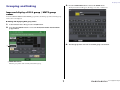
3.
Press the NAME EDIT button to access the NAME screen.
The keyboard window will appear, allowing you to enter or edit the text.
4.
The DCA group name is shown on the DCA group select button.
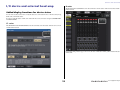
Improved display of DCA group / MUTE group
names
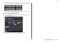
In the DCA/MUTE GROUP ASSIGN MODE popup window, the DCA group names and mute group
names can now be displayed.
■ Editing and displaying DCA group names
1.
In the Function Access Area, press the CH JOB button.
2.
Press the DCA GROUP button to access the DCA/MUTE GROUP ASSIGN MODE
popup window.
1
1 NAME EDIT button
Edits the group name of the currently selected DCA group.
7
V1.7 Supplementary Manual
Grouping and linking
■ Editing and displaying mute group names
Mute group names can be specified in the same way as for DCA groups.
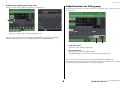
Added functions for DCA groups
Sends from an input channel to a bus whose send point is set to PRE can now be assigned to be muted
by a DCA group.
1
1 NAME EDIT button
Edits the group name of the currently selected MUTE group.
The registered group name is shown in the RECALL SAFE MODE popup window, the GLOBAL
RECALL SAFE popup window, and the GLOBAL PASTE window’s PATCH/NAME tab.
1
2
1 POST ONLY button
Specifies the object of muting as POST only.
2 PRE & POST button
Specifies the object of muting as PRE and POST.
The PRE&POST indicator is shown below a DCA group that has this setting.
The object of muting for a DCA group can be specified individually for each DCP group.
For channels that are assigned to more than one DCA group, muting any of the DCA groups will mute
that channel’s signal path (including sends to the corresponding buses).
8
V1.7 Supplementary Manual
Grouping and linking
Improvements in channel link display
A link indicator has been added to the CH LINK MODE popup window, making it easier to determine
the currently-assigned link group.
■ Accessing the CH LINK MODE popup window
1.
In the Function Access Area, press the CH JOB button.
2.
Press the CH LINK button to open the CH LINK MODE popup window.
Link indicator
3.
Channel display field
Use the [SEL] keys or the channel display field to select the channels that you want
to link; the link indicator will show the link group.
If a channel belonging to a link group is selected, the associated link group is shown. The LINK
PARAMETER field and SEND PARAMETER field show the link settings.
While you hold down the [SEL] key of a channel that does not belong to any link group, the link
indicator shows the link group that will be created next. The LINK PARAMETER field and SEND
PARAMETER field show the settings of the link group that had been previously displayed.
9
V1.7 Supplementary Manual
Monitor and Cue
Monitor and Cue
Meters
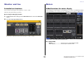
Extended cue functions
Added functions for meter display
The cue monitor level range has been expanded to –30 dB – +20 dB.
PRE GC METER and POST DIGITAL GAIN METER have been added to the METERING POINT
field of the METER screen. In addition, the name of PRE HPF has been changed to PRE D.GAIN.
Make this setting in the CUE popup window.
■ Accessing the CUE popup window
1.
In the Function Access Area, press the MONITOR button to access the MONITOR
screen.
2.
Press the CUE popup display button.
Use the knob to adjust the monitor level in the range of –30 dB – +20 dB.
Select the meter point at which the level will be detected.
■ For INPUT METER
• PRE GC ....................................... Immediately before GAIN COMPENSATION
• POST D.GAIN........................... Immediately after DIGITAL GAIN
10
V1.7 Supplementary Manual
Graphic EQ, Effects, and Premium Rack
MIX
1 2
2324
M
O
N
O MATRIX
L R (C) 1 2 7 8
ST
Graphic EQ, Effects, and Premium Rack
CUE
L R
CH 1-72{64,48}
To RACKIN PATCH
To OUTPUT PATCH
INSERT POINT
POST ON INSERT OUT
PRE FADER INSERT OUT
PRE EQ
INSERT OUT
CH INSERT OUT
1-72{64,48}
CH INSERT IN
1-72{64,48}
PRE D.GAIN
METER
Digital
GAIN
INPUT PATCH
72
{64,
48}
HPF
PRE HPF
OSCILLATOR
PRE HPF / PRE EQ / PRE FADER/POST ON
ON
DIRECT OUT 1-72{64,48}
LEVEL
PAN
POST DG
METER
DYNA1OUT
EQ OUT
DYNA2OUT
METER
METER
METER
GR METER
GR METER
PRE EQ
METER
INSERT
PRE EQ
INSERT OUT
ATT
4BAND
EQ
PRE EQ POST EQ
Keyin
Self PRE EQ
Self POST EQ
MIX21-24 OUT
CH[1-8,9-16,17-24,25-32,33-40,41-48, 49-56, 57-64, 65-72]POST EQ(CL5)
CH[1-8,9-16,17-24,25-32,33-40,41-48, 49-56, 57-64]POST EQ(CL3)
CH[1-8,9-16,17-24,25-32,33-40,41-48]POST EQ(CL1)
GATE
COMP
DUCK
COMPAND
EXPAND
DE-ESSER
COMP
KEYIN CUE
Keyin Filter
To MIX
PRE FADER
METER
To MIX
To MIX
INSERT
DELAY
Max
1000ms
VARI
STEREO
ON
LCR
INSERT
PAN MODE
PAN LINK
ON
MIX1,3...23
ON
MIX2,4...24
POST PAN L
ON
ON
POST PAN R
ON
ON
PRE EQ / PRE FADER / POST ON
ON
ON
LEVEL
ON
ON
LEVEL
ON
ON
LEVEL
PAN
To MATRIX PRE EQ / PRE FADER / POST ON
VARI
ON
ON
LEVEL
MATRIX1,3...7
ON
ON
LEVEL
MATRIX2,4...8
To MATRIX
ON
ON
LEVEL
PAN
(PRE FADER)PFL / (POST ON)AFL / POST PAN L
VARI
STEREO
ON
(PRE FADER)PFL / (POST ON)AFL / POST PAN R
ON
PRE EQ / PRE FADER / POST ON
In the EFFECT popup window, GEQ popup window, and PREMIUM RACK popup window, you can
now use the [SEL] keys to switch channels.
ST R
POST ON
POST ON
INSERT OUT
ON
PRE EQ / PRE FADER / POST ON
ST L
MONO(C)
TO LCR
ON
POST ON
Improvements in popup window operation
To OUTPUT PATCH
CSR
PRE FADER
PRE FADER
INSERT OUT
VARI
To MIX
LR MONO
POST PAN L
POST PAN R
TO MONO TO ST
LEVEL/
DCA1-16
FIXED
FIXED
STEREO
POST ON
METER
In the EFFECT popup window, pressing a top panel [SEL] key while editing an effect parameter will
switch the screen to the effect that is inserted in that channel. The same will occur in the GEQ popup
window and the PREMIUM RACK popup window. You can also switch from the EFFECT popup
window to the GEQ popup window or the PREMIUM RACK popup window.
The following items will change in conjunction with the channel being operated.
• Selected channel indication in the Function Access Area
• Channel being operated in the synchronized CL Editor
CUE L
CUE R
If no insert settings have been made in the channel to which you switched, a dialog box informing you
of this will appear.
Improved display for tap tempo function
If TAP TEMPO is assigned to a user defined key, and you are specifying the BPM (tempo value) by
pressing that key, a popup window like the following will now appear.
■ Tap tempo popup window
NOTE
This popup window will not appear if the EFFECT EDIT popup window in which you’re specifying
tap tempo is open.
11
V1.7 Supplementary Manual
I/O device and external head amp
I/O device and external head amp
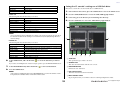
R-series
The Rio field of the I/O DEVICE screen shows indicators for the status of the R-series units and the
Dante network.
Added display functions for device status
You can now use the touch screen to verify the status of a connected CL series or R-series unit (except
the Ro8-D) or the Dante status.
In order to verify the status of an R-series unit from the console, it must be assigned to REMOTE HA
in DANTE SETUP.
CL series
The SETUP field of the DANTE SETUP screen shows indicators for the status of the CL series console
and the Dante network.
For firmware that predates support for V1.61, the version indication will be yellow and the indicator
will be unlit.
12
V1.7 Supplementary Manual
I/O device and external head amp
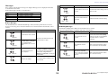
Messages
SYSTEM Indicators
Error, warning, and information messages are displayed. Messages are also displayed in the Dante
Controller Error Status field.
Each indicator lights or flashes as described below:
No call-out
The indicator is off.
Light
The indicator remains lit steadily.
Flash
The indicator continues to flash.
Flash x2
The indicator flashes twice cyclically.
Flash x3
The indicator flashes three times cyclically.
■ Error Messages
The SYSTEM indicators will remain lit/blinking as follows until the problem has been resolved.
If service is necessary, please contact the Yamaha service center listed in the CL5/CL3/CL1 owner’s
manual.
Description
The DIP switches are not set
correctly.
Check the DIP switch settings, and set
them correctly.
Dante flow number limit was
exceeded.
Examine the Dante network routing.
Flash
■ Warning Messages
The indicators will light and/or flash as shown until the cause is resolved.
If the green [SYNC] indicator is unlit, the unit’s clock is unconfirmed.
Possible Solution
SYNC Indicators
Description
Flash x3
The device has failed. Contact your
Yamaha dealer for repair.
Set the clock master and sampling
frequency correctly on the CL5/CL3/
CL1-native device or in Dante
Controller.
Dante Network circuit is
broken.
Make sure that the Ethernet cables
are not removed or short-circuited.
Other Dante-compatible
devices cannot be found due
to an incorrectly-wired Dante
Network.
The internal memory has
been corrupted.
Light
Make sure that the Ethernet cables
are connected correctly.
Flash
The MAC address setting has
been corrupted and no
communication can occur via
Dante.
Flash x3
Flash x2
Use the front-panel DIP switches to
set START UP MODE to REFRESH,
then restart the unit. If the problem
persists after setting START UP
MODE back to RESUME, consult your
Yamaha dealer.
Flash x3
UNIT ID is not unique.
Possible Solution
The word clock is not set
correctly.
An internal error has occurred.
Flash x2
Possible Solution
Flash
Light
SYSTEM Indicators
Description
Set a unique UNIT ID number for the
Dante network.
Light
13
V1.7 Supplementary Manual
I/O device and external head amp
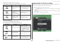
Improvements in I/O device settings
If the green indicator is flashing, the unit is the clock master.
If the green indicator is lit, the unit is the clock slave and the clock is synchronized.
SYNC Indicators
Light
or
flash
Description
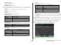
When mounting an I/O device on the Dante audio network, the settings and indications have been
improved so that the units can be differentiated by their device type.
Possible Solution
A non-GbE-compatible device
is connected.
When transferring audio via Dante,
use device that supports GbE.
The SECONDARY connector
has taken over
communications during
redundant network operation.
Check the circuit connected to the
PRIMARY connector.
The following device labels are detected as supported devices.
Y###-**********
# is a three-digit hexadecimal number (000–FFF) consisting of the digits 0–9 and the uppercase
characters A–F
* indicates any desired character (alphabetical uppercase or lowercase, numerals, or - (hyphen)
may be used)
Up to 31 characters including the ‘Y’ are supported.
Light
Light
or
flash
Flash
Light
or
flash
Flash x2
The DEVICE LIST field of the DEVICE SELECT popup window shows the device label and device type.
An abnormality has occurred
on the circuit connected to the
SECONDARY connector
during redundant network
operation.
Check the circuit connected to the
SECONDARY connector.
■ Information Messages
The status is shown by the lit/flashing state of the indicator.
If the orange [SYNC] indicator is unlit, the unit is operating normally.
If the green [SYNC] indicator is unlit, the unit’s clock is unconfirmed.
SYNC Indicators
Description
Explanation
Synchronization is occurring.
Please wait until the unit synchronizes
completely. It may take up to
45 seconds to synchronize completely.
(If the DIP switches of an R-series unit
are set to REFRESH, synchronization
will not be completed until the CL
series unit that is set to “with RECALL”
has started up.)
The unit is functioning
correctly as the word clock
master.
The unit is operating as the word clock
master.
The unit is functioning
correctly as the word clock
slave.
The unit is operating as the clock slave
and the clock is synchronized.
Light
Flash
Light
14
V1.7 Supplementary Manual
User settings
User settings
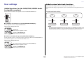
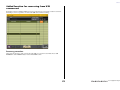
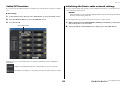
Added custom fader bank functions
Custom fader bank settings can now be stored/recalled for individual scenes.
Custom fader bank settings are separated into areas for each model and stored together in the scene
data.
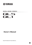
Added functions for the GAIN/PAN/ASSIGN knobs
(assignable encoders)
Custom fader bank settings
Functions have been added to the assignable encoders in SENDS ON FADER mode.
CL5
Recall
■ If ASSIGN is selected by the top panel [GAIN/PAN/ASSIGN] key
Use the assignable encoders to adjust the channel levels.
Store
CL5 console
CL3
Recall
Store
CL3 console
CL1
Recall
Store
CL1 console
NOTE
Channel name display indication
Custom fader bank settings differ between models, and are not compatible. For example, custom
fader bank settings included in a scene stored by the CL5 will not be reproduced if that scene is
recalled on the CL3 or CL1. The settings must be created and stored on the CL3 or CL1.
Channel level
Adjust using the assignable encoders.
Send level to MIX/MATRIX bus
Adjust using the top panel faders.
■ If PAN is selected by the top panel [GAIN/PAN/ASSIGN] key
Use the assignable encoders to adjust the pan of the send from the channel to the MIX/MATRIX bus
(buses that are assigned to stereo send in the BUS SETUP screen).
Channel name display indication
Pan of the send from the channel to the MIX/MATRIX bus
Adjust using the assignable encoders.
Send level to MIX/MATRIX bus
Adjust using the top panel faders.
15
V1.7 Supplementary Manual
User settings
■ Focus function
For the focus function, you can specify for each scene whether custom bank settings will be recalled
(loaded).
1.
Press the SCENE field of the Function Access Area.
2.
Press the FOCUS tab at the bottom of the SCENE LIST window.
4.
Press a button in the FOCUS PARAMETER field to access the FOCUS PARAMETER
popup window.
5.
Verify the object of focus.
6.
Press the CLOSE button to close the popup window; then perform a recall
operation.
Custom bank settings are included in OTHER PARAMs.
3.
Press the SET button of the scene for which you want to make settings; the FOCUS
RECALL popup window will appear.
16
V1.7 Supplementary Manual
User settings
■ Recall Safe function
In the Recall Safe function, you can specify that custom bank settings of all scenes will be globally
excluded from recall operations.
■ Global Paste function
The global paste function lets you copy and paste the custom bank settings of the current scene to scene
data in memory.
1.
In the Function Access Area, press the CH JOB button to access the CH JOB popup
window.
1.
In the Function Access Area, press the SCENE field to access the SCENE LIST
window.
2.
Press the RECALL SAFE button to access the RECALL SAFE MODE popup window.
2.
3.
Press the GLOBAL PASTE button located in the upper part of the SCENE LIST
window to open the GLOBAL PASTE window.
Press the GLOBAL RECALL SAFE field to access the GLOBAL RECALL SAFE popup
window.
3.
Select the PATCH/OTHERs tab.
4.
Select the CUSTOM FADER BANK button.
5.
In the DESTINATION SCENE area, select the range of paste-destination scenes.
6.
Press the PASTE button.
4.
Press the CUSTOM FADER BANK button to specify it as the object of recall safe.
5.
Press the CLOSE button to close the popup window; then perform a recall
operation.
NOTE
• If the internal data of the CL console was loaded from a USB flash drive as a package, load the
user authentication key as necessary. The custom fader bank settings of the user who loaded the
data will be applied.
• When in PREVIEW mode, changes from CL Editor are not reflected immediately. They will be
applied when you exit PREVIEW mode.
17
V1.7 Supplementary Manual
User settings
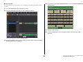
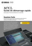
Added load/save functions
3 DESTINATION field
CL series settings can now be loaded individually from a USB flash drive, or saved individually to a USB
flash drive.
4 Data selection knob
Indicates the load-destination.
This knob selects the data shown in the field.
Loading settings from a USB flash drive
5 MULTI SELECT button
By pressing this button you can make a selection containing multiple items of data.
Follow the steps below to load CL settings from the USB flash drive into the CL series console.
1.
In the Function Access Area, press the SETUP button to access the SETUP screen.
2.
Press the SAVE/LOAD button to access the SAVE/LOAD popup window.
3.
To select the file that you want to load, press the name of the desired file in the file
list, or rotate the corresponding multifunction knob on the panel.
4.
6 SELECT ALL button
Press this button to select all items.
7 CLEAR ALL button
Press this button to clear all selections.
5.
Press the LOAD button to access the LOAD SELECT popup window.
Press the tabs and buttons of the TYPE field to select the type of data that you want
to load.
The content shown in the TYPE field will vary depending on the tab you select.
• ALL tab
All items will be the target of the operation.
1
• SCENE tab
Scene memories will be the target of the operation.
• INPUT/OUTPUT tab
The following table lists the items that you can select.
Buttons
2
3
Data content
IN CH LIB
Input channel library
OUT CH LIB
Output channel library
IN EQ LIB
Input EQ library
OUT EQ LIB
Output EQ library
DYNA LIB
Dynamics library
• EFFECT/GEQ tab
The following table lists the items that you can select.
Buttons
4
5
6
7
4
Data content
EFFECT LIB
Effect library
GEQ LIB
GEQ library
• PREMIUM tab
The following table lists the items that you can select.
1 TYPE field
Selects the type of data to be loaded.
Buttons
2 SOURCE field
This area lists the data that is saved on the USB flash drive.
18
Data content
5033 LIB
Portico 5033 library
5043 LIB
Portico 5043 library
U76 LIB
U76 library
V1.7 Supplementary Manual
User settings
Buttons
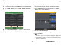
Saving the CL console’s settings on a USB flash drive
Data content
Opt-2A LIB
Opt-2A library
EQ-1A LIB
EQ-1A library
DynaEQ LIB
DynamicEQ library
Here’s how to save the CL console’s internal data on a USB flash drive.
• SETUP tab
The following table lists the items that you can select.
Buttons
1.
In the Function Access Area, press the SETUP button to access the SETUP screen.
2.
Press the SAVE/LOAD button to access the SAVE/LOAD popup window.
3.
If necessary, press the directory icon and change the directory.
4.
Press the SAVE button to access the SAVE SELECT popup window.
Data content
MIXER SETUP
Mixer setup
OUTPUT PORT
Output ports
MONITOR
CUE/MONITOR/OSCILLATOR/TALKBACK
MIDI SETUP
MIDI Setup
MIDI PGM
MIDI program changes
MIDI CTL
MIDI control changes
Dante In Patch
DANTE input patch library
1
NOTE
If you load output port items individually, the settings of the channel assigned to the port will not
be reflected. Recall them after loading a scene that includes input/output patching with those
channel settings.
2
3
• ADMIN tab
The following table lists the items that you can select.
Buttons
Data content
ADMIN PREF
PREFERENCE (For administrator)
ADMIN UDEF
USER DEFINED KEYS/USER DEFINED KNOBS (For administrator)
ADMIN FADER
CUSTOM FADER BANK (For administrator)
GUEST PREF
PREFERENCE (For guest)
GUEST UDEF
USER DEFINED KEYS/USER DEFINED KNOBS (For guest)
GUEST FADER
CUSTOM FADER BANK (For guest)
GUEST LEVEL
USER LEVEL (For guest)
4
5
6
7
4
1 TYPE field
6.
In the SOURCE field, add a check mark ( ) to select the data that you want to
load.
If you want to load multiple items of data in a single operation, press the MULTI SELECT button.
7.
In the DESTINATION field, add a check mark (
8.
Press the LOAD button.
This specifies the types of data to be saved.
2 SOURCE field
This shows the internal data of the CL series console.
) to the load-destination.
3 DESTINATION field
Indicates the save-destination.
4 Data selection knob
NOTE
This knob selects the data shown in the field.
If the number of loadable data items in the DESTINATION list is less than the number of items
being loaded, the allowable number of data items will be loaded.
5 MULTI SELECT button
By pressing this button you can make a selection containing multiple items of data.
19
V1.7 Supplementary Manual
User settings
6 SELECT ALL button
• SETUP tab
The following table lists the items that you can select.
Press this button to select all items.
Buttons
7 CLEAR ALL button
MIXER SETUP
Press this button to clear all selections.
5.
Press the tabs and buttons of the TYPE field to select the type of data that you want
to save.
The content shown in the TYPE field will vary depending on the tab you select.
• ALL tab
All items will be the target of the operation.
• SCENE tab
Scene memories will be the target of the operation.
Buttons
Mixer setup
OUTPUT PORT
Output ports
MONITOR
CUE/MONITOR/OSCILLATOR/TALKBACK
MIDI SETUP
MIDI Setup
MIDI PGM
MIDI program changes
MIDI CTL
MIDI control changes
Dante In Patch
DANTE input patch library
NOTE
• If you save output port items individually, the settings for the channel assigned to the port will not
be saved. You will also need to save the scene that includes the input/output patching for those
channel settings.
• Items that are included in the ADMIN tab when loading items individually will be included in ALL
when saving.
• INPUT/OUTPUT tab
The following table lists the items that you can select.
IN CH LIB
Data content
Data content
Input channel library
OUT CH LIB
Output channel library
IN EQ LIB
Input EQ library
OUT EQ LIB
Output EQ library
DYNA LIB
Dynamics library
• EFFECT/GEQ tab
The following table lists the items that you can select.
Buttons
6.
In the SOURCE field, add a check mark ( ) to select the data that you want to
save.
If you want to save multiple items of data in a single operation, press the MULTI SELECT button.
7.
In the DESTINATION field, add a check mark (
8.
Press the SAVE button to access the FILE SAVE popup window.
9.
Enter a file name or comment, and press the SAVE button.
) to the save-destination.
Data content
EFFECT LIB
Effect library
GEQ LIB
GEQ library
• PREMIUM tab
The following table lists the items that you can select.
Buttons
Data content
5033 LIB
Portico 5033 library
5043 LIB
Portico 5043 library
U76 LIB
U76 library
Opt-2A LIB
Opt-2A library
EQ-1A LIB
EQ-1A library
DynaEQ LIB
DynamicEQ library
20
V1.7 Supplementary Manual
User settings
Added function for recovering from USB
overcurrent
Even if the connection with the USB device was stopped because an overcurrent condition occurred at
the USB port, it is now possible to reconnect the USB device without restarting.
Recovery procedure
After removing the cause of the overcurrent at the USB port, press the location that shows “USB
REMOUNT” at the FORMAT button of the SAVE/LOAD screen.
21
V1.7 Supplementary Manual
Other functions
Other functions
Added channel color
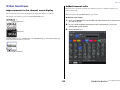
Improvements to the channel name display
Black can now be specified as a channel color. If black is selected for a channel, its channel color
indicator will be unlit.
Improvements have been made to the channel name display and channel color indicator.
Make this setting in the CH COLOR/ICON popup window.
■ Channel color setting
The channel on/off status is now shown in SENDS ON FADER mode.
1.
Access the OVERVIEW screen that includes the input channel whose channel color
you want to specify.
2.
Press the channel number/channel name field of that channel to access the
PATCH/NAME popup window.
3.
Select a channel color.
Channel on
Channel off
If NAME DISPLAY is set to “NAME ONLY” in the PREFERENCE page of the USER SETUP popup
window, the channel number is now shown.
Channel number indication
22
V1.7 Supplementary Manual
Other functions
Added GPI functions
Initializing the Dante audio network settings
You can now select the attributes (latched or unlatched) of an external switch connected to a GPI IN
port.
It is now possible for Dante-related settings to also be initialized to their factory-set state when an error
occurs on the Dante audio network.
NOTICE
■ GPI settings
When you initialize, all console settings including the Dante audio network settings that had been
previously saved in memory will be lost.
1.
In the Function Access Area, press the SETUP button to access the SETUP screen.
2.
Press the MIDI/GPI button to access the MIDI/GPI screen.
Proceed with the following operation only if you are very sure you want to do this!
3.
Press the GPI tab.
1.
While holding down the SCENE MEMORY [STORE] key and [INC] key on the panel,
turn on the power to the CL console.
2.
A message indicates that initialization is complete; press the CLOSE button.
Switch attribute button
Each time you press a switch attribute button, its indication will alternate between LATCH and
UNLATCH.
LATCH (a switch that alternately turns on/off each time it is pressed) is selected.
UNLATCH (a switch that is on only while pressed and is off when released) is selected.
23
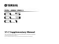
V1.7 Supplementary Manual
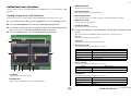
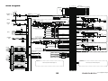
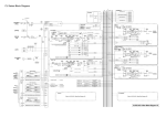
Block Diagram
MIX
1 2
2324
M
O
N
O MATRIX
L R (C) 1 2 7 8
ST
CUE
L R
CASCADE OUT
MIX CASCADE OUT1-24
To OUTPUT PATCH
To OUTPUT PATCH
CASCADE IN
To OUTPUT PATCH
To OUTPUT PATCH
STEREO CASCADE OUT L,R,MONO(C)
SLOT1 1-16
SLOT2 1-16
SLOT3 1-16
CASCADE
IN
SELECT
+48V MASTER
+48V
MATRIX CASCADE OUT1-8
CUE CASCADE OUT LR
HA
2
TALKBACK
INPUT
METER
+
-
1
3
1
DANTE
INPUT
To OUTPUT PATCH
ON
INPUT
SELECT
OSCILLATOR
Sine Wave
Pink Noise
Burst Noise
INPUT
PATCH
64
To RACKIN PATCH
To OUTPUT PATCH
[OMNI IN]
[1-8]
OMNI IN
METER
+
-
1
3
8
GAIN/TRIM
PRE HPF / PRE EQ / PRE FADER/POST ON
DYNA1OUT
EQ OUT
DYNA2OUT
METER
METER
METER
GR METER
GR METER
PRE EQ
METER
HPF
PRE HPF
OSCILLATOR
To MONITOR
SELECT
INSERT
ATT
PRE EQ
INSERT OUT
GATE
COMP
DUCK
COMPAND
EXPAND
DE-ESSER
COMP
KEYIN CUE
Keyin Filter
4BAND
EQ
PRE EQ POST EQ
Keyin
Self PRE EQ
Self POST EQ
MIX21-24 OUT
CH[1-8,9-16,17-24,25-32,33-40,41-48, 49-56, 57-64, 65-72]POST EQ(CL5)
CH[1-8,9-16,17-24,25-32,33-40,41-48, 49-56, 57-64]POST EQ(CL3)
CH[1-8,9-16,17-24,25-32,33-40,41-48]POST EQ(CL1)
To CASCADE IN
SELECT
METER METER METER
SLOT2
SLOT3
SLOT2 1-16
16
3
4
DECODER
2
USB
GEQ RACK1(GEQ1)
METER RACK IN
METER RACK OUT
METER RACK IN A
METER RACK IN B
METER RACK OUT A
METER RACK OUT B
Flex15GEQ
ST R
ON
POST PAN R
ON
ON
ON
LEVEL
ON
LEVEL
ON
LEVEL
PAN
PRE EQ / PRE FADER / POST ON
PRE D.GAIN
METER
Digital
GAIN
HPF
ATT
4BAND
EQ
ON
LEVEL
MATRIX1,3...7
ON
LEVEL
MATRIX2,4...8
To MATRIX
ON
ON
LEVEL
PAN
GEQ RACK2-16(GEQ2-16) (same as GEQ RACK1)
EFFECT
RACK IN
PATCH
EFFECT RACK1(FX1)
PRE EQ POST EQ
INSERT POINT
METER RACK IN
(PRE FADER)PFL / (POST ON)AFL / POST PAN R
ON
LR MONO
POST PAN L
POST PAN R
TO MONO TO ST
LCR
PAN MODE
CH INSERT IN 1-72{64,48}
To CH INSERT IN
METER RACK OUT
INSERT IN
PATCH
(OUTPUT CH)
METER RACK OUT A
METER RACK OUT B
SLOT1 1-16
SLOT2 1-16
SLOT3 1-16
METER RACK OUT L
METER RACK OUT R
GEQ1-16
OUT
A(L)/B(R)
Flex15GEQ
EFFECT
EFFECT CUE
FX1 IN
A(L)/B(R)
EFFECT RACK2-8(FX2-8) (same as EFFECT RACK1)
FX1 OUT
A(L)/B(R)
MIX INSERT IN 1-24
24
3
STEREO INSERT IN L,R,MONO(C)
MATRIX INSERT IN 1-8
To MIX INSERT IN
To STEREO INSERT IN
PAN/BAL
LR MONO
PAN MODE TO ST TO MONO
LCR
POST ON
METER
PRE FADER
METER
LEVEL
BAL
INSERT
PRE FADER
INSERT OUT
STEREO OUT
L,R,MONO(C)
ON
INSERT
PRE FADER
POST ON
INSERT OUT
Keyin
Self PRE EQ/Self POST EQ/MIX21-24 OUT/
ST(L,R,MONO(C)) POST EQ
To OUTPUT PATCH
To MONITOR SELECT
POST ON
(PRE FADER)PFL / (POST ON)AFL
LEVEL
ON
LEVEL
ON
LEVEL
ON
ST L
PRE FADER / POST ON To MATRIX
VARI
PRE FADER / POST ON
PAN/BAL
To MATRIX
VARI
STEREO
CSR
POST ON
MATRIX 1-8
INSERT POINT
MATRIX
INSERT OUT 1-8
MATRIX
INSERT IN 1-8
MIX2,4...24
PRE EQ
METER
MATRIX1,3...7
SAME as INPUT1-72{64,48}
POST ON INSERT OUT
PRE FADER INSERT OUT
PRE EQ
INSERT OUT
To RACKIN PATCH
To OUTPUT PATCH
MIX1,3...23
EQ OUT
DYNA OUT
METER
METER
GR METER
MATRIX2,4...8
ON
CUE L
CUE R
ON
KEYIN CUE
VARI
VARI
STEREO
ST R
SAME as INPUT1-72{64,48}
EFFECT CUE
4BAND
EQ
CUE ON
PAN LINK
To MIX
ATT
COMP
COMPAND
EXPAND
PRE EQ POST EQ
MATRIX2,4...8
MONO(C)
TO LCR
EQ OUT
DYNA OUT
METER
METER
GR METER
MATRIX1,3...7
PRE EQ
INSERT OUT
CUE ON
PR1-8 OUT
A(L)/B(R)
OMNI IN 1-8
METER RACK IN L
METER RACK IN R
PRE FADER
To MATRIX
To MATRIX
POST ON INSERT OUT
PRE FADER INSERT OUT
PRE EQ
INSERT OUT
INSERT
(PRE FADER)PFL / (POST ON)AFL / POST PAN L
SLOT1 1-16
SLOT2 1-16
SLOT3 1-16
31BandGEQ
METER RACK IN A
METER RACK IN B
POST ON
METER
DELAY
Max
1000ms
PRE FADER / POST ON
PRE EQ
METER
PRE EQ
INSERT OUT
CUE L
LEVEL/
DCA1-16
PRE FADER / POST ON
POST ON
CUE R
To MATRIX
INSERT IN
PATCH
(INPUT CH)
72
KEYIN CH1-72{64,48}
FX1-8 OUT L/R
PR1-8 OUT L/R
RECORDER INL/R
RECORDER CUEPLAYBACK
OUT L/R
KEYIN CUE
SELECT
ON
EFFECT CUE
SELECT
ON
RECORDER CUE
SELECT
ON
ATT
4BAND
EQ
PRE EQ POST EQ
COMP
COMPAND
EXPAND
POST ON
METER
PRE FADER
METER
LEVEL
ON
MATRIX OUT 1-8
INSERT
INSERT
PRE FADER
INSERT OUT
BAL
PRE FADER
Keyin
Self PRE EQ/Self POST EQ/MIX21-24 OUT/
MATRIX1-8 POST EQ
POST ON
INSERT OUT
To OUTPUT PATCH
To MONITOR SELECT
POST ON
(PRE FADER)PFL / (POST ON)AFL
To MATRIX INSERT IN
8
OUTPUTS
CUE / MONITOR
FX2-8 OUT
A(L)/B(R)
Refer to CL5/CL3/CL1 Mixer Block Diagram 2/2
PREMIUM
RACK IN
PATCH
ON
ON
INSERT
PRE FADER
METER
(21-24)To KEYIN
To RACKIN PATCH
To OUTPUT PATCH
To MONITOR SELECT
POST ON
STEREO L,R,MONO(C)
ON
GATE
COMP
DUCK
COMPAND
EXPAND
DE-ESSER
COMP
KEYIN CUE
Keyin Filter
ON
LEVEL
LEVEL
STEREO
INSERT OUT L,R,MONO(C)
STEREO
INSERT IN L,R,MONO(C)
ON
DYNA1OUT
EQ OUT
DYNA2OUT
METER
METER
METER
GR METER
GR METER
POST ON
INSERT OUT
Keyin
Self PRE EQ/Self POST EQ/MIX21-24 OUT/
MIX(1-8,9-16,17-24) POST EQ
TO LCR
To RACKIN PATCH
To OUTPUT PATCH
To MATRIX PRE EQ / PRE FADER / POST ON
VARI
PRE EQ / PRE FADER / POST ON
MIX OUT1-24
INSERT
PRE FADER
CSR
FX1-8 OUT
A(L)/B(R)
GEQ2-16 IN
A(L)/B(R)
FX2-8 IN
A(L)/B(R)
MIX2,4...24
ON
ON
ON
INSERT
PRE FADER
INSERT OUT
ST L
PAN LINK
OMNI IN 1-8
31BandGEQ
MATRIX OUT
1-8
LEVEL
MATRIX2,4...8
MONO(C)
ON
BAL
(PRE FADER)PFL / (POST ON)AFL
MATRIX1,3...7
MIX1,3...23
ON
Keyin
Self PRE EQ
Self POST EQ
MIX21-24 OUT
ST IN 1L-8R POST EQ
STEREO OUT
L,R,MONO(C)
CH
INSERT OUT
1-72{64,48}
MONO(C)
LEVEL
PAN/BAL
PAN/BAL
PRE HPF
MIX OUT
1-24
CUE ON
ON
POST PAN L
4BAND
EQ
POST ON
METER
PRE FADER
METER
ST R
POST ON
POST ON
INSERT OUT
ON
COMP
COMPAND
EXPAND
ST L
CSR
PRE FADER
PRE FADER
INSERT OUT
ATT
PRE EQ
INSERT OUT
PAN MODE
EQ OUT
DYNA OUT
METER
METER
GR METER
PRE EQ POST EQ
To OUTPUT PATCH
TO LCR
LCR
INSERT
ON
ON
OSCILLATOR
GEQ1 IN
A(L)/B(R)
ON
DELAY
Max
1000ms
ON
(PRE FADER)PFL / (POST ON)AFL / POST PAN R
16
MATRIX
INSERT OUT
1-8
POST PAN L
POST PAN R
TO MONO TO ST
LEVEL/
DCA1-16
INSERT
PRE EQ / PRE FADER / POST ON
(PRE FADER)PFL / (POST ON)AFL / POST PAN L
PRE EQ
METER
RECORDER CUE
GEQ
RACK IN
PATCH
LR MONO
VARI
VARI
STEREO
ON
To MONITOR SELECT
MIX
INSERT OUT
1-24
STEREO
INSERT OUT
L,R,MONO(C)
POST ON
METER
ST IN 1L – 8R
GAIN
POST ON INSERT OUT
PRE FADER INSERT OUT
PRE EQ
INSERT OUT
PRE EQ
METER
SLOT3 1-16
16
PLAYBACK OUT
METER
2
DIRECT OUT 1-72{64,48}
LEVEL
To MIX
VARI
STEREO
PR1-2 OUT
A(L)/B(R)
1
PRE FADER
METER
FIXED
To MIX
To MIX
SLOT1 1-16
16
FX1-8 OUT
A(L)/B(R)
[PLAYBACK
OUT]
ON
POST ON
To MIX
FIXED
STEREO
SLOTIN SLOTIN SLOTIN
[SLOT]
HPF LPF
PAN
Digital
GAIN
72
{64,
48}
SLOT1
MIX
INSERT OUT 1-24
MIX
INSERT IN 1-24
INSERT
POST ON INSERT OUT
PRE FADER INSERT OUT
PRE EQ
INSERT OUT
POST DG
METER
PRE D.GAIN
METER
OMNI IN
1-8
AD
INSERT POINT
To RACKIN PATCH
To OUTPUT PATCH
INSERT POINT
CH INSERT OUT
1-72{64,48}
CH INSERT IN
1-72{64,48}
HA
+48V
MIX 1-24
ON
CH 1-72{64,48}
DANTE IN
1-64
2
OSC
METER
LEVEL
DANTE
IN
METER
To OUTPUT PATCH
TALKBACK
TB INPUT
DANTE IN 1-64
OMNI IN 1-8
AD
TALKBACK
LEVEL
[DANTE]
To OUTPUT PATCH
To OUTPUT PATCH
To OUTPUT PATCH
To OUTPUT PATCH
ON
+48V
[TALKBACK
INPUT]
To OUTPUT PATCH
To OUTPUT PATCH
To OUTPUT PATCH
Refer to CL5/CL3/CL1 Mixer Block Diagram 2/2
PREMIUM RACK1(PR1)
METER RACK IN L
METER RACK IN R
METER RACK OUT L
METER RACK OUT R
PROCESSOR
PR1 IN
A(L)/B(R)
PR2-8 IN
A(L)/B(R)
EFFECT CUE
PREMIUM RACK2-8 (same as PREMIUM RACK1)
PR1 OUT
A(L)/B(R)
PR2-8 OUT
A(L)/B(R)
24
V1.7 Supplementary Manual
CUE / MONITOR
MONITOR DELAY AUTO BYPASS
CUE TRIM
(INPUT/OUTPUT/DCA)
CUE L BUS
CUE L
CUE R BUS
CUE R
CUE ON
MONO
CUE OUT ON
METER CUE L
METER CUE R
DELAY
(MAX:1000ms)
DELAY
(MAX:1000ms)
CUE OUT L
To OUTPUT PATCH
CUE OUT R
To OUTPUT PATCH
CUE OUT
LEVEL
CUE LOGIC
DEFINE
MIX
(MAX:8ch)
MONITOR L
MONO
METER MONITOR L
MONITOR R
METER MONITOR R
MONITOR MONO(C)
METER MONITOR MONO(C)
ON
ON
MONITOR OUT MONO(C)
DELAY
(MAX:1000ms)
+MONO(C)
To PHONES OUT
To PHONES OUT
MONITOR OUT R
DELAY
(MAX:1000ms)
CUE INTERRUPTION
PHONES L
PHONES R
MONITOR OUT L
DELAY
(MAX:1000ms)
DIMMER
MONITOR SELECT
STEREO OUT L,R
STEREO OUT MONO(C)
STEREO OUT L,C,R
STEREO OUT L,R
STEREO OUT MONO(C)
MIX OUT1-24
MATRIX OUT1-8
DELAY
(MAX:1000ms)
DELAY
(MAX:1000ms)
OMNI IN 1/2
OMNI IN 3/4
OMNI IN 5/6
OMNI IN 7/8
PLAYBACK OUT
OMNI IN 1/2
OMNI IN 3/4
OMNI IN 5/6
OMNI IN 7/8
PLAYBACK OUT
PHONES
LEVEL LINK
To OUTPUT PATCH
To OUTPUT PATCH
To OUTPUT PATCH
An output port delay becomes invalid by
assigning a monitor out to the output port.
TALKBACK ON
MONITOR MONITOR
MONITOR DIMM ON LEVEL
FADER
OUTPUTS
MIX CASCADE OUT 1-24
STEREO CASCADE OUT L,R,MONO(C)
MATRIX CASCADE OUT 1-8
CUE CASCADE OUT L,R
DIRECT OUT 1-72{64,48}
MIX OUT 1-24
STEREO OUT L,R,MONO(C)
MATRIX OUT 1-8
PHONES OUT LR
OUTPUT
PATCH
2
Tip
Ring
Sleeve
DA
[PHONES]
PHONES LEVEL
MONITOR OUT L,R,MONO(C)
CUE OUT L,R
GAIN TRIM
DELAY
(MAX:1000ms)
METER
SLOT1OUT
DELAY
(MAX:1000ms)
METER
SLOT2OUT
DELAY
(MAX:1000ms)
METER
SLOT3OUT
OUTPUT
PATCH
DELAY
(MAX:1000ms)
METER OMNI OUT
OUTPUT
PATCH
DELAY
(MAX:1000ms)
METER DANTE OUT
CH INSERT OUT 1-72{64,48}
MIX INSERT OUT 1-24
STEREO INSERT OUT L,R,MONO(C)
MATRIX INSERT OUT 1-8
16
SLOT1
16
SLOT2
[SLOT]
SLOT3
16
GAIN TRIM
8
DA
2
+
-
1
3
[OMNI OUT] (1-8)
GAIN
OUTPUT
PATCH
DELAY
(MAX:1000ms)
DANTE
OUTPUT
64
METER
DIGITAL
OUT
[DANTE OUT] (1-64)
GAIN TRIM
2
DIT
[DIGITAL OUT]
AES/EBU
RECORDER IN
METER
STEREO L
MONO(C)
OUTPUT
PATCH
2
RECORDER CUE
ENCODER
GAIN
1
2
3
4
[2TR RECORDER]
USB
STEREO R
25
V1.7 Supplementary Manual
Yamaha Pro Audio Global Web Site
http://www.yamahaproaudio.com/
Yamaha Manual Library
http://www.yamaha.co.jp/manual/
C.S.G., PA Development Division
© 2013 Yamaha Corporation
310IP-A0