1
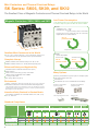
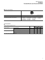
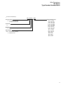
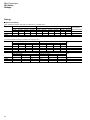
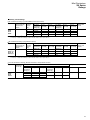
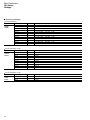
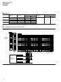
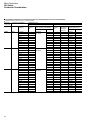
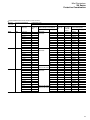
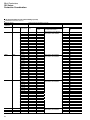
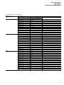
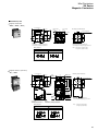
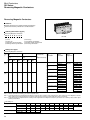
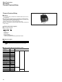
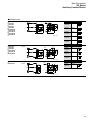
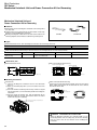
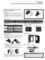
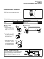
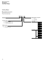
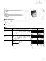
MOTOR CONTROL
Mini-Contactors and Thermal Overload Relays
SK Series
62C1-E-0022
Mini-Contactors and Thermal Overload Relays
SK Series: SK06, SK09, and SK12
The Smallest Class of Magnetic Contactors and Thermal Overload Relays in the World
Magnetic Contactors: SK06, SK09, and SK12
Low Power Consumption
The operating coil uses a newly designed electromagnet
section to help save power for both AC and DC models.
DC Coil
Standard DC coil : 2.4W
Low-power DC coil : 1.2W
* Up to two auxiliary contacts can be added.
48mm
Directly drive these Contactors with DC transistor
outputs from PLCs or other devices.
86% of
previous models
49mm
45mm
Comparison with FUJI SJ Series
Smallest Mini-Contactors in the World
AC Coil
Power consumption
At 45 × 48 × 49mm (W×H×D), these Contactors achieve the
same dimensions for AC-operated and DC-operated models.
Complete Lineup
Models available with 3 different ratings: 6A, 9A, or 12A.
Models available with AC, DC, or low-power operating coils.
Inrush: 22VA
Sealed: 4.5VA
69% of
previous models
75% of
previous models
Enhanced Safety and Applicability
Comparison with FUJI SC-M Series
Standard-feature removable terminal cover (IP20).
Mirror contacts.
Short-circuit current rating (SCCR): 50kA 480V
* When used in combination with an MMS.
UL ratings: 480V 5HP
IEC ratings: 480V 12A (AC-3)
Many Options
Auxiliary Contact Blocks (2-pole, 4-pole, or compact 2-pole)
Coil Surge Suppression Unit
Interlock Unit
Environment
Link Modules (for use in combination with an MMS).
RoHS Compliant (EU Restric tion of the Use of Cer tain
Hazardous Substances in Electrical and Electronic Equipment)
The materials used do not contain any of the six substances that are
specified in the RoHS Directive or have less than the specified content
percentages of those substances.
Auxiliary Contact Blocks
(2-pole or 4-pole)
Auxiliary Contact Blocks
(compact 2-pole)
Coil Surge Suppression Unit
Interlock Unit
International Safety Standards for Standard Models
International standards for standard models: IEC, GB (CCC),
JIS, UL, and TÜV
Standard Compliance
Product
Type
Compliant Standards
IEC
International
Certified Standards
EN
Europe
JIS
Japan
EN
JIS
■
■
■
■
■
■
■
■
EC
Directives
Certifying
Body
TÜV
Germany
UL
USA
CSA
Canada
GB
China
CE Marking
Europe
■
■
■
■
■
■
■
■
■
■
■
■
■
■
■
■
TÜV Rheinland
Magnetic
Contactors
Thermal Overload
Relays
Note: Legend
2
SK □ A
SK □ G
SK □ L
TK12
■
■
■
■
■ : Compliance with standard models.
■
■
■
■
SK Series
SK06, SK09, and SK12
NEW
Thermal Overload Relays: TK12
Enhanced Safety
2E Thermal Overload Relay overload and phase-loss protection
with standard models.
A standard-feature transparent cover that serves as a dial lock
and that also protects against unintentional operation of the reset
button.
Transparent cover
・Dial lock.
・Protects against unintentional
changes on the reset method.
Easier Wiring
① Connection to Round Crimp Terminals
Downsizing
Standard-feature
easy-to-remove
terminal cover.
Combine a Thermal Overload Relay with a Magnetic Contactor for
Meaningful Downsizing
Footprint
87% of
previous models
② Terminal Arrangement for No Interference between Power Lines
for Main and Auxiliary Circuits When Wiring
97.5mm
TK12
Previous Models
The difficulties in wiring caused by
the previous terminal arrangement
have been eliminated.
The main circuits were difficult to wire
because the screwdriver had to be held
at an angle due to interference from the
auxiliary circuits.
Volume
55% of
previous models
Main
terminals
55mm
45mm
Comparison with FUJI SJ Series
Auxiliary Relays: SKH4
Auxiliary
terminals
Main
terminals
Downsizing
Both AC-operated and DC-operated (2.4W and 1.2W) models are available and have the
same shape as the Magnetic Contactors.
Add up to eight contacts with the addition of Auxiliary Contact Blocks (2-pole or 4-pole).
A compact, 2-pole Auxiliary Contact Blocks with a reduced depth dimension is also available.
High Reliability and Safety
Lineup includes models with bifurcated contact for high reliability (standard models) and highcapacity models (single button contact).
48mm
Auxiliary Relays with linked contacts.(Complies with requirements of IEC60947-5-1 Annex L.)
Contact specifications
[arrangement]
49mm
45mm
Type
Conventional free air thermal current
(Rated continuous current)
100-120V
Coil load and rated
200-240V
operational current
380-440V
(AC-15)
500-600V
Minimum voltage and current
Linked contact
High-reliability
(standard) models
[bifurcated contact]
SKH4 □
10A
High-capacity
models
[single button contact]
SKH4 □ H
10A
3A
3A
1A
0.5A
5V DC, 3mA
6A
6A
6A
3A
24V DC, 10mA
○
3
Catalog Disclaimer
The information contained in this catalog does not constitute an express or implied warranty of quality, any warranty of
merchantability of fitness for a particular purpose is hereby disclaimed.
Since the user's product information, specific use application, and conditions of use are all outside of Fuji Electric FA
Components & Systems'control, it shall be the responsibility of the user to determine the suitability of any of the
products mentioned for the user's application.
One Year Limited Warranty
The products identified in this catalog shall be sold pursuant to the terms and conditions identified in the
"Conditions of Sale" issued by Fuji Electric FA with each order confirmation.
Except to the extent otherwise provided for in the Conditions of Sale issued by Fuji Electric FA, Fuji Electric FA
warrants that the Fuji Electric FA products identified in this catalog shall be free from significant defects in materials and
workmanship provided the product has not been: 1) repaired or altered by others than Fuji Electric FA; 2) subjected to
negligence, accident, misuse, or damage by circumstances beyond Fuji Electric FA's control; 3) improperly operated,
maintained or stored; or 4) used in other than normal use or service. This warranty shall apply only to defects appearing
within one (1) year from the date of shipment by Fuji Electric FA, and in such case, only if such defects are reported
to Fuji Electric FA within thirty (30) days of discovery by purchaser. Such notice should be submitted in writing to Fuji
Electric FA at 5-7, Nihonbashi Odemma-cho, Chuo-ku, Tokyo, Japan. The sole and exclusive remedy with respected to
the above warranty whether such claim is based on warranty, contract, negligence, strict liability or any other theory,
is limited to the repair or replacement of such product or, at Fuji Electric FA's option reimbursement by Fuji Electric FA
of the purchase price paid to Fuji Electric FA for the particular product. Fuji Electric FA does not make any other
representations or warranties, whether oral or in writing, expressed or implied, including but not limited to any
warranty regarding merchantability or fitness for a particular purpose. Except as provided in the Conditions of Sale,
no agent or representative of Fuji Electric FA is authorized to modify the terms of this warranty in writing or orally.
In no event shall Fuji Electric FA be liable for special, indirect or consequential damages, including but not limited to,
loss of use of the product, other equipment, plant and power system which is installed with the product, loss of profits or
revenues, cost of capital, or claims against the purchaser or user of the product by its customers resulting from the use of
information, recommendations and descriptions contained herein. The purchaser agrees to pass on to its customers and
users, in writing at the time inquiries and orders are received by buyer, Fuji Electric FA's warranty as set forth above.
Safety Considerations
• Operate (keep) in the environment specified in the operating instructions and manual. High temperature, high humidity,
condensation, dust, corrosive gases, oil, organic solvents, excessive vibration or shock might cause electric shock, fire,
erratic operation or failure.
• For safe operation, before using the product read the instruction manual or user manual that comes with the product
carefully or consult the Fuji sales representative from which you purchased the product.
• Products introduced in this catalog have not been designed or manufactured for such applications in a system or
equipment that will affect human bodies or lives.
• Customers, who want to use the products introduced in this catalog for special systems or devices such as for atomicenergy control, aerospace use, medical use, passenger vehicle, and traffic control, are requested to consult with Fuji
Electric FA.
• Customers are requested to prepare safety measures when they apply the products introduced in this catalog to such
systems or facilities that will affect human lives or cause severe damage to property if the products become faulty.
• For safe operation, wiring should be conducted only by qualified engineers who have sufficient technical knowledge
about electrical work or wiring.
• Follow the regulations of industrial wastes when the product is to be discarded.
• For further questions, please contact your Fuji sales representative or Fuji Electric FA.
4
Mini-Contactors
SK Series
Page
Standard Models.......................................................................................................................................................................... 6
Production Models....................................................................................................................................................................... 7
Type Number Nomenclature (Magnetic Contactors and Thermal Overload Relays)................................................................... 8
Ratings
Main Circuit Ratings............................................................................................................................................................. 10
Auxiliary Circuit Ratings....................................................................................................................................................... 11
Operating Coil Voltages........................................................................................................................................................ 12
Operating Coil Characteristics.............................................................................................................................................. 13
Performances....................................................................................................................................................................... 14
AC-3 Breaking Current and Electrical Durability................................................................................................................... 14
Protective Coordination
Coordination with Short-circuit Protection Devices (SCPD) (Based on IEC and JIS Standards)......................................... 16
UL approved Short-circuit Current Ratings (SCCR)............................................................................................................. 18
Normal Operating Conditions and Mounting.............................................................................................................................. 20
Wiring......................................................................................................................................................................................... 21
Handling..................................................................................................................................................................................... 22
Magnetic Contactors
Features............................................................................................................................................................................... 24
Ordering Information............................................................................................................................................................ 24
Ratings and Types................................................................................................................................................................ 24
Dimensions and Connection Diagrams................................................................................................................................ 25
Reversing Magnetic Contactors
Features............................................................................................................................................................................... 26
Ordering Information............................................................................................................................................................ 26
Ratings and Types................................................................................................................................................................ 26
Dimensions and Connection Diagrams................................................................................................................................ 27
Thermal Overload Relays
Features............................................................................................................................................................................... 28
Ordering Information............................................................................................................................................................ 28
Ratings and Types................................................................................................................................................................ 28
Ampere Setting Range Specification Codes........................................................................................................................ 28
Auxiliary Circuit Ratings....................................................................................................................................................... 29
Operating Characteristics (Specifications)........................................................................................................................... 29
Operating Characteristics Curves (Average Values)............................................................................................................ 30
Dimensions and Connection Diagrams................................................................................................................................ 30
Optional Unit
Type Numbers and Product Codes...................................................................................................................................... 31
Auxiliary Contact Blocks....................................................................................................................................................... 32
Mechanical Interlock Unit and Power Connection Kit for Reversing..................................................................................... 34
Main Circuit Surge Suppression Unit and Separate Installation Unit................................................................................... 35
Coil Surge Suppression Units and Operation Indicator Lamps............................................................................................ 36
Thermal Overload Relay Reset Releases............................................................................................................................ 37
Link Module and Power Connection Kit for Reversing (Insert)............................................................................................. 38
Auxiliary Relays.......................................................................................................................................................................... 40
5
Mini-Contactors
SK Series
Standard Models
Standard Models
Series
Frame
Magnetic Contactor appearance
SK Series
06
09
12
Type
SK06A
SK06G
SK09A
SK09G
SK12A
SK12G
SK06L
SK09L
SK12L
TK12
690V
6kV
50-60Hz
1.5kW
690V
6kV
50-60Hz
2.2kW
690V
6kV
50-60Hz
3kW
2.2kW
4kW
5.5kW
3kW
4kW
5.5kW
3kW
4kW
4kW
6A
9A
12A
6A
9A
12A
5A
7A
9A
3.5A
5A
5A
20A
20A
20A
1800
1000
100
45×48×49
◎
◎
◎
◎
◎
1800
1000
100
45×48×49
1800
1000
100
45×48×49
(Photo No. 11-062)
Magnetic
Contactors
AC-operated models
DC-operated models
(2.4W)
DC-operated models
(1.2W)
Thermal Overload Relay
Rated insulation voltage (IEC)
Rated impulse withstand voltage (IEC)
Rated frequency
Main circuit
3-phase squirrel-cage motor
200ratings
capacity
240V
[kW] AC-3
380440V
IEC60947-4-1
500550V
600690V
Rated current Ie
200[A] AC-3
240V
380440V
500550V
600690V
Conventional free air thermal current
(Rated continuous current) Ith [A]
Performances Operating cycles per hour [times/hour]
Durability
Mechanical
(x 10,000)
Electrical (AC-3)
Dimensions W×H×D [mm]
Options
Auxiliary Contact
Head-on (2-pole)
Blocks
Head-on (4-pole) *1
Interlock Unit
Coil Surge Suppression Unit
Main Circuit Surge Suppression Unit
Standards
Note: *1 These products cannot be combined with the SK□L.
6
EN
JIS
Mini-Contactors
SK Series
Standard Models and Production Models
Thermal Overload Relays
Thermal Overload Relay appearance
(Photo No. KKD11-122)
Type
Protection
Ampere setting range
The heating element code is given in brackets.
TK12
Overload and phase-loss protection
0.1-0.15A [P10]
0.48-0.72A [P48]
0.13-0.2A [P13]
0.64-0.96A [P64]
0.18-0.27A [P18]
0.8-1.2A [P80]
0.24-0.36A [P24] 0.95-1.45A [P95]
0.34-0.52A [P34] 1.4-2.1A [1P4]
1.7-2.6A [1P7]
2.2-3.4A [2P2]
2.8-4.2A [2P8]
4-6A [004]
5-7.5A [005]
6-9A [006]
7-10.5A [007]
9-13A [009]
Production Models
Magnetic Contactors and Magnetic Starters
Product
Magnetic Contactors
Reversing Contactors
Type *1
Frame size
06
09
12
AC-operated models
SK □ A
◯
◯
◯
DC-operated models (standard)
SK □ G
◯
◯
◯
DC-operated models (low power consumption)
SK □ L
◯
◯
◯
AC-operated models
SK □ AR
◯
◯
◯
DC-operated models (standard)
SK □ GR
◯
◯
◯
DC-operated models (low power consumption)
SK □ LR
◯
◯
◯
Note: *1 In the □ mark, is replaced with the frame size.
7
Mini-Contactors
SK Series
Type Number Nomenclature
Type Number Nomenclature
Type Number Nomenclature (Type Number = Product Code)
Magnetic Contactors
SK 12 A H R - 2 01 W
Basic type number
Mini-Contactor
Frame size
06, 09, or 12
Operating method
A : AC-operated model
G : DC-operated model
(2.4W)
L : DC-operated model
(1.2W)
Reversing conductor
W : Wire
M : Molded
(Only for Combination Starter)
Note: Specify this for a reversing model.
Auxiliary contact arrangement
10 : 1NO
01 : 1NC
Coil voltage
AC operation
Auxiliary contact
Blank : Bifurcated contact
H : Single button contact
Non-reversing or reversing
Blank : Non-reversing
R : Reversing
DC operation
2.4W
1.2W
Note: Products cannot be manufactured for all possible type numbers.
8
E
F
1
H
K
2
M
P
S
4
T
5
B
E
F
G
1
H
K
2
Y
M
B
E
F
24V AC
48V AC
100V AC
110V AC
120V AC
200V AC
220V AC
240V AC
380V AC
400V AC
440V AC
500V AC
12V DC
24V DC
48V DC
60V DC
100V DC
110V DC
120V DC
200V DC
210V DC
220V DC
12V DC
24V DC
48V DC
Mini-Contactors
SK Series
Type Number Nomenclature
Thermal Overload Relays
TK 12 W A - 009
Basic type number
TK : 2E Thermal Overload Relay
(with phase-loss detection)
Frame size
12
Mounting
W : On-contactor mounting
Reset method
Blank : Manual reset (standard)
A : Automatic reset
Ampere setting range
P10 : 0.1-0.15A
P13 : 0.13-0.2A
P18 : 0.18-0.27A
P24 : 0.24-0.36A
P34 : 0.34-0.52A
P48 : 0.48-0.72A
P64 : 0.64-0.96A
P80 : 0.8-1.2A
P95 : 0.95-1.45A
1P4 : 1.4-2.1A
1P7 : 1.7-2.6A
2P2 : 2.2-3.4A
2P8 : 2.8-4.2A
004 : 4-6A
005 : 5-7.5A
006 : 6-9A
007 : 7-10.5A
009 : 9-13A
9
Mini-Contactors
SK Series
Ratings
Ratings
Main Circuit Ratings
IEC-conformance Ratings (IEC 60947-4-1, EN 60947-4-1, and VDE 0660)
Type
SK06
SK09
SK12
Max. motor capacity [kW]
3-phase squirrel-cage motor (AC-3)
200-240V 380-440V 500-550V 600-690V
1.5
2.2
3
3
2.2
4
4
4
3
5.5
5.5
4
Operational current [A]
3-phase squirrel-cage motor (AC-3)
200-240V 380-440V 500-550V 600-690V
6
6
5
3.5
9
9
7
5
12
12
9
5
Resistance (AC-1)
200-240V 380-440V
12
12
16
16
20
20
Conventional free air
thermal current [A]
(Rated thermal current)
20
20
20
Note: AC-3 electrical durability: 1,000,000 operations
UL/CSA-conformance Ratings (UL60947-4-1A and CSA C22.2)
Type
SK06
SK09
SK12
Type
SK06
SK09
SK12
Max. motor capacity [HP]
3-phase motor
200V
220-240V 440-480V
1-1/2
2
3
2
3
5
3
3
5
Max. motor capacity [HP]
Single-phase motor
110-120V
200V
1/2
3/4
3/4
1
1
1-1/2
Note: Use wires that are rated for 75°C.
10
550-600V
5
5
5
220-240V
1
1-1/2
2
Operational current [A]
3-phase motor
200V
220-240V
6.9
6.8
7.8
9.6
11
9.6
Operational current [A]
Single-phase motor
110-120V
200V
9.8
7.9
13.8
9.2
16
11.5
Rated continuous current
[A]
440-480V
4.8
7.6
7.6
550-600V
6.1
6.1
6.1
20
20
20
Rated continuous current
[A]
220-240V
8
10
12
20
20
20
Mini-Contactors
SK Series
Ratings
Auxiliary Circuit Ratings
IEC-conformance Ratings (Standard Models: Bifurcated Contact)
Type
SK06
SK09
SK12
SKH4
Conventional free air
thermal current [A]
(Rated thermal
current)
Making and
breaking
current
(AC)
10
30
30
10
5
Rated operational current [A]
AC rated
AC-15
AC-12
operational (Ind. load)
(Res. load)
voltage [V]
100-120
3
6
200-240
3
6
380-440
1
6
500-600
0.5
3
DC rated
operational
voltage [V]
24
48
110
220
DC-13
(Ind. load)
DC-12
(Res. load)
2
1
0.3
0.2
3
2
1.5
0.5
DC rated
operational
voltage [V]
24
48
110
220
DC-13
(Ind. load)
DC-12
(Res. load)
4
1
0.5
0.25
8
3.5
2.5
0.8
Minimum
voltage and
current
5V DC, 3mA
Note:The failure level is 10 -7 for a normal environment without dust, dirt, or corrosive gas.
The ratings of additional auxiliary contacts are the same as those given above.
IEC-conformance Ratings (Single Button Contact)
Type
SK06□H
SK09□H
SK12□H
SKH4□H
Conventional free air
thermal current [A]
(Rated thermal
current)
Making and
breaking
current
(AC)
10
60
60
60
30
Rated operational current [A]
AC rated
AC-15
AC-12
operational (Ind. load)
(Res. load)
voltage [V]
100-120
6
10
200-240
6
10
380-440
6
10
500-600
3
5
Minimum
voltage and
current
24V DC, 10mA
Note:The failure level is 10 -7 for a normal environment without dust, dirt, or corrosive gas.
The ratings of additional auxiliary contacts are the same as those given above.
UL/CSA-conformance Ratings (Bifurcated Contact or Single Button Contact)
Type
SK06
SK09
SK12
SKH4
Rated
continuous
current [A]
10
Rated operational current [A]
AC
Rated
Making
Breaking
operational
voltage [V]
120
60
6
240
30
3
480
15
1.5
600
12
1.2
Rating code
DC
Rated
operational
voltage [V]
125
250
Making
Breaking
AC
DC
0.55
0.55
A600
Q300
0.27
0.27
11
Mini-Contactors
SK Series
Ratings
Operating Coil Voltages
AC-operated Models
Type
SK06A
SK09A
SK12A
Order voltage
24V AC
48V AC
100V AC
110V AC
120V AC
200V AC
220V AC
240V AC
380V AC
400V AC
440V AC
500V AC
Code
E
F
1
H
K
2
M
P
S
4
T
5
Coil voltage and frequency
24V 50Hz /
24-26V
48V 50Hz /
48-52V
100V 50Hz / 100-110V
100-110V 50Hz / 110-120V
110-120V 50Hz / 120-130V
200V 50Hz / 200-220V
200-220V 50Hz / 220-240V
220-240V 50Hz / 240-260V
346-380V 50Hz / 380-420V
380-400V 50Hz / 400-440V
415-440V 50Hz / 440-480V
480-500V 50Hz / 500-550V
Code
B
E
F
G
1
H
K
2
Y
M
Coil voltage
12V DC
24V DC
48V DC
60V DC
100V DC
110V DC
120V DC
200V DC
210V DC
220V DC
Code
B
E
F
Coil voltage
12V DC
24V DC
48V DC
DC-operated Models (2.4W)
Type
SK06G
SK09G
SK12G
Order voltage
12V DC
24V DC
48V DC
60V DC
100V DC
110V DC
120V DC
200V DC
210V DC
220V DC
DC-operated Models (1.2W)
Type
SK06L
SK09L
SK12L
12
Order voltage
12V DC
24V DC
48V DC
60Hz
60Hz
60Hz
60Hz
60Hz
60Hz
60Hz
60Hz
60Hz
60Hz
60Hz
60Hz
Mini-Contactors
SK Series
Ratings
Operating Coil Characteristics
AC-operated Models
Type
SK06A
SK09A
SK12A
Power consumption [VA]
Inrush
Sealed
200V
220V
200V
50Hz
60Hz
50Hz
22
25
4.5
220V
60Hz
4.5
Watt loss [W]
Pick-up voltage [V] Drop-out voltage
[V]
200V
50Hz
1.2
50Hz
60Hz
50Hz
60Hz
Operating times [ms]
Coil ON →
Coil OFF →
Contact ON Contact OFF
122-135
128-138
80-89
83-96
17-26
220V
60Hz
1.3
8-11
Note 1. The characteristics are for the following coil ratings: 200V, 50Hz/200 to 220V, 60Hz.
Note 2. The electromagnet capacity is the same even when the rated coil voltage is not 200V AC.
Note 3.The operating times are for 200V AC, 50Hz.
Note 4.The pick-up voltage and drop-out voltage for a 100V (100V AC, 50 Hz/100 to 110V, 60Hz) coil are approximately half of the values that are given
in the above table.
Note 5.The values in the above table are examples for a cold status at 20°C.
DC-operated Models (2.4W)
Type
Power consumption [W]
SK06G
SK09G
SK12G
Inrush
24V
2.4
Sealed
24V
2.4
Time constant
[ms]
Sealed
Pick-up voltage [V] Drop-out voltage
[V]
20
10-11
4-6
Operating times [ms]
Coil ON →
Contact ON
Coil OFF →
Contact OFF
22-24
5-6
Note 1. The characteristics are for the following coil rating: 24V DC.
Note 2. The electromagnet capacity is the same even when the rated coil voltage is not 24V DC.
Note 3.The values in the above table are examples for a cold status at 20°C.
DC-operated Models (1.2W)
Type
Power consumption [W]
SK06L
SK09L
SK12L
Inrush
24V
1.2
Sealed
24V
1.2
Time constant
[ms]
Sealed
Pick-up voltage [V] Drop-out voltage
[V]
20
13-14
4-5
Operating times [ms]
Coil ON →
Contact ON
Coil OFF →
Contact OFF
30-33
8-9
Note 1. The characteristics are for the following coil rating: 24V DC.
Note 2. The electromagnet capacity is the same even when the rated coil voltage is not 24V DC.
Note 3.The values in the above table are examples for a cold status at 20°C.
13
Mini-Contactors
SK Series
Ratings
Performances
Type
Rated operational
voltage [V]
Rated operational
current [A]
Making/breaking current [A]
Making
Breaking
SK06
220
440
220
440
220
440
6
6
9
9
12
12
72
72
108
108
144
144
SK09
SK12
60
60
90
90
120
120
Operating cycles
per hour
[times/hour]
1800
Durability (Operations)
Mechanical
Electrical
10 million
1 million
AC-3 Breaking Current and Electrical Durability
SK06 to SK12
500 - 550V
10
5
Electrical
durability
(x 1 million)
380 - 440V
10
3
5
2
3
1
0.5
2
5
3
2
1
1
0.3
0.5
0.2
0.3
0.1
200 - 240V
10
0.2
0.5
0.3
0.2
0.1
0.1
3kW
30
50
SK12
SK09
SK06
20
100
200
300
500
1000
Breaking current [A]
3kW
380-440V 50/60Hz
500-550V 50/60Hz
14
2.2kW
200-240V 50/60Hz
Rated capacity
and current
for standard motor
12A
10
5.5kW
5
2.2kW
3
4kW
2
1.5kW
1
4kW
0.01
5.5kW
0.01
9A
6A
0.01
Mini-Contactors
SK Series
Ratings
AC-1 Breaking Current and Electrical Durability
SK06 to SK12
380-440V
200-240V
10
10
200-240V 50/60Hz
380-440V 50/60Hz
10
SK12
1
SK09
0.01
100
1000
Breaking current [A]
20A
0.01
SK06
0.1
0.1
16A
0.1
1
12A
1
Electrical
durability
(x 1 million)
15
Mini-Contactors
SK Series
Protective Coordination
Coordination with Short-circuit Protection Devices (SCPD) (Based on IEC and JIS Standards)
Prospective Short-circuit Current “r” (240V and 440V)
Magnetic
Contactor
Thermal Overload Relay
Type
Type
SK06
TK12
SK09
TK12
SK12
TK12
16
Ampere setting
range [A]
0.34-0.52
0.48-0.72
0.64-0.96
0.8-1.2
0.95-1.45
1.4-2.1
1.7-2.6
2.2-3.4
2.8-4.2
4-6
0.34-0.52
0.48-0.72
0.64-0.96
0.8-1.2
0.95-1.45
1.4-2.1
1.7-2.6
2.2-3.4
2.8-4.2
4-6
5-7.5
6-9
0.34-0.52
0.48-0.72
0.64-0.96
0.8-1.2
0.95-1.45
1.4-2.1
1.7-2.6
2.2-3.4
2.8-4.2
4-6
5-7.5
6-9
7-10.5
9-13
Coordination type
Type 1
Short-circuit FUJI Automatic Breaker /
current “r”
Earth Leakage Circuit Breaker
[kA]
Type
Rating [A]
Type 2
Short-circuit
current “r”
[kA]
1
1
1
1
1
1
1
1
1
1
1
1
1
1
1
1
1
1
1
1
1
1
1
1
1
1
1
1
1
1
1
1
1
1
1
1
1
1
1
1
1
1
1
1
1
1
1
1
1
1
1
1
1
1
1
1
1
1
1
1
1
1
1
1
1
1
1
1
1
1
1
1
BW32SAG
EW32SAG
BW32SAG
EW32SAG
BW32SAG
EW32SAG
3
3
5
5
10
20
20
20
20
20
3
3
5
5
10
20
20
20
20
20
20
20
3
3
5
5
10
20
20
20
20
20
20
20
20
30
Fuse
(IEC 60269-1
gG and gM)
rating (A)
2
4
4
4
16
16
16
16
16
16
2
4
4
4
16
16
16
16
16
16
16
16
2
4
4
4
16
16
16
16
16
16
16
16
16
16
FUJI Low-voltage
Current-limiting Fuse
Type
Rating [A]
BLA003
BLA005
BLA005
BLA005
BLA020
BLA020
BLA020
BLA020
BLA020
BLA020
BLA003
BLA005
BLA005
BLA005
BLA020
BLA020
BLA020
BLA020
BLA020
BLA020
BLA020
BLA020
BLA003
BLA005
BLA005
BLA005
BLA020
BLA020
BLA020
BLA020
BLA020
BLA020
BLA020
BLA020
BLA020
BLA020
3
5
5
5
20
20
20
20
20
20
3
5
5
5
20
20
20
20
20
20
20
20
3
5
5
5
20
20
20
20
20
20
20
20
20
20
Mini-Contactors
SK Series
Protective Coordination
Rated conditional short-circuit current Iq (240V and 440V)
Magnetic
Contactor
Thermal Overload Relay
Type
Type
SK06
TK12
SK09
TK12
SK12
TK12
Ampere setting
range [A]
0.34-0.52
0.48-0.72
0.64-0.96
0.8-1.2
0.95-1.45
1.4-2.1
1.7-2.6
2.2-3.4
2.8-4.2
4-6
0.34-0.52
0.48-0.72
0.64-0.96
0.8-1.2
0.95-1.45
1.4-2.1
1.7-2.6
2.2-3.4
2.8-4.2
4-6
5-7.5
6-9
0.34-0.52
0.48-0.72
0.64-0.96
0.8-1.2
0.95-1.45
1.4-2.1
1.7-2.6
2.2-3.4
2.8-4.2
4-6
5-7.5
6-9
7-10.5
9-13
Coordination type
Type 1
Short-circuit FUJI Automatic Breaker /
current “Iq” Earth Leakage Circuit Breaker
[kA]
Type
Rating [A]
Type 2
Short-circuit
current “Iq”
[kA]
10
10
10
10
10
10
10
10
10
10
10
10
10
10
10
10
10
10
10
10
10
10
10
10
10
10
10
10
10
10
10
10
10
10
10
10
50
50
50
50
50
50
50
50
50
50
50
50
50
50
50
50
50
50
50
50
50
50
50
50
50
50
50
50
50
50
50
50
50
50
50
50
BW32SAG
EW32SAG
BW32SAG
EW32SAG
BW125JAG,BW125RAG
EW125JAG,EW125RAG
BW32SAG
EW32SAG
BW125JAG,BW125RAG
EW125JAG,EW125RAG
3
3
5
5
10
10
10
10
10
10
3
3
5
5
10
10
10
10
10
10
30
30
3
3
5
5
10
10
10
10
10
10
30
30
30
30
Fuse
(IEC 60269-1
gG and gM)
rating (A)
2
4
4
4
16
20
20
20
20
20
2
4
4
4
16
20
20
20
20
20
20
20
2
4
4
4
16
20
20
20
20
20
20
20
20
20
FUJI Low-voltage
Current-limiting Fuse
Type
Rating [A]
BLA003
BLA005
BLA005
BLA005
BLA020
BLA030
BLA030
BLA030
BLA030
BLA030
BLA003
BLA005
BLA005
BLA005
BLA020
BLA030
BLA030
BLA030
BLA030
BLA030
BLA030
BLA030
BLA003
BLA005
BLA005
BLA005
BLA020
BLA030
BLA030
BLA030
BLA030
BLA030
BLA030
BLA030
BLA030
BLA030
3
5
5
5
20
30
30
30
30
30
3
5
5
5
20
30
30
30
30
30
30
30
3
5
5
5
20
30
30
30
30
30
30
30
30
30
17
Mini-Contactors
SK Series
Protective Coordination
UL approved Short-circuit Current Ratings (SCCR)
Combination of Breaker and Fuse
Magnetic Starter
Magnetic
Thermal Overload Relay
Contactor
Type
Type
Ampere
setting range
[A]
SK06
TK12
SK09
TK12
SK12
TK12
SK06
SK09
SK12
−
−
−
18
0.1-0.15
0.13-0.2
0.18-0.27
0.24-0.36
0.3-0.45
0.34-0.52
0.48-0.72
0.64-0.96
0.8-1.2
0.95-1.45
1.4-2.1
1.7-2.6
2.2-3.4
2.8-4.2
4-6
0.1-0.15
0.13-0.2
0.18-0.27
0.24-0.36
0.3-0.45
0.34-0.52
0.48-0.72
0.64-0.96
0.8-1.2
0.95-1.45
1.4-2.1
1.7-2.6
2.2-3.4
2.8-4.2
4-6
5-7.5
6-9
0.1-0.15
0.13-0.2
0.18-0.27
0.24-0.36
0.3-0.45
0.34-0.52
0.48-0.72
0.64-0.96
0.8-1.2
0.95-1.45
1.4-2.1
1.7-2.6
2.2-3.4
2.8-4.2
4-6
5-7.5
6-9
7-10.5
9-13
−
−
−
Short-circuit Current Ratings (SCCR)
240V AC
600V AC
SCCR
[kA]
SCCR
[kA]
Current-limiting fuse
Max. rated current
[A]
5
5
5
5
5
5
5
5
5
5
5
5
5
5
5
5
5
5
5
5
5
5
5
5
5
5
5
5
5
5
5
5
5
5
5
5
5
5
5
5
5
5
5
5
5
5
5
5
5
5
5
5
5
5
30
30
30
30
30
30
30
30
30
30
30
30
30
30
30
30
30
30
30
30
30
30
30
30
30
30
30
30
30
30
30
30
30
30
30
30
30
30
30
30
30
30
30
30
30
30
30
30
30
30
30
30
30
30
25
25
25
25
25
25
25
25
25
25
25
25
25
25
25
25
25
25
25
25
25
25
25
25
25
25
25
25
25
25
25
25
25
25
25
25
25
25
25
25
25
25
25
25
25
25
25
25
25
25
25
25
25
25
Circuit breaker
Max. rated
UL489-certified
current
FUJI Automatic Breaker /
[A]
Earth Leakage Circuit Breaker
15
BW125JAGU, BW125RAGU
EW125JAGU, EW125RAGU
15
15
15
15
15
15
15
15
15
20
20
20
20
20
15
BW125JAGU, BW125RAGU
EW125JAGU, EW125RAGU
15
15
15
15
15
15
15
15
15
20
20
20
20
20
20
20
15
BW125JAGU, BW125RAGU
EW125JAGU, EW125RAGU
15
15
15
15
15
15
15
15
15
20
20
20
20
20
20
20
20
30
30
BW125JAGU, BW125RAGU
EW125JAGU, EW125RAGU
30
30
Mini-Contactors
SK Series
Protective Coordination
Combinations with Manual Motor Starter
Magnetic Contactor
type
SK06
SK09
SK12
AC480Y/277V
Combined MMS
Type
BM3RS□-P40
BM3RS□-P63
BM3RS□-001
BM3RS□-1P6
BM3RS□-2P5
BM3RS□-004
BM3RS□-6P3
BM3RH□-P40
BM3RH□-P63
BM3RH□-001
BM3RH□-1P6
BM3RH□-2P5
BM3RH□-004
BM3RH□-6P3
BM3RS□-P40
BM3RS□-P63
BM3RS□-001
BM3RS□-1P6
BM3RS□-2P5
BM3RS□-004
BM3RS□-6P3
BM3RS□-010
BM3RH□-P40
BM3RH□-P63
BM3RH□-001
BM3RH□-1P6
BM3RH□-2P5
BM3RH□-004
BM3RH□-6P3
BM3RH□-010
BM3RS□-P40
BM3RS□-P63
BM3RS□-001
BM3RS□-1P6
BM3RS□-2P5
BM3RS□-004
BM3RS□-6P3
BM3RS□-010
BM3RS□-013
BM3RH□-P40
BM3RH□-P63
BM3RH□-001
BM3RH□-1P6
BM3RH□-2P5
BM3RH□-004
BM3RH□-6P3
BM3RH□-010
BM3RH□-013
Short-circuit Current Rating (SCCR) [kA]
Ampere setting range [A]
0.25-0.4
0.4-0.63
0.63-1
1-1.6
1.6-2.5
2.5-4
4-6.3
0.25-0.4
0.4-0.63
0.63-1
1-1.6
1.6-2.5
2.5-4
4-6.3
0.25-0.4
0.4-0.63
0.63-1
1-1.6
1.6-2.5
2.5-4
4-6.3
6.3-10
0.25-0.4
0.4-0.63
0.63-1
1-1.6
1.6-2.5
2.5-4
4-6.3
6.3-10
0.25-0.4
0.4-0.63
0.63-1
1-1.6
1.6-2.5
2.5-4
4-6.3
6.3-10
9-13
0.25-0.4
0.4-0.63
0.63-1
1-1.6
1.6-2.5
2.5-4
4-6.3
6.3-10
9-13
65
65
65
65
50
50
50
65
65
65
65
65
65
65
65
65
65
65
50
50
50
25
65
65
65
65
65
65
65
25
65
65
65
65
50
50
50
25
25
65
65
65
65
65
65
65
25
10
19
Mini-Contactors
SK Series
Normal Operating Conditions and Mounting
Normal Operating Conditions and Correct Mounting
Standard Operating Conditions
Ambient
temperature *1
Ambient humidity
Altitude
Atmosphere
Storage temperature
Vibration resistance
Shock resistance
Mounting
−10 to 55°C with no sudden temperature changes resulting in condensation or icing (The average temperature over a
24-hour period must not exceed 35°C.)
45% to 85% RH (with no condensation)
2,000 m max.
No excessive dust, smoke, corrosive gasses, inflammable gases, steam, or salts
−40 to 60°C
10 to 55Hz, 15m/s2
50m/s2
Screw mounting
35mm-wide top hat rail (Refer to the rail mounting in the next item.)
Mounting angle
30°
Mounting gaps *2
30°
30°
30°
Provide the mounting gaps and arc space that are given in the following table when you mount the product.
A[mm] B[mm] C[mm]
0
10
2
B
A
Grounded
plate
C
B
Grounded
plate
Grounded plate
or
insulation
Note *1: The ambient temperature is the temperature near the product during operation.
Note *2:If Magnetic Starters are used in combination with Thermal Overload Relays and the products are used with continuous through current without providing
gaps, temperature increases will reduce the life of the coil.Also, the characteristics of the Thermal Overload Relays will vary somewhat from the mutual
thermal effects between the heaters.When using the products under these conditions, separate the products from each other by at least 5 mm (dimension A).
Rail Mounting
The SK06 to SK12 Magnetic Motors and
Starters can be mounted to 35mm-wide
support rails. Secure the rail with the
mounting pitch that is shown in the figure
at the right.
Example of Applicable Rail: TH35-15AL
Voltage Fluctuation Range in Control Circuits and Voltage Drop
SK06 to SK12A (AC Operation)
Drop-out voltage (operating voltage): 85% to 110% of rated voltage
However, there is an official rated inrush voltage, but usage is possible
without contact welding even if the voltage drops to 75% of the rating
when the main contacts close.
M5
400 mm max.
SK06 to SK12G, L-shape Drop (DC Operation)
Drop-out voltage (operating voltage): 85% to 110% of rated voltage
at ambient temperature of 55°C and 80% to 110% of rated voltage at
ambient temperature of 40°C.
However, there is an official rated inrush voltage, but usage is possible
without contact welding even if the voltage drops to 75% of the rating
when the main contacts close.
Mounting Rail
TH35-15AL
Aluminum
44×20=880
15
12
1
35
27
25
5.5
Type
Material
External
dimensions
20
900
20
20
10
Mini-Contactors
SK Series
Wiring
Wiring
Wiring and Terminal Processing
Make all connections correctly according to the connection diagram. For the SK06 to SK12, you can use solid wires, stranded wires, or crimped
terminals for the main terminals, auxiliary terminals, and coil terminals.
Tightening Torque
If the Magnetic Contactor or Switch is not mounted completely, the shock when the Contactor or Switches is turned ON may cause the contacts
to jump or may reduce the durability. Also, if wires are not tightened sufficiently, they may become hot or loose, resulting in a fire, short-circuit,
electric shock or some other potentially dangerous situation. Be sure to tighten the wires to the torque that is specified in the following table.
Terminals, Wire Sizes, and Tightening Torque
1) Terminals can be wired with solid wires, stranded wires, or crimped terminals can be used to connect the terminals. To use round crimped
terminals, remove the terminal cover before you connect them to the terminals.
2) The connectable wire sizes and tightening torque are given in the following table.
Direct connection
Solid wire
[mm]
[AWG]
Stranded wires
[mm2]
[AWG]
Sheath stripping
length
[mm]
Flexible stranded wires with sleeves
[mm2]
[AWG]
Sleeve length
[mm]
Terminal connection
Stranded wires or flexible stranded wires
[mm2]
[AWG]
Largest crimped
terminal
[mm]
Terminal screw size
Tightening tool
Flat-blade screwdriver, 1×5.5×L, type B
[N・m]
Main terminals
1 wire (1.2 to 2mm dia.)
2 wires (1.2 to 1.6mm dia.)
2 wires (1.6 to 2mm dia.)
1 wire x (16 to 12)
2 wires x (16 to 14)
2 wires x (14 to 12)
1 wire x (0.75 to 2.5)
2 wires x (0.75 to 1.5)
2 wires x (1.5 to 2.5)
1 wire x (18 to 14)
2 wires x (18 to 16)
2 wires x (16 to 14)
10
Control and auxiliary terminals
1 wire x (0.75 to 2.5)
2 wires x (0.75 to 1.5)
2 wires x (1.5 to 2.5)
1 wire x (18 to 14)
2 wires x (18 to 16)
2 wires x (16 to 14)
10
0.75 to 4
18 to 10
7.7
0.75 to 2.5
18 to 14
M3.5
Phillips H2 screwdriver
Flat-blade screwdriver, 1x5.5xL, type B
0.8 to 1.0
Note 1. Flexible stranded wires without sleeves cannot be used. Attach sleeves before connecting the wires.
・0.75 to 4mm2 (AWG 18 to 12) stranded wire: 7 strands or less
・Flexible stranded wire: More strands that given above.
Note 2. Use DIN 46228-compliant sleeves.
・For 1.5 to 2.5mm2 (AWG 16 to 14) wires, use sleeves without insulating sheaths.
・You will not be able to insert the sleeves for some crimping tools. Use a Phoenix Contact CRIMPFOX 6 crimping tool or the equivalent.
Observe manufacture instructions on the wire sheath stripping lengths.
Note 3.For compliance with UL or CSA standards, you must use AWG 14 or 12 wires. Also, you must use solid wires, or use stranded or flexible stranded wires
with crimped terminals or sleeves.
Note 4.Two crimped terminals can be connected.
Note 5.Do not connect anything to terminals that are not wired.
Note 6.After you bend or otherwise arrange the connected wires after wiring, make sure that the tightening torque is still correct.
Note 7. If 18 A or higher will continuously flow through a Magnetic Contactor in an environment that exceeds 40°C, wiring with 4mm2 or AWG 12 wires.
21
Mini-Contactors
SK Series
Handling
Handling Thermal Overload Relays
1) Adjusting the Current [Figure 1]
Turn the adjustment dial within the scale so that the total load current of the
motor aligns with the triangle mark. Performance may not be dependable
if the dial is set outside of the range of the scale.
Adjustment dial
2) Operation Indication [Figure 1]
When the Thermal Overload Relay operates, the white trip indicator will
disappear in the operation indication window. (The white indicator will not
be hidden if the Thermal Overload Relay is tripped in auto-reset status.)
Reset button
Sequence Tripping indicator: White
(Shown in black for this description.)
check
mark
3) Sequence Check [Figure 1]
You can perform a sequence check by pressing the white trip indicator in
the direction of the arrow.
Reset status
Tripped status
Operation indication window
4) Reset Method [Figure 1]
When the Thermal Overload Relay operates, remove the cause of the error
(e.g., an overload) and then press the reset button. (The Thermal Overload
Relay will not reset unless it has cooled sufficiently.)
Figure 1
5) Auto-reset Status and Two-wire Circuits
If the Thermal Overload Relay is in auto-reset status for a 2-wire circuit
and the Thermal Overload Relay resets automatically, the motor will restart
operation automatically. Take adequate precautions for this.
6) Changing between Manual Resetting and Auto Resetting [Figure 2]
Use the following procedure to change between manual resetting and
auto resetting. Reverse the procedure to change between auto resetting
and manual resetting.
① Open the front cover.
② Use a screwdriver or similar device to press the reset button and turn
it 90° clockwise.
③ Make sure that the reset button remains in the pressed state.
④ Close the front cover.
Application in Single-phase Motor Circuits and DC Motor Circuits
The TK12 Thermal Overload Relays are equipped with open-phase
protection. If current does not flow on all phases, the reduced operating
current may cause the TK12 to operate unnecessarily. If you use the TK12
A or ○
B.
in a single-phase motor circuit or DC motor circuit, perform either ○
A Connect the wiring so that series current flows to all of the poles.
○
B Set the adjustment dial to a setting that is 5% to 10% higher than normal.
○
A
B
M
22
M
Reset button
①
③
④
②
Figure 2
Mini-Contactors
SK Series
Handling
Ambient Temperature Compensation Characteristics
Changes in the ambient environment will affect the operation of
the Thermal Overload Relay. The operational current will be higher
at lower temperatures and lower at higher temperatures, i.e.,
compensation of operating characteristics will not be complete.
Adjust the current according to the application environment.
The compensation coefficient for adjusting the current depends
on the ambient temperature, as shown in Figure 3. If the ambient
temperature in the application changes greatly, e.g., by 20°C, use
the following example as a guide to calculate the adjusted current
value after compensation.
Adjusted current
at the minimum scale value
Adjusted current
at the maximum scale value
1.2
1.1
Compensation 1.0
coefficient
0.9
Example:Calculation Method for Dial Adjustment
at an Ambient Temperature of 55°C
0.8
-10
0
10
20
30
40
50
60
Ambient temperature [°C]
Dial current at 20°C
Compensation coefficient
at ambient temperature of 55°C
=
Dial current
at ambient temperature of 55°C
Mounting the Thermal Overload Relay to and Removing It from the
Magnetic Contactor
I. Mounting [Figure 4]
1) Loosen terminals 2, 4, and 6 on the Magnetic Contactor.
2) Insert the posts on the Thermal Overload Relay into the holes
on the Magnetic Contactor in the direction shown by the arrows.
3) Insert the main circuit section of the Thermal Overload Relay on
the right sides of the terminal screws.
4) Tighten the terminal screws on the Magnetic Contactor to the
specified torque.
II. Removing [Figure 4]
1) Loosen the terminals screws on the Magnetic Contactor.
2) Move the Thermal Overload Relay left and right and pull it free
from the Magnetic Contactor.
Figure 3
③
②
Figure 4
Figure 5
23
Mini-Contactors
SK Series
Magnetic Contactors
Magnetic Contactors
Features
International safety standards for standard models (IEC, GB, JIS,
UL, and CSA).
Models available with AC or DC operating coils (DC: 2.4W and 1.2W
models only).
Many optional units.
- Auxiliary Contact Blocks (2-pole or 4-pole)
- Coil Surge Suppression Units
- Interlock Units
Easier Thermal Overload Relay wiring.
The terminal arrangement separates main circuit wires and auxiliary
circuit wires for easier wiring.
SK12L
Ordering Information (Types)
Magnetic Contactors
①Series
②Frame size
③Operating coil specification
SK 06 A H - E 10
① ② ③ ④ ⑤ ⑥
④Auxiliary contact specification
⑤Coil voltage specification
⑥Auxiliary contact arrangement
Ratings and Types
Magnetic Contactors
Frame Max. motor capacity [kW]
size
3-phase squirrel-cage motor
②
(AC-3)
200380500240V
440V
550V
6A
1.5
2.2
3
[06]
Rated operational current [A]
3-phase squirrel-cage motor
(AC-3)
200380500240V
440V
550V
6
6
5
Conventional free air Operating
thermal current [A]
coil
(Rated thermal current) specification
③
Auxiliary
contact
specification
④
20
Bifurcated [blank] 1NO [10]
1NC [01]
Single [H]
Bifurcated [blank]
Single [H]
Bifurcated [blank]
Single [H]
Bifurcated [blank]
Single [H]
Bifurcated [blank]
Single [H]
Bifurcated [blank]
Single [H]
Bifurcated [blank]
Single [H]
Bifurcated [blank]
Single [H]
Bifurcated [blank]
Single [H]
AC-operated
[A]
DC-operated (2.4W)
[G]
DC-operated (1.2W)
[L]
9A
[09]
2.2
4
4
9
9
7
AC-operated
[A]
DC-operated (2.4W)
[G]
DC-operated (1.2W)
[L]
12A
[12]
3
5.5
5.5
12
12
9
AC-operated
[A]
DC-operated (2.4W)
[G]
DC-operated (1.2W)
[L]
Auxiliary
Type
contact
arrangement
⑥
SK06A-□▲
SK06AH-□▲
SK06G-□▲
SK06GH-□▲
SK06L-□▲
SK06LH-□▲
SK09A-□▲
SK09AH-□▲
SK09G-□▲
SK09GH-□▲
SK09L-□▲
SK09LH-□▲
SK12A-□▲
SK12AH-□▲
SK12G-□▲
SK12GH-□▲
SK12L-□▲
SK12LH-□▲
Note 1. “□” in the type column is replaced with the coil voltage code.
Note 2. Numbers and letters in brackets [ ] are used in the product code.
Coil voltage ⑤
AC-operated
DC-operated (2.4W)
DC-operated (1.2W)
24
Order Voltage
Product code
Order Voltage
Product code
Order Voltage
Product code
24
E
12
B
12
B
48
F
24
E
24
E
100
1
48
F
48
F
110
H
60
G
120
K
100
1
200
2
110
H
220
M
120
K
240
P
380
S
400
4
200
2
210
Y
220
M
440
T
500
5
Mini-Contactors
SK Series
Magnetic Contactors
Dimensions, mm
Magnetic Contactors
SK06□, SK09□, SK12□
61 (rail height: 15)
49
36
(34)*1
(17)*2
Main terminals
M3.5
8.7
6
Mounting Hole Dimensions
Aux. terminal
M3.5
45
7.7
35
Coil terminal
M3.5
L1
3
L2
5
L3
13 NO A1
+
2
T1
4
T2
6
T3
14
-
*
48
31
40
1
2-M4 mounting holes
A2
*
[NOTE]
Mount the Auxiliary Overload Relay with
two mounting holes in diagonally opposed corners.
[NOTES]
*1 With SZ1KA□ Auxiliary Contact Blocks.
*2 With SZ1FA□ Auxiliary Contact Blocks.
Wiring diagram
Mass : 0.14kg (For AC-operated models.)
0.17kg (For DC-operated models.)
Auxiliary contacts
1NO
1NC
1/L1 3/L2 5/L3 13
A1 (+)
**
1/L1 3/L2 5/L3 21
A1 (+)
**
2/T1 4/T2 6/T3 14
A2 (-)
**
2/T1 4/T2 6/T3 22
A2 (-)
**
** For DC-operated models.
Magnetic Starters (reference)
SK□ + TK12
61 (rail height: 15)
49
Main
terminals
M3.5
(34) *1
(17) *2
36
Aux. terminal
M3.5
45
7.7
8.7
Coil terminal
M3.5
35
2-M4 mounting holes
3
L2
5
L3
13 NO A1
+
2
T1
4
T2
6
T3
14
-
64
A2
97.5
79
31
L1
48
1
40
8.5
6
Mounting Hole Dimensions
Trip indicator
(sequence check)
Reset button
Aux. terminals
M3.5 (NC)
Main
terminals
M3.5
37
50
A
8.7
40.5
7.7
Aux. terminals
M3.5 (NO)
[NOTE]
Mount the Auxiliary Overload Relay with
two mounting holes in diagonally opposed corners.
[NOTES]
*1 With SZ1KA□ Auxiliary Contact Blocks.
*2 With SZ1FA□ Auxiliary Contact Blocks.
Dimension A
- Manually reset state: 5mm
- Automatically reset state: 2mm
Wiring diagram
Mass : 0.24kg (AC-operated model)
0.27kg (DC-operated model)
Auxiliary contacts
1NO
1NC
1/L1 3/L2
14
2/T1 4/T2
1/L1 3/L2
5/L3 13
6/T3
5/L3 21
A1(+) **
A1(+) **
A2(-)**
97 95
A2(-)**
97 95
98 96
22
2/T1 4/T2
6/T3
98 96
** For DC-operated models.
25
Mini-Contactors
SK Series
Reversing Magnetic Contactors
Reversing Magnetic Contactors
Features
Ideal for forward/reverse motor operation and plugging.
Mechanical interlock provided as a standard feature.
Ordering Information (Types)
Reversing Magnetic Contactors
SK 06 A H R - E 10 W
① ② ③ ④ ⑤ ⑥ ⑦ ⑧
SK12AR
①Series
②Frame size
③Operating coil specification
④Auxiliary contact specification
⑤Reversing
⑥Coil voltage specification
⑦Auxiliary contact arrangement
⑧Reversing connection
Ratings and Types
Reversing Magnetic Contactors
Frame Max. motor capacity
size [kW]
②
3-phase squirrel-cage motor
(AC-3)
200380500240V
440V
550V
6A
1.5
2.2
3
[06]
Rated operational current
[A]
3-phase squirrel-cage motor
(AC-3)
200380500240V
440V
550V
6
6
5
Conventional free air
thermal current
[A]
(Rated thermal current)
Operating
coil
specification
③
Auxiliary
contact
specification
④
20
AC-operated [A]
Bifurcated [blank] 1NO [10]
1NC [01]
Single [H]
Bifurcated [blank]
Single [H]
Bifurcated [blank]
Single [H]
Bifurcated [blank]
Single [H]
Bifurcated [blank]
Single [H]
Bifurcated [blank]
Single [H]
Bifurcated [blank]
Single [H]
Bifurcated [blank]
Single [H]
Bifurcated [blank]
Single [H]
DC-operated (2.4W)
[G]
DC-operated (1.2W)
[L]
9A
[09]
2.2
4
4
9
9
7
AC-operated
[A]
DC-operated (2.4W)
[G]
DC-operated (1.2W)
[L]
12A
[12]
3
5.5
5.5
12
12
9
AC-operated
[A]
DC-operated (2.4W)
[G]
DC-operated (1.2W)
[L]
Note 1.
Note 2. Note 3. Note 4. Auxiliary
Type
contact
arrangement
⑦
SK06AR-□▲W
SK06AHR-□▲W
SK06GR-□▲W
SK06GHR-□▲W
SK06LR-□▲W
SK06LHR-□▲W
SK09AR-□▲W
SK09AHR-□▲W
SK09GR-□▲W
SK09GHR-□▲W
SK09LR-□▲W
SK09LHR-□▲W
SK12AR-□▲W
SK12AHR-□▲W
SK12GR-□▲W
SK12GHR-□▲W
SK12LR-□▲W
SK12LHR-□▲W
“□” in the type column is replaced with the coil voltage code.
Numbers and letters in brackets [ ] are used in the product code.
An electrical interlock is not implemented on Magnetic Contactors with an auxiliary contact arrangement of 1NOx2. When using these Magnetic Contactors,
always implement an electrical interlock in the external control circuits to prevent short-circuit faults when power is turned ON.
An electrical interlock is implemented in the auxiliary circuit configurations of the Magnetic Contactor. If you need to use an auxiliary contact, add an option
Auxiliary Contact Blocks.
Coil voltage ⑥
AC-operated
DC-operated (2.4W)
DC-operated (1.2W)
26
Order Voltage
Product code
Order Voltage
Product code
Order Voltage
Product code
24
E
12
B
12
B
48
F
24
E
24
E
100
1
48
F
48
F
110
H
60
G
120
K
100
1
200
2
110
H
220
M
120
K
240
P
380
S
400
4
200
2
210
Y
220
M
440
T
500
5
Mini-Contactors
SK Series
Reversing Magnetic Contactors and Magnetic Starters
Dimensions, mm
Magnetic Contactors
SK06□R, SK09□R, SK12□R
Approx. 5
Coil terminal
M3.5
Aux. terminal
M3.5
Main terminals
M3.5
68 (rail height: 15)
56
36
90.5
45.5
(34)*1
Mounting Hole Dimensions
80.5
4-M4 mounting
holes
6
3L2
5L3 13 A1
1L1
14 A2
2T1
3L2
5L3 13 A1
*1
4T2 6T3
8.7
7.7
14 A2
4T2 6T3
10.7
Approx. 5
2T1
40
48
31
1L1
Wiring diagram
1NO x 2
1/L1
2/T1
Mass : 0.32kg (AC-operated model)
0.38kg (DC-operated model)
1NC x 2
3/
L2
5/
L3
13
4/
T2
6/
T3
14
*2
(+)
A1
1/
L1
3/
L2
5/
L3
13
(+) *2
A1
4/
T2
6/
T3
14
A2
(-) *2
2/
T1
A2
(-)
*2
1/L1
3/
L2
5/
L3
2/T1
4/
T2
6/
T3
*2
(+)
21 A1
22
A2
(-)
*2
1/L1
3/
L2
5/
L3
2/T1
4/
T2
6/
T3
(+) *2
A1
21
A2
(-) *2
22
Implement an electrical interlock separately.
56
Main terminals
M3.5
90.5
45.5
(34) *1
36
Coil terminal
M3.5
Aux. terminal
M3.5
8.7
7.7
6
3L2
5L3
13 A1
1L1
14 A2
2T1
3L2
5L3
13
A1
31
6T3
14
A2
97.5
4T2
79
*1
80.5
48
1L1
Mounting Hole Dimensions
40
68 (rail height: 15)
64
Magnetic Starters (reference)
SK□R + TK12
Approx. 5
[NOTE]
*1 With Auxiliary Contact Blocks.
*2 For DC-operated models.
Reset button
(reset stroke:
3mm)
Main terminals
M3.5
37
55
2-M4 mounting holes
2T1
7.7
4T2
6T3
95
96
97
98
Aux. terminal
M3.5
8.7
40.5
Wiring diagram
1NO x 2
1/L1
Mass : 0.42kg (AC-operated model)
0.48kg (DC-operated model)
1NC x 2
3/ 5/
L2 L3
2/T1 4/ 6/
T2 T3
(+) *2
13 A1 1/
L1
3/ 5/
L2 L3
2/ 4/ 6/
14 A2 T1 T2 T3
(-) *2
(+) *2
13 A1
14 A2
(-) *2
1/L1 3/
L2
5/
L3
2/T1 4/ 6/
T2 T3
*2
(+)
21 A1
22
97 95
2/T1 4/T2 6/T3
98 96
A2
(-)
*2
1/
L1
3/
L2
5/
L3
2/
T1
4/ 6/
T2 T3
21
22
(+) *2
A1
A2
(-) *2
97 95
Implement an electrical
interlock separately.
2/T1 4/T2 6/T3
98 96
[NOTE]
*1 With Auxiliary Contact Blocks.
*2 For DC-operated models.
27
Mini-Contactors
SK Series
Thermal Overload Relay
Thermal Overload Relay
Features
International safety standards for standard models (IEC, GB, JIS,
UL, and CSA).
A terminal cover and dial cover are provided as standard features.
Highly reliable 1NO1NC isolated auxiliary contacts to enable using
NC and NO contacts at different potentials.
Easily switch between manual and automatic reset.
Parallel arrangement of main terminals and auxiliary terminals for
easier wiring.
Ordering Information (Types)
Thermal Overload Relay
TK 12 W A - 009
① ② ③ ④
⑤
①Type
②Frame size
③Mounting
④Reset method
⑤Ampere setting range *
* Refer to Heat Element Rating Specification Codes.
Ratings and Types
Type
TK12W□-■■■
Note.“□” in the type column is replaced with the reset method code.
“■■■” is replaced by the specified code for the current setting
range.
Ampere Setting Range Specification Codes
Ampere setting
range [A]
0.1 -0.15
0.13 - 0.2
0.18 - 0.27
0.24 - 0.36
0.34 - 0.52
0.48 - 0.72
0.64 - 0.96
0.8 - 1.2
0.95 - 1.45
1.4 - 2.1
1.7 - 2.6
2.2 - 3.4
2.8 - 4.2
4 - 6
5 -7.5
6 - 9
7 -10.5
9 -13
28
Code
Applicable Magnetic Contactors
P10
P13
P18
P24
P34
P48
P64
P80
P95
1P4
1P7
2P2
2P8
004
005
006
007
009
SK06
SK09
−
−
SK12
TK12
Mini-Contactors
SK Series
Thermal Overload Relay
Auxiliary Circuit Ratings
Ratings for IEC Standard Compliance
Type
TK12
Conventional free air
Rated operational current [A]
thermal current [A]
Rated operational voltage [V] AC-15 (Ind. load)
(Rated continuous current)
NC contacts NO contacts
5
24
3 (0.5)
3 (0.5)
100-120
2.5 (0.5)
2.5 (0.5)
200-240
2 (0.5)
1.5 (0.5)
380-440
1 (0.5)
0.75 (0.5)
500-600
0.6 (0.5)
0.6 (0.5)
Minimum
voltage and current
DC-13 (Ind. load)
NC contacts NO contacts
1.1(0.3)
1.1 (0.3)
DC5V, 3mA
0.28
0.28
0.14
0.14
−
−
Numbers in brackets ( ) are for automatic reset.
Ratings for UL and CSA Standard Compliance
Type
TK12
Rated
continuous
current [A]
5
Rated operational current [A]
AC
Rated operational voltage [V]
120
240
480
600
Rating code
Making
30
15
7.5
6
DC
Breaking Rated operational voltage [V] Making
3
125
0.22
1.5
0.75
250
0.11
0.6
Breaking AC
0.22
B600
DC
R300
0.11
Operating Characteristics (Specifications)
3-pole Circuits
Standard
IEC 60947-4-1
Operating limit
Non-tripping
105% le
(for less than 2h)
Tripping
120% le
(for less than 2h)
Overload (hot start)
Locked rotor (cold start)
Ambient
temperature
Tripping class 10A:
150% le for less than 2min
Tripping class 10A:
720% le for 2 to 10 s max.
20℃
2-pole Circuits
Standard
IEC 60947-4-1
Phase-loss protection
Provided.
Non-tripping
2-pole: 100% le
1-pole: 90% le
Operation (hot start)
2-pole: 115% le (for less than 2h)
1-pole:0% le
Ambient temperature
20℃
29
Mini-Contactors
SK Series
Thermal Overload Relay
Operating Characteristics Curves (Average Values)
Tripping Class 10A
TK12 series, Ambient temperature: 20°C
[Minutes]
80
60
50
40
30
20
10
8
6
5
4
3
3-pole operating characteristic,
cold characteristic
Operate time
2
60
50
40
30
2-pole
operating characteristic,
cold characteristic
[Seconds]
20
10
8
6
5
4
3
3-pole operating characteristic,
hot characteristic
2
1
0.8
0.6
0.5
0.4
0.3
1
2
3
4
5 6 7 8 9 10
Multiple of current setting
15
x Ie[A]
Dimensions, mm
SK□
40
17.5
(97.5)
Reset button
Wiring diagram
34
44
10.5
TK12
Trip indicator
(sequence check)
4.9
37
50
A
Main terminals
M3.5
30
8.7
7.7
40.5
45
Aux. terminals
M3.5 (NC)
Aux. terminals
M3.5 (NO)
2/T1
4/T2
6/T3
97
95
98
96
Mass : 0.1kg
Dimension A
- Manually reset state: 5mm
- Automatically reset state: 2mm
Mini-Contactors
SK Series
Optional unit
Optional unit
Type Numbers and Product Codes
Product name
Auxiliary Contact Blocks
(Front mounting, Bifurcated Contact)
Auxiliary Contact Blocks
(Front mounting, Single Button Contact)
Auxiliary Contact Blocks
(Small Front mounting, Bifurcated Contact)
Auxiliary Contact Blocks
(Small Front mounting, Single Button Contact)
Mechanical Interlock Units
Reversing Connection Kit (wiring)
Main Circuit Surge Suppression Unit *2
Standalone Installation Unit *2
(for Main Circuit Surge Suppression Unit)
Coil Surge Suppression Units
(surge suppression only)
Coil Surge Suppression Units
(with Operation Indicator Lamps)
Operation Indicator Units
Thermal Overload Relay
Reset Releases
Link Module
Reversing Connection Unit
(Insert)
Type
SZ1KA40
SZ1KA31
SZ1KA22
SZ1KA13
SZ1KA04
SZ1KA20
SZ1KA11
SZ1KA02
SZ1KA40H
SZ1KA31H
SZ1KA22H
SZ1KA13H
SZ1KA04H
SZ1KA20H
SZ1KA11H
SZ1KA02H
SZ1FA11
Specification
Contact arrangement: 4NO
Contact arrangement: 3NO+1NC
Contact arrangement: 2NO+2NC
Contact arrangement: 1NO+3NC
Contact arrangement: 4NC
Contact arrangement: 2NO
Contact arrangement: 1NO+1NC
Contact arrangement: 2NC
Contact arrangement: 4NO
Contact arrangement: 3NO+1NC
Contact arrangement: 2NO+2NC
Contact arrangement: 1NO+3NC
Contact arrangement: 4NC
Contact arrangement: 2NO
Contact arrangement: 1NO+1NC
Contact arrangement: 2NC
Contact arrangement: 1NO+1NC
SZ1FA11H
Contact arrangement: 1NO+1NC
SZ1KRM
SZ1KRW1W
SZ-ZM2
SZ-ZMH
Reversing assembly and mechanical interlock
Reversing Connection Kit for main circuit
Built-in CR (3-phase motor, 200V, 0.1 to 2.2kw)
For Main Circuit Surge Suppression Unit
SZ1KZ1
SZ1KZ2
SZ1KZ3
SZ1KZ4
SZ1KZ5
SZ1KL1
SZ1KL2
SZ1KL3
SZ-R1
SZ-R2
SZ-R3
BZ0LRK12AA
SZ1KRW1M
Built-in varistor: 24 to 48V AC/DC
Built-in varistor: 48 to 125V AC/DC
Built-in varistor: 100 to 240V AC/DC
Built-in varistor and LED: 24 to 48V AC/DC
Built-in varistor and LED: 48 to 125V AC/DC
Built-in LED: 12 to 24V AC/DC
Built-in LED: 24 to 48V AC/DC
Built-in LED: 48 to 125V AC/DC
Release length: 300mm
Release length: 500mm
Release length: 700mm
Links to Manual Motor Starter
Reversing Connection Unit (Insert) for main circuit
Used with
SK06 to SK12 *1
SKH4 *1
SK06 to SK12
SKH4 SK06 to SK12 *1
SKH4 *1
SK06 to SK12
SKH4
SK06 to SK12
SKH4
SK06 to SK12
SKH4
SK06 to SK12
SK06 to SK12
SK06 to SK12
SZ-ZM2
SK06 to 12
SKH4
SK06 to SK12
SKH4
SK06 to SK12
SKH4
TK12
SK06 to SK12
SK06 to SK12
*1 These options cannot be used with 1.2W DC Magnetic Contactors and Starters from SK06 to SK12L and SKH4L Auxiliary Relays.
*2 Use the SZ-ZM2 Main Circuit Surge Suppression Unit together with the SZ-ZMH Standalone Installation Unit.
31
Mini-Contactors
SK Series
Auxiliary Contact Blocks
Auxiliary Contact Blocks
Features
Easily add on auxiliary contacts.
You can add auxiliary contacts without increasing the footprint to
contribute to control panel downsizing.
Many different contact variations in two external sizes.
Models with double contacts are available for high reliability to
achieve a minimum operating voltage and current of 5V DC, 3mA.
SZ1KA22
SZ1KA11
SZ1FA11
Ordering Information (Types)
Auxiliary Contact Blocks
SZ1KA22
①Type
Ordering Information (Types)
Product name
Auxiliary Contact Blocks
with Bifurcated Contacts
Number of contacts
4
Mounting
Front mounting
Used with
SK06 to SK12 *1
SKH4 *1
Front mounting
SK06 to SK12
SKH4
Front mounting
SK06 to SK12 *1
SKH4 *1
Front mounting
SK06 to SK12
SKH4
2
Contact arrangement
4NO
3NO+1NC
2NO+2NC
1NO+3NC
4NC
2NO
1NO+1NC
2NC
4NO
3NO+1NC
2NO+2NC
1NO+3NC
4NC
2NO
1NO+1NC
2NC
1NO+1NC
Front mounting
2
1NO+1NC
Front mounting
SK06 to SK12
SKH4
SK06 to SK12
SKH4
2
Auxiliary Contact Blocks
with Single Contacts
4
2
Small Auxiliary Contact Block
with Bifurcated Contacts
Small Auxiliary Contact Block
with Single Contacts
Type
SZ1KA40
SZ1KA31
SZ1KA22
SZ1KA13
SZ1KA04
SZ1KA20
SZ1KA11
SZ1KA02
SZ1KA40H
SZ1KA31H
SZ1KA22H
SZ1KA13H
SZ1KA04H
SZ1KA20H
SZ1KA11H
SZ1KA02H
SZ1FA11
SZ1FA11H
*1These options cannot be used with 1.2W DC Magnetic Contactors and Starters from SK06 to SK12L and 1.2W SKH4L Auxiliary Relays.
Ratings
Type
Conventional free
air thermal current
(Rated continuous
current)
[A]
10
SZ1KA□
SZ1FA□
(Bifurcated contacts)
SZ1KA□H
SZ1FA□H
(Single contacts)
32
10
Making and
breaking current
(AC)
[A]
30
30
10
5
60
60
60
30
Rated operational current [A]
AC
Rated
Ind. load Res. load
operational
(AC-15) (AC-12)
voltage [V]
AC100 - 120
3
6
AC200 - 240
3
6
AC380 - 440
1
6
AC500 - 600
0.5
3
AC100 - 120
6
10
AC200 - 240
6
10
AC380 - 440
6
10
AC500 - 600
3
5
DC
Rated
operational
voltage [V]
24 DC
48 DC
110 DC
220 DC
24 DC
48 DC
110 DC
220 DC
Ind. load
(DC-13)
Res. load
(DC-12)
2
1
0.3
0.2
4
1
0.5
0.25
3
2
1.5
0.5
8
3.5
2.5
0.8
Minimum
voltage
and current
5V DC,
3mA
24V DC,
10mA
Mini-Contactors
SK Series
Auxiliary Contact Blocks
Type
Contact arrangement
SZ1KA40
4NO
53 63 73 83
SZ1KA40H
54 64 74 84
Type
SZ1KA31
SZ1KA40
SZ1KA31H
Dimensions, mm
SZ1KA40H
4-pole
7.7
M3.5
12
29
SZ1KA40
SZ1KA31
SZ1KA22
SZ1KA13
SZ1KA04
SZ1KA40H
SZ1KA31H
SZ1KA22H
SZ1KA13H
SZ1KA04H
Contact arrangement
53 61 73 83
3NO+1NC
53 63 73 83
4NO
20.3
3
6
8.7
34
38.5
Mass : 34g
54 62 74 84
SZ1KA22
SZ1KA31
Type
SZ1KA22H
SZ1KA31H
SZ1KA40
54 64 74 84
2NO+2NC
53 61 71 83
53 61 73 83
3NO+1NC
Contact arrangement
SZ1KA40H
SZ1KA13
SZ1KA22
SZ1KA13H
1NO+3NC
2NO+2NC
SZ1KA22H
SZ1KA31
3NO+1NC
53
54 61
62 73
72 83
82
SZ1KA31H
SZ1KA04
SZ1KA13
SZ1KA04H
4NC
1NO+3NC
53 62
61 74
71 84
81
54
SZ1KA13H
SZ1KA22
2NO+2NC
53 62
61 72
71 82
83
52
SZ1KA22H
SZ1KA04
4NC
SZ1KA04H
SZ1KA13
1NO+3NC
4NO
53 62
63 72
73 84
83
54
54 62 74 84
53 61 71 81
53 64
61 74
71 84
83
54
54
51 62
61 72
71 84
81
54 62 72 82
51 62
61 72
71 84
81
54
53 61 71 81
52 62 72 82
SZ1KA13H
54 62 72 82
SZ1KA04
Type
SZ1KA04H
SZ1KA20
51 61 71
4NC
Contact arrangement
2NO
SZ1KA20H
54 64
2-pole
Type
SZ1KA11
SZ1KA20
SZ1KA11H
7.7
M3.5
20.3
3
6
8.7
38.5
34
Mass : 29g
SZ1KA02
SZ1KA11
Type
SZ1KA02H
SZ1KA11H
SZ1KA20
54 62
54
51 64
61
2NC
53 61
1NO+1NC
Contact arrangement
2NO
53
52 63
62
SZ1KA20H
SZ1KA02
2NC
51 64
61
54
SZ1KA02H
SZ1KA11
1NO+1NC
53 61
54 62
SZ1KA11H
52 62
54 62
Small,
2-pole
M3.5
SZ1KA02
Type
SZ1KA02H
SZ1FA11
7.7
51 61
2NC
Contact
arrangement
1NO+1NC
SZ1FA11H
14
30
SZ1FA11
SZ1FA11H
Contact arrangement
53 61
1NO+1NC
53 63
2NO
SZ1KA20H
12
29
SZ1KA20
SZ1KA11
SZ1KA02
SZ1KA20H
SZ1KA11H
SZ1KA02H
81
53 63
52 62 72 82
3
8.8
17
5.3
53 61
52 62
54 62
Type
Contact arrangement
SZ1FA11
1NO+1NC
53 61
SZ1FA11H
26
38.5
54 62
Mass : 17g
Type
Contact arrangement
SZ1FA11
1NO+1NC
53 61
SZ1FA11H
54 62
33
Mini-Contactors
SK Series
Mechanical Interlock Unit and Power Connection Kit for Reversing
Mechanical Interlock Unit and
Power Connection Kit for Reversing
Features
Mechanically prevent two Magnetic Contactors from turning ON at
the same time.
Combine a Reversing Connection Kit with an Interlock Unit to easily
configure a reversing Magnetic Contactors.
Mounting two Magnetic Contactors on the front surface reduces the
mounting footprint and contributes to downsizing control panels.
SZ1KRM
SZ1KRW1W
Types
Mechanical Interlock Unit: Joins two Magnetic Contactors to mechanically lock them.
Product name
Mechanical Interlock Unit
Used with
SK06, SK09, and SK12
Type
SZ1KRM
Power Connection Kit for Reversing: Used to reverse the circuit wiring between the main circuit terminals.
Product name
Power Connection Kit
for Reversing
Wire size
AWG14 (1.6 dia.)
Number of conductors per set
・One set for power supply side
・One set for load side
Used with
SK06, SK09, and SK12
Type
SZ1KRW1W
Dimensions, mm
Mechanical Interlock Unit
Power Connection Kit for Reversing
Set for Power Supply Side
Set for Load Side
Approx. 66.5
22
Approx. 66.5
28.1
28.1
7
83.8
Mass : 11g
45.5
62.9
45.5
Mass : 8g
62.9
Mass : 7g
Mounting Procedures
Interlock Unit
(1) Connect two Magnetic Contactors with the two connection
pieces ①.
(2) Move the moveable projections ② on the Interlock Unit to the
right side.
(3) Insert the Interlock Unit directly from the top so that it is aligned
with the projections ③ on the moveable portion on the Magnetic
Contactors.
(4) After you mount the Interlock Unit, slide the projection on the
indicator window on the right side and then on the left side to
confirm that they move smoothly.
Power Connection Kit for Reversing
Connect the Kit to the main circuit terminals. There are wires for the
power supply side and wires for the load side. Be sure to connect
them to the correct sides.
Wires for
Power Supply Side
1
3 5
2 4 6
1
3 5
2 4 6
Wires for
Load Side
①
* Connect the Contactors on the bottom side
in the same way.
②
③
Caution
Precaution for Correct Use
・When the Magnetic Contactors are switched rapidly, use an
electrically interlock, such as a delay relay, to ensure a switching
time of at least 15ms for the contacts of the two Magnetic
Contactors.
34
Mini-Contactors
SK Series
Main Circuit Surge Suppression Unit and Separate Installation Unit
Main Circuit Surge Suppression Unit and
Separate Installation Unit
Features
Absorbs the surge voltage that is generated from three-phase motors
when the Magnetic Contactor is switched to suppress the effects of
surge voltage.
Combination with a Separate Installation Unit enables both screw
mounting and DIN rail mounting. (The SZ-ZM2 Main Circuit Surge
Suppression Unit must be used with a Separate Installation Unit to
secure it.)
SZ-ZM2
SZ-ZMH
Ratings and Types
Product name
Main Circuit Surge Suppression Unit
Separate Installation Unit
Rated voltage and frequency
250V AC, 50/60Hz
-
Performances
Applicable 3-phase motors
200 to 240V AC, 0.1 to 2.2kW
-
Type
SZ-ZM2
SZ-ZMH
Main Circuit Surge Suppression Characteristics
Item
Dielectric
strength
Between terminals
Between terminals
and Unit outer case
Insulation Between terminals
resistance Between terminals
and Unit outer case
Electrostatic capacity tolerance (at 1kHz)
Durability
Performance
Rated voltage × 230% for 1 min
Rated voltage × 2 + 1,000V for 1 min
(220V AC, 2.2kW motor)
Without Main Circuit Surge
Suppression Unit
With Main Circuit Surge
Suppression Unit
2,000MΩ min.
2,000MΩ min. per terminal
±10%
1 million operations
Mounting Procedures
(No.CP-485)
(No.CP-486)
Dimensions, mm
Combining the Main Circuit Surge Suppression Unit and Separate
Installation Unit
Align projections ① on the Main Circuit Surge Suppression Unit
with the mounting grooves ② on the inner surface of the Separate
Installation Unit and press in firmly in the direction indicated by the
arrow until the Units click into place.
Mounting screws
2xM4
28
75
85
57 (rail height: 15)
46
47.4
② Mounting grooves
12.4
① Projections
Mounting to a Rail
(1) Catch the black hook on the top of the Unit on the rail.
(2) Press down on the Unit and press it against the rail, and latch the
bottom hook on the rail.
* Always attach the Main Circuit Surge Suppression Unit with the
Separate Installation Unit before mounting them to the rail.
Circuit Connection Diagram
Thermal Overload Relay
5
6
3
1
4
2
Magnetic
Contactor
①
W
V
U
M
Motor
Main Circuit Surge Suppression Unit
②
Connection to the Magnetic Contactor
To connect the Main Circuit Surge Suppression Unit to the Magnetic
Contactor, attach each of the terminals 2, 4, and 6 on the load side
of the Magnetic Contactor to any of the leads on the Unit.
Caution
Precaution for Correct Use
・Do not use the Main Circuit Surge Suppression Unit near inverter
circuits or in other locations where a large harmonic component
is present.
35
Mini-Contactors
SK Series
Coil Surge Suppression Units and Operation Indicator Lamps
Coil Surge Suppression Units and Operation
Indicator Lamps
Features
The Main Circuit Surge Absorber Unit absorbs the surge voltage that
is generated when the coil in a Magnetic Contactor turns OFF. This
suppresses malfunctioning of electronic circuits.
The Operation Indicator Unit indicates with an LED when voltage is
applied to the coil terminals.
SZ1KZ3
SZ1KZ4
Ratings and Types
Product name
Surge suppression
element
Specification
Coil Surge Suppression Units
Varistor
Operation Indicator Units
-
Varistor voltage: 100V
Varistor voltage: 240V
Varistor voltage: 470V
Varistor voltage: 100V
Varistor voltage: 240V
-
Operation
Control circuit voltage
indicator lamp AC
DC
24-48V
Not required.
*
48-125V
100-250V
LED (red)
24-48V
Not required.
*
48-125V
LED (red)
12-24V
12-24V
24-48V
24-48V
48-125V
48-125V
Type
SZ1KZ1
SZ1KZ2
SZ1KZ3
SZ1KZ4
SZ1KZ5
SZ1KL1
SZ1KL2
SZ1KL3
Note: * A varistor is built into the SK□G and SK□L for DC operation.
Coil Surge Suppression Characteristics
Product
Without Surge
Suppression Unit
Application
A sharp surge voltage is generated from the coil due
to coil inductance as a result of the rapid change in
voltage when the coil turns OFF. This becomes noise
to surrounding electronic devices, and can cause
malfunctions and circuit destruction.
Characteristics (200V AC coil)
SK12A
Models with varistors
built in
When the surge voltage reaches a certain level, current
flows to the varistor that is connected in parallel with the
coil. This serves to control the peak surge voltage.
Varistors can be applied to either AC or DC.
The suppressed surge voltage is approximately the
varistor voltage.
SK12A + SZ1KZ3
(0.1ms/div, 1kV/div)
Mounting methods
(2ms/div, 200V/div)
Dimensions, mm
SZ1KZ1 to SZ1KZ3
(Coil Surge Suppression Units)
Internal Connection Diagram
23
(1) Insert the Unit into the mounting holes in the Magnetic Contactor.
The Unit must be oriented properly top to bottom. Do not mount
the Unit backwards.
Mounting to Non-reversing
Magnetic Contactors
15
35
+(DC)
6.5
Mass : 3g
SZ1KZ4 and SZ1KZ5
(Coil Surge Suppression Units with Operation Indicator Lamps)
LED (red)
Internal Connection Diagram
23
−(DC)
Mounting to Reversing
Magnetic Contactors
26.5
46.5
+(DC)
6.5
Mass : 4g
SZ1KL1 to SZ1KL3
(Operation Indicator Units)
LED (red)
Internal Connection Diagram
23
−(DC)
18
38
36
6.5
Mass : 2g
Mini-Contactors
SK Series
Thermal Overload Relay Reset Releases
Thermal Overload Relay Reset Releases
Features
A Reset Release is used to enable resetting a Thermal Relay from
the front surface of the panel or from a remote location.
Ratings and Types
Product name
Release length
[mm]
Mass [g]
Thermal Overload Relay Reset
Releases
300
500
700
30
40
50
Used with
Type
2E Thermal Overload Relay
TK12 (Packaged together with Reset Releases for the SZ-R1
TR-0N and 5-1N.)
SZ-R2
SZ-R3
Mounting Procedure
Dimensions, mm
Hinges
SZ-R1, R2, R3
(1) Remove the front cover.
The cover can be easily removed
as shown in the figure if you hold
the cover near the hinges and pull
strongly.
Lock nut
(M10)
Control panel or other panel (mounting hole dia.: 10.5 to 11)
Mounting
base
25
∅9
Release
Reset
button
18
12 8
(2) Insert the tab ① on the mounting
base into the hole in the Thermal
Relay and then latch the tabs ②
and ③. To remove the mounting
base, use a fine screwdriver to
disengage tabs ② and ③.
(3) Tighten the male thread ④ on the
Release in the female thread ⑤ on
the mounting base. Remove the
nut ⑥ from the Release, insert the
Release through the panel from the
back of the panel, and tighten the
nut ⑥ from the front of the panel to
secure the Release.
Mounting
base
②
①
Mounting hole
10.5 to 11mm dia.
Panel
③
Release
④
⑥
⑤
Control panel or other panel (mounting hole dia.: 10.5 to 11)
・When mounting the Release, do not allow the lead to bend within
25mm from the panel and within 35mm of the mounting base.
・Do not bend the lead of the Release to a radius of less than 15mm.
(Refer to the figure on the right.)
・Prepare a mounting hole with a diameter of 10.5 to 11mm.
Lock nut (M10)
L
Reset button
R:
12 8
15
in.
m
∅5
35 min.
in.
6.5
5m
R: 1
25 min.
25
Precaution for Correct Use
∅9
Caution
Mounting base
18
37
Mini-Contactors
SK Series
Link Module and Power Connection Kit for Reversing (Insert)
Link Module and Power Connection Kit
for Reversing (Insert)
Features
Connect a Manual Motor Starter and a Magnetic Contactor directly
through a Link Module.
A Reversing Connection Kit (Insert) for Combination Starters has
joined the lineup.
BZ0LRK12AA
SZ1KRW1M
Types
Link Module: Electrically and mechanically connects a Manual Motor Starter and Magnetic Contactor.
Applicable MMS
BM3RSB
BM3RHB
Applicable Magnetic Contactors
SK06, SK09, and SK12
Type
BZ0LRK12AA
Photo No. KKD11-101
Power Connection Kit for Reversing (Insert): Used to reverse the circuit wiring between the main circuit terminals.
Wire size
1.6 dia.
Number of conductors per set
・One set for power supply side
・One set for load side
Applicable MMS
BM3RSB
BM3RHB
Applicable types
Type
SK06, SK09, and SK12 SZ1KRW1M
Photo No. KKD11-113
Dimensions, mm
Link Module
Power Connection Kit for Reversing (Insert)
[Insert for Power Supply Side]
44.4
14.5
14.5
∅1.6
52.2
63.3
8.7 8.7
35
6.4
2-∅
46.2
58.6
8.5
37.9
14.6
11.3
31
[Insert for Load Side]
Mass : 25g
38
84
84
28.1
28.1
45.5
45.5
62.9
62.9
Mass : 17g
Mass : 13g
Mini-Contactors
SK Series
Link Module and Reversing Connection Unit (Insert)
Combination Starter Dimensions, mm
71
62.3
45
45
7.15
14.3
45
3.7
27
154.9
137
Link Module
Magnetic Contactor
Magnetic Contactor
46.2
8.7
3-M4 mounting holes
59.2
5.5
MMS
156
45
15
Link Module
46.2
3.3
47.5
47.5
137
MMS
154.9
15
156
13
5.5
27
45
47.5
13.5
6
47.5
10
27
5.1
3.7
91
75.3
45
14.3 7.15
5.1
BM3RH + SK□
10
BM3RS + SK□
3-M4 mounting holes
59.2
35
Rail mounting :
35mm rail (height: 15) x 1
MMS type Magnetic Contactor type
Link Module type
BM3RSB SK06A, SK09A, SK12A
BZ0LRK12AA
Rail mounting :
35mm rail (height: 15) x 1
MMS type Magnetic Contactor type
Link Module type
520
BM3RHB SK06A, SK09A, SK12A
BZ0LRK12AA
550
BM3RHR SK06G, SK09G, SK12G
Mass [g]
BM3RSR SK06G, SK09G, SK12G
8.7
35
SK06L, SK09L, SK12L
Mass [g]
540
570
SK06L, SK09L, SK12L
Reversing Combination Starter Dimensions, mm
BM3RS + SK□R
BM3RH + SK□R
71
91
75.3
7.15
3.7
45
7.15
14.3
27
10
Reversing
Connection Kit
46.2
66.2
35
90.5
Magnetic Starter
type
SK06L, SK09L, SK12L
Interlock
Unit
66.2
8.7
35
3-M4
mounting holes
90.5
Rail mounting :
35mm rail (height: 15) x 1
Link Module
type
BM3RSB SK06A, SK09A, SK12A BZ0LRK12AA
BM3RSH SK06G, SK09G, SK12G
46.2
3-M4
mounting holes
Rail Mounting :
35mm rail (height: 15) x 1
MMS
type
Magnetic
Contactor
28.5
5
8.7
5
Magnetic
Contactor
Interlock
Unit
5.5
156
MMS
Link Module
137
15
Reversing
Connection Kit
28.5
3.3
45
156
137
MMS
Link Module
154.9
15
47.5
47.5
6
13
5.5
27
13.5
45
47.5
47.5
10
27
45
154.9
14.3
5.1
45
5.1
45
62.3
3.7
Interlock
Reversing
Connection Kit Unit
Mass
[g]
MMS
type
SZ1KARW1M SZ1KRM
700
BM3RHB SK06A, SK09A, SK12A
760
BM3RHR SK06G, SK09G, SK12G
Magnetic Starter
type
Link Module
type
Interlock
Reversing
Connection Kit Unit
BZ0LRK12AA
SZ1KARW1M
SZ1KRM
Mass
[g]
720
780
SK06L, SK09L, SK12L
39
Mini-Contactors
SK Series
Auxiliary Relays
Auxiliary Relays
Type Number Nomenclature
Type Number Nomenclature
SK-Series Auxiliary Relays
SKH4 A H - 1 22
Basic type
SK-Series Auxiliary Relay
Operating method
A : AC-operated models
G : DC-operated models (2.4W)
L : DC-operated models (1.2W)
Auxiliary contact arrangement
40 : 4NO
31 : 3NO+1NC
22 : 2NO+2NC
Coil voltage
AC operation
Auxiliary contact
Blank : Bifurcated contact
H : Single button contact
DC operation
2.4W
1.2W
40
E
F
1
H
K
2
M
P
S
4
T
5
B
E
F
G
1
H
K
2
Y
M
B
E
F
24V AC
48V AC
100V AC
110V AC
120V AC
200V AC
220V AC
240V AC
380V AC
400V AC
440V AC
500V AC
12V DC
24V DC
48V DC
60V DC
100V DC
110V DC
120V DC
200V DC
210V DC
220V DC
12V DC
24V DC
48V DC
Mini-Contactors
SK Series
Auxiliary Relays
Features
International safety standards for standard models (IEC, GB, JIS,
UL, and CSA).
Models available with AC, DC, or low-power DC operating coils.
Bifurcated contact for more reliable contact for micro-loads of 3mA
at 5V DC.
Models with high-capacity contacts (single button contact) are also
available.
Configure a wide range of contacts in combination with Auxiliary
Contact Blocks.
SKH4A
Ordering Information (Types)
Auxiliary Relays
SKH4 A H - E 22
① ② ③ ④ ⑤
①Series ②Operating coil ③Contact specification ④Coil voltage specification ⑤Contact arrengement
Ratings
Refer to Auxiliary Contact Ratings on page 11.
Types
Operating coil specification
②
AC-operated models
[A]
Contact specification
③
Bifurcated contact
[blank]
Single button contact
[H]
DC-operated models (2.4W) Bifurcated contact
[G]
[blank]
Single button contact
[H]
DC-operated models (1.2W) Bifurcated contact
[L]
[blank]
Coil voltage specification
④
24V [E]
120V [K]
48V [F]
200V [2]
100V [1]
220V [M]
110V [H]
240V [P]
12V
24V
48V
60V
[B]
[E]
[F]
[G]
12V [B]
24V [E]
48V [F]
Single button contact
[H]
100V
110V
120V
200V
[1]
[H]
[K]
[2]
380V
400V
440V
500V
[S]
[4]
[T]
[5]
210V [Y]
220V [M]
Contact arrengement
⑤
4NO
3NO+1NC
2NO+2NC
4NO
3NO+1NC
2NO+2NC
4NO
3NO+1NC
2NO+2NC
4NO
3NO+1NC
2NO+2NC
4NO
3NO+1NC
2NO+2NC
4NO
3NO+1NC
2NO+2NC
Type
SKH4A-□40
SKH4A-□31
SKH4A-□22
SKH4AH-□40
SKH4AH-□31
SKH4AH-□22
SKH4G-□40
SKH4G-□31
SKH4G-□22
SKH4GH-□40
SKH4GH-□31
SKH4GH-□22
SKH4L-□40
SKH4L-□31
SKH4L-□22
SKH4LH-□40
SKH4LH-□31
SKH4LH-□22
Note. “□” in the type column is replaced with the coil voltage code.
41
Mini-Contactors
SK Series
Auxiliary Relays
Performances
Durability (Based on IEC 60947-5-1)
Type
SKH4
Number of
contacts
4
Operating
cycles per hour
[times/hour]
Mechanical
durability
1800
10 million
Electrical durability
AC-15
220V
440V
500,000
500,000
AC-12
220V
250,000
DC-13
220V
250,000
440V
250,000
DC-12
220V
500,000
Combinations with Auxiliary Contact Blocks
SK-Series Auxiliary Relays and Auxiliary Contacts Blocks can be combined as shown in the following table. Other combinations are not possible.
Auxiliary Contact Type
Block
Auxiliary
Auxiliary contact
Relay type
arrangement
SKH4A SKH4AH
SKH4G SKH4GH
SKH4L SKH4LH
SZ1KA40 SZ1KA31 SZ1KA22 SZ1KA13
SZ1KA40H SZ1KA31H SZ1KA22H SZ1KA13H
4NO
3NO+1NC 2NO+2NC 1NO+3NC
Combined auxiliary contact arrangement
8NO
7NO+1NC 6NC+2NC 5NO+3NC
7NO+1NC 6NO+2NC 5NO+3NC 4NO+4NC
6NO+2NC 5NO+3NC 4NO+4NC 3NO+5NC
−
−
−
−
−
−
−
−
−
−
−
−
4NO
3NO+1NC
2NO+2NC
4NO
3NO+1NC
2NO+2NC
SZ1KA04 SZ1KA20 SZ1KA11 SZ1KA02 SZ1FA11
SZ1KA04H SZ1KA20H SZ1KA11H SZ1KA02H SZ1FA11H
4NC
2NO
1NO+1NC 2NC
1NO+1NC
4NO+4NC
3NO+5NC
2NO+6NC
−
−
−
6NO
5NO+1NC
4NO+2NC
6NO
5NO+1NC
4NO+4NC
5NO+1NC
4NO+2NC
3NO+3NC
5NO+1NC
4NO+2NC
3NO+3NC
4NO+2NC
3NO+3NC
2NO+4NC
4NO+2NC
3NO+3NC
2NO+4NC
5NO+1NC
4NO+2NC
3NO+3NC
5NO+1NC
4NO+2NC
3NO+3NC
Linked Contact Compliance (Compliance with Requirements of IEC60947-5-1 Annex L)
Auxiliary Contact Block No Auxiliary Contact Block SZ1KA□
Auxiliary Relay type
4-pole
◯
SKH4ASKH4AH
×
◯
SKH4GSKH4GH
×
◯
SKH4LSKH4LH
−
SZ1FA11
2-pole
×
×
◯
×
◯
◯
SZ1KA□H
4-pole
2-pole
×
×
◯
◯
◯
−
SZ1FA11H
×
◯
◯
◯ : Complies.
× : Does not comply.
Dimensions, mm
SKH4
61 (rail height: 15)
49
36
(34) *1
(17)*2
Terminal
M3.5
Mounting Hole Dimensions
45
8.7
6
7.7
35
2-M4
mounting holes
Coil terminal
M3.5
NO
21 NC
31 NC
43 NO
A1
+
48
31
14
[NOTE]
*1: With SZ1KA□ Auxiliary Contact Blocks.
*2: With SZ1FA□ Auxiliary Contact Blocks.
42
22
32
44
A2
-
13 23 33 43
A1 (+) ※
14 24 34 44
A2 (-) ※
3NO+1NC
13 21 33 43
A1 (+) ※
14 22 34 44
A2 (-) ※
2NO+2NC
13 21 31 43
A1 (+) ※
14 22 32 44
A2 (-) ※
※
Mounting screws: 2-M4 screws
Mount the Auxiliary Relay
with two mounting holes
in diagonally opposed corners.
Contact arrangement
4NO
※
40
13
Auxiliary
contacts
※For DC-operated models.
Mass : 0.14kg (SKH4A)
0.17kg (SKH4G and SKH4L)
Safety Considerations
• Operate (keep) in the environment specified in the operating instructions and manual. High temperature, high humidity, condensation, dust,
corrosive gases, oil, organic solvents, excessive vibration or shock might cause electric shock, fire, erratic operation or failure.
• For safe operation, before using the product read the instruction manual or user manual that comes with the product carefully or consult the
Fuji sales representative from which you purchased the product.
• Products introduced in this catalog have not been designed or manufactured for such applications in a system or equipment that will affect
human bodies or lives.
• Customers, who want to use the products introduced in this catalog for special systems or devices such as for atomic-energy control,
aerospace use, medical use, passenger vehicle, and traffic control, are requested to consult with Fuji Electric FA.
• Customers are requested to prepare safety measures when they apply the products introduced in this catalog to such systems or facilities
that will affect human lives or cause severe damage to property if the products become faulty.
• For safe operation, wiring should be conducted only by qualified engineers who have sufficient technical knowledge about electrical work or
wiring.
• Follow the regulations of industrial wastes when the product is to be discarded.
• For further questions, please contact your Fuji sales representative or Fuji Electric FA.
5-7, Nihonbashi Odemma-cho, Chuo-ku, Tokyo, 103-0011, Japan
URL http://www.fujielectric.co.jp/fcs/eng
Information in this catalog is subject to change without notice.
Printed in Japan 2012-10 PDF FOLS 62C1-E-0022