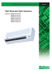
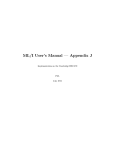
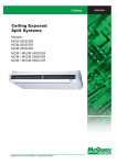
1
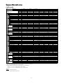
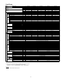
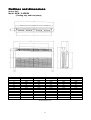
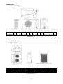
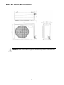
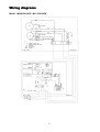
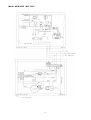
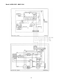
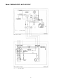
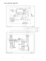
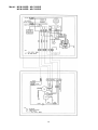
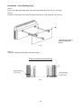
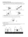
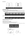
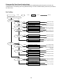
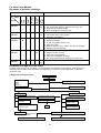
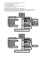
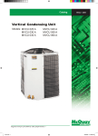
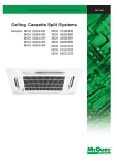
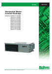
Catalog 2110B Ceiling And Floor Convertible Fan Coil Unit Models: MCM 020D/DR MCM 025D/DR MCM 030D/DR MCM 040D/DR MCM 050D/DR Contents Special Features ................................................................................................................ 2 Specifications ................................................................................................................ 3 - 4 Outlines and Dimensions............................................................................................... 5 - 7 Wiring Diagrams ......................................................................................................... 8 - 16 Installation ................................................................................................................ 17 - 25 Servicing And Maintenance ....................................................................................... 26 - 27 Trouble Shooting ...................................................................................................... 28 - 33 Note : Installation and maintenance are to be performed only by qualified personnel who are familiar with local codes and regulations, and experienced with this type of equipment. Caution: Sharp edges and coil surfaces are a potential injury hazard. Avoid contact with them. Warning : Moving machinery and electrical power hazard. May cause severe personal injury or death. Disconnect and lock off power before servicing equipment. "McQuay" is a registered trademark of McQuay International. All rights reserved throughout the world. 1998 McQuay International "Bulletin illustrations cover the general appearance of McQuay International products at the time of publication and we reserve the right to make changes in design and construction at any time without notice." 1 Special features Ultra Slim New Stylish Design Profile This unit is contemporary in design and match even the most up to date interior decor. The slim, round profile and compact design of this unit adds a touch of elegance to every decor. No indoor connection pipe and hanger bracket are visible. Ceiling And Floor Convertible With Space Saving Installation This unit is designed for ceiling exposed type and floor exposed type with a very economical and space saving installation. No need renovation to wall or ceiling for ceiling exposed and no foundation work is required for floor exposed installation. This easy to install and ready to operate unit ensure rapid and low installation cost. Strong And Robust The unit is built from strong casing material and robust parts to ensure long lasting reliable service. The drain pan is made from the POLYSTYRENE with a plastic coating on the surface to ensure no leaking and no condensation occur. Friendly Serviceability The air filter, electrical parts, fan and fan motor assembly can all be inspected and replace from bottom of the unit by simply removing the newly designed press in, pull out air intake grille. The POLYSTYRENE drain pan and the heat exchanger coils can remove from the unit easily by remove the bottom panel. Microcomputer Remote Controller The incorporated microprocessor give more accurate control and with the following extra features: • Fan motor speed can be set at high/medium/low and automatic. • Timer on/off - the unit can be pre-set to on and off automatically. • Electronic thermostat - room temperature is precisely controlled resulting in energy saving and increase comfort. • Sleep mode automatically increase set temperature since room temperature is lower at night thus achieving healthy sleep. Wireless Remote Controller The compact wireless remote controller makes it possible to operate the air conditioner anywhere within the room. Auto Or Manual Control On Vertical Airflow Direction With auto control, the louver will automatically swing up and down to create an excellent air distribution. You can select your desired horizontal air flow direction by adjusting the vertical grille. 2 Specifications Cooling only MODEL INDOOR UNIT OUTDOOR UNIT COIL FIN INDOOR UNIT COMP. MCM050D MMC050B MLC050C 12,600 12,600 14,654 14,654 50,000 50,000 1,120 / 31.8 4 POLES X 145W 240 1.04 S.B.C 740 / 21.0 4 POLES X 95W 132 0.58 S.I.G.C 1,120 / 31.8 4 POLES X 145W 240 1.04 S.I.G.C 9.52 / 3/8 0.35 / 0.014 ALUMINIUM ALUMINIUM (HYDROPHILIC TYPE) 0.11 / 0.0043 4 4 3 12 12 12 0.36 / 3.95 0.36 / 3.95 0.24 / 2.58 249 / 9.80 249 / 9.80 249 / 9.80 1,714 / 67.40 1,714 / 67.40 1,214 / 47.80 670 / 26.30 670 / 26.30 670 / 26.30 70 70 45 MICROCOMPUTER CONTROLLED THERMOSTAT AUTOMATIC LOUVER (UP&DOWN) & MANUAL LOUVER (BOTTOM) LCD WIRELESS MICROCOMPUTER REMOTE CONTROL 19.05 / 3/4 WASHABLE SARAN NET (OPTIONAL IONIZER FILTER) 301 / 11.9 345 / 13.6 345 / 13.6 1,311 / 51.6 1,816 / 71.4 1,361 / 53.5 760 / 29.9 760 / 29.9 760 / 29.9 220 - 240 / 1 / 50 380 - 420 / 3 / 50 ROTARY HERMETIC RECIPROCATING HERMETIC 35 45 45 45 62 47 59 85 6.3 / 5.8 8.2 / 8.3 9.9 12.5 13.9 2,073 2,761 2,809 3,780 3,486 4,500 4,943 3 12 0.19 / 2.06 214 / 8.42 1,214 / 47.80 670 / 26.30 43 3 12 0.19 / 2.06 214 / 8.42 1,214 / 47.80 670 / 26.30 43 OVERLOAD PROTECTION OVERLOAD PROTECTION AND MANUAL RESET HIGH/LOW PRESSURE SWITCH PROPELLER / DIRECT GLASS REINFORCED ACRYL STYRENE RESIN 355.6 / 14.0 355.6 / 14.0 609.6 / 24.0 2 x 0.28 2 x 0.28 1.09 2 x 30 2 x 30 145 124 124 241 S.B.C 9.52 / 3/8 420.0 / 16.5 0.56 55 133 S.B.C S.I.G.C 0.35 / 0.014 0.36 / 0.014 AVERAGE 609.6 / 24.0 1.09 145 241 3 14 0.77 / 8.29 1094 / 43.07 960 / 37.79 437 / 17.20 112 2 16 0.87 / 9.33 850 / 33.46 1029 / 40.53 400 / 15.75 105 9.52 / 3/8 19.05 / 3/4 1,000 / 39.37 1,265 / 49.80 1,200 / 47.24 1,084 / 42.68 560 / 22.05 641 / 25.24 1,000 / 39.37 1,200 / 47.24 560 / 22.05 ALUMINIUM 0.127 / 0.005 3 2 14 14 0.55 / 6.00 0.77 / 8.29 991 / 39.00 1094 / 43.07 772 / 30.40 960 / 37.79 400 / 15.75 437 / 17.20 90 95 GALVANISED MILD STEEL 0.8 / 0.031 POLYESTER POWDER FLARE VALVE 2 14 0.51 / 5.53 646 / 25.40 840 / 33.10 330 / 13.00 57 406.4 / 16.0 2 x 0.78 2 x 80 341 0.35 / 0.014 ALUMINIUM (SLIT TYPE) 58 9.52 / 3/8 15.88 / 5/8 6.35 / 1/4 15.88 / 5/8 710 / 27.95 957 / 37.68 461 / 18.15 1,183 / 46.57 904 / 35.59 588 / 23.15 1) ALL SPECIFICATIONS ARE SUBJECTED TO CHANGE BY THE MANUFACTURER WITHOUT PRIOR NOTICE. 2) ALL UNITS ARE BEING TESTED AND COMPLY TO ARI 210/240-89 3) NOMINAL COOLING AND HEATING CAPACITY ARE BASED ON THE CONDITIONS BELOW : a) COOLING - 26.7°C DB / 19.4°C WB INDOOR AND 35°C DB OUTDOOR b) HEATING - 21.1°C DB / 15.6°C WB INDOOR AND 8.3°C DB / 6.1°C WB OUTDOOR Abbreviation S.B.C. S.I.G.C - MCM040D MMC040B MLC040C 10,080 10,080 11,723 11,723 40,000 40,000 220 - 240 / 1 / 50 R22 / CAPILLARY TUBE IN INDOOR 680 / 19.3 4 POLES X 95W 130 0.58 S.B.C FIN TUBE MCM030D MMC030A 7,560 8,792 30,000 R22 / CAPILLARY TUBE IN OUTDOOR FAN COIL OUTDOOR UNIT PIPE MCM025D MLC025B 6,300 7,327 25,000 590 / 16.7 4 POLES X 45W 96 0.40 TUBE FAN NOMINAL kcal/h COOLING W CAPACITY Btu/h POWER SOURCE V/Ph/Hz REFRIGERANT / CONTROL AIR FLOW cfm/cmm FAN MOTOR RATED INPUT POWER W RATED RUNNING CURRENT A MATERIAL DIAMETER mm/in THICKNESS mm/in MATERIAL THICKNESS mm/in ROW FIN PER INCH FACE AREA m2/ft2 HEIGHT mm/in DIMENSION WIDTH mm/in DEPTH mm/in WEIGHT kg ROOM TEMPERATURE CONTROL AIR DISCHARGE OPERATION CONDENSATE DRAIN SIZE mm/in AIR FILTER PACKING HEIGHT mm/in DIMENSION WIDTH mm/in DEPTH mm/in POWER SOURCE V/Ph/Hz COMPRESSOR TYPE CAPACITOR µF LOCK ROTOR AMP. A RATED RUNNING CURRENT A RATED INPUT POWER W PROTECTION DEVICE FAN TYPE / DRIVE BLADE MATERIAL DIAMETER mm/in RATED RUNNING CURRENT A RATED OUTPUT POWER W RATED INPUT POWER W MATERIAL DIAMETER mm/in THICKNESS mm/in MATERIAL THICKNESS mm/in ROW FIN PER INCH FACE AREA m2/ft2 HEIGHT mm/in DIMENSION WIDTH mm/in DEPTH mm/in WEIGHT kg MATERIAL CASING THICKNESS mm/in FINISHING TYPE SIZE LIQUID mm/in GAS mm/in PACKING HEIGHT mm/in DIMENSION WIDTH mm/in DEPTH mm/in MCM020D MLC020B 5,040 5,862 20,000 SEAMLESS BARE COPPER SEAMLESS INNER GROOVE COPPER 3 1,265 / 49.80 1,084 / 42.68 641 / 25.24 2 16 0.87 / 9.33 850 / 33.46 1029 / 40.53 400 / 15.75 100 Heat Pump MODEL INDOOR UNIT OUTDOOR UNIT COIL TUBE COIL FIN PIPE OUTDOOR UNIT FAN COMP INDOOR UNIT FIN TUBE FAN NOMINAL COOLING CAPACITY NOMINAL HEATING CAPACITY POWER SOURCE REFRIGERANT / CONTROL AIR FLOW FAN MOTOR RATED INPUT POWER RATED RUNNING CURRENT MATERIAL DIAMETER THICKNESS MATERIAL THICKNESS ROW FIN PER INCH FACE AREA HEIGHT DIMENSION WIDTH DEPTH WEIGHT ROOM TEMPERATURE CONTROL AIR DISCHARGE OPERATION CONDENSATE DRAIN SIZE AIR FILTER PACKING HEIGHT DIMENSION WIDTH DEPTH POWER SOURCE COMPRESSOR TYPE CAPACITOR LOCK ROTOR AMP. RATED RUNNING CURRENT (COOLING) RATED RUNNING CURRENT (HEATING) RATED INPUT POWER (COOLING) RATED INPUT POWER (HEATING) PROTECTION DEVICE FAN TYPE / DRIVE BLADE MATERIAL DIAMETER RATED RUNNING CURRENT RATED OUTPUT POWER RATED INPUT POWER MATERIAL DIAMETER THICKNESS MATERIAL THICKNESS ROW FIN PER INCH FACE AREA HEIGHT DIMENSION WIDTH DEPTH WEIGHT MATERIAL CASING THICKNESS FINISHING TYPE SIZE LIQUID GAS PACKING HEIGHT DIMENSION WIDTH DEPTH kcal/h W Btu/h kcal/h W Btu/h V/Ph/Hz MCM020DR MLC020BR 5,040 5,862 20,000 5,292 6,155 21,000 MCM025DR MLC025BR 6,048 7,034 24,000 6,300 7,327 25,000 R22 / CAPILLARY TUBE IN OUTDOOR cfm/cmm W A 590 / 16.7 4 POLES X 45W 96 0.40 MCM040DR MLC040CR 10,080 11,723 40,000 10,332 12,016 41,000 MCM050DR MLC050CR 12,096 14,068 48,000 12,096 14,068 48,000 R22 / CAPILLARY TUBE & TXV IN OUTDOOR 680 / 19.3 4 POLES X 95W 130 0.58 S.B.C mm/in mm/in 740 / 21.0 4 POLES X 95W 132 0.58 S.I.G.C 9.52 / 3/8 0.35 / 0.014 1,120 / 31.8 4 POLES X 145W 240 1.04 S.B.C 1,120 / 31.8 4 POLES X 145W 240 1.04 S.I.G.C ALUMINIUM mm/in m 2/ft2 mm/in mm/in mm/in kg mm/in mm/in mm/in mm/in V/Ph/Hz µF A A A W W ALUMINIUM (HYDROPHILIC TYPE) 0.11 / 0.0043 3 3 3 4 4 12 12 12 12 12 0.19 / 2.06 0.19 / 2.06 0.24 / 2.58 0.36 3.95 0.36 3.95 214 / 8.42 214 / 8.42 249 / 9.80 249 / 9.80 249 / 9.80 1,214 / 47.80 1,214 / 47.80 1,214 / 47.80 1,714 / 67.40 1,714 / 67.40 670 / 26.30 670 / 26.30 670 / 26.30 670 / 26.30 670 / 26.30 43 43 45 70 70 MICROCOMPUTER CONTROLLED THERMOSTAT AUTOMATIC LOUVER (UP&DOWN) & MANUAL LOUVER (BOTTOM) LCD WIRELESS MICROCOMPUTER REMOTE CONTROL 19.05 / 3/4 WASHABLE SARAN NET (OPTIONAL IONIZER FILTER) 301 / 11.9 345 / 13.6 345 / 13.6 1,311 / 51.6 1,816 / 71.4 1,361 / 53.5 760 / 29.9 760 / 29.9 760 / 29.9 220 - 240 / 1 / 50 380 - 420 / 3 / 50 ROTARY HERMETIC RECIPROCATING HERMETIC 35 45 45 49.0 56.5 78.0 45.0 62.0 11.0 13.3 13.4 6.0 7.6 9.7 13.6 12.9 5.4 7.0 2,040 2,667 2,643 3,431 4,480 2,140 2,757 2,562 2,921 3,902 OVERLOAD PROTECTION 420.0 / 16.5 0.56 55 133 mm/in A W W mm/in mm/in OVERLOAD PROTECTION AND MANUAL RESET HIGH/LOW PRESSURE SWITCH PROPELLER / DIRECT GLASS REINFORCED ACRYL STYRENE RESIN 609.6 / 24.0 1.09 1.09 145 145 241 241 S.B.C 9.52 / 3/8 S.B.C S.I.G.C 0.35 / 0.014 0.36 / 0.014 AVERAGE 0.35 / 0.014 ALUMINIUM (SLIT TYPE) m 2/ft2 mm/in mm/in mm/in kg 0.35 / 0.014 0.35 / 0.014 ALUMINIUM 2 14 0.51 / 5.53 646 / 25.40 840 / 33.10 330 / 13.00 57 58 mm/in mm/in mm/in mm/in mm/in mm/in 2.7 460 635 0.127 / 0.005 mm/in 6.35 / 1/4 15.88 / 5/8 710 / 27.95 957 / 37.68 461 / 18.15 1) ALL SPECIFICATIONS ARE SUBJECTED TO CHANGE BY THE MANUFACTURER WITHOUT PRIOR NOTICE. 2) ALL UNITS ARE BEING TESTED AND COMPLY TO ARI 210/240-89 3) NOMINAL COOLING AND HEATING CAPACITY ARE BASED ON THE CONDITIONS BELOW : a) COOLING - 26.7°C DB / 19.4°C WB INDOOR AND 35°C DB OUTDOOR b) HEATING - 21.1°C DB / 15.6°C WB INDOOR AND 8.3°C DB / 6.1°C WB OUTDOOR Abbreviation S.B.C. S.I.G.C - MCM030DR MLC030CR 7,560 8,792 30,000 8,064 9,379 32,000 220 - 240 / 1 / 50 SEAMLESS BARE COPPER SEAMLESS INNER GROOVE COPPER 4 98 GALVANISED MILD STEEL 0.8 / 0.031 POLYESTER POWDER FLARE VALVE 9.52 / 3/8 15.88 / 5/8 2 16 0.87 / 9.33 850 / 33.46 1029 / 40.53 400 / 15.75 110 115 9.52 / 3/8 19.05 / 3/4 1,000 / 39.37 1,200 / 47.24 560 / 22.05 Outlines and dimensions Indoor Unit Model: MCM - D SERIES (Cooling only and heat pump) MODEL A B C D E F G H I J K L M MCM 020D/DR 1174 75 1082 68 58 156 1214 57 670 216 319 879 517 MCM 025D/DR 1174 75 1082 68 58 156 1214 57 670 216 319 879 517 MCM 030D/DR 1174 75 1082 68 93 156 1214 57 670 216 319 879 517 All dimensions in mm 5 MCM 040D/DR 1674 75 1582 68 93 156 1714 57 670 216 319 1379 517 MCM 050D/DR 1674 75 1582 68 93 156 1714 57 670 216 319 1379 517 Outdoor unit Model: MLC - B SERIES MODEL A MLC 020B / BR 840 MLC 025B / BR 840 B 646 646 C 330 330 D 297 297 E 309 309 F 626 626 G 46 46 H 90 90 J 64 64 K 177 177 L 106 106 M 408 408 N 378 378 P 124 124 Q R 492 78.5 492 78.5 All dimensions in mm Model: MMC SERIES MODEL MMC 030A MMC 040B MMC 050B A 772 960 960 B 991 1095 1095 C 400 437 437 D 414 470 470 E 492 622 622 F 280 338 338 G 25 20 20 All dimensions in mm 6 H 284 305 305 I 441 492 492 J 240 277 277 K 127 106 106 L 518 748 748 M 127 106 106 Model : MLC 040/050C, MLC 030/040/050CR Caution Sharp edges and coil surfaces are potential locations which may cause injury hazards. Avoid from being in contact with these places. 7 Wiring diagrams Model : MCM 020/025D - MLC 020/025B 8 Model: MCM 030D - MLC 030C 9 Model: MCM 030D - MMC 030A 10 Model : MCM 040D/050D - MLC 040C/050C 11 Model: MCM 040D - MMC 040B 12 Model: MCM 050D - MMC 050B 13 Model: MCM 020DR - MLC 020BR MCM 025DR - MLC 025BR 14 Model: MCM 030DR - MLC 030CR 15 Model: MCM 040DR - MLC 040CR MCM 050DR - MLC 050CR 16 Installation Caution Sharp edges and coil surface are potential injury hazard. Avoid from contact with them. (1) INSTALLATION OF INDOOR UNIT Preliminary Site Survey • Electrical supply and installation shall conform to the local authority (eg. National Electrical Board). • Voltage supply fluctuation must not exceed ±10% of the rated voltage. Electricity supply lines must be independent of welding transformers which can cause high supply fluctuation. • Ensure that the installation location is convenient for wiring and piping. Standard Mounting Ensure that the overhead supports are strong enough to hold the weight of the unit. Position the hanger rods (wall mounting bracket for floor standing), and check for its alignment with the unit as shown in Figure A. Also, check that the hangers are secured and the base of the fan coil unit is leveled in both horizontal directions, taking into account the gradient for drainage flow as recommended in Figure B. Model MCM 020D/DR MCM025D/DR MCM030D/DR MCM040D/DR MCM050D/DR A 1214 1214 1214 1714 1714 B 666 666 666 666 666 C 273 273 273 273 273 D 130 130 130 130 130 F 1160 1160 1560 1560 1560 G 27 27 27 27 27 H 77 77 77 77 77 I 745 745 745 1235 1235 J 25 25 25 25 25 K 209 209 209 331 331 L 486 486 486 486 486 M 108 108 108 108 108 N 360 360 360 600 600 O 770 770 770 1270 1270 P 136 136 136 136 136 Q 373 373 373 373 373 R 222 222 222 310 310 Note : Dimensions in mm Figure A Figure B 17 Please ensure that the following steps are taken: • Cheek the gradient for drainage flow as recommended in Figure B. • Provide clearance for easy servicing and optimal air flow as shown in Figure B. • The indoor unit must be installed such that there is no short circuit of the cool discharge air with the warm return air. • Do not install the indoor unit where there is direct sunlight shining on the unit. The location should be suitable for piping and drainage installation. The unit must be a large distance away from the door. Semi-Enclose Mounting • In case the units is to be half recessed into false ceiling, please check the unit is well align. Figure C • Provide the installation space as shown in Fig. D. Figure D 18 Installation - Ceiling Exposed Type STEP 1 Remove air intake grille, side panel, side close-up and hanger bracket from the unit; see Fig E. Figure E STEP 2 Position the hanger rods as per Fig B and install the hanger bracket; see Fig F. Figure F STEP 3 Hanger up the unit and tighten the bolt, after completed the piping and drain pipe; install back the grille and panel Fig. G. Figure G 19 Installation - Floor Standing Type STEP 1 Remove air intake grille, side panel, side close-up and side panel from the unit; see Fig E. STEP 2 Position the floor support and wall mounting bracket as per Fig B. install the unit; see Fig 1. * Wall mounting bracket will be supplied upon request. Fig I STEP 3 Two type of piping and drain pipe connection as Fig J. Piping and drain pipe installation Fig J 20 (2) Installation Of Outdoor Unit As condensing temperature rises, evaporating temperature rises and cooling capacity drops. In order to achieve maximum cooling capacity, the location selected for outdoor unit should fulfil the following requirements:- • • • • • • Install the condensing (outdoor) unit in away such that hot air distributed by the outdoor condensing unit cannot be drawn in again (as in the case of short circuit of hot discharge air). Allow sufficient space for maintenance around the unit. Ensure that there are no obstruction of air flow into or out of the unit. Remove obstacles which block air intake or discharge. The location must be well ventilated, so that the unit can draw in and distribute plenty of air thus lowering the condensing temperature. A place capable of bearing the weight of the outdoor unit and isolating noise and vibration. A place protected from direct sunlight. Otherwise use an awning for protection, if necessary. The location must not be susceptible to dust or oil mist. Installation Clearance • Outdoor units must be installed such that there is no short circuit of the hot discharge air or obstruction to smooth air flow. Select the coolest possible place where intake air should not be hotter than the outside temperature (max. 45°C). MLC SERIES Minimum Distance Series I Series II A 150mm 300mm B 1000mm 1000mm 21 C 150mm 300mm D 500mm 500mm MMC SERIES ALL MODELS Minimum Distance A 300mm B 1000mm C 300mm (3) Refrigerant Piping Maximum Pipe Length And Maximum Number Of Bends • When the pipe length becomes too long, both the capacity and reliability drop. As the number of bends increases, system piping resistance to the refrigerant flow increases, thus lowering the cooling capacity, and as the result the MODEL DATA Max. Length, L Max. Elevation, H Max. No. of bends 020 025 030 040 050 15m 8m 10 15m 8m 10 20m 10m 10 20m 10m 10 20m 10m 10 compressor may become defective. Always choose the shortest path and follow the recommendation as tabulated below: MODEL Liquid (mm/in) Suction (mm/in) 020 6.35(1/4) 15.88(5/8) 025 9.52(3/8) 15.88 (5/8) 030 9.52(3/8) 15.88 (5/8) 040 9.52(3/8) 19.05 (3/4) 050 9.52(3/8) 19.05 (3/4) Piping Sizes (Flare Connection Type) • Piping sizes are as follows: Piping Connection To The Units • • • Align the center of the piping and sufficiently tighten the flare nut with fingers. Finally, tighten the flare nut with torque wrench until the wrench clicks. When tightening the flare nut with torque wrench, ensure the direction for tightening follows the arrow on the wrench. PIPE SIZE (mm/in) 6.35(1/4) 9.53(3/8) 12.7(1/2) 15.88(5/8) 9.05(3/4) TORQUE (Nm) 18 42 55 65 78 22 (4) Wiring Electrical Connections • Wiring regulations on wire diameters differ from country to country. Please refer to your LOCAL ELECTRICAL CODES for field wiring rules. Be sure that installation comply with such rules and regulations. General Precautions • Ensure that the rated voltage of the unit corresponds to the name plate before carrying out proper wiring according to the wiring diagram. • Provide a power outlet to be used exclusively for each unit. A power supply disconnect and a circuit breaker for over-current protection should be provided in the exclusive line. • The unit must be GROUNDED to prevent possible hazards due to insulation failures. • All wiring must be firmly connected. • All wiring must not touch the hot refrigerant piping, compressor or any moving parts of fan motors. (5) Vacuuming and Charging • The precharged outdoor unit does not need any vacuuming or charging. However once it is connected, the connecting pipe line and the indoor need to be vacuumed before releasing the R22 from the outdoor unit. 1) Open the service port core cap. 2) Connect pressure gauge to the service port. 3) Connect the line to vacuum pump. Open the charging manifold valve and turn the pump on. (evacuation time varies by the capacity of the pump but averagely in 1 hour). Diagram 1 4) After evacuation, unscrew the spindle (diagram 2B) for the gas to run to indoor unit. Diagram 2 23 (6) Additional Charge • The refrigerant gas has already charged into the outdoor unit. For the piping length of 5m. Additional refrigerant charge after vacuuming is not necessary. • When the piping length is more than 5m, please use the table below (unit in gram). MODEL 020 025 030 040 050 7m 30 76 100 100 100 10m 75 190 250 250 250 15m 150 380 500 500 500 (7) Overall Checking • Ensure the following, in particular: 1) The unit is mounted solidly and rigid in position. 2) Piping and connections are leak proof after charging. 3) Proper wiring has been done. • Drainage check - pour some water into drain pan. • Test run 1) Conduct a test run after water drainage test and gas leakage test. 2) Watch out for the following: a) Is the electric plug firmly inserted into the socket? b) Is there any abnormal sound from unit? c) Is there any abnormal vibrations with regard to unit itself or piping? d) Is there smooth drainage of water? • Cheek that: 1) Outdoor fan is running, with warm air blowing off the outdoor unit (cooling cycle). 2) Indoor blower is running and discharge cool air (cooling cycle). 3) Suction (low side) pressure as recommended is before this. 4) The remote controller incorporate a 3 minute delay in there circuit. Thus, it requires about 3 minutes before the outdoor unit can start up. 24 20m 750 750 750 (8) Standard Operating Condition Cooling Only Unit Temperature minimum indoor temperature maximum indoor temperature minimum outdoor temperature maximum- outdoor temperature Ts °C 19.4 26.7 19.4 46.0 Th °C 13.9 19.4 13.9 24.0 Heat Pump Unit Temperature minimum indoor temperature maximum indoor temperature minimum outdoor temperature maximum- outdoor temperature Ts °C 10.0 26.7 -8.0 24 Ts : Dry bulb temperature Th : Wet bulb temperature 25 Th °C -9.0 18 Servicing and maintenance Warning Disconnect from Main Supply before Servicing the air conditioner The unit is designed to give a long life operation with minimum maintenance required. However, it should be regularly checked and the following items should be given due attention. Components Air Filters Maintenance Procedure 1. Clean with a vacuum cleaner, or by tapping lightly and then washing in lukewarm water (below 40°C) With neutral soap. Recommended Schedule Every 2 weeks. More frequently if required. 2. Rinse well to dry before re-installing. 3. Note Never use petrol, thinner, benzene or any other chemicals. Indoor Unit 1. Clean away dirt or dust on grille or panel by wiping with a soft cloth soaked in lukewarm (or cold) water or neutral detergent solution. Every 2 weeks. More frequently if required. 2. Note: Never use petrol, thinner, benzene or any other volatile chemicals, which may cause plastic surface to deform. Condensate Drain 1. Check and clean. Every 3 months. Indoor Fan 1. Check for unusual noise. As necessary. Indoor/Outdoor Coil 1. Check and remove dirt which are clogged between fins. Every month. Pan & Pipe 2. Check and remove obstacles which hinder air flow in and out of indoor/outdoor unit. Every month. 1. Check voltage, current and wiring. Every 2 months. 2. Check faulty contacts caused by loose connections, foreign matters, etc. Every 2 months. Compressor 1. No maintenance needed if refrigerant circuit remains sealed. However, check for refrigerant leak at joints & fittings. Every 6 months. Compressor Lubrication 1. Oil is factory charged. Not necessary to add oil if circuit remains sealed. No maintenance required. Fan Motors Lubrication 1. All motors pre-lubricated and sealed at factory. No maintenance required. Electrical PRE-START UP MAINTENANCE (AFTER EXTENDED SHUTDOWN) - Inspect thoroughly and clean indoor and outdoor units. Clean or replace air filters. Clean condensate drain line. Clean clogged indoor and outdoor coils. Check fan imbalance before operation. Tighten all wiring connections and panels. Check for refrigerant leakage. 26 The design of the MLC outdoor series allows servicing to be carried out readily and easily. The removal of the top side, front and back panel make almost every part accessible. Under normal circumstances, these outdoor units only require a check and cleaning of air intake coil surface once quarterly. However, if a unit is installed in areas subjected to much oil mist and dust, the coils must be regularly cleaned by qualified Air Conditioner Service Technicians to ensure sufficient heat exchange and proper operation. Otherwise, the systems life span may be shortened. CAUTION! Do not charge OXYGEN, ACETYLENE OR OTHER FLAMMABLE and poisonous gases into the unit when performing a leakage test or an air tight test. These gases could cause severe explosion and damage if expose the high temperature and pressure. It is recommended that only nitrogen or refrigerant be charged when performing the leakage or airtight test. 27 Troubleshooting When any air-conditioner malfunction is noted, immediately switch off the power supply to the unit, and contact the local dealer, if necessary. Some simple troubleshooting tips are given below : FAULT 1. Fan does not work 3 minutes after starting CAUSE • Protection against the frequent starting. Wait 3 or 4 minutes. • • • • 3. The air conditioning unit does not • blow sufficiently • • • 4. The remote control light is deficient • • • 5. Air discharge flow has a bad odor • 2. The air conditioning unit does not work 6. Condensation on the air grille of indoor unit 7. The water flow of air conditioning unit 8. The air conditioning unit are noisy • • • • • Power failure or you must be replaced the fuse. The power plug is disconnected. Possibility of making a programming error in the controller. If the fault persist after these verifications, contact your installer. The air filter is dirty. The doors or windows are open. The air entrance and exit are clogged. The regulate temperature is not high enough. The batteries are discharge. The batteries are not correctly inserted. The assembly is not good. This odor can be caused by cigarette smoke particles, perfume, sweat, which stick to the coil. Check if there is any moisture on the walls, garment, other. Check the drain pan. This is due to air humidity after a long time of operation. The unit has a lower temperature point, increase the point and operate at high speed. Check the condensate evacuation. • “Air flow noise” : refrigerant fluid admission in evaporator. 28 Diagnosis By Flow Chart (Cooling Only) The following chart are efficient checking procedures for troubleshooting when these fan-coil units, are coupled with the condensing units using standard wiring. For dual circuited models, perform the procedures for each circuit. No Cooling : Check : Faulty : Cause Remedy No Cooling ( Compresor Does Not Start ) Evaporator Fan Motor Stop Unit Power Supply Running Faulty Single-Phase Fuse For Operation Circuit Blown Overcurrent Relay For Evaporator Fan Tripped Evaporator Fan Contactor No Voltage or Low Voltage Components Shorted Connections Loose High Volage or Low Voltage Single-Phase Faulty Coil Burned Contact Faulty Faulty Fan Motor Defective Operation Switch Condenser Fan Motor Get the Riht voltage Repair the Power Line Repair or Replace The Components Tighten The Connections Get The Right Voltage Check The Power SupplyTo The Motor : Repair When Necessary Change The Contactor Repair The Contacts Repair Or Change The Motor Repair Or Replace The Switch Stop Overcurrent Relay For Condenser Fan Tripped High Voltage or Low Voltage Single-Phase Running Condenser Fan Contactor Faulty Coil Burnt Contact Faulty Fan Motor Faulty Other Electrical Component Faulty Compressor Contactor Faulty Coil Burnt Contact Faulty Open Compressor Windings Incorrect Wiring 29 Get The Right Voltage Check The Power Supply To The Motor : Repair Connections When Necessary Change The Contactor Change The Contacts Repair or Change The Motor Repair or Change If Necessary Change The Contactor Repair The Contacts Change The Compressor Correct The Wiring Insufficient Cooling Insufficient Cooling Compressor Cycling Cycling On Dual Pressure Switch Tripping High Discharge Pressure or Low Suction Pressure See "High Discharge Pressure" or "Low Suction Pressure" Clogged Capillary or Pressure Switch Repair Clogging and Replace The Switch If Required Switch Faulty Running Overcurrent Relay For Compressor Tripping High Voltage or Low Voltage Single-Phase High Discharge Pressure And High Suction Pressure Loose Connections Discharge Gas Thermostat or Internal Thermostat Tripping High Discharge Pressure And Low Suction Pressure Refrigerant Short Charge or Refrigerant Leakage High Suction Pressure High Discharge Pressure or Low Suction Pressure Repair or Change If Necessary Get The Right Voltage Check The Power Line To The Compressor : Repair When Necessary See "High Discharge Pressure" or "High Suction Pressure" Tighten The Connections See "High Discharge Pressure" or "Low Suction Pressure" Add Refrigerant. Repair Leakage If Detected. See "High Suction Pressure" See "High Discharge Pressure" or "Low Suction Pressure" High Discharge Pressure High Discharge Pressure Restricted Condenser Air Flow Clogged Condenser Coil Low Fan Speed Condenser Air Inlet Temperature High Malfunction Of Fan Cycling System Circulating Air Flow Overcharged Refrigerant Non-Condensable Gas Restricted Liquid Line High Suction Pressure Clean The Condenser Check The Voltage And Get The Right Voltage Check The System And Repair If Required Secure Space For Required Air Flow Purge The Refrigerant Purge The Gas Remove The Restriction See "High Suction Pressure" Low Discharge Pressure Low Discharge Pressure Condenser Air Flow Excessive Malfunction Of Fan Cycling System Low Refrigerant Charge Low Ambient Temperature 30 Check The System And Repair The Components If Required Add Refrigerant See The Unit Working Range High Suction Pressure High Suction Pressure Low Evaporator Air Inlet Temperature Excessive Fresh Air Intake Reduce The Fresh Air Intake Insufficient Duct Insulation Reinforce The Duct Insulation Defective Compressor Valve Overcharged Refrigerant Change Or Repair The Compressor Purge The Refrigerant Low Suction Pressure Low Suction Pressure Evaporator Air Flow Restricted Evaporator Air Inlet Temperature Clogged Air Filter Low Clean The Air Filter Restricted Duct Remove The Restriction Low Fan Speed Adjust The Fan Speed Short Cycling Faulty Thermostat Restricted Liquid LIne And Suction Line Low Refrigerant Charge Low Discharge Pressure Remove Obstacles To Air Circulation Repair Or Replace If Necessary Remove The Restriction Add Refrigerant See "Low Discharge Pressure" Noisy Operation Noisy Operation Compressor Noisy Shipping Bolt(s) Noisy Unremoved Shipping Bolt(s) Overcharged Refrigerant Liquid Refrigerant Backing Up Low Suction Pressure Worn Compressor Parts Evaporator Fan Liquid Line Noisy Knocking Runner Noisy Strainer Whistling Worn Bearing Remove The Bolt(s) Purge The Refrigerant See "Low Suction Pressure" Replace Or Repair The Compressor Fix The Runner Or Casing Properly Change The Bearing Partially Clogged Clean The Dryer Refrigerant Short Charge Add Refrigerant Loose Fixed Screws Inadequate Duct Work 31 Tighten All Fixed Screws Check Flexible Ducts For Heat Pump Models By means of pressure readings : = = High Side Low Side High Side Low Side High Side Low Side Too High PROBABLE CAUSE A Little High Normal Circuit Too Low Data A Little Low PRESSURE 1. Overcharged with refrigerant. 2. Non-condensable gases in refrigerant circuit (e.g. oil). 3. Obstructed air-intake/discharge. 4. Short circuiting of hot air outdoor unit. 1. Poor compression/no compression (compressor defective.) 2. Check valve stick in open position. 3. Reversing valve leaking. 1. Undercharged with refrigerant. 2. Refrigerant leakage. 3. Air filter clogged/dirty (indoor unit). 4. Indoor fan locked. 5. Defective defrost control, outdoor coil freeze up (heating). 6. Outdoor fan locked (heating). 1. Outdoor fan blocked (cooling). 2. Outdoor coil dirty (cooling). 3. Indoor fan locked (heating). 4. Indoor filter clogged/dirty (heating). 5. Non-condensable gases in refrigerant circuit (e.g. air) 1. Air intake temperature of indoor unit too high. = = = = = High Side Low Side = = High Side Low Side = By Means Of Diagnosis Flow Chart Generally, there are two kind of problems, i.e. starting failure and insufficient cooling/heating. "Starting Failure" is caused by electrical defect while "Insufficient Cooling/Heating" is caused by improper application or defects in refrigerant circuit. i) Diagnosis of Electric Circuit No Cooling / Heating Unit fail to start Check power supply - voltage - phase - frequency Check settings of remote control box Check power source cord Check circuit breake & fuse Fan fails to start Compressor fails to start Fan Motor Capacitor defective Thermostat setting too high Loose Connections, Contactors Protection Device Actuated Irregular motor resistance (Ω) & insulation (MΩ) Voltage supply not within range Loose Connections, Improper wiring Compressor Capacitor Defective Reset Check motor resistance ( Ω ) and insulation (MΩ) Replace Fan Motor Regular but fails to start Irregular Compressor locked (to replace compressor) Compressor Motor damaged ( to replace compressor) 32 The most common causes of air conditioner failure to “start" are: a) Voltage not within ±10% of rated voltage. b) Power supply interrupted. c) Control settings improper. d) Air conditioner is disconnected from main power source. e) Fuse blown or circuit breaker off. ii) Diagnosis Of Refrigerant Circuit / Application There might be some cases where the unit starts running but does not perform satisfactory, i.e. insufficient cooling. Judgement could be made by measuring temperature difference of indoor unit's intake and discharge air as well as running current. Insufficient Cooling Unit Starts Check air circulation High heat load Refrigerant circuit Indoor/Outdoor coil dirty (clogged) Air filters dirty Fan Malfunction Leakage Excessive heat source e.g. electric kettle Restriction e.g. at strainer, capillary, filter dryer, etc. Room overcrowded with people Compressor Windows / doors wide open Obstruction at air inlet/outlet of indoor/outdoor unit Less or no compression (Low running current) Satisfactory operation with temperature difference of air intake & discharge of indoor unit 8°C - 13°C Insufficient Heating Unit Starts Check air circulation High heat load Refrigerant circuit Indoor/Outdoor coil dirty (clogged) Leakage Air filters dirty Restriction e.g. at strainer, capillary, filter dryer, etc. Fan Malfunction Compressor Obstruction at air inlet/outlet of indoor/outdoor unit Less or no compression (Low running current) Satisfactory operation with temperature difference of air intake & discharge of indoor unit 14°C - 20°C 33 Windows / doors wide open DOP : 0299 Americas - 13600 Industrial Park Boulevard, P.O. Box 1551, Minneapolis, MINI 55440 USA (612) 553-5330 Asia - Jalan Pengapit 15/19, P.O. Box 7072, 40702 Shah Alam, Selangor Darul Eshan, Malaysia - Tel: 6-03-5594922 - Fax: 6-03-5506980 - Telex: MA 38521 Europe - 42 Cours Jean Jaurès - 17800 Pons - France - Tél: (33) 46 92 33 33 - Télex: 790 536 F - Télecopie: (33) 46 91 38 33