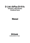
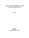
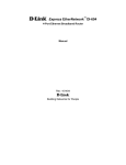
1
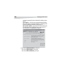
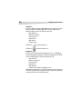
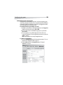
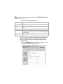
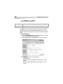
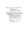
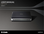
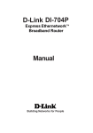
4-Port Cable/DSL Router
Product Name [French]
Product Name [Spanish]
DX-E401
U S E R G U I D E • G U I D E D E L’ U T I L I S AT E U R • G U Í A D E L U S UA R I O
2
Introduction
Dynex 4-Port Cable/DSL Router
Introduction
This router enables you to quickly and easily share a high-speed Internet
connection. The router also incorporates many advanced features traditionally
found in more expensive routers.
After completing the steps outlined in the Installation Guide (included in your
package) you will be able to share a single Internet connection, as well as sharing
information and resources (such as files and printers) on your local network.
The router is compatible with most popular operating systems, including
Windows, Linux, and Macintosh, and can be integrated into an existing network.
This manual provides a quick introduction to broadband router technology,
firewalls, and local area networking. Take a moment to read through this manual
and get acquainted these technologies.
Contents
Introduction..................................................................................................2
Important safety instructions .......................................................................3
Introduction to broadband router technology...............................................3
Features ........................................................................................................4
Product components.....................................................................................6
Setting up the router ....................................................................................7
Configuring the router ................................................................................13
Configuring your computers........................................................................45
Troubleshooting..........................................................................................56
Specifications..............................................................................................57
Warranty.....................................................................................................58
Legal notices...............................................................................................59
Français ............................................................. 61
Español .............................................................. xx
Important safety instructions
3
Important safety instructions
These precautions explain how to safely operate your new router, preventing
injury to you or to others, or damage to the router.
Warning - read this carefully before proceeding.
• Do not open the router or attempt to disassemble or modify it.
• Do not insert fingers or foreign objects into the router.
• Do not expose the router to rain, use it near water or in damp or wet
conditions, or place containers on it that contain liquids which might spill
into openings.
• Follow the Installation Guide and this User Guide carefully. Follow the
correct procedures when setting up the router.
Introduction to broadband router
technology
A router is a device that forwards data packets from a source to a destination using
IP addresses, not MAC addresses. A router forwards data from the Internet to a
particular computer on your network.
The information that makes up the Internet gets moved around using routers.
When you click on a link on a Web page, you send a request to a server to show
you the next page. The information that is sent and received from your computer
is moved from your computer to the server using routers. A router also determines
the best route that your information should follow to ensure that the information
is delivered correctly.
A router controls the amount of data that is sent through your network by
eliminating information that should not be there. This provides security for the
computers connected to your router, because computers from the outside cannot
access or send information directly to any computer on your network. The router
determines which computer the information should be forwarded to, then sends
it. If the information is not intended for any computer on your network, the data is
discarded. This keeps unwanted or harmful information from accessing or
damaging your network.
4
Features
Firewalls
A firewall is a device that is set up between your computer and the Internet which
prevents unauthorized access to or from your network. A firewall can be a
computer using firewall software or a device built specifically to act as a firewall.
In most circumstances, a firewall is used to prevent unauthorized Internet users
from accessing your network.
A firewall analyzes all of the information moving to and from your network and
analyzes each piece of data and checks it against a set of criteria that the
administrator sets. If any data does not meet the criteria, that data is blocked and
discarded. If the data meets the criteria, the data is passed through. This is called
packet filtering.
A firewall can also run specific security functions based on the type of software or
type of port that is being used. For example, a firewall can be configured to work
with an FTP or Telnet server, or with specific UDP or TCP ports to allow certain
software or games to work correctly over the Internet.
LANs and WANs
A Local Area Network (LAN) is several computers connected together within a
small area such as a building or group of buildings. A collection of LANs connected
over a large area is called a Wide Area Network (WAN).
Although there are many ways to connect computers together, the most common
way is Cat-5 cable (UTP or STP twisted pair wire). Wireless networks, which use
radio waves instead of wires, are becoming more common. Each computer must
have a Network Interface Card (NIC), which transfers the data between computers.
A NIC can be a 10 Mbps, 10/100 Mbps, or 10/100/1000 Mbps network card.
Most networks use hardware devices such as hubs or switches to connect
computers. A hub takes any data arriving through each port and forwards the data
to all other ports. A switch is more sophisticated, in that a switch can determine
the destination port for a specific piece of data. A switch minimizes network traffic
overhead and speeds up communication over a network.
Features
BROADBAND MODEM AND IP SHARING
Connects multiple computers to a broadband (cable or DSL) modem to share the
Internet connection.
Features
5
ETHERNET SWITCH
Allows you to quickly and easily share an Internet connection with multiple
computers and devices.
VPN SUPPORTED
Supports multiple and concurrent IPSec and PPTP pass-through sessions, so
multiple users behind the router can access corporate networks through various
VPN clients more securely.
ADVANCED FIREWALL AND PARENTAL CONTROL FEATURES
The Web-based user interface displays a number of advanced network
management features including:
Content filtering—Easily applied content filtering based on MAC address, IP
address, URL, or domain name.
Filter scheduling—Filters can be scheduled to be active on certain days or for a
duration of hours and minutes.
Network Address Translation (NAT)—Allows your networked computers to
share a single IP address and protects you from outside intruders gaining access to
your private network.
DHCP SERVER SUPPORTED
All networked computers can retrieve TCP/IP settings automatically from the
router.
WEB-BASED MANAGEMENT
The router is configurable through any network computer’s Web browser.
ACCESS CONTROL SUPPORTED
Allows you to assign user-specific access rights.
VIRTUAL SERVER SUPPORTED
Allows you to make WWW, FTP, and other services on your LAN accessible to
Internet users.
SPECIAL APPLICATIONS SUPPORTED
Special applications requiring multiple connections are supported, such as
Internet gaming, video conferencing, and Internet telephony. The router can
detect the application type and open a multi-port tunnel for it.
6
Features
DMZ HOST SUPPORTED
Allows a networked computer to be fully exposed to the Internet. This function is
used when the Special Applications feature is insufficient to allow an application
to function correctly.
System requirements for configuration
• Ethernet-based cable or DSL modem
• Computers with Windows, Macintosh, or Linux-based operating systems
with an installed Ethernet adapter
• Internet Explorer Version 6.0 or Netscape Navigator 6.0 and above
Product components
FRONT PANEL
Power indicator
Component
WAN indicator
LAN link/activity
indicators
Function
Power indicator
Turns green when the router is plugged in.
WAN indicator
Turns green when a WAN connection exists.
LAN link/activity
indicators
Turns green when connected to a network
device. Flashes when the corresponding port
is sending or receiving data.
7
Setting up the router
REAR PANEL
WAN port
LAN ports
Component
Reset button
Power
connector
Function
Reset button
Press to restore the router to factory default
settings.
LAN ports 1-4*
The LED glows steadily when a port is
connected to a network device in your local
area network (LAN.)
WAN port*
Connect your cable or DSL modem to this
port.
Power connector
Connect one end of the included power
adapter to the power connector and the
other end to a power outlet.
*All ports (both LAN and WAN) are Auto-MDIX. All ports auto-sense cable types
to accommodate straight-through or crossover cable.
Setting up the router
Network settings
To use the router, you must correctly configure the network settings of your
computers. The default IP address of the router is 192.168.0.1, and the default
subnet mask is 255.255.255.0. These addresses can be changed as needed, but
the default values are used in this manual. If the TCP/IP environment of your
computer has not yet been configured, see “Configuring your computers” on page
45, for information.
We recommend that you configure your computers to obtain TCP/IP settings
automatically from the DHCP server feature of the router.
8
Setting up the router
Since the IP address of the router is 192.168.0.1, the IP address of your computer
must be 192.168.0.X (where “X” is a number between 2 and 254.) Each computer
on your network must have a different IP address within that range. The default
gateway must be 192.168.0.1 (the IP address of the router).
Web-based management utility
The router has a Web-based management utility which is operating system
independent. You can configure your router through a Java Script enabled Web
browser in Windows, Macintosh, Linux, or UNIX-based platforms.
START UP AND LOG IN
To access the Web-based management utility:
1 Open your Web browser and enter the IP address of the router into the
Location (for Netscape) or Address (for Internet Explorer) field, then press
Enter. The default IP address of the router is 192.168.0.1
For example, type 192.168.0.1
After the connection is established, the logon screen opens.
2 To log in as an administrator, enter the user name of admin and leave the
password field blank (default), then click OK. The Web management Home
screen opens.
Setting up the router
9
Using the Setup Wizard
Follow the Wizard step-by-step to quickly configure the router.
To use the Setup Wizard:
1 Start the Web-based management utility. (For more information, see Start
up and Log in on page 8.) The Web Management Home screen opens.
2 Click Run Wizard. The DX-E401 Setup Wizard starts.
3 Click Next. The Set Password screen opens.
4
5
6
7
8
For security purposes, we recommend that you change the default admin
password (that is, no password).
Type your new password, then type it in the Verify Password field a
second time for confirmation.
Click Next to continue. The Choose Time Zone screen opens.
Click on the list to open it, then click the correct time zone for your location.
Click Next. The router will try to auto-detect your Internet connection type.
If you have a Dynamic or PPPoE connection, and the router detects the
connection, the corresponding page opens.
If the Select Internet Connection Type (WAN) screen opens, select the type of
Internet connection that your ISP provides, then click Next.
• Dynamic IP Address—(for example, cable users) Select this option to
obtain an IP address automatically from your ISP. For more information,
10
Setting up the router
see Selecting a dynamic IP address in Windows XP or Windows 2000 on
page 53.
• Static IP Address—Select this option to manually input the IP address
that your ISP assigns to you. For more information, see Assigning a static
IP address in Windows XP and Windows 2000 on page 51.
• PPP over Ethernet (PPPoE)—(for example, DSL users) Select this option
if your ISP requires the use of PPPoE to connect to their services. For
more information, see Configuring PPPoE on page 16.
9 If you selected Dynamic IP Address, go to Step 10.
If you selected Static IP Address, go to Step 13.
If you selected PPP over Ethernet, go to Step 16.
Setting up the router
11
10 If you selected Dynamic IP Address, the Set Dynamic IP Address screen
opens.
Note - This setup should be done on the computer that is registered with your
ISP.
11 If your ISP requires you to enter a specific host name or specific MAC
address, enter it here. Click Clone MAC Address to copy the MAC address of
your Ethernet adapter to the MAC address fields (you can also type it in
manually).
12 Go to step 18.
12
Setting up the router
13 If you selected Static IP Address, the Set Static IP Address screen opens.
14 Type the IP address information provided to you by your ISP, including:
• WAN IP Address
• WAN Subnet Mask
• WAN Gateway Address
• Primary DNS Address
15 Go to step 18.
Configuring the router
13
16 If you selected PPP over Ethernet (PPPoE), the Set PPPoE screen opens.
Note - Make sure that you remove any existing PPPoE client software installed
on your computers.
17 Type the Username and Password provided to you by your ISP, and type
the Service Name if your ISP uses a service name for the PPPoE
connection.
18 Click Next. The Setup Completed screen opens.
19 Click Restart. The router saves the changes and reboots.
20 Click Close. The router setup is now complete, and you should be able to
access the Internet.
Configuring the router
Whenever you want to reconfigure your network or the router, you can access the
Web-based configuration utility by opening your Web browser and typing in the
IP Address of the router. The default IP Address is: 192.168.0.1 (also see Start-up
and Log in on page 8).
To access the Web-based configuration utility:
1 Open your Web browser.
2 Type in the IP Address of the router (http://192.168.0.1).
14
Configuring the router
Note - if you have changed the default IP Address assigned to the router, make
sure to enter the new IP Address.
3 Type admin in the User Name field, and type your password in the
Password field (default is blank, unless you have changed it), then click OK.
The utility’s Home screen opens.
WAN
CONFIGURING A DYNAMIC IP ADDRESS
A dynamic IP address obtains IP Address information automatically from your ISP.
Use this if your ISP does not give you IP address numbers to use. This option is
commonly used for cable modem services.
To configure your router to obtain a dynamic IP address:
1 Access the Web-based configuration utility by following the instructions in
To access the Web-based configuration utility: on page 13.
2 Click the WAN button. The WAN Settings screen opens.
3 Click Dynamic IP Address, then enter the following settings, as appropriate:
Field
Host Name
Description
The Host Name is optional but may be required by some ISPs. The default host
name is the device name of the router and may be changed.
15
Configuring the router
Field
Description
MAC Address
The default MAC address is set to the WAN's physical interface MAC address on
the broadband router. We do not recommend that you change the default MAC
address unless required by your ISP.
Clone MAC Address
The default MAC address is set to the WAN's physical interface MAC address on
the broadband router. You can click Clone MAC Address to copy the MAC
address of your Ethernet card, or you may be required to enter the MAC address of
your router. We recommend that you do not change the default MAC address
unless required by your ISP.
Primary/Secondary
DNS Address
Use this if you do not want to use the one provided by your ISP.
MTU
Use only if required by your ISP. Otherwise, leave the default setting.
CONFIGURING A STATIC IP ADDRESS
Set a static IP address if all WAN IP information is provided to you by your ISP. You
will need to enter in the IP address, subnet mask, gateway address, and DNS
address(es) provided to you by your ISP. Each IP address entered in the fields must
be in the appropriate IP form, which are four numbers (up to three digits each)
separated by a dot (x.x.x.x). The router will not accept the IP address if it is not in
this format.
To configure a static IP address:
1 Open the Configuration menu by following the instructions in To access the
Web-based configuration utility: on page 13.
16
Configuring the router
2 Click the WAN button. The WAN Settings screen opens.
3 Click Static IP Address, then enter the following settings, as appropriate:
Field
Description
IP Address
IP address assigned to you by your ISP.
Subnet Mask
All devices in the network must have the same subnet mask. The default is
255.255.255.0
ISP Gateway Address The public IP address of the ISP to which you are connecting.
Primary DNS Address The primary DNS (Domain Name Server) IP address provided by your ISP.
Secondary DNS
Address
Optional
MTU
Use only if required by your ISP. Otherwise, leave the default setting.
CONFIGURING PPPOE
Choose PPPoE (Point-to-Point Protocol over Ethernet) if your ISP uses a PPPoE
connection. Your ISP provides you with a username and password. This option is
typically used for DSL services. Select Dynamic PPPoE to obtain an IP address
automatically for your PPPoE connection. Select Static PPPoE to use a static IP
address for your PPPoE connection.
17
Configuring the router
Make sure that you remove existing PPPoE client software installed on your
computers.
To configure PPPoE:
1 Access the Configuration menu by following the instructions in To access
the Web-based configuration utility: on page 13.
2 Click the WAN button. The WAN Settings screen opens.
3 Click PPPoE, then enter the following settings, as appropriate:
Field
Description
Dynamic PPPoE
Click this if you receive an IP address automatically from your ISP.
Static PPPoE
Click this if you have an assigned (static) IP Address.
User Name
Your PPPoE username provided by your ISP.
Password
Your PPPoE password.
Retype Password
Re-enter the PPPoE password
Service Name
The Service Name provided by your ISP (optional).
18
Configuring the router
Field
Description
IP Address
The static IP Address for the PPPoE connection. This option is only available for
Static PPPoE.
Primary DNS Address The primary DNS IP address provided by our ISP.
Secondary DNS
Address
The static IP Address for the PPPoE connection. This option is only available for
Static PPPoE.
MTU
Maximum Transmission Unit-1492 is the default setting. You may need to change
the MTU for optimal performance with your specific ISP.
Auto-reconnect
If this is enabled, the router will automatically connect to your ISP after your
system is restarted or if the PPPoE connection is dropped.
CONFIGURING PPTP
PPTP, or Point-to-Point Tunneling Protocol, is a WAN connection type used in
Europe.
To configure PPTP:
1 Access the Configuration menu by following the instructions in To access
the Web-based configuration utility: on page 13.
2 Click the WAN button. The WAN Settings screen opens.
19
Configuring the router
3 Click PPTP, then enter the following settings, as appropriate:
Field
Description
My IP Address
Your IP address.
My Subnet Mask
Tour subnet mask.
Server IP Address
The server IP address.
PPTP Account
The PPTP account name.
PPTP Password
Your PPTP password.
Connection ID
The connection ID if required by your ISP. (Optional)
Maximum Idle Time
The maximum idle time during which your Internet connection is maintained
during inactivity. To disable this feature, enable Auto-reconnect.
CONFIGURING BIGPOND CABLE
Dynamic IP Address for BigPond is a WAN connection used in Australia.
To configure BigPond Cable:
1 Access the Configuration menu by following the instructions in To access
the Web-based configuration utility: on page 13.
2 Click the WAN button. The WAN Settings screen opens.
20
Configuring the router
3 Click BigPond Cable, then enter the following settings, as appropriate:
Field
Description
User Name
The username for your BigPond account.
Password
The password for your BigPond account.
Login Server IP
The IP address of the Login Server, if required. (Optional)
Renew IP forever
If this is enabled, the router automatically connects to your ISP after it is restarted
or when the connection is dropped.
LAN
CONFIGURING YOUR LAN
LAN is short for Local Area Network, and is considered your internal network. These
are the IP settings of the LAN interface for the router. The LAN IP address is private
to your internal network and cannot be seen on the Internet.
To configure your LAN:
1 Access the Configuration menu by following the instructions in To access
the Web-based configuration utility: on page 13.
2 Click the LAN button. The LAN Settings screen opens.
3 Enter the following settings, as appropriate:
Field
Description
IP Address
The IP address of the LAN interface. The default IP address is: 192.168.0.1
Subnet Mask
The subnet mask of the LAN interface. The default subnet mask is 255.255.255.0
21
Configuring the router
Field
Description
Local Domain Name
The local domain name. (Optional)
DHCP
CONFIGURING YOUR DHCP SERVER
DHCP stands for Dynamic Host Control Protocol. The router has a built-in DHCP
server which will automatically assign an IP address to the computers on the LAN.
Set your computers to be DHCP clients by setting their TCP/IP settings to Obtain
an IP Address Automatically. When you turn your computers on, they will
automatically load the proper TCP/IP settings provided by the router. The DHCP
Server will automatically allocate an unused IP address from the IP address pool to
the requesting computer. You must specify the starting and ending address of the
IP address pool.
To configure your DHCP server:
1 Access the Configuration menu by following the instructions in To access
the Web-based configuration utility: on page 13.
2 Click the DHCP button. The DHCP Server screen opens.
3 Click Enabled, then enter the following settings, as appropriate:
Field
Starting IP Address
Description
The starting IP address for the DHCP server's IP assignment.
22
Configuring the router
Field
Description
Ending IP Address
The ending IP address for the DHCP server's IP assignment.
Lease Time
The length of time for the IP lease. The default setting is one hour.
Advanced
CONFIGURING A VIRTUAL SERVER
The router can be configured as a virtual server so that remote users accessing
Web or FTP services with a public IP address can automatically be redirected to
local servers in the LAN (Local Area Network).
The router firewall feature filters out unrecognized packets to protect your LAN so
that all computers networked with the router are invisible to the outside world. If
you want, you can make some of the LAN computers accessible from the Internet
by enabling Virtual Server. Depending on the requested service, the router
redirects the external service request to the appropriate server within the LAN
network.
The router is also capable of port-redirection. Port-redirection takes incoming
traffic to a particular port and redirects it to a different port on the server
computer.
Each virtual service that is created are listed at the bottom of the screen in the
Virtual Servers List. Pre-defined virtual services are already in the table. You can
use them by enabling them and assigning the server IP to use that particular
virtual service.
To configure a virtual server:
1 Access the Configuration menu by following the instructions in To access
the Web-based configuration utility: on page 13.
23
Configuring the router
2 Click the Advanced tab, then click Virtual Server. The Virtual Server screen
opens.
3 Click Enabled, then enter the following settings, as appropriate:
Field
Description
Name
The name referencing the virtual service.
Private IP
The IP address of the server computer in the LAN (Local Area Network) that will
be providing the virtual services.
Protocol Type
The protocol used for the virtual service.
Private Port
The port number of the service used by the private IP computer.
Public Port
The port number on the WAN (Wide Area Network) side that will be used to
access the virtual service.
Schedule
The times when the virtual service will be enabled. The schedule may be set to
Always, which will allow the particular service to always be enabled. If it is set
to Time, select the time frame for the service to be enabled. If the system time is
outside of the scheduled time, the service will be disabled.
24
Configuring the router
Example #1:
If you have a Web server that you wanted Internet users to be able to access at all
times, you would need to enable it. Web (HTTP) server is on LAN (Local Area
Network) computer 192.168.0.25. HTTP uses port 80, TCP.
Name: Web Server
Private IP: 192.168.0.25
Protocol Type: TCP
Private Port: 80
Public Port: 80
Schedule: always
Click this icon
to edit the virtual service.
Click this icon
to delete the virtual service.
Example #2:
If you have an FTP server that you wanted Internet users to access by WAN port
2100 and only during the weekends, you would need to enable it as such. The FTP
server is on LAN computer 192.168.0.30, and uses port 21, TCP.
Name: FTP Server
Private IP: 192.168.0.30
Protocol Type: TCP
Private Port: 21
Public Port: 2100
Schedule: From: 01:00AM to 01:00AM, Sat to Sun
All Internet users who want to access this FTP Server must connect to it from port
2100. This is an example of port redirection and can be useful in cases where there
are many of the same servers on the LAN network.
Configuring the router
25
CONFIGURING SPECIAL APPLICATIONS
Some applications require multiple connections, such as Internet gaming, video
conferencing, and Internet telephony. These are applications that have difficulties
working through NAT (Network Address Translation). Special Applications makes
some of these applications work with the router.
To run applications that require multiple connections:
1 Specify the port normally associated with an application in the Trigger Port
field, then select the protocol type as TCP or UDP.
2 Enter the public ports associated with the trigger port to open them for
inbound traffic.
3 The router provides some predefined applications in the table on the
bottom of the Web page. Select the application you want to use, then click
Enable to enable it.
Note - Only one computer can use each Special Application tunnel.
To configure special applications:
1 Access the Configuration menu by following the instructions in To access
the Web-based configuration utility: on page 13.
2 Click the Advanced tab, then the Application button. The Special
Application screen opens.
26
Configuring the router
3 Enter the following settings, as appropriate:
Field
Description
Name
The name referencing the special application.
Trigger Port
The port used to trigger the application. It can be either a single port or a range
of ports.
Trigger Type
The protocol used to trigger the special application.
Public Port
The port number on the WAN side that will be used to access the application. You
can define a single port or a range of ports. You can use a comma to add multiple
ports or port ranges.
Public Type
The protocol used for the special application.
CONFIGURING IP FILTERS
Filters are used to deny or allow LAN computers from accessing the Internet. The
router can be set up to deny access to internal computers by their IP or MAC
addresses. The router can also block users from accessing restricted Web sites.
To configure IP filters:
1 Access the Configuration menu by following the instructions in To access
the Web-based configuration utility: on page 13.
2 Click the Advanced tab, then the Filters button. The Filters screen opens.
27
Configuring the router
3 Click IP Filters, then click Enabled.
4 Enter the following settings, as appropriate:
Field
Description
IP
The IP address of the LAN computer that will be denied access to the Internet.
Port
The single port or port range that will be denied access to the Internet.
Protocol Type
The protocol type for the selected filter.
Schedule
The days and times when the IP filter will be enabled.
CONFIGURING URL BLOCKING
URL blocking is used to deny LAN computers access to specific Web sites by the
URL. A URL is a specially formatted text string that defines a location on the
Internet. If any part of the URL contains the blocked word, the site will not be
accessible and the Web page will not display.
To block a text string:
1 Enter the text string to be blocked, then click Apply. The text to be blocked
appears in the list.
2 To delete the text, highlight it and click Delete.
To configure URL blocking:
1 Access the Configuration menu by following the instructions in To access
the Web-based configuration utility: on page 13.
2 Click the Advanced tab, then the Filters button. The Filters screen opens.
28
Configuring the router
3 Click URL Blocking, then click Enabled.
4 Enter the following, as appropriate:
Field
Keywords
Description
This setting blocks URLs which contain keywords you enter.
CONFIGURING MAC FILTERS
Use MAC filters to allow or deny LAN computers access to the network, based on
their MAC addresses. You can either manually add a MAC address or select the
MAC address from the list of clients that are currently connected to the broadband
router.
To configure MAC filtering:
1 Access the Configuration menu by following the instructions in To access
the Web-based configuration utility: on page 13.
2 Click the Advanced tab, then the Filters button. The Filters screen opens.
3 Click MAC Filters, then click one of the following:
• Disable MAC filters
• Only allow computers with MAC addresses listed below to access the
network
• Only deny computers with MAC addresses listed below to access the
network
29
Configuring the router
4 Enter the following, as appropriate:
Field
Description
Name
The filter name.
MAC Address
The MAC address(es) you want affected by the selected filter.
DHCP Client
Select a DHCP client from the pull-down list, then click Clone to copy that MAC
address.
CONFIGURING DOMAIN BLOCKING
Domain blocking is used to allow or deny LAN computers access to specific
domains on the Internet. Domain blocking will deny all requests to a specific
domain such as http and ftp. It can also allow computers to access specific sites
and deny all other sites.
To configure domain blocking:
1 Access the Configuration menu by following the instructions in To access
the Web-based configuration utility: on page 13.
2 Click the Advanced tab, then the Filters button. The Filters screen opens.
30
Configuring the router
3 Click domain blocking, then click one of the following:
• Disabled—disables domain blocking
• Allow—allows access to all domains except Blocked Domains
• Deny—denies users access to all domains except Permitted Domains
4 Enter the following, as appropriate:
Field
Description
Permitted Domains
The domains to which access is allowed.
Blocked Domains
The domains to which access is blocked.
CONFIGURING FIREWALL RULES
Firewall rules is an advanced feature used to deny or allow traffic from passing
through the router. It works in the same way as IP Filters with additional settings.
You can create more detailed access rules for the router. When virtual services are
created and enabled, they also display in firewall rules. Firewall Rules contain all
network firewall rules pertaining to IP (Internet Protocol).
The priorities of the Firewall Rules are listed in the firewall rules List at the bottom
of the screen, with the highest priority rules at the top and the lowest at the
bottom.
Note - The router MAC address filtering rules have precedence over the Firewall
Rules.
To configure Firewall Rules:
1 Access the Configuration menu by following the instructions in To access
the Web-based configuration utility: on page 13.
31
Configuring the router
2 Click the Advanced tab, then the Firewall button. The Firewall Rules screen
opens.
3 Click Firewall Rules, then click one of the following:
• Enabled—Enables the firewall
• Disabled—Disables the firewall
4 Enter the following, as appropriate:
Field
Name
Description
The name of the firewall.
Action
Allow or Deny access to the selected range of IP addresses.
Source
The IP address range.
Destination
The IP address range, the protocol, and the port range.
Schedule
The time period when the firewall rules apply. Click Always or enter a time
range.
32
Configuring the router
CONFIGURING THE DMZ
If you have a client PC that cannot run Internet applications correctly from behind
the router, then you can set the client up for unrestricted Internet access.
Unrestricted access allows a computer to be exposed to the Internet (useful for
gaming). Enter the IP address of the internal computer that will be the DMZ host.
Adding a client to the DMZ (Demilitarized Zone) may expose your local network to
a variety of security risks, so only use this option as a last resort.
To configure the DMZ:
1 Access the Configuration menu by following the instructions in To access
the Web-based configuration utility: on page 13.
2 Click the Advanced tab, then the DMZ button. The DMZ screen opens.
3 Click one of the following:
• Enabled—Enables the DMZ
• Disabled—Disables the DMZ
4 Enter the following, as appropriate:
Field
IP Address
Description
The IP address of the computer to be in the DMZ.
33
Configuring the router
Tools
CONFIGURING THE ADMINISTRATOR SETTINGS
Use this page to change the system passwords. The two accounts that can access
the router's Web management interface are admin and user. Admin has read/
write access, while user has read-only access. A user can only view the settings but
cannot make any changes.
To configure administrator settings:
1 Access the Configuration menu by following the instructions in To access
the Web-based configuration utility: on page 13.
2 Click the Tools tab, then the Admin button. The Administrator Settings
screen opens.
3 Enter the following, as appropriate:
Field
Description
New Password
(Administrator)
The new administrator password.
Confirm Password
(Administrator)
Re-enter the new administrator password to confirm.
New Password (User) The new user password.
Confirm Password
(User)
Re-enter the new user password to confirm.
34
Configuring the router
Field
Description
Remote
Management
Remote management allows the router to be configured from the Internet by a
Web browser. A username and password are still required to access the Web
management interface. In general, only a member of your network can browse
the built-in Web pages to perform administrator tasks. This feature enables you
to perform administrator tasks from the remote (Internet) host.
IP Address
The Internet IP address of the computer that has access to the router. If you input
an asterisk (*) into this field, any computer can access the router. Putting an
asterisk (*) into this field would present a security risk and is not recommended.
Port
The port number used to access the router.
Example http://x.x.x.x:8080 where x.x.x.x is the WAN IP address of the router
and 8080 is the port used for the Web management interface.
CONFIGURING THE SYSTEM TIME
The system time is the time used by the router for scheduling services. You can
manually set the time or connect to a NTP (Network Time Protocol) server. If an
NTP server is set, you will only need to set the time zone. If you manually set the
time, you may also set Daylight Saving dates and the system time will
automatically adjust on those dates.
To configure the system time:
1 Access the Configuration menu by following the instructions in To access
the Web-based configuration utility: on page 13.
2 Click the Tools tab, then the Time button. The Time screen opens.
35
Configuring the router
3 Enter the following, as appropriate:
Field
Description
Time Zone
Your time zone.
Default NTP Server
Network Time Protocol (NTP) synchronizes computer clock times in a network of
computers. (Optional)
Set the Time
To manually input the time, enter the values in these fields for the year, month,
day, hour, minute, and second, then click Set Time.
Daylight Saving
To select daylight saving time manually, click enabled or disabled, then enter a
start date and an end date for daylight saving time.
CONFIGURING THE SYSTEM SETTINGS
The current system settings can be saved as a file onto the local hard drive. The
saved file, or any other saved setting file, can be loaded back on the router.
To reload a system settings file:
• Click Browse to browse the local hard drive and locate the system file to be
used, then click Load to load the file.
- OR Click Restore to reset the router to factory settings.
To configure the system settings:
1 Access the Configuration menu by following the instructions in To access
the Web-based configuration utility: on page 13.
36
Configuring the router
2 Click the Tools tab, then the System button. The System Settings screen
opens.
3 Enter the following, as appropriate:
Field
Description
Save Settings to Local Click Save to save a system settings file to your local hard drive.
Hard Drive
Load Settings from
Local Hard Drive
Click Browse to find the system settings file saved to your local hard drive, then
click Load to reload the file.
Restore to Factory
Default Settings
Click Restore to restore the factory default system settings to your router.
UPGRADING THE FIRMWARE
You can upgrade the firmware of the router.
To make sure the firmware you want to use is on the local hard drive:
• Click Browse to browse your local hard drive and locate the firmware to be
used for the update. Check the Dynex Web site for current firmware
upgrades to download at www.dynexproducts.com.
To upgrade the firmware:
1 Access the Configuration menu by following the instructions in To access
the Web-based configuration utility: on page 13.
37
Configuring the router
2 Click the Tools tab, then the Firmware button. The Firmware Upgrade screen
opens.
3 Enter the following, as appropriate:
Field
Description
Firmware Upgrade
Click on the link in this screen to find out if there is an updated firmware; if so,
download the new firmware to your hard drive.
Browse
After you have downloaded the new firmware, click Browse in this window to
locate the firmware update on your hard drive, then click Apply to complete the
firmware upgrade.
CONFIGURING MISCELLANEOUS SETTINGS
To configure miscellaneous settings:
1 Access the Configuration menu by following the instructions in To access
the Web-based configuration utility: on page 13.
38
Configuring the router
2 Click the Tools tab, then the Misc. button. The Miscellaneous Settings screen
opens.
3 Enter the following, as appropriate:
Field
Ping Test
Description
The ping test is used to send ping packets to test if a computer is on the Internet.
Enter the IP address that you want to ping, then click Ping.
Restart Device
Click Reboot to restart the router.
Block WAN Ping
If you choose to block WAN ping, the WAN IP address of the router will not
respond to pings. Blocking the ping can provide some extra security from
hackers. Click Enabled to block the WAN ping.
39
Configuring the router
Field
Description
UPNP
To use the universal plug and play feature, click Enabled.
Gaming Mode
Gaming mode allows a form of pass-through for certain Internet games. If you
are using Xbox, Playstation2, or a computer, make sure you are using the latest
firmware and that Gaming Mode is enabled. To utilize Gaming Mode, click
Enabled. If you are not using a gaming application, we recommend that you
disable Gaming Mode.
VPN Pass Through
The router supports VPN (Virtual Private Network) pass-through for both PPTP
(Point-to-Point Tunneling Protocol) and IPSec (IP Security). Once VPN
pass-through is enabled, there is no need to open up virtual services. Multiple
VPN connections can be made through the router. This is useful when you have
many VPN clients on the LAN network.
PPTP—click Enabled or Disabled
IPSec—click Enabled or Disabled
Dynamic DNS
The Dynamic Domain Name System is a method of keeping a domain name
linked to a changing IP address. This is a useful feature since many computers do
not use a static IP address.
USING THE FAST ETHERNET CABLE TESTER
Cable Test is an advanced feature that integrates a LAN cable tester on every
Ethernet port on the router. Cable Test can be used to remotely diagnose and
report cable faults such as opens, shorts, swaps, and impedance mismatch. The
Cable Test feature significantly reduces service calls and returns by allowing you to
easily troubleshoot your own cable connections.
To use the cable tester:
1 Access the Configuration menu by following the instructions in To access
the Web-based configuration utility: on page 13.
40
Configuring the router
2 Click the Tools tab, then the Cable Test button. The Fast Ethernet Cable
Tester screen opens.
Field
Description
Ports
The Ethernet port names associated to the physical ports.
Link Status
The current link status of the Ethernet cable connected to the respective Ethernet
port.
More Info
Click More Info for detailed information about the cable link status.
Refresh
Click Refresh to run the cable test. Allow the router a few seconds to complete
the test.
Status
REVIEWING DEVICE INFORMATION
This page displays the current information for the router, including:
• LAN information
• WAN information
• MAC address information
41
Configuring the router
To review device information:
1 Access the Configuration menu by following the instructions in To access
the Web-based configuration utility: on page 13.
2 Click the Status tab, then the Device Info button. The Device Information
screen opens.
If your WAN connection is set up for a dynamic IP address, a Release button
and a Renew button are available. Click Release to disconnect from your
ISP and click Renew to reconnect to your ISP.
If your WAN connection is set up for PPPoE, a Connect button and a
Disconnect button are available. Click Disconnect to drop the PPPoE
connection and click Connect to reestablish the PPPoE connection.
Field
Description
Firmware Version
The firmware version installed in the router.
LAN
IP Address: LAN/private IP address of the router
Subnet Mask: LAN/private subnet mask of the DX-401
WAN
IP Address: WAN/public IP address
Subnet Mask: WAN/public subnet mask
Gateway: WAN/public gateway IP address
Domain Name Server: WAN/public DNS IP address
WAN Status: WAN connection status
42
Configuring the router
VIEWING THE LOG
The router keeps a running log of events and activities occurring on the router. If
the router is rebooted, the logs are automatically cleared. You can save the log
files under Log Settings.
To view the Log:
1 Access the Configuration menu by following the instructions in To access
the Web-based configuration utility: on page 13.
2 Click the Status tab, then the Log button. The View Log screen opens.
Button
Description
First Page
The first page of the log.
Last Page
The last page of the log.
Previous
Moves back one log page.
Next
Moves forward one log page.
Clear
Clears the logs completely.
Log Settings
Brings up the page to configure the log.
CONFIGURING THE LOG
Not only does the router display the logs of activities and events, it can be set up
to send these logs to a specific e-mail address.
To configure the log:
1 Access the Configuration menu by following the instructions in To access
the Web-based configuration utility: on page 13.
2 Click the Status tab, then the Log button. The View Log screen opens.
43
Configuring the router
3 Click the Log Settings button. The Log settings screen opens.
Button
Description
SMTP Server / IP
Address
The address of the SMTP server that will be used to send the logs.
Email Address
Enter the e-mail address of the person who will receive the e-mail log.
Send Mail Now
Click to send the e-mail log immediately.
Log Type
Select the types of activity to log. By default, all values are selected.
VIEWING TRAFFIC STATISTICS
The traffic statistics screen shows the number of packets that pass through the
router on both the WAN and the LAN ports. The traffic counter will reset if the
router is rebooted.
To view traffic statistics:
1 Access the Configuration menu by following the instructions in To access
the Web-based configuration utility: on page 13.
44
Configuring the router
2 Click the Status tab, then the Stats button. The Traffic Statistics screen
opens.
Field
Description
Refresh
This updates the page.
Reset
This resets the packet counter to zero.
WAN
Displays received/transmitted packets from the WAN port.
LAN
Displays received/transmitted packets from the LAN port.
Help
USING HELP
This screen displays the complete Help menu. For help at any time, click the Help
tab in the Configuration menu.
To use help:
1 Access the Configuration menu by following the instructions in To access
the Web-based configuration utility: on page 13.
2 Click the Help tab. The Help screen opens.
Reset
To reset the system settings to factory defaults:
1 Leave the router turned on.
2 Use a paper-clip to press and hold the reset button for about 10 seconds,
then release it.
The router automatically reboots itself.
Configuring your computers
45
Configuring your computers
Using the Network Setup Wizard in Windows XP
This section shows you how to establish a network at home or work, using
Microsoft Windows XP.
Note - Please refer to Web sites such as www.homenethelp.com and
www.microsoft.com/windows2000 for information about networking
computers using Windows 2000 or ME.
To use the Network Setup Wizard in Windows XP:
1 From the Windows Desktop, click Start, Control Panel, then Network
Connections. The Windows Network Setup Wizard opens.
2 Click Set up a home or small office network, then click Next. The Before you
begin screen opens.
46
Configuring your computers
3 If you have completed the steps outlined, click Next to continue. The Select
a connection method screen opens.
4 Select a connection method that best describes your situation, then click
Next. The Give the computer a description and name screen opens.
Configuring your computers
47
5 Enter a Computer Description and a Computer Name, then click Next. The
Name your computer screen opens.
6 Enter a Workgroup name, then click Next. The Ready to apply network
settings screen opens.
7 When you are ready to apply the network changes, click Next to continue,
then wait while the Wizard configures your computer.
8 On the next screen, click the option that applies to your situation, then
follow the on-screen prompts.
9 When the Network Setup Wizard is done, click Finish to complete the
process. You will be prompted to restart your computer.
10 For the new settings to take effect, click Yes to restart your computer.
Naming your computer
This section describes how to name your computer using Microsoft Windows XP.
To name your computer:
1 From the Windows Desktop, click Start, then right-click My Computer.
48
Configuring your computers
2 Click Properties, then click the Computer Name tab. The Computer Name
dialog box opens.
Configuring your computers
49
3 Enter a Computer Description (optional) if you want, then click Change
to rename of your computer. The Computer Name Changes dialog box opens.
4 Enter the name of your computer, then click Workgroup and enter the
name of your workgroup.
Note - All computers in your local network must have the same workgroup
name.
5 Click OK to save your changes and exit.
50
Configuring your computers
Checking your computer’s IP address
The wireless adapter-equipped computers in your network must be in the same
IP address range (for additional information, see Network Settings on page 7.)
This section shows you how to check your computer’s IP address using Microsoft
Windows XP.
To check your computer’s IP address:
1 From the Windows Desktop, right-click the Local Area Network icon in the
taskbar.
2 Click Status. The Wireless Network Connection x Status screen opens.
3 Click the Support tab to view the IP address information.
4 Click Close to exit.
Configuring your computers
51
Assigning a static IP address in Windows XP and
Windows 2000
Residential gateways and broadband routers automatically assign IP addresses to
the computers on their networks using DHCP (Dynamic Host Configuration
Protocol) technology.
If you are not using a DHCP-capable gateway or router, or if you need to assign a
static IP address, follow the steps detailed below.
To assign a static IP address:
1 From the Windows Desktop, click Start (in the lower left corner of your
screen), then double-click Control Panel. The Control Panel screen opens.
2 Double-click Network Connections, right-click Local Area Connections,
then click Properties. The Local Area Connection x Properties screen opens.
52
Configuring your computers
3 Click Internet Protocol (TCP/IP), then click Properties. The Internet Protocol
(TCP/IP) Properties screen opens.
4 Enter the static IP address and subnet mask. (The IP addresses on your
network must be within the same range. For example, if one computer has
an IP address of 192.168.0.2, the other computers should have IP addresses
that are sequential, like 192.168.0.3 and 192.168.0.4. The subnet mask
must be the same for all the computers on your network.)
5 Enter your DNS server addresses (if you are entering a DNS server, you must
enter the IP address of the Default Gateway). The DNS server information is
be supplied by your ISP (Internet Service Provider).
6 Click OK to save your changes and exit.
Configuring your computers
53
Selecting a dynamic IP address in Windows XP or
Windows 2000
Residential gateways and broadband routers automatically assign IP addresses to
the computers on their networks using DHCP (Dynamic Host Configuration
Protocol) technology. If you are using a DHCP-capable gateway or router you will
not need to assign static IP addresses.
To configure your computer to obtain a dynamic IP address:
1 From the Windows Desktop, click Start (in the lower left corner of your
screen), then double-click Control Panel. The Control Panel screen opens.
2 Double-click Network Connections, right-click Local Area Connections,
then click Properties. The Local Area Connection x Properties screen opens.
54
Configuring your computers
3 Click Internet Protocol (TCP/IP), then click Properties. The Internet Protocol
(TCP/IP) Properties screen opens.
4 Click Obtain an IP address automatically and Obtain a DNS server address
automatically.
5 Click OK to save your changes and exit.
Assigning a static IP address with Macintosh OS X
To assign a static IP address with Macintosh OS X:
1 Go to the Apple menu, then click System Preferences.
2 Click Network, then click Built-in Ethernet in the Show list.
Configuring your computers
55
3 Click Manually on the Configure list, then enter the static IP address, the
subnet mask, and the router IP address in the appropriate fields.
4 Click Apply Now to save your settings and exit.
Selecting a dynamic IP address with Macintosh OS X
To select a dynamic IP address with Macintosh OS X:
1 Go to the Apple menu, then click System Preferences.
56
Troubleshooting
2 Click Network, then click Built-in Ethernet in the Show list.
3 Click Using DHCP on the Configure list, then click Apply Now. The IP
address, subnet mask, and the router's IP address appear in a few seconds.
Checking the wireless connection by pinging in
Windows XP and Windows 2000
To check the wireless connection by pinging in Windows XP and Windows 2000:
1 From the Windows Desktop, click Start (in the lower left corner of your
screen), click Run, type cmd in the box, then click OK. The Command Prompt
screen opens.
2 Type ping xxx.xxx.xxx.xxx, where xxx is the IP address of the router.
A good wireless connection shows four replies from the router.
Troubleshooting
This section provides solutions to problems that can occur during the installation
and operation of the DX-E401 Cable/DSL Router. It covers various aspects of the
network setup, including the network adapters. Read the following if you are
having problems.
57
Specifications
Confirm your computer’s IP configuration
USING IPCONFIG (FOR WINDOWS XP AND WINDOWS 2000)
To use IPCONFIG:
1 From the Windows Desktop, click Start (in the lower left corner of your
screen), click Run, then type cmd in the box. The Command Prompt screen
opens.
2 Type IPCONFIG at the command prompt, the press Enter.
Your computer’s IP information will appear on the screen.
OBTAINING A DYNAMIC IP ADDRESS
Residential gateways and broadband routers will automatically assign IP
addresses to the computers on the network, using DHCP (Dynamic Host
Configuration Protocol) technology. If you are using a DHCP-capable gateway or
router you will not need to assign static IP addresses. For more information, see
Selecting a dynamic IP address in Windows XP or Windows 2000 on page 53.
ASSIGNING A STATIC IP ADDRESS
If you are not using a DHCP-capable gateway or router, you will need to assign a
static IP address to your computer. For more information, see Assigning a static IP
address in Windows XP and Windows 2000 on page 51.
Specifications
Standards
IEEE 802.3 10Base-T Ethernet
IEEE 802.3u 100Base-TX Fast Ethernet
IEEE 802.3 Auto Negotiation
VPN pass-through/
multi-sessions
PPTP
L2TP
IPSec
Device management Web-based—Internet Explorer 6 or later, Netscape
Navigator 6 or later, or other Java-enabled browsers.
Media access control CMSA/CA with ACK
LEDs
Power
WAN
LAN (10/100)
58
Technical Support
Operating
temperature
32°F to 131°F (0°C to 55°C)
Humidity
95% maximum (non-condensing)
Safety and emissions FCC
UL
Physical dimensions
5.51 × 4.37 × 1.10 inches (140 × 111 × 28 mm)
Power input
External power supply
DC 5V, 2.0A
Weight
10.8 oz. (0.3 kg)
Warranty
1 year
Technical Support
You can find software updates and user documentation on the Dynex Web site.
Dynex provides free technical support for customers within the United States for
the duration of the warranty period on this product.
U.S. customers can contact Dynex technical support through our Web site, or by
phone.
Tech support for customers within the United States:
Dynex Technical support over the Telephone: (800) 305-2204
Dynex Technical support over the Internet: www.dynexproducts.com
When contacting technical support, provide the following information:
· Serial number of the router
· Model number or product name
· Software type and version number
Warranty
Dynex warrants that for 1 year from date of purchase as stated on your receipt, it
will replace this product if found to be defective in materials or workmanship. If
defective, return the item to the store where it was purchased before the
expiration of the 1 year warranty period, with your original receipt, and we will
replace it with a then-current equivalent Dynex product (or a pro-rated refund at
Legal notices
59
Dynex’s option). This warranty is available only for the original purchaser of this
product. Dynex will not be responsible for any incidental or consequential
damages or for any loss arising in connection with the use or inability to use this
product. Some states do not allow the exclusion or limitation of incidental or
consequential damages, so the above limitation or exclusion may not apply to
you.
For defective products purchased online, contact: www.dynexproducts.com
Dynex support service at 1-800-305-2204
Legal notices
© 2005 Dynex. DYNEX and the DYNEX logo are trademarks of Best Buy Enterprise
Services, Inc. Other brands and product names are trademarks or registered
trademarks of their respective holders. Specifications and features are subject to
change without notice or obligation.
Disclaimer
We make no representations or warranties, either expressed or implied, with
respect to the contents hereof and specifically disclaims any warranties,
merchantability or fitness for any particular purpose. Any software described in
this manual is sold or licensed “as is.” Should the programs prove defective
following their purchase, the buyer (and not our company, its distributor, or its
dealer) assumes the entire cost of all necessary servicing, repair, and any
incidental or consequential damages resulting from any defect in the software.
Further, we reserve the right to revise this publication and to make changes from
time to time in the contents hereof without obligation to notify any person of such
revision or changes.
60
Legal notices
Federal Communications Commission (FCC)
Statement
This equipment has been tested and found to comply with the limits for a class B
device, pursuant to part 15 of the FCC rules. These limits are designed to provide
reasonable protection against harmful interference in residential installation. This
equipment generates, uses, and can radiate radio frequency energy and, if not
installed and used in accordance with the instructions may cause harmful
interference to radio communications. However, there is no guarantee that
interference will not occur in a particular installation. If this equipment does cause
harmful interference to radio or television reception, which can be determined by
turning equipment off and on, the user is encouraged to try to correct the
interference by one or more of the following measures:
• Reorient or relocate the receiving antenna.
• Increase the separation between the equipment and receiver.
• Connect the equipment into an outlet on a circuit different from that to
which the receiver is connected.
• Consult the dealer or an experienced radio / TV technician help.
FCC WARNING
Changes or modification not expressly approved by the party responsible for
compliance could void the user's authority to operate the equipment.