1
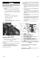
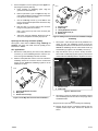
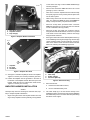
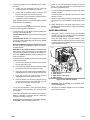
-J06051
REV. 2014-11-01
AMPLIFIER INSTALLATION KIT FOR BOOM! AUDIO STAGE II
FAIRING LOWER SPEAKERS
Electrical Overload
GENERAL
Dealer installation is recommended. Radio EQ update using
the Digital Technician® II diagnostic tool is:
•
Recommended before speaker INSTALLATION
•
Required before audio system OPERATION.
•
Only available through authorized Harley-Davidson
dealers.
Kit Number
76000586
Models
For model fitment information, see the P&A retail catalog or
the Parts and Accessories section of www.harley-davidson.com
(English only).
This kit does not fit Twin-Cooled models.
This kit is not compatible with premium bag liners. Fitted
saddlebag linings require trimming to accommodate amplifier
mount and harness cover.
Installation Requirements
It is possible to overload your vehicle's charging system
by adding too many electrical accessories. If the combined
electrical accessories operating at any one time consume
more electrical current than the vehicle's charging system
can produce, the electrical consumption can discharge
the battery and cause damage to the vehicle's electrical
system. See an authorized Harley-Davidson dealer for
advice about the amount of current consumed by additional electrical accessories or for necessary wiring
changes. (00211c)
When installing any electrical accessory, be certain not
to exceed the maximum amperage rating of the fuse or
circuit breaker protecting the affected circuit being modified. Exceeding the maximum amperage can lead to electrical failures, which could result in death or serious injury.
(00310a)
This kit must be installed:
The amplifier installed with this kit requires up to 8 amps
more current from the electrical system.
•
Before installation of the Boom! Audio Stage II Fairing
Lower Speaker Kit (Part No. 76000353).
Kit Contents
•
After installation of a PRIMARY fairing-mounted amplifier.
The amplifier (Part No. 76000277A) installed with this kit must
be purchased separately from a Harley-Davidson dealer.
If installing more than TWO amplifiers, an AUDIO IN ThreeWay Y Connector (included in THIS kit) AND a Battery+ ThreeWay Y Connector (Part No. 70270-04A, available separately)
are needed.
See Figure 11 and Table 1.
PREPARATION
To prevent accidental vehicle start-up, which could cause
death or serious injury, remove main fuse before proceeding. (00251b)
NOTE
The rider's safety depends upon the correct installation
of this kit. Use the appropriate service manual procedures.
If the procedure is not within your capabilities or you do
not have the correct tools, have a Harley-Davidson dealer
perform the installation. Improper installation of this kit
could result in death or serious injury. (00333a)
•
WITH security siren: With security fob present, turn
ignition switch ON. See the service manual. After system
is disarmed, turn ignition switch OFF. IMMEDIATELY
remove the main fuse.
•
WITHOUT security siren: See the service manual.
Remove main fuse. Turn ignition switch OFF.
NOTE
This instruction sheet references service manual information.
A service manual for this year/model motorcycle is required
for this installation. One is available from a Harley-Davidson
dealer.
-J06051
Disconnect negative (-) battery cable first. If positive (+)
cable should contact ground with negative (-) cable connected, the resulting sparks can cause a battery explosion,
which could result in death or serious injury. (00049a)
Many Harley-Davidson® Parts & Accessories are made of plastics and metals which can be recycled.
Please dispose of materials responsibly.
1 of 8
3.
When servicing the fuel system, do not smoke or allow
open flame or sparks in the vicinity. Gasoline is extremely
flammable and highly explosive, which could result in
death or serious injury. (00330a)
1.
See the service manual to perform the following generalized steps:
Use the template (1) to cut the openings in the saddlebag
for the fairing lower amplifier 18-way flanged connector
[289-1A].
a.
If saddlebag lid speakers are present from a previous
installation, right side speaker wires could be in the
connector cutout location. Remove the wire and
grommet.
b.
Carefully cut the opening (4) in the template (1) for
connector [289-1A].
c.
Place the template on the saddlebag. Align the
grommet (2) and latch fastener (3) openings. Trace
the cut outline (4) for connector [289-1A] onto the
saddlebag.
d.
Drill two pilot holes (5) for the connector flange
mounting locations.
e.
Remove template. Verify size of opening (4) with the
18-way flanged connector [289-1A] on the saddlebag
harness (see Figure 11, Item 7) from the kit.
a.
Remove seat. Retain all seat mounting hardware.
b.
Remove the ECM caddy from the top of the battery.
c.
Disconnect both battery cables, negative battery cable
first.
d.
Remove battery.
e.
Remove fuel tank console. Remove fuel tank.
f.
See Figure 1. Remove the wire trough cover.
g.
Remove right side cover.
h.
Remove left side cover.
f.
i.
Remove the two bolts attaching the electrical caddy
under the left side cover.
Cut the opening (4) for connector [289-1A] into the
saddlebag wall.
g.
Drill two 9/32 in (7.25 mm) mounting holes (5).
is08502
is07733
2
3
5
Figure 1. Wire Trough
AMPLIFIER INSTALLATION
1.
Remove all items from the right saddlebag. Remove
saddlebag. Remove bag liners (if present).
NOTE
To minimize damage to paint during cutting and drilling. use
masking tape.
2.
See Figure 2. Place the saddlebag on a protected surface
with the mounting (inboard) side facing up.
Cut openings for amplifier connector [289-1]:
See Figure 2, Items 4 and 5.
1.
2.
3.
4.
5.
6.
7.
8.
9.
4
1
6
9
7
8
Template
Saddlebag rear grommet
Saddlebag rear latch fastener (4)
Connector [289-1A] cutout
Connector [289-1A] flange mounting hole (2)
Connector [289-2A] cutout
Connector [289-2A] flange mounting hole (4)
Connector [C36A] cutout (if needed)
Connector [C36A] flange mounting hole (4) (if
needed)
Figure 2. Right Saddlebag Drilling For Stage II Amplifier
Installation
Cut openings for four-way connector [289-2]:
See Figure 2, Items 6 and 7.
NOTE
DO NOT drill four-way connector openings (Items 8 and 9)
unless using saddlebag speakers.
-J06051
2 of 8
4.
Use the template to cut the openings for the upper fourway flanged connector [289-2A].
a.
is08497
Place template on saddlebag again. Align the
grommet and latch fasteners.
b.
4
3
Drill four pilot holes (7) for the upper four-way connector [289-2A] flange mounting locations. Drill a pilot
hole (6) for the connector location.
c.
Get the saddlebag harness (7) from this kit. See
Figure 3. Verify pilot hole placement with the four-way
flanged connector.
d.
Drill four 3/16 in (4.5 mm) holes at the connector
flange mounting pilot hole locations.
1
2
1.
2.
3.
4.
5.
Drill a 7/8 in (22.5 mm) hole at the connector pilot
hole location.
e.
Test-fit the connector [289-2A]. Shape the hole as
seen on the template if necessary for proper fit.
5
Harness cover
Cable strap
18-way bulkhead connector
Socket head screw (2)
Washer (2)
Figure 4. 18-Way Connector and Cover Installation to Right
Saddlebag
Openings for four-way connector [C36A]:
See Figure 2, Items 8 and 9. ONLY if using saddlebag lid
speakers, drill holes and install connector [C36A] per the
instructions in that kit.
7.
See Figure 4. Insert the pin side 18-way bulkhead connector (3) from the saddlebag harness through the
saddlebag hole from the inside. Secure the connector from
outside the saddlebag with two socket head screws (4)
and washers (5). Tighten to 35-40 in-lbs (4.0-4.5 N-m).
8.
Snap the harness cover (1) over the 18-way connector.
Secure with a cable strap (2) (see Figure 5). The harness
routes inside the saddlebag after the amplifier is mounted.
ALL applications:
5.
Remove the metal plate (2) from the four-way bulkhead
connector (1) on the saddlebag harness. Insert the connector through the saddlebag hole from the inside.
6.
Slide the metal plate back onto the connector outside the
saddlebag. Secure the connector with four socket head
screws (3) from inside the saddlebag. Tighten to 35-40
in-lbs (4.0-4.5 N-m).
is08498
is07749a
1
2
1
2
3
1. Harness cover
2. Cable strap
1. Four-way bulkhead connector
2. Metal plate
3. Socket head screw (4)
Figure 3. Four-Way Harness Connector Installation
Figure 5. Harness Cover
9.
See Figure 6. Clean the inside rear and bottom surfaces
of the saddlebag with a 50-50 mixture of isopropyl alcohol
and distilled water.
NOTE
Verify that all four tape strips are contacting the saddlebag.
10. Remove the four pieces of protective backing from the
amplifier bracket tape strips. Position the bracket as
shown.
-J06051
3 of 8
on the vehicle. The large connector does not fit through
narrower passages.
is07750a
2
1
•
Route all wire harnesses under the frame rail to avoid
pinching by covers or the seat.
•
Take care to route ALL amplifier harness branches away
from spark plug wires. Close proximity induces spark noise
into the audio system.
•
When routing wires from one side of the vehicle to the
other, tuck harnesses under the frame tray behind the
battery to keep the battery compartment accessible.
•
Route the six-way black, pink-wired audio connectors
under the right frame rail, into the right side cover. Bundle
in front of the ABS module (if present).
•
Route the six-way, gray Data Link Connectors (DLCs)
along the left frame rail. Bundle the connectors in a pocket
of the frame in front of the battery, under the wire trough
along the frame backbone.
1.
See Figure 8. Route the vehicle-side amplifier harness (1)
in the saddlebag mounting area, beginning with the large
18-way amplifier socket connector [289-1A], moving forward on the vehicle. Route the harness around the rear
brake rotor, following the saddlebag support rail.
3
1. Area to be cleaned
2. Amplifier bracket
3. Tape strip (4)
Figure 6. Amplifier Bracket Installation
is07751
1
is07757
3
2
1
4
3
2
1. Amplifier
2. Pin stud
3. Grommets
Figure 7. Amplifier Pin Studs
1.
2.
3.
4.
11. See Figure 7. Install the amplifier pin studs in the amplifier.
Tighten to 7-9 ft-lbs (9.4-12.2 Nm). Install the grommets.
12. Position the amplifier with the grommets in the holes in
the bottom of the amplifier bracket. Slide the top into the
bracket. Install the two hex socket button head screws.
Tighten to 7-9 ft-lbs (9.4-12.2 Nm).
Figure 8. Harness Routing
2.
AMPLIFIER HARNESS INSTALLATION
NOTES
These tips help make sure all wiring fits under the seat, especially in multiple amplifier installations:
•
Begin routing the vehicle-side amplifier harness from the
large 18-way amplifier connector [289-1B], moving forward
-J06051
Secondary Amplifier Harness (69201090)
Cable strap
Fender support
Connector [289-1A]
3.
Route the harness:
a.
behind and underneath the frame,
b.
into the underseat battery area.
Use cable straps (2) to tie the harness loosely to the
saddlebag support. Use the large hole near the saddlebag
rear attachment point or one of the cable strap slots along
the bottom of the support.
4 of 8
4.
Temporarily install the right saddlebag into the support
assembly.
8.
Confirm that the vehicle-side harness connectors
comfortably reach the saddlebag connectors.
Route the long harness branch forward, into the wire
trough, to the right side. At the front of the trough, route
the wires to the fairing lowers:
•
Confirm that the amplifier harness connectors and
harness routing are clear of all moving parts.
Connectors [36RT] and [36RW] to the right lower fairing
speaker enclosure.
•
Confirm that no contact is made at full extension and
compression of the shock absorber.
Connectors [37LT] and [37LW] to the left lower fairing
speaker enclosure.
9.
When sufficient clearance is confirmed, tighten the cable
straps. Remove the saddlebag.
Get the two split rubber grommets (14) from the kit. Install
one grommet over each amplifier harness speaker wire
set.
NOTE
Continue routing the harness forward on the vehicle. Heed the
tips found at the beginning of this section.
10. Follow instructions in the Boom! Audio Fairing Lower
Speaker Kit for wiring hole location, drilling and completing
the installation.
5.
SADDLEBAG WIRING
a.
b.
c.
Locate the black, four-way Molex connector [296A] near
the back of the underseat area.
1.
FLHX/FLTRX models: On a jumper harness coming from
the fairing.
FLHTCU/FLHTK models: On an adapter harness with
two 16-way ([162C] and [162D]) and two four-way ([296A]
and (297B]) connectors.
See Figure 9. Plug in connector [149] of the saddlebag
harness to the top of the amplifier. Route the saddlebag
side harness inside the left saddlebag.
Clean the inside bottom and side surfaces of the
saddlebag along the harness path with a 50-50 mixture
of isopropyl alcohol and distilled water. Secure with cable
straps and bases as shown.
With ONLY ONE Stage II amplifier installed in the rear:
Remove the plug in the [296A] connector. Connect the
amplifier harness.
is07753b
1
With TWO or more Stage II amplifiers installed in the
rear: Plug the audio input harness (15) from this kit into
connector halves [296A] and (297B] on the adapter harness. Plug amplifier harness connector [296A] into the
audio input harness.
6.
•
Locate the gray six-way Data Link Connector (DLC) [91A]
in the electrical caddy.
a.
Cut the tether attaching the weather cap around the
harness. Remove the cap.
b.
Pull connector [91A] back through the electrical caddy
to a location under the seat, behind the caddy.
c.
Plug in gray six-way socket connector [91B] from the
amplifier harness to connector [91A] under the seat.
d.
Route gray six-way pin connector [91A] from the
amplifier harness into the electrical caddy.
e.
Insert the weather cap removed in Step 6a into the
new pin connector [91A]. Use a cable strap (17) from
the kit to attach the tether to the harness.
NOTES
If more than two amplifiers or other accessories already
use the ground post of the battery, use one of the frame
ground studs.
•
If more than two amplifiers are installed on the vehicle, a
Battery+ Three-Way Y Connector (Part No. 70270-04A,
available separately) is required.
7.
Route the battery terminal branch to the battery terminals,
but DO NOT connect the battery cables now.
-J06051
2
3
4
1.
2.
3.
4.
Amplifier harness connector
Wire harness
Wire harness cable strap
Wire harness
Figure 9. Inner Harness Routing
2.
Saddlebag liners (if present): Trim saddlebag liners.
Install saddlebag liners.
3.
See Figure 10. Install the amplifier cover on the bracket.
Secure with three clips.
5 of 8
COMPLETION
is07755
1
NOTE
To prevent possible damage to the sound system, verify that
the ignition switch is OFF before attaching the battery cables.
2
Connect positive (+) battery cable first. If positive (+) cable
should contact ground with negative (-) cable connected,
the resulting sparks can cause a battery explosion, which
could result in death or serious injury. (00068a)
1.
1. Clip, push-in (3)
2. Amplifier cover
Figure 10. Amplifier Cover
See the service manual. Connect the battery terminal
branch to the battery terminals (red positive cable first).
a.
Position the + ring terminal onto the positive battery
terminal. Install the bolt.
b.
Position the in-line fuse holder in a location that can
be easily accessed.
4.
Install the saddlebags. Plug in all saddlebag connectors.
c.
5.
Attach the new saddlebag capacity label (12) over the
existing label in the right saddlebag. Note the revised load
limit for the right saddlebag due to the amplifier installation.
Position the - ring terminal onto the negative battery
terminal. Install the bolt.
d.
Tighten both bolts to 60-70 in-lbs (6.8-7.9 N-m).
6.
See the service manual. Install the wire trough cover.
7.
Install the fuel tank per the service manual. Install the fuel
tank console.
8.
Install the electrical caddy under the left side cover with
the two bolts removed earlier. Tighten the bolts to 72-96
in-lbs (8.1-10.8 N-m).
9.
Install left side cover.
10. Install right side cover.
-J06051
2.
Apply a light coat of petroleum jelly or corrosion retardant
material to battery terminals.
3.
Install the ECM caddy per the service manual.
After installing seat, pull upward on seat to be sure it is
locked in position. While riding, a loose seat can shift
causing loss of control, which could result in death or
serious injury. (00070b)
4.
See the service manual. Install seat.
5.
Install main fuse.
6 of 8
SERVICE PARTS
is08495
9
[91A]
8
7
[91B]
6
[289-1B]
[289-1A]
[GND]
[43]
[149]
[GND]
[160A/B]
[296]
[289-2B]
[289-2A]
[36LT]
10
11
2
9
8
[37LT]
[37LW]
A
1
[36LW]
B
[160]
4
3
7
10
15
13
5
[296]
12
14
17
16
Figure 11. Service Parts, Amplifier Installation Kit For Boom! Audio Fairing Lower Speakers
-J06051
7 of 8
SERVICE PARTS
Table 1. Service Parts
Item
Description (Quantity)
Part Number
1
Amplifier bracket
76000282A
2
Screw, hex socket button head (2),
1/4-20 x 0.62 in (16 mm) long, Grade 8, with lock patch
926
3
Pin stud (2)
12600087
4
Cover, amplifier
76000502
5
Clip, push-in (3)
12600068
6
Wire harness, vehicle side, Boom! Audio Stage II fairing lower speaker
69201090
7
Wire harness, saddlebag side, Boom! Audio Stage II fairing lower speaker
69201091
8
Screw, hex socket head, M5-0.8 x 0.47 in (12 mm) long (2)
3798M
9
Flat washer, M5 (2)
6454
10
Screw, pan head, TORX, #8-32 x 0.62 in (16 mm) long, stainless, with lock patch (4)
10200065
11
Cover, saddlebag amplifier connector
69200586
12
Saddlebag capacity label
14001047
13
Drill template, saddlebag amplifier connector (right)
76000603
14
Grommet, round, 1.0 in (25.4 mm) OD, 0.38 in (9.5 mm) ID (2)
12100071
15
Wire harness, audio input
69201092
16
Base, cable strap (10)
69200342
17
Cable strap (10)
10006
Items mentioned in text, but not included in kit:
A
Amplifier (Part No. 76000277A, purchase separately)
B
Wire harness, accessory adapter (Part No. 70270-04A, purchase separately if needed)
-J06051
8 of 8