1
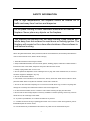
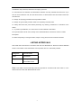
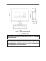
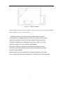
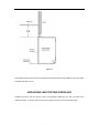
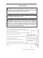
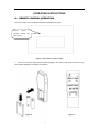
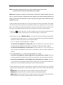
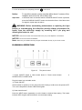
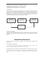
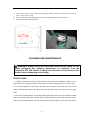
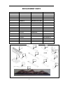
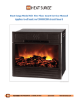
ELECTRIC FIREPLACES
SAFETY INFORMATION AND INSTALLATION MANUAL
INSERT-26-3825, INSERT-30-4026, INSERT-33-4230
Read these instructions completely before beginning installation. Failure to follow them could cause a heater
malfunction and result in serious injury and/or property damage.
WARNING: All electric heaters have hot and arcing or sparking parts inside. Do not use it in areas where
gasoline, paint or flammable liquids are stored.
WARNING: This heater is tested and listed for use only with the optional accessories listed in these
instructions. Use of optional accessories not specifically tested for this heater could void the heater warranty
and/or result in a safety hazard.
Keep this manual for future reference.
1
SAFETY INFORMATION
Due to high temperatures, the fireplace should be located out of
traffic and away from furniture and draperies.
Do not place clothing or other flammable material on or near the
fireplace. Never place any objects on the fireplace.
The fireplace can become very hot when running. Keep children and
adults away from hot surfaces to avoid burns or clothing ignition. The
fireplace will remain hot for a time after shutdown. Allow surfaces to
cool before touching.
When using electrical heaters, basic precautions, like the ones listed below, should always be followed in
order to reduce the risk of fire, electric shock and injury.
1. Read all instructions before using this heater.
2. Keep combustible materials, such as furniture, pillows, bedding, papers, clothes and curtains at least 3
feet from the front of the heater; keep them away from sides and rear as well.
3. Always unplug heater when it’s not in use.
4. Do not operate the fireplace if it has a damaged cord or plug, after it has malfunctioned, or if the unit
has been dropped or damaged in any way.
5. Do not use the heater outdoors.
6. This heater is not intended for use in bathrooms, laundry areas and similar indoor locations. Never
place the heater where it may fall into a bathtub or other water containers.
7. Do not run the cord under carpeting. Do not cover the cord with throw rugs, runners or anything else.
Arrange the cord away from traffic areas where it could not be tripped over.
8. To disconnect the heater, turn the controls to "OFF" before removing the plug from the outlet.
9. Do not insert or allow foreign objects to enter any ventilation or exhaust opening, as this may cause an
electric shock, fire or damage to the heater.
10. To prevent a possible fire, do not block air intakes in any manner.
11. A heater has hot and arcing or sparking parts inside. Do not use it in areas where gasoline, paint or
flammable liquids are used or stored.
12. Use this heater only as described in this manual. Any other use not recommended by the
2
manufacturer may cause fire, electric shock or injury to persons.
13. Avoid the use of an extension cord because the extension cord may overheat and cause a fire. If you
have to use an extension cord, the cord should be No. 14 AWG minimum size and rated not less than
1875 WATTS.
14. Always use properly grounded fused and polarized outlets.
15. Always use ground fault protection where it is required by electrical codes.
16. Always disconnect the power before performing any cleaning, maintenance or relocation of the
heater.
17. To prevent a possible fire, do not burn wood or other materials in this heater.
18 To prevent electric shock or fire, always use a certified electrician, should new circuits or outlets
be required.
19. When transporting or storing the heater, keep it in a dry place, free from excessive vibration.
LISTING APPROVALS
This heater has been tested in accordance with the CSA Standards for fixed and location-dedicated
electric room heaters in the United States. All components are UL or CSA safety certified.
Voltage/Hz
120VAC,60Hz
Watts:
1500Watts
Amps:
15Amps
Grounded Circuit
Note: This heater must be electrically wired and grounded in accordance with local codes or, in the
absence of local codes, with National Electric Code.
3
PRODUCT DIMENSION
Figure 1
INSERT-26-3825 dimensions
Figure 2
INSERT-30-4026 dimensions
4
Figure 3
INSERT-33-4230 dimensions
Locating FIREPLACE
WARNING: Never locate this heater where it may fall into a bathtub or
any water container.
NOTICE: Minimum and maximum clearances must be maintained at all
times. Illustrations throughout these instructions reflect typical
installations and are for design purposes only. Actual installations may
vary slightly due to individual preferences.
5
Figure 4
Heater Locations
Figure 8 illustrates a variety of ways the heater may be located in a room. The heater may be installed
directly on the floor, carpet or raised on a hearth.
WARNING: RISK OF FIRE. MAINTAIN ALL SPECIFIED AIR SPACE
CLEARANCES TO COMBUSTIBLES. FAILURE TO COMPLY WITH THESE
INSTRUCTIONS MAY CAUSE A FIRE OR CAUSE THE APPLIANCE TO
OVERHEAT. ENSURE ALL CLEARANCES (I.E. BACK, SIDE, TOP, VENT
MANTEL, FRONT, ETC.) ARE CLEARLY MAINTAINED.
APPLIANCE VENTS LOCATED ON THE FRONT AND BACK OF THIS
ELECTRIC APPLIANCE CANNOT IN ANY WAY BE COVERED AS IT MAY
CREATE A FIRE HAZARD.
WHEN USING PAINT OR LACQUER TO FINISH THE MANTEL,THE PAINT
OR LACQUER MUST BE HEAT RESISTANT TO PREVENT DISCOLOURATION.
6
Figure 5
The minimum distance from the top of the appliance that the mantel can be installed is 5cm,at any depth.
The sides and back are 1cm.
UNPACKING AND TESTING FIREPLACE
Carefully remove the unit from the box. Prior to permanently installing the unit, test it to make sure it
operates properly. To do this, plug the unit's power supply cord into a 120-volt grounded outlet.
7
INSTALLATION
CAUTION: The unit's power supply cord must be connected to a
properly grounded and protected 120-volt outlet. Always use ground
fault protection where required by the electrical code.
WARNING - RISK OF FIRE! To prevent a possible fire, do not block
the air intake or exhaust in any manner.
WARNING - RISK OF FIRE! The power cord must not be pinched or
placed against a sharp edge. Secure the cord to avoid tripping or
snagging thus reducing the risk of fire, electric shock or personal
injury. Do not run the cord under carpeting. Do not cover the cord
with throw rugs, runners or similar items. Arrange the cord away from
traffic areas where it could be tripped over.
Once the mantel has been prepared, the fireplace can be installed.
Select a suitable location that is not susceptible to moisture and is away from
drapes, furniture and high traffic areas.
Note: Follow all national and local electrical codes. This insert can be installed
into an existing mantle or as a new construction.
Unscrew
and
remove
1. Unplug the unit and turn the power switch to the “ON” position.
the screws on both
2. Push the fireplace into the mantel.
sides of the unit before
3. Plug the fireplace into a 15amp/120V, grounded outlet.
you place the fireplace
into the mantel.
Note: Unscrew and remove the screws on both
sides of the unit before you place the fireplace into the
mantel.
Figure 6
8
The location of screw
OPERATING INSTRUCTIONS
A: REMOTE CONTROL OPERATION
The power switch and control panel are located behind the front glass .
Power
switch
located behind
glass panel
is
the
Figure 7 The location of power switch
1.
For remote to function make sure the heater is plugged-in and mains power switch located on the up
left hand side behind the front glass is at position I.
Figure 8
Figure 9
9
Note. The heating and flame function can only be operated by the remote control.
The remote control needs 2 pcs AA batteries (not included).
Note: When the heater is turned on for the first time, it may release a slight, harmless odor. This
odor is a normal occurrence caused by the initial heating of the internal heating elements and
should not occur after the initial burn off. (This odor may occur again if dust or debris has been
trapped in the unit.)
2. When operating the remote make sure you point the remote to the centre of the heater unit and make
sure each time you press the button the LED indicator located on top right hand corner of the remote
blinks. If the LED fails to blink check the batteries. It takes some time for the receiver to respond to the
transmitter. Do not PRESS the buttons more than once within two seconds for correct operation.
3. Power on
button: The power – on button at top left corner of the remote is the mains ON/ OFF
power button. This will turn off all the functions and the heater will be in standby mode.
4. Flame Power On button ” DISPLAY ON OFF”: This button controls both the ember and flame effect.
Once the flame effect is ON use the + and – buttons as explained below to adjust the flame brightness
as desired. Press this button again to turn OFF the flame effect.
a. The – or + buttons control the brightness of
EMBER.
To increase the brightness of ember bed, press and release the + button. Each time you
press this button the brightness will increase by a small amount, until the maximum is reached.
To decrease the brightness of ember bed, press and release the – button. Each time you
press this button the brightness will decrease by small amount, until the minimum brightness is
reached.
b. The FLAME INTENSITY– or + buttons control the brightness of
FLAME.
To increase the brightness / flame height, press and release the + button. Each time
you press this button the brightness will increase by a small amount, until the maximum is reached.
To decrease the brightness / flame height, press and release the – button . Each time
you press this button the brightness will decrease by small amount, unitl the minimum brightness is
reached. You can mix the ember and the flame to create a realistic flame effect.
5. Heater On/off button: This button is the heater ON / OFF button. Press this button to turn the heater
ON. The heater will always start at high heat setting 1500W. To turn OFF the heater press this button
again.
HIGH button: Press the high button to switch the heater to high heat setting 1500W.
LOW button: Press the low button to switch the heater to LOW heat setting 750W.
TEMP button: Press the TEMP. button to switch the heater to AUTO mode. Under this mode the
heater will operate in similar way as explained below for the manual o0peration.
10
6. To turn off the heater unit completely press the
button once.
Notice:
To work the remote control must be within about 6 metres of the
fireplace and not too far off to either side.
Important!
If the flame does not activate after the POWER ON/OFF button is pressed,
press the DISPLAY ON/OFF button to activate the flame. If the flame does
not appear, repeat steps as above
WARNING: Before undertaking maintenance or replacing the light
bulb(s) or interchanging the reflection panel(s) always disconnect the
heater from the electricity supply by removing the 3 pin plug and
allowing the heater to cool.
NOTICE: This remote control must remain within 26 ft. (8 m) of the fireplace to be effective.
NOTICE: Do not mix old and new batteries.
Note: Make sure your batteries are fully charged and installed correctly in your remote control.
B: MANUAL OPERATION
Figure 10
The panel control
1. Power ON/OFF switch 2. Heat control button 3. Flame control button
HEATER LED 5. POWER LED
4.
Plug the heater into a suitable outlet.
1) “Power ON/OFF”
Set this switch to position I to turn the product ON. Setting it to O to turn the product OFF.
Turn on the fireplace the Power LED will be lighten.
2) “Heat control button”
Press the HEAT button repeatedly to set the heater to desired heat setting. The heater
indicator LED will glow which shows the current heater setting.
11
HEATER INDICATOR LED RED –1500W HEAT OUTPUT
HEATER INDICATOR LED BLUE—750W HEAT OUTPUT
HEATER INDICATIOR LED PURPLE—AUTO MODE
AUTO MODE
Under this mode the heater will automatically turn ON at high heat setting 1500W heat
output when the room temperature drops below 22 ℃. When the room temperature is
between 22-25℃ the heater output will switch to low heat setting 750W. When the room
temperature goes above 25℃ the heater will be turned off and the cycle will continue.
The LED indicator will be PURPLE in colour under this mode.
HIGH / 1500W
LOW / 750W
AUTO MODE
HEATER INDICATOR
HEATER INDICATOR
HEATER INDICATOR
LED COLOUR - RED
LED COLOUR - BLUE
COLOUR - PURPLE
OFF
3) “Flame control button”
Press the Flame brightness adjustment button to adjust the flame height and ember bed
brightness. Press and release the FLAME control button to cycle through LO, MED, HI
and OFF.
HARD-WIRE INSTALLATION
Warning: ENSURE ALL POWER IS TURNED OFF BEFORE HARD WIRING THIS
APPLIANCE.
HARD WIRING CONNECTION
If it is necessary to hard wire this appliance, a qualified electrician may remove the cord
connection, and wire the appliance directly to the house hold wiring.
This appliance must be electrically connected and grounded in accordance with local codes, if
hard wired. In the absence of local codes, use the current CSA C22.1 CANADIAN ELECTRICAL
CODE in Canada or the current ANSI/NFPA 70 NATIONAL ELECTRICAL CODE in the United
States.
12
A. Unscrew two screw show in the below left figure. Remove the cover and the power cord fix
piece, remove power cord.
B. Insert external hard wire through the power cord hole and link to the junction box.
C. Put the plate back and screw back.
CLEANING AND MAINTENANCE
WARNING: Always disconnect the power and allow the heater to cool
before performing any cleaning, maintenance or relocation. Turn the
controls to OFF and remove the plug from the outlet or turn off the circuit
breaker before attempting any cleaning.
FRONT GLASS
1. The glass is cleaned in the factory during assembly. During shipment, installation, handling, etc. the
glass surface may collect dust particles. These can be removed by buffing lightly with a clean dry cloth.
2. To remove fingerprints or other marks, the glass can be cleaned with a damp cloth using a good
quality household glass cleaner. The glass should be completely dried with a lint free cloth or paper
towel.
3. In the event of glass breakage, vacuum all remaining glass pieces with a shop vac. DO NOT VACUUM
WHILE THE PIECES ARE HOT. Replace glass only with replacement parts made specifically for this
heater. Never substitute material. Only fully tempered soda lime safety glass may be used on this heater.
13
REPLACEMENT PARTS
REF NO
PART NO.
DESCRIPTION
REMARK
1
FRT60420
HEATER ASSEMBLY
REMARK
2
LRC8
CIRCULT BOARD
3
301506
REMOTE RECEIVER
4
385506
3W LED ASSEMBLY
5
LED-M1-10
LED STRIP FOR FLAME
6
LED-M-2
LED STRIP FOR FLME
7
LED-M2-10
LED STRIP FOR LOG
8
LED-M3-2
LED STRIP FOR LOG
9
LED-M1-12
LED STRIP FOR EMBER
10
LED-M-12
LED STRIP FOR EMBER
11
10105031B
REMOTE
12
10101201
FLAME MOTE
13
10104010
SWITCH
14
10305506
LOG
ZECL/INSERT 26
10305507
ZECL/INSERT 30
10305508
ZECL/INSERT 33
10305509
ZECL39
10305510
ZECL2939
5
6
1
11
7
3
8
2
12
9
4
10
13
14
14
TROUBLE SHOOTING
WARNING: Turn off the appliance and let it cool before servicing it.
Only a qualified service person should service and repair the heater.
OBSERVED PROBLEM
POSSIBLE CAUSE
REMEDY
Fireplace turns off and will not
Fireplace has overheated and
Reset switch by turning main
turn on
safety device has caused
power switch off and waiting five
thermal switch to disconnect or
minutes, then turning it back on
home circuit breaker has opened
Log set and/or ember is dark
Wiring is loose
Inspect wiring for loose
connections and repair or
replace if necessary
Flame is not moving
Flame motor is defective
Call a qualified service
technician
Remote control does not work
Low Batteries
Replace AA batteries in remote
Power switch is in OFF position
control
Turn on the main power switch
Heater does not provide heat
Thermal switch has been
Turn the unit off and unplug the
when turned on
tripped.
unit for five minutes. Plug back in
Circuit breaker has been tripped
and turn the unit on. If plug can
not be reached, follow directions
for tripped circuit breaker
Turn off circuit breaker that
supplies electricity to the
unit .Wait five minutes then flip
circuit breaker back on.
15