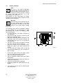
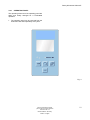
1
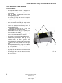
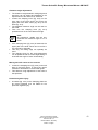
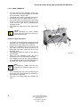
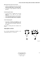
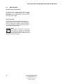
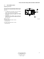
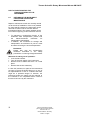
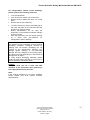
Thermo Scientific Rotary Microtome Microm HM 340 E
Thermo Scientific
ROTARY MICROTOME
Microm HM 340 E
INSTRUCTION MANUAL
Microm International GmbH
part of Thermo Fisher Scientific
Otto-Hahn-Str. 1A
69190 Walldorf / Germany
387831 - English
1
Thermo Scientific Rotary Microtome Microm HM 340 E
2
Microm International GmbH
part of Thermo Fisher Scientific
Otto-Hahn-Str. 1A
69190 Walldorf / Germany
387831 - English
Thermo Scientific Rotary Microtome Microm HM 340 E
CERTIFICATION
Thermo Fisher Scientific Microm International GmbH certifies that this
instrument has been tested and checked carefully. Its technical data was
verified before shipment to be in accordance with the published specifications.
The instrument complies with applicable international safety regulations.
WARRANTY
This product is warranted against defects in material and workmanship for a
period of 1 year. Parts which prove to be defective during the warranty period
will be repaired or replaced free of charge by Thermo Fisher Scientific Microm
International GmbH. No other warranty is expressed or implied. Unauthorized
modification or repair by third party persons will void the warranty. The warranty
will expire in case of improper or wrong use of the instrument and in case the
warning and precautionary messages are not observed. Thermo Fisher
Scientific Microm International GmbH is not liable for any occurring damage.
Errors and omissions excepted. Subject to amendment and improvement
without further notice.
This instruction manual will be supplied together with each instrument.
Further copies can be ordered at the nearest sales office by giving the serial
number of the instrument, the number of the instruction manual and the date
of issue.
This instruction manual is available in the following languages:
German:
English:
French:
Spanish:
Italian:
Cat. no.
387830
387831
387832
387833
387834
Microm International GmbH
part of Thermo Fisher Scientific
Otto-Hahn-Str. 1A
69190 Walldorf / Germany
387831 - English
3
Thermo Scientific Rotary Microtome Microm HM 340 E
Dear Customer,
Thank you for buying this instrument.
Before putting the instrument into operation, please read these operating
instructions carefully to familiarize yourself with its proper operation and
functions. To avoid risks for the operator and technical damage to the
instrument, it must only be used in accordance with its intended use (see
part 1-2).
Any other use of the instrument is considered improper! All warranties and
guarantees would then be null and void.
Only skilled or specially trained personnel must operate the microtome, i.e.
clamping the specimen, trimming and first-cuts, sectioning and transferring
sections onto a slide. The listed and marked safety measures as well as the
regulations and hygiene measures of your respective lab must strictly be
observed.
Serial number: ....................................................................................
Please check the Ser. No. on the type plate, which is placed on the rear side
of your instrument and enter this number here. This way, questions and
service can be handled faster.
Instruction manual no. 387831
Issued on March 15th, 2011
Microm International GmbH
part of Thermo Fisher Scientific
Otto-Hahn-Str. 1A
69190 Walldorf
Germany
Phone:
Fax:
Email:
Internet:
4
+49.(0)6227.836-0
+49.(0)6227.836-111
[email protected]
www.thermoscientific.com
Microm International GmbH
part of Thermo Fisher Scientific
Otto-Hahn-Str. 1A
69190 Walldorf / Germany
387831 - English
Thermo Scientific Rotary Microtome Microm HM 340 E
Table of contents
PART 1 IMPORTANT INFORMATION
1-1
Safety precautions and symbols
1-2
Intended use
PART 2 INTRODUCTION
2-1
2-2
2-2-1
2-2-2
2-3
Description Rotary Microtome HM 340 E
Accessories
Standard equipment
Additional equipment (optional)
Technical data Rotary Microtome HM 340 E
PART 3 OPERATING INSTRUCTIONS
3-1
3-2
3-2-1
3-3
3-3-1
3-3-1-1
3-3-1-2
3-3-1-3
3-4
3-4-1
3-4-2
Setting up the microtome
Initial turn-on
Operating panel
Display and key functions
Indication of cutting processes
Section counter
Section thickness sum
Remaining travel to front end position
Setting section thickness and trimming thickness
Trimming and first cuts
Fine feed
3-5
Cutting movement and retraction
3-6
Locking and unlocking the handwheel
3-7
3-7-1
Feed
Specimen coarse feed and speed for coarse feed
3-8
3-8-1
3-8-2
3-8-3
3-8-4
Menu
Date and time
Display mode
Turning off the function "Retraction"
Language selection for the display
3-9
3-9-1
3-9-2
3-9-3
3-9-4
Adapters for specimen clamping
Adapter, non-orienting
Adapter, orienting, specimen orientation
Clamping and/or changing specimen clamps
Readjusting specimen clamps
Microm International GmbH
part of Thermo Fisher Scientific
Otto-Hahn-Str. 1A
69190 Walldorf / Germany
387831 - English
5
Thermo Scientific Rotary Microtome Microm HM 340 E
3-10
3-10-1
3-10-2
3-10-3
3-10-4
3-10-5
3-10-6
Specimen clamping
Universal cassette clamp
Universal cassette clamp, adjustable
Standard specimen clamp
Insert for round specimen clamps, V insert and V distance piece
Foil clamp
Segment arc and universal specimen holder
3-11
3-11-1
3-11-2
3-11-3
3-11-4
Knife carrier
Disposable blade carrier ER
Disposable blade carrier E
Knife carrier C
Readjusting the knife carrier
3-12
Section waste tray
3-13
Memory function
3-14
Large field magnifier
PART 4 WORKING WITH THE MICROTOME
4-1
Sectioning instructions
4-2
How to avoid malfunctions
4-3
Possible sources of errors – cause and removal
PART 5 MAINTENANCE AND CARE
5-1
Cleaning and care
5-2
Maintenance
5-3
Replacement work
PART 6 CONDITIONS FOR THE TRANSPORTATION OF THE INSTRUMENT
6
6-1
Returning the instrument for repair and routine maintenance
6-2
Disposal of the instrument after final shutdown
Microm International GmbH
part of Thermo Fisher Scientific
Otto-Hahn-Str. 1A
69190 Walldorf / Germany
387831 - English
Thermo Scientific Rotary Microtome Microm HM 340 E
PART 1
IMPORTANT INFORMATION
1-1
WARNING SIGNALS AND SYMBOLS
The installation and routine use of the HM 340 E is easy and safe if the instructions in this manual are being
observed.
Note:
Special instructions regarding operation of the instrument.
Warning:
Special precautionary measures to prevent damage to equipment. For a long lifetime of the
equipment, please observe these instructions carefully.
Caution – general danger spot:
The instruction manual must strictly be observed whenever this symbol is visible on the
instrument.
Hazard of hand injuries:
Due to moving parts in connection also with the microtome knife, a danger area arises, which
might lead to hand injuries in case of non-compliance with the safety features of the microtome
and when disregarding the instruction manual.
Biohazard:
Warning of biological danger.
Radioactivity:
Warning of radioactive danger.
Chemicals :
Warning of unhealthy or irritating substances.
Separate taking back of electrical and electronic instruments in the countries of the
European Union:
This is to be applied in the countries of the European Union and other European countries with a
separate collecting system within the waste management.
This product, being an electro and/or electronic instrument, must be treated separately within
the waste management process (WEEE).
Microm International GmbH
part of Thermo Fisher Scientific
Otto-Hahn-Str. 1A
69190 Walldorf / Germany
387831 - English
7
Thermo Scientific Rotary Microtome Microm HM 340 E
SAFETY PRECAUTIONS AND IMPORTANT INFORMATION
CAUTION!
The operator's safety is affected, when the instrument is not operated in accordance with this
instruction manual.
Please observe the following general precautions during operation of this instrument. Failure to
comply with these precautions violates safety standards and the intended use of the instrument.
Thermo Fisher Scientific Microm International GmbH is not liable for misuse of the instruments and
failure to comply with basic safety requirements.
INSTRUMENT GROUNDING
To avoid injury from electrical current, the instrument must be connected with the protective earth. The
instrument is equipped with a three wire ground plug. The power outlet must be connected to the protective
earth and must meet the International Electrotechnical Commission (IEC) regulations.
CAUTION: MAINS VOLTAGE
Never remove instrument covers during operation. Component replacements as well as adjustments must
only be made by trained service personnel. Only use original spare parts for replacement work. Unplug the
unit before removing or opening the covers.
CARE IN USING MICROTOME KNIFE
To diminish the danger of being injured by the knife or blade, use the knife guard when adjusting specimen
and knife. If possible, the specimen should be clamped in before the knife is inserted into the knife holder.
Before changing the knife holder, always remove blade or knife! Unused knives should always be kept in a
knife case. Never place the knife with the cutting edge upwards. Never try to catch a dropping knife!! Never
check the sharpness of the cutting edge with your fingers. The cutting edge is extremely sharp!
HAZARD OF RADIOACTIVE RADIATION
When working with radioactive specimens observe all applicable radiation safety procedures. When working
with radioactive contaminated material, appropriate safety and disinfection measures must be carried out.
According to the rules and regulations concerning the handling of radioactive contaminated material of the
respective laboratory, safety clothing (e.g. particle mask, gloves, protective shoe covers) must be worn.
Radioactive contaminated waste must be disposed of according to the respective regulations.
8
Microm International GmbH
part of Thermo Fisher Scientific
Otto-Hahn-Str. 1A
69190 Walldorf / Germany
387831 - English
Thermo Scientific Rotary Microtome Microm HM 340 E
HAZARD OF INFECTION
Specimens used during the intended operation of the instrument might potentially be infectious. For this
reason, it is recommended to observe the general laboratory regulations concerning protection against
danger of infection.
Information on decontamination media, their use, dilution and effective range of application can be read in
the Laboratory Biosafety Manual : 1984 of the World Health Organization.
When working with infectious specimens observe all applicable safety procedures. When working with
infectious material, appropriate safety and disinfection measures must be carried out. According to the rules
and regulations concerning the handling of infectious material of the respective laboratory, safety clothing
(e.g. particle mask, gloves, protective shoe covers) must be worn. Infectious waste must be disposed of
according to the respective regulations.
WASTE DISPOSAL
All debris, waste as well as infectious and radioactive contaminated material from operation must be
disposed of in accordance with the respective regulations of the lab. Section waste must be disposed of
according to the respective regulations for special waste.
HAZARD OF MALFUNCTION
To avoid the hazard of malfunction of an instrument, it must only be operated in a controlled electromagnetic
environment. This means, that transmitters such as mobile phones must not be operated in their close
vicinity.
In case of malfunctions and/or service work, please turn off the instrument and contact your local dealer.
DANGER IN EXPLOSIVE ENVIRONMENT
The instrument must not be operated in the presence of flammable gases.
Microm International GmbH
part of Thermo Fisher Scientific
Otto-Hahn-Str. 1A
69190 Walldorf / Germany
387831 - English
9
Thermo Scientific Rotary Microtome Microm HM 340 E
1-2
INTENDED USE
The Rotary Microtome HM 340 E from Thermo Fisher Scientific Microm International GmbH is a highly
efficient multi-purpose microtome which can be used for paraffin, hard- and semithin-sectioning techniques in
biology, medicine, industry and research.
Only skilled or specially trained personnel must operate the microtome, i.e. clamping the specimen, trimming
and first-cuts, sectioning and transferring sections onto a slide. The listed and marked safety measures as
well as the regulations and hygiene measures of your respective lab must strictly be observed.
Note:
This instruction manual is part of the product. Keep it always close to the instrument!
10
Microm International GmbH
part of Thermo Fisher Scientific
Otto-Hahn-Str. 1A
69190 Walldorf / Germany
387831 - English
Thermo Scientific Rotary Microtome Microm HM 340 E
2
INTRODUCTION
2-1
DESCRIPTION ROTARY MICROTOME HM 340 E
The Rotary Microtome HM 340 E from Thermo Fisher Scientific Microm International GmbH is a highly
efficient multi-purpose microtome which can be used for paraffin, hard- and semithin-sectioning techniques in
biology, medicine, industry and research.
The HM 340 E sets new ergonomical standards concerning operation and comfort. The instrument is
equipped with a section waste tray with integrated arm rest, which is built around and under the knife carrier
for direct collection of section waste.
This model can be equipped with all specimen clamps and knife carriers of the Rotary Microtome series. In
addition, the stereomicroscope or the large field magnifier can be adapted.
The HM 340 E will cut sections in a range from 0,5 µm up to 100 µm. For the protection of knife and
specimen, the instrument retracts the specimen at the end of the cut. If desired, the function <retraction> can
be turned off.
The motorized coarse feed system allows the continuous specimen forward and backward travel with three
different speed settings. This way, specimen and knife edge distance can be adjusted quickly.
A trimming function with defined steps from 5 µm to 500 µm permits the fine adjustment up to the first cuts
and results in larger section thicknesses when trimming.
The operating panel is installed on the left side of the microtome. It can be removed and used separately.
The selected section thickness, trimming thickness, section counter, sum of section thicknesses, remaining
travel to the front end position as well as the current date and time are indicated on the display of the
operating panel.
The knife carriers are designed so the knives can be easily clamped in place and adjusted.
In addition, the instrument is equipped with a hand wheel brake that locks in any position.
The manual rotary movement of the hand wheel of the Rotary Microtome HM 340 E is converted into a
vertical movement of the cylinder head which carries the specimen holder.
Sectioning is carried out by knives or blades, which must be adjusted and fixed on the knife carrier.
With the downward movement of the specimen, sectioning is carried out (cutting movement).
The upward return travel of the specimen is carried out by turning the hand wheel further in clockwise
direction. During this return travel, the specimen is drawn back to protect knife and specimen. If desired, the
function <retraction> can be turned off. The selected section thickness is delivered at the upper reversal
point of the return travel.
The number of the sections made can be shown on the section counter on the display. After each downward
movement of the specimen holder, the number on the section counter increases by 1. The sum of the
sections carried out can also be seen on the display. For this, trimming values and sectioning values are
added up. Section counter and sum of section thicknesses can be reset to zero at any time by means of the
RESET-button.
Moreover, the remaining travel to the front end position can also be shown on the display. The remaining
travel, which is still available for sectioning, is shown in microns. If the specimen holder is in the back end
position, the display shows 28 000 µm. This number decreases, the further the specimen holder is moved
towards the front.
The fast freezing unit K-34 allows frozen sectioning with the specimen temperature as low as -45°C.
Microm International GmbH
part of Thermo Fisher Scientific
Otto-Hahn-Str. 1A
69190 Walldorf / Germany
387831 - English
11
Thermo Scientific Rotary Microtome Microm HM 340 E
Total overview
Retraction
MENU
MEMO
Fig. 1
12
Microm International GmbH
part of Thermo Fisher Scientific
Otto-Hahn-Str. 1A
69190 Walldorf / Germany
387831 - English
Thermo Scientific Rotary Microtome Microm HM 340 E
2-2
ACCESSORIES
2-2-1
STANDARD EQUIPMENT
The Rotary Microtome HM 340 E is supplied with the following accessories:
1 Hex head wrench 6 mm
1 Cover
1 Para Gard, 100 ml
1 Instruction manual
2 Cover plates
2-2-2
ADDITIONAL EQUIPMENT (OPTIONAL)
2-2-2-1 KNIFE CARRIER
Art. Nr.
Standard knife carrier N
705670
Disposable blade carrier E
705640
Disposable blade carrier ER
705650
2-2-2-2 SPECIMEN CLAMPS
Standard specimen clamp
715010
Universal cassette clamp
Universal cassette clamp, adjustable
715020
716130
Foil clamp
715030
Sandwich supporting material
176010
Insert for round specimens, Ø 6 mm
Insert for round specimens, Ø 15 mm
Insert for round specimens, Ø 19 mm
Insert for round specimens, Ø 25 mm
715070
715080
715280
715090
V-insert
715100
V-distance piece
715320
Microm International GmbH
part of Thermo Fisher Scientific
Otto-Hahn-Str. 1A
69190 Walldorf / Germany
387831 - English
13
Thermo Scientific Rotary Microtome Microm HM 340 E
Cat. no.
Segment arc
715050
Universal specimen holder
715060
2-2-2-3 OPTICAL ACCESSORIES
Large field magnifier, 220 V
Large field magnifier, 120 V
760160
760170
Stereomicroscope Stemi 2000
755210
Adapter for Stemi 2000
532090
KL 1500 with ring illumination
230 V, 50 - 60 Hz
120 V, 50 - 60 Hz
760280
760290
2-2-2-4 MIKROTOMMESSER
Steel knives, type c
12 cm
16 cm
18,5 cm
22 cm
152010
152020
152270
152030
Steel knives, type d
12 cm
16 cm
22 cm
152060
152070
152080
Tungsten carbide knife, 16 cm, d
152120
Knife cases
12 cm
16 cm
18,5 cm
22 cm
152220
152230
152280
152240
Disposable blades for paraffin
SEC 35
SEC 35e
152200
152210
14
Microm International GmbH
part of Thermo Fisher Scientific
Otto-Hahn-Str. 1A
69190 Walldorf / Germany
387831 - English
Thermo Scientific Rotary Microtome Microm HM 340 E
2-14-5 ADDITIONAL ACCESSORIES
Fast freezing unit K 34
100 V/50 - 60 Hz
115 V/60 Hz
230 V/50 Hz
240 V/50 Hz
Section transfer system STS
100 V/50 - 60 Hz
115 V/60 Hz
230 V/50 Hz
240 V/50 Hz
Lubricating oil, 100 ml
Lubricating oil, 250 ml
350110
350120
Paraffin repellent, PARA GARD, 100 ml
350170
Microm International GmbH
part of Thermo Fisher Scientific
Otto-Hahn-Str. 1A
69190 Walldorf / Germany
387831 - English
15
Thermo Scientific Rotary Microtome Microm HM 340 E
2-3
TECHNICAL DATA HM 340 E
Microtome:
Section thickness range ......................................... 0,5 - 100 µm
Resolution .............................................. 0,5 µm from 0,5 - 2 µm
................................................................... 1 µm from 2 - 10 µm
................................................................. 2 µm from 10 - 20 µm
................................................................. 5 µm from 20 - 30 µm
............................................................... 10 µm from 30 - 40 µm
.............................................................. 20 µm from 40 - 100 µm
Trimming thickness range ...........................................5 - 500 µm
Resolution ................................................... 5 µm from 5 - 10 µm
.............................................................. 10 µm from 10 - 100 µm
............................................................ 20 µm from 100 - 200 µm
............................................................ 50 µm from 200 - 500 µm
Specimen retraction during return travel ........................... 40 µm
Horizontal feed range ...................................................... 28 mm
Vertical specimen stroke ................................................. 64 mm
Section counter:
Section thickness sum:
Remaining travel
to front end position:
......................................................................... 5-digit, with reset
......................................................................... 5-digit, with reset
Specimen size:
Specimen orientation:
when using a standard specimen clamp: .................. 55 x 50 mm
x - and y - axes........................................................ universal 8°
rotation: ...................................................................... up to 360°
Cutting drive:
Coarse feed:
................................................. manual by means of handwheel
......................................... motorized, graduated and continuous
Speed for
coarse feed:
................................................................ 400, 800 or 1200 µm/s
Storage
temperature range:
...................................................................... -20°C up to +50°C
..........................................................................................5-digit
Operating conditions:
....................... +5°C up to +40°C (at a max. rel. humidity of 60%)
............................................................altitude up to 2000 M.S.L.
.......................................................................for indoor use only
Floor loading requirements: ......................................................................................... 103 kg
16
Power requirements:
........................................ 220...230 V 200 mA +/-10% 50...60 Hz
................................................ 240 V 200 mA +/-10% 50...60 Hz
................................................ 100 V 400 mA +/-10% 50...60 Hz
................................................ 115 V 400 mA +/-10% 50...60 Hz
Pollution degree:
Overvoltage category:
Sound pressure:
................................................................................................. 2
................................................................................................. II
......................................................................................39 dB(A)
Dimensions:
........................... 410 mm x 520 mm x 280 mm (wide/deep/high)
Weight:
...........................................................................................28 kg
Microm International GmbH
part of Thermo Fisher Scientific
Otto-Hahn-Str. 1A
69190 Walldorf / Germany
387831 - English
Rotary Microtome HM 340 E
3
OPERATING INSTRUCTIONS
3-1
SETTING UP THE MICROTOME
•
•
•
•
•
Cut through the bands around the carton.
Open the carton.
Remove the accessories.
On the lower rear side of the instrument, there
is a recessed grip to lift or carry the
microtome.
Lift the microtome out of the carton.
Note:
Do not use the handwheel handles to
lift or carry the instrument.
•
•
•
•
•
•
Choose the site of installation in a way that the
switch for separating the instrument from the
voltage can be reached at any time.
Place the microtome on a stable and vibration
free table, as sectioning can be influenced by
nearby instruments which generate vibrations.
Handwheel and coarse feed wheel must be
free and accessible in a comfortable way.
Remove the separately packed section waste
tray and install it at the base plate from the
front side.
In the rear part of the base plate, there are
sliding feed for an easy moving of the
microtome.
Slightly lift the base at the front end only and
slide the microtome.
Note:
Remove the section waste tray to
move or carry the instrument. The
section waste tray can be pulled out of
its proper position.
•
Before starting section, instrument, knife
carrier and section waste tray should be
treated with a commercially available paraffin
repellent.
Note:
This medium considerable reduces the
adhesive force of paraffin sections on
the individual parts (see part 2-2-2-5,
optional accessories).
Microm International GmbH
part of Thermo Fisher Scientific
Otto-Hahn-Str. 1A
69190 Walldorf / Germany
387831 - English
17
Rotary Microtome HM 340 E
3-2
INITIAL TURN-ON
Note:
The kind of the used examination
materials and all special conditions for
their processing, pre-treatment and, if
necessary, storage as well as instrument controls
for correct and safe operation is in the
responsibility of the operator.
The operator is also responsible for special
equipment and materials and/or reagents for the
operation of the instrument.
Warning:
Before turning on the instrument for the
first time, please check if the power
requirements indicated on the type
plate correspond to the power supply voltage
being used.
The operating panel, which is separately packed,
can be attached to the instrument or used
freestanding. First connect the operating panel
with the instrument:
• A control cable (fig. 3.1) is fixed on the back of
the instrument.
• Connect this cable with the connector at the
back of the operating panel.
• Should the operating panel be attached to the
instrument, push the connector through the
corresponding hole (fig. 3.2) on the back of
the microtome.
• Turn the connector 90° and push it through
the hole on the front of the instrument.
• Plug the connector into the operating panel.
Fasten the cable on the panel with the two
screws.
• To clear away the cable, insert it into the
corresponding holders (fig. 3.3) on the back of
the microtome.
•
•
•
•
•
•
•
18
Connect the power cord to the power socket
(fig. 3.4) on the back of the instrument.
Turn on the power switch (fig. 3.5).
Then, the specimen holder moves to the back
end position.
This movement is always carried out when the
instrument is turned on.
This way, the instrument is calibrated.
Afterwards, FEED and TRIM are shown on the
display.
The insert for the two fuses is placed beside
the power switch.
Microm International GmbH
part of Thermo Fisher Scientific
Otto-Hahn-Str. 1A
69190 Walldorf / Germany
387831 - English
Fig. 3
Rotary Microtome HM 340 E
3-2-1
OPERATING PANEL
The operating elements of the operating panel are
easily and clearly arranged for a comfortable
operation.
•
The operating panel can be removed from the
instrument and used separately at any time.
Fig. 4
Microm International GmbH
part of Thermo Fisher Scientific
Otto-Hahn-Str. 1A
69190 Walldorf / Germany
387831 - English
19
Thermo Scientific Rotary Microtome Microm HM 340 E
3-3
DISPLAY AND KEY FUNCTIONS
3-3-1
INDICATION OF CUTTING PROCESSES
In the lower line of the display information about
the sectioning status can be seen.
•
Press the "scroll button" (fig. 5.1), to show the
various functions one after the other on the
display.
The following information on the current sectioning
position of the instrument can alternatively be seen
on the display:
1
- number of sections
- sum of section thicknesses
- remaining travel to the front end
position
- date and time
•
•
2
For this, press button (fig. 5.1) until the
required information is shown on the display.
If no information is required in this line, press
button (fig. 5.1) until this line of the display is
blank.
1
TRIM= 9
FINE= 9
3-3-1-1 SECTION COUNTER
The section counter (fig. 6) adds up the number of
sections produced. After each downward
movement of the specimen holder, the number on
the section counter increases by 1.
•
Fig. 5
COUNTER= 9
R : ON
0
The counter can be reset to zero by means of
the button (fig. 5.2).
Fig. 6
2
3-3-1-2 SECTION THICKNESS SUM
This value shows the sum in microns of the
sections already cut. Trimming values as well as
sectioning values are added up (fig. 7.2).
•
This value can also be reset to zero by means
of the button (fig. 5.2).
TRIM= 9
FINE= 9
SUM= 0
R : ON
0
Fig. 7
20
Microm International GmbH
part of Thermo Fisher Scientific
Otto-Hahn-Str. 1A
69190 Walldorf / Germany
387831 - English
Thermo Scientific Rotary Microtome Microm HM 340 E
3-3-1-3 REMAINING TRAVEL TO FRONT END
POSITION
This value shows the distance in microns, which is
left for sectioning (fig. 8.3).
If the specimen holder is in the back end position,
the display shows 28 000 µm. This number
decreases the closer the specimen comes towards
the front.
TRIM= 30
FINE= 9
REM.TRAV. = 50
R : ON
0
3
Microm International GmbH
part of Thermo Fisher Scientific
Otto-Hahn-Str. 1A
69190 Walldorf / Germany
387831 - English
Fig. 8
21
Thermo Scientific Rotary Microtome Microm HM 340 E
3-4
•
•
SETTING SECTION THICKNESS AND
TRIMMING THICKNESS
1
The required section and trimming thicknesses
are set by means of the control knob (fig. 9.1),
which is placed on the side part of the
operating panel.
To choose between section thickness and
trimming thickness, press the control knob (fig.
9.1). The selected thickness range is then
marked with a rim when in the operating mode
NORMAL.
Retraction
MENU
MEMO
Note:
Whenever the instrument is turned on,
"FINE" sectioning is automatically
selected and shown accordingly (fig.
2
10.1).
FINE
TRIM
Fig. 9
= pre-selected section thickness
= pre-selected trimming thickness
1
The graduation of the section thicknesses is
divided into six ranges:
Range:
Graduation:
up to 2 µm
from 2 µm to 10 µm
from 10 µm to 20 µm
from 20 µm to 30 µm
from 30 µm to 40 µm
from 40 µm to 100 µm
0,5 µm
1 µm
2 µm
5 µm
10 µm
20 µm
SUM = 0
R : ON
The graduation of the trimming thicknesses is
divided into four ranges:
Range:
Graduation:
up to 10 µm
from 10 µm to 100 µm
from 100 µm to 200 µm
from 200 µm to 500 µm
5 µm
10 µm
20 µm
50 µm
22
TRIM= 30
FINE= 9
Microm International GmbH
part of Thermo Fisher Scientific
Otto-Hahn-Str. 1A
69190 Walldorf / Germany
387831 - English
0
Fig. 10
Thermo Scientific Rotary Microtome Microm HM 340 E
3-4-1
TRIMMING AND FIRST CUTS
After the specimen and the knife are adjusted,
further gradual feed for trimming can be carried out
using the function "trimming". For different
sectioning series, deeper layers of the specimen
can be reached with the function "trimming".
•
•
•
•
Press the operating knob for the section
thickness setting (fig. 11.1) to select TRIM.
In the operating mode NORMAL, a rim is
shown on the display around the TRIM value
(fig. 12.1).
When this mode is activated, turn the knob to
alter the value.
During each handwheel rotation, the specimen
holder is moved forwards by the preselected
trimming value in the upper reversal point.
1
Retraction
MENU
MEMO
2
Note:
In addition, press the knob for the
coarse feed (fig. 11.2) a further trim
feed can be released, even if the fine
mode is active.
•
Fig. 11
Whenever the knob (fig. 11.2) is pressed, the
specimen holder moves forwards by the
trimming value which was preselected on the
control knob (fig. 11.1).
1
FINE= 9
TRIM= 30
SUM = 0
R : ON
0
Fig. 12
Microm International GmbH
part of Thermo Fisher Scientific
Otto-Hahn-Str. 1A
69190 Walldorf / Germany
387831 - English
23
Thermo Scientific Rotary Microtome Microm HM 340 E
3-4-2
FINE FEED
After having adjusted knife and specimen as well
as having trimmed the specimen, sectioning can
be started.
•
•
•
•
1
Press the control knob (fig. 13.1) to select the
fine section thickness setting.
In the operating mode NORMAL, a rim is
shown on the display around the FINE value
(fig. 14.1).
When this mode is activated, turn the knob to
alter the value.
Turn the handwheel in a clockwise direction to
feed the specimen at the selected section
thickness.
Retraction
MENU
MEMO
2
•
•
The same process is carried out when the
motor drive for the cutting movement is turned
on.
The handwheel on the right side of the
instrument rotates.
Fig. 13
1
TRIM= 30
FINE= 9
SUM = 0
R : ON
0
Fig. 14
24
Microm International GmbH
part of Thermo Fisher Scientific
Otto-Hahn-Str. 1A
69190 Walldorf / Germany
387831 - English
Thermo Scientific Rotary Microtome Microm HM 340 E
3-5
CUTTING MOVEMENT AND
RETRACTION
The cutting movement of the microtome is
generated by turning the hand wheel.
•
•
•
•
•
To start the cutting movement of the
microtome, turn the hand wheel.
As the specimen moves down, sectioning is
carried out (cutting movement, fig. 15.2).
Continue turning the hand wheel to bring the
specimen back up (fig. 15.4).
To protect the knife and specimen during
return travel, the specimen is retracted (R).
The yellow LED RETRACTION (fig. 16.1) lights
up. If desired, the function <retraction> can be
turned off.
Fig. 15
X=selected section thickness
1=specimen
2=cutting movement
3=knife
4=return travel
R=retraction
1
Fig.16
Microm International GmbH
part of Thermo Fisher Scientific
Otto-Hahn-Str. 1A
69190 Walldorf / Germany
387831 - English
25
Thermo Scientific Rotary Microtome Microm HM 340 E
3-6
LOCKING AND UNLOCKING THE
HANDWHEEL
The hand wheel is integrated into the housing. The
position of the handle corresponds to the vertical
position of the specimen.
•
•
Turn the lever downwards in the direction of
the arrow, to loosen the hand wheel lock (fig.
17).
Turn the lever upwards, to lock the hand
wheel.
The hand wheel can be locked in any position.
Warning:
For your personal safety, the hand
wheel should be locked in the upper
range of the vertical movement when
changing specimens.
26
Microm International GmbH
part of Thermo Fisher Scientific
Otto-Hahn-Str. 1A
69190 Walldorf / Germany
387831 - English
Fig. 17
Thermo Scientific Rotary Microtome Microm HM 340 E
3-7
SPECIMEN FEED
3-7-1
COARSE FEED AND SPEED FOR
COARSE FEED
1
After changing the specimen or moving the knife or
knife carrier, it is necessary to adjust the specimen
to the knife edge again. This can easily be done by
means of the specimen coarse feed and the
defined trimming values.
For the fast forward and backward travel between
specimen and knife edge, the microtome has a
motorized coarse feed system.
•
•
•
•
•
•
•
•
•
The specimen holder is moved to the front as
long as the knob (fig. 18.2) for activating the
coarse feed forwards, i.e. in the direction of the
user, is turned.
The feed speed is controlled via the turn angle.
When the knob is only slightly turned forwards,
the speed is slow. Turn the knob further
towards the front, the speed will be higher.
To move the specimen holder backwards, also
turn the knob (Fig. 18.2) backwards, i.e. in the
opposite direction of the user.
In this case, the swing angle from the zero
position on is also responsible for the coarse
feed speed.
In case the knob is kept in its maximum turn
angle for more than two seconds, the
specimen movement automatically moves in its
rear end position after releasing the knob.
Then the coarse feed motor turns off after
having reached the rear end position.
When the front end position of the specimen
movement is reached, the red LED arrow on
the operating panel (fig. 19.2) lights up.
When the rear end position of the specimen
movement is reached, the red LED arrow on
the operating panel (fig. 19.1) lights up.
Press the knob (fig. 18.2) to release trim feed
with the selected value, even if the fine mode is
active.
Retraction
MENU
MEMO
2
Fig. 18
1
2
Fig. 19
Microm International GmbH
part of Thermo Fisher Scientific
Otto-Hahn-Str. 1A
69190 Walldorf / Germany
387831 - English
27
Thermo Scientific Rotary Microtome Microm HM 340 E
3-8
MENU
3-8-1
DATE AND TIME
Via this menu, the current time as well as the
current date can be set in the instrument.
•
•
Press the menu button (fig. 20.1). The submenu (fig. 21) appears on the display.
Select "Time and date" via the turning knob
(fig. 22.1) and confirm it by pressing the knob.
1
Note:
The time can be shown constantly in
the normal display mode via the scroll
button.
Fig. 20
Display mode
Retraction ON/OFF
Language
Time and date
Service Menu
Fig. 21
1
Retraction
MENU
MEMO
2
Fig. 22
28
Microm International GmbH
part of Thermo Fisher Scientific
Otto-Hahn-Str. 1A
69190 Walldorf / Germany
387831 - English
Thermo Scientific Rotary Microtome Microm HM 340 E
3-8-2
SELECT THE DISPLAY MODE
NORMAL
Here the display mode can be selected. You can
choose between the NORMAL and the LARGE
display mode.
• The normal display mode (fig. 23) shows the
selected fine and trim section thickness with
additional status indications at the same time.
• The large display mode (fig. 24) only shows the
currently active section thickness as a large
number together with a symbol for the fine
sectioning range or the trim sectioning range.
•
•
Press the menu button (fig. 20.1). The submenu (fig. 25) appears on the display.
Select the display mode via the turning knob
(fig. 22.1) and confirm it by pressing the knob.
Section thickness display,
FINE is currently active
Mode display
Fig. 23
LARGE
Section thickness symbol for fine and trim
Section thickness indication in large numbers
Fig. 24
Display mode
Retraction ON/OFF
Language
Time and date
Service Menu
Fig. 25
Microm International GmbH
part of Thermo Fisher Scientific
Otto-Hahn-Str. 1A
69190 Walldorf / Germany
387831 - English
29
Thermo Scientific Rotary Microtome Microm HM 340 E
3-8-3
TURNING OFF THE FUNCTION
"RETRACTION"
If desired, the function "retraction" can be turned
off.
•
•
•
•
•
•
•
Press the menu button (fig. 27.1).
Select submenu "Retraction" via the knob (fig.
28.1).
Press the knob to confirm the selection.
Turn the knob to select the desired function:
R:ON or R:OFF.
Press the knob to confirm the setting.
The yellow LED RETRACTION, however,
might still be on and goes off only after having
passed from the return travel again to the
cutting movement by means of the handwheel.
To turn on again the function "Retraction",
please proceed as described above.
RETRACTION
R:ON
Select: Turn knob
Confirm: Press
fig. 26
1
Fig. 27
1
Retraction
MENU
MEMO
2
Fig. 28
30
Microm International GmbH
part of Thermo Fisher Scientific
Otto-Hahn-Str. 1A
69190 Walldorf / Germany
387831 - English
Thermo Scientific Rotary Microtome Microm HM 340 E
3-8-4
SELECTING THE INDICATED
LANGUAGE
The sectioning information on the display can be
shown alternatively in five different languages.
•
•
•
•
•
•
Language
German
English
French
Spanish
Italian
ENGLISH
Select: Turn knob
Confirm: Press
Press the menu button (fig. 30.1).
In the sub-menu select "Languages" via the
knob (fig. 31.1).
Turn the knob to select the desired language.
Press the knob to confirm the selected
language.
Press the menu button (fig. 30.1) to return to
the NORMAL indication.
The display (fig. 29) now shows the terms in
the desired language.
Fig. 29
1
Fig. 30
1
Retraction
MENU
MEMO
2
Fig. 31
Microm International GmbH
part of Thermo Fisher Scientific
Otto-Hahn-Str. 1A
69190 Walldorf / Germany
387831 - English
31
Thermo Scientific Rotary Microtome Microm HM 340 E
3-9
ADAPTERS FOR SPECIMEN
CLAMPING
3-9-1
ADAPTER, NON-ORIENTING
This adapter serves for the non-orienting fastening
of the specimen clamps directly on the cylinder of
the instrument.
3-9-2
2
ADAPTER, ORIENTING,
SPECIMEN ORIENTATION
•
Using the orienting adapter fasten the
specimen clamps on the cylinder head. This
allows the specimen to be aligned in relation to
the knife.
•
To bring the specimen into the desired
position, turn the clamping lever (fig. 32.1)
towards the front.
This will loosen the specimen clamp and a
rotation of 360° on the cylinder axis (Z axis) is
possible.
With the two orienting screws (fig. 32.2), the
specimen clamp can be oriented 8° in each
direction on the X axis and Y axis.
After having oriented the specimen, turn the
lever (fig. 32.1) upwards to fix the specimen
clamp in its position before starting sectioning.
When turning the orienting screws (fig. 32.2) a
slight resistance can be felt in a specific
position.
This means that the clamp is aligned in a
parallel way in relation to the cutting surface.
•
•
•
•
•
32
1
2
Microm International GmbH
part of Thermo Fisher Scientific
Otto-Hahn-Str. 1A
69190 Walldorf / Germany
387831 - English
Fig. 32
Thermo Scientific Rotary Microtome Microm HM 340 E
3-9-3
CHANGING AND/OR CLAMPING
SPECIMEN CLAMPS
The available specimen clamps are all clamped or
removed in the same way.
•
•
•
•
•
2
To change the specimen clamping system,
press the clamping lever (fig. 33.1) downwards
and pull it sideways.
Now the specimen clamp can be pulled out to
the front and can be replaced with another
specimen clamping system.
Insert the new specimen clamp into the
cylinder head so that the clamping lever can be
put through the hole of the adapter from the
right side all the way through.
Then align the specimen clamp by means of
the orienting screws (fig. 33.2).
Then press the clamping lever (fig. 33.1)
upwards.
2
Microm International GmbH
part of Thermo Fisher Scientific
Otto-Hahn-Str. 1A
69190 Walldorf / Germany
387831 - English
1
Fig. 33
33
Thermo Scientific Rotary Microtome Microm HM 340 E
3-9-4
READJUSTING SPECIMEN CLAMPS
Frequent use of the clamping lever (fig. 34.1) can
lead to the fact that the specimen clamps cannot
be clamped optimally anymore. If the necessary
readjustments are not carried out, it might even be
possible that the specimen clamp cannot be
clamped (fig. 34.1).
•
•
•
•
The clamping lever (fig. 34.1) should be in an
almost upright position.
To determine the clamping position of the
clamping lever, adjust the inner screw (fig.
35.1) on the backside of the orienting adapter
by means of an Allen key (size 3 mm).
1
2
2
Turn the Allen key in a clockwise direction if no
clamping was achieved at all or if the clamping
position of the clamping lever is too high.
If the clamping position of the clamping lever is
too low, turn the Allen key in a counterclockwise direction.
Fig. 34
Fig. 35
34
Microm International GmbH
part of Thermo Fisher Scientific
Otto-Hahn-Str. 1A
69190 Walldorf / Germany
387831 - English
Thermo Scientific Rotary Microtome Microm HM 340 E
3-10
SPECIMEN CLAMPING
To clamp specimens, different specimen clamping
systems are available. With the orienting adapter it
is simple to align the specimen properly in relation
to the knife.
3-10-1 UNIVERSAL CASSETTE CLAMP
The universal cassette clamp (fig. 36) represents a
quick change system.
•
To insert or remove the cassette from between
the fixed (fig. 36.1) and movable (fig. 36.2)
jaws, pull the lever (fig. 36.3) to the front (in the
direction of the arrow).
Note:
To achieve optimal clamping keep the
locating surface of the cassette free of
paraffin.
Fig. 36
3-10-2 UNIVERSAL CASSETTE CLAMP,
ADJUSTABLE
•
•
To insert and/or remove cassettes between the
fixed jaw (fig. 37.1) and the movable jaw (fig.
37.2), move the lever (fig. 37.3) upwards.
To adjust the size to a cassette size which is
not according to the norm, use the nut (fig.
37.4).
4
3
1
2
Microm International GmbH
part of Thermo Fisher Scientific
Otto-Hahn-Str. 1A
69190 Walldorf / Germany
387831 - English
Fig. 37
35
Thermo Scientific Rotary Microtome Microm HM 340 E
3-10-3 STANDARD SPECIMEN CLAMP
The standard specimen clamp (fig. 38) is used for
rectangular and square paraffin and plastic blocks.
•
•
•
Insert the specimen against the fixed jaw (fig.
38.2) first.
Then turn the knob (fig. 38.3) to tighten jaw
(fig. 38.1).
Fig. 38.4 and 38.5 show the orienting adapter,
fig. 38.6 indicates the four holes for the
fastening screws.
Note:
For the stability of the specimen, do not
let it project over the clamping jaws too
much.
The standard specimen clamp is supplied with two
movable jaws, which are different in weight.
•
•
•
36
The lightweight jaw is used in addition with
inserts for round specimens.
The heavier jaw is intended to be used
together with the standard specimen clamp
with no other holding elements.
To exchange the clamping jaw, unscrew the
clamping screw (fig. 38.3) to remove the jaw
and replace it with the other one.
Microm International GmbH
part of Thermo Fisher Scientific
Otto-Hahn-Str. 1A
69190 Walldorf / Germany
387831 - English
Fig. 38
Thermo Scientific Rotary Microtome Microm HM 340 E
3-10-4 INSERT FOR ROUND SPECIMEN,
V-INSERT AND V-DISTANCE PIECE
To cut round specimens, the insert for round
specimens (fig. 39.A) with defined diameters of 6,
15 and 25 mm (special sizes on request) or the Vinsert (fig. 39.B) can be clamped into the standard
specimen clamp.
•
The pin (fig. 39.3), which fits into the lower
clamping jaws (fig. 38.1), positions the insert
precisely. The two springs (fig. 39.4) make it
easy to remove the specimen from the inserts
(fig. 39.1 and 39.2).
•
To fasten the V-distance piece (fig. 39.C) on
the fixed jaw (fig. 38.2) of the standard
specimen clamp, the clamping screw (fig. 38.3)
must be unscrewed from the spindle. Pull the
spindle off the clamp.
After having inserted the V-distance piece,
insert the spindle again as well as the clamping
screw (fig. 38.3).
•
Microm International GmbH
part of Thermo Fisher Scientific
Otto-Hahn-Str. 1A
69190 Walldorf / Germany
387831 - English
Fig. 39
37
Thermo Scientific Rotary Microtome Microm HM 340 E
3-10-5 FOIL CLAMP
The foil clamp (fig. 40) is a clamping system for
foils or thin specimens.
•
•
•
•
•
•
38
To insert the specimen, loosen the three
clamping screws (fig. 40.5) slightly and push
the movable jaw (fig. 40.2) sideways against
the two springs (fig. 40.3).
The specimen is kept in place by the springs,
however, its position can be changed. Turn the
three clamping screws (fig. 40.5) to clamp the
specimen tightly.
When using an orienting adapter with the
instrument, first insert the enclosed graduated
ring into the orienting adapter by means of the
pin. With the graduated ring the orientation in
X-/Y-direction is annulled.
However, it is possible to turn in Z-axis 60° in
either direction.
Then insert the foil clamp.
According to the various specimens, it might be
helpful to use in addition Microm's sandwich
supporting material (cat. no. 176010) on the
right and left side between specimen and
clamping jaw.
Microm International GmbH
part of Thermo Fisher Scientific
Otto-Hahn-Str. 1A
69190 Walldorf / Germany
387831 - English
Fig. 40
Thermo Scientific Rotary Microtome Microm HM 340 E
3-10-6 SEGMENT ARC AND
UNIVERSAL SPECIMEN HOLDER
The segment arc and universal specimen holder
are highly suitable for the clamping of small
specimens embedded in plastic (fig. 41).
•
•
•
•
•
•
The specimen is inserted in the holder (fig.
41.1) and clamped by means of the screw (fig.
41.2) with the hex head wrench (fig. 41.3).
Then the holder together with the specimen is
put into the segment carrier (fig. 41.5), where
the holder can be turned 360°.
Thus, the specimen can be aligned as
required.
Then, the holder is clamped by means of the
screw (fig. 41.4) in the selected position.
The carrier (fig. 41.5) can be moved on the
base (fig. 41.6). In this way, the surface of the
specimen can be oriented parallel to the knife.
The knurled screw (fig. 41.7) is used to tighten
the carrier (fig. 41.5) on the base (fig. 41.6).
Microm International GmbH
part of Thermo Fisher Scientific
Otto-Hahn-Str. 1A
69190 Walldorf / Germany
387831 - English
Fig. 41
39
Thermo Scientific Rotary Microtome Microm HM 340 E
3-11
KNIFE CARRIERS
Hazard of hand injuries:
Due to moving parts in connection also
with the microtome knife, a danger
area arises, which might lead to hand
injuries in case of non-compliance with the safety
features of the microtome and when disregarding
the instruction manual.
The knife carriers of the microtome are easy to
use, can be moved sideways and are equipped
with knife guards for user safety while adjusting
knife and specimen.
7
5
3
3-11-1 DISPOSABLE BLADE CARRIER ER
2
The disposable blade carrier ER is designed to
take all commercially available high and low profile
blades.
Using low profile blades:
•
•
•
•
•
•
•
•
•
•
40
Insert the blade into the slot behind the
clamping plate (fig. 42.5).
For this, turn the clamping lever (fig. 42.7)
towards the front. Swing the bracket with scale
(fig. 42.4) to the front.
Loosen the clamping lever (fig. 42.7) and, if
necessary, slightly push the lower part of the
clamping plate (fig. 42.5) as well.
Insert the blade on the rail (fig. 42.3) and push
it from the side to the middle.
Afterwards, return the clamping lever (fig. 42.7)
upright, thus locking the blade in position.
The bracket (fig. 42.4) is provided with a scale.
After loosening the clamping lever (fig. 42.2)
and after having moved the bracket (fig. 42.4)
upwards, move the blade together with the
entire upper part without having to loosen the
blade clamping.
This way, the entire cutting length of the blade
can be used.
Then tighten the clamping lever (fig. 42.2).
The lever (fig. 42.2) can be removed by pulling
it off towards the side.
1
6
Microm International GmbH
part of Thermo Fisher Scientific
Otto-Hahn-Str. 1A
69190 Walldorf / Germany
387831 - English
8
4
Fig. 42
Thermo Scientific Rotary Microtome Microm HM 340 E
Using high profile blades:
When using high profile blades, first remove the
spacer strip (fig. 42.3).
• For this, turn the clamping lever (fig. 42.7) to
the front until the stop.
• The press the stop pin into the knife carrier and
further turn the clamping lever (fig. 42.7).
• Pull off the clamping lever (fig. 42.7) and
remove the clamping plate (fig. 42.3).
• Insert the clamping plate and clamping lever
again.
• Push the stop pin into the knife carrier and turn
the lever into an upright position.
Clearance angle adjustment:
•
•
•
•
•
The clearance angle between cutting edge and
specimen can be shifted and adjusted to the
respective requirements of the tissue to be
sectioned.
Loosen the clamping lever (fig. 42.8) on the
right side of the knife carrier and move the
upper part (fig. 42.9) of the knife carrier on the
base (fig. 42.1).
The adjusted clearance angle can be read on
the scale.
Then turn the clamping lever (fig. 42.8)
upwards to lock in the new clearance angle.
The clamping lever for the angle adjustment
can be pulled off after a correct angle setting to
avoid that the angle is "reset" unintendedly.
Note:
By experience, usable cuts are only
achieved at a clearance angle of 10° or
more.
Moving the knife carrier on the console:
•
•
Loosen the clamping lever (fig. 42.6) on the left
side of the knife carrier, to move the carrier
forwards and backwards on the dovetail guide.
This allows a rough adjustment of knife to
specimen.
Protection against injury:
•
A bracket (fig. 42.4) on the clamping plate can
be moved upwards over the blade for the
protection against injury.
Microm International GmbH
part of Thermo Fisher Scientific
Otto-Hahn-Str. 1A
69190 Walldorf / Germany
387831 - English
41
Thermo Scientific Rotary Microtome Microm HM 340 E
3-11-2 DISPOSABLE BLADE CARRIER E
Inserting the blade:
•
•
•
•
•
•
•
•
•
•
•
•
•
•
42
The disposable blade carrier E is designed to
take all commercially available high and low
profile blades.
Insert the blade into the slot behind the
clamping plate (fig. 43.5).
When using high profile blades, first loosen the
two screws (fig. 43.9) and remove the spacer
strip (fig. 43.3).
Turn the clamping lever (fig. 43.7) to the front.
Swing the bracket with scale (fig. 43.4) to the
front.
Loosen the clamping lever (fig. 43.7) and, if
necessary, slightly press the lower part of the
clamping plate as well.
A small gap between rail (fig. 43.3) and
clamping plate (fig. 43.5) can be seen.
Insert the blade on the rail (fig. 43.3) and push
it from the side to the middle.
Afterwards, return the clamping lever (fig. 43.7)
upright, thus locking the blade in position.
8
2
5
7
The bracket (fig. 43.4) is provided with a scale.
After loosening the clamping lever (fig. 43.7)
and after having moved the bracket (fig. 43.4)
upwards, move the blade together with
clamping plate (fig. 43.5) according to the scale
by means of the knife guard to the left or right
side.
This way, the entire cutting length of the blade
can be used. Then press the clamping lever
(fig. 43.7) upwards.
4
1
3
6
The levers (fig. 43.7 and 43.3) can be removed
by pulling them off towards the side.
The lever (fig. 43.7) can also be used on the
left side. This way, the blade can be clamped
with the left hand.
Microm International GmbH
part of Thermo Fisher Scientific
Otto-Hahn-Str. 1A
69190 Walldorf / Germany
387831 - English
Fig. 43
Thermo Scientific Rotary Microtome Microm HM 340 E
Clearance angle adjustment:
•
•
•
•
The clearance angle between cutting edge and
specimen can be shifted and adjusted to the
requirements of the tissue to be sectioned.
Loosen the clamping lever (fig. 43.3) on the
right side of the knife carrier and move the
upper part of the knife carrier (fig. 43.2) on the
base (fig. 43.1).
The adjusted clearance angle can be read on
the scale.
Then turn the clamping lever (fig. 43.3)
upwards to lock in the new clearance angle.
Note:
By experience, usable cuts are only
achieved at a clearance angle of 10° or
more.
•
•
•
If the clamping lever (fig. 43.3) is loosened, the
upper part of the knife carrier can be moved 1
cm to the left or right side.
This way, the cutting edge can optimally be
used.
The clamping lever for the angle adjustment
can be pulled off after a correct angle setting to
avoid that the angle is "reset" unintendedly.
Moving the knife carrier on the console:
•
•
Loosen the clamping lever (fig. 43.6) on the left
side of the knife carrier, to move the carrier
forwards or backwards on the dovetail guide.
This allows a rough adjustment of the knife to
the specimen.
Protection against injury:
•
A bracket (fig. 43.4) on the clamping plate can
be moved upwards over the blade for the
protection against injury.
Microm International GmbH
part of Thermo Fisher Scientific
Otto-Hahn-Str. 1A
69190 Walldorf / Germany
387831 - English
43
Thermo Scientific Rotary Microtome Microm HM 340 E
3-11-3 KNIFE CARRIER C
•
•
•
•
To insert the knife, the clamping screws (fig.
44.3) must be unscrewed slightly so the knife
can be pushed in from the side.
The height of the knife is adjusted with the two
knurled nuts (fig. 44.6) and the bar (fig. 44.7).
If the cutting zone of the knife cannot be used
anymore, it can be moved over its entire length
to the left and right side by loosening the
clamping screws.
This allows an optimal use of the entire knife
edge.
2
8
7
Caution:
When clamping the knife, please
tighten the two clamping screws (fig.
44.3) simultaneously.
Clearance angle adjustment:
•
•
•
•
•
The clearance angle between cutting edge and
specimen can be shifted and adjusted to the
requirements of the tissue to be sectioned.
Loosen the clamping lever (fig. 44.4) on the
right side of the knife carrier and move the
upper part of the knife carrier (fig. 44.2) on the
base (fig. 44.1).
The adjusted clearance angle can be read on
the side scale.
Then turn the clamping lever (fig. 44.4)
upwards to lock in the new clearance angle.
The clamping lever for the angle adjustment
can be pulled off after a correct angle setting to
avoid that the angle is "reset" unintendedly.
6
3
•
44
If the clamping lever (fig. 44.4) is loosened, the
upper part of the knife carrier can be moved 1
cm to the left or right side.
This way, the cutting edge can optimally be
used.
Microm International GmbH
part of Thermo Fisher Scientific
Otto-Hahn-Str. 1A
69190 Walldorf / Germany
387831 - English
4
5
Note:
By experience, usable cuts are only
achieved at a clearance angle of 10° or
more.
•
1
Fig. 44
Thermo Scientific Rotary Microtome Microm HM 340 E
Moving the knife carrier on the console:
•
•
Loosen the clamping lever (fig. 44.5) on the left
side of the knife carrier to move the carrier
forwards and backwards on the dovetail guide.
This allows a rough adjustment of knife and
specimen.
Protection against injury:
•
•
•
The knife carrier is equipped with two knife
guards (fig. 44.7) which can be moved
sideways.
These knife guards should be pushed together
in the middle while adjusting knife or specimen.
This reduces the danger of injury considerably.
Central clamping plate:
•
The knife is clamped and stabilized in the
cutting zone by the central clamping plate (fig.
44.8) - exactly where the highest cutting forces
are applied.
Two types of clamping plates are available for the
knives:
clamping plate c for c-knives,
clamping plate d for d-knives.
Fig. 45 shows schematically the angles on the
cutting edge profiles of c- and d-knives.
Fig. 45
Microm International GmbH
part of Thermo Fisher Scientific
Otto-Hahn-Str. 1A
69190 Walldorf / Germany
387831 - English
45
Thermo Scientific Rotary Microtome Microm HM 340 E
3-11-4 READJUSTING KNIFE CARRIERS
Frequent use of the clamping levers can lead to
the fact that the knife carriers cannot be clamped
optimally anymore. If the necessary readjustments
are not carried out, it might even be possible that
the knife carriers cannot be clamped anymore.
•
•
•
•
•
•
•
•
If the clamping lever does not allow a sufficient
clamping, the clamping can be adjusted as
follows:
For this, loosen the set screw (fig. 47.1) on the
lower side of the knife carrier.
Insert a pin into one of the holes of the brass
screw (fig. 47.2) and turn the brass screw.
When the clamping is to be strengthened, turn
the brass screw (fig. 47.2) to the right side.
When the clamping is to be loosened, turn the
brass screw to the left side.
Before inserting the knife carrier again, first
tighten the set screw (fig. 47.1).
Afterwards, push the knife carrier onto the
consoles and check the clamping function.
If necessary, repeat the above-mention
process.
Fig. 46
2
1
Fig. 47
46
Microm International GmbH
part of Thermo Fisher Scientific
Otto-Hahn-Str. 1A
69190 Walldorf / Germany
387831 - English
Thermo Scientific Rotary Microtome Microm HM 340 E
3-12
SECTION WASTE TRAY WITH
INTEGRATED ARM REST
The section waste tray with integrated arm rest can
easily be cleaned.
•
•
The section waste tray surrounds the knife
carrier area and allows non-tiring working with
the microtome.
It can be easily removed to the front at any
time.
Fig. 48
Microm International GmbH
part of Thermo Fisher Scientific
Otto-Hahn-Str. 1A
69190 Walldorf / Germany
387831 - English
47
Thermo Scientific Rotary Microtome Microm HM 340 E
3-13
MEMORY FUNCTION
The memory function is used to quickly find again
the same position for the first cuts.
This function can only be used on condition that
blocks, which have been embedded in the same
molds, are cut. The blocks must have almost the
same height.
•
•
•
•
•
•
•
To set the so-called "first-cut-position", move
the specimen clamping via coarse feed
function forwards until the specimen is almost
situated at the knife edge.
To store this position, press the button MEMO
(fig. 49.1) for approx. 1 sec.
"Pos. stored" is then briefly shown on the
display.
Then proceed with the routine work (trimming,
first-cuts, fine sectioning).
When the work on the block has been finished,
briefly press the MEMO button (fig. 49.1). The
specimen clamping then moves backwards,
Unclamp the specimen and insert a new
specimen.
The specimen surface is now in the "first-cutposition".
Warning:
The stored cutting position can only be
used effectively when blocks with the
same
height
are
cut.
Neither
adjustments on the knife carrier must be made nor
must the knife carrier be moved on the consoles.
Warning:
When moving the knife carrier on the
dovetail guide, a new first-cut-position
must be selected as otherwise the
danger of a collision with injuries might arise.
•
48
When turning on the instrument later again, the
first-cut-position must be defined and stored
again for safety reasons.
Microm International GmbH
part of Thermo Fisher Scientific
Otto-Hahn-Str. 1A
69190 Walldorf / Germany
387831 - English
1
Fig. 49
Thermo Scientific Rotary Microtome Microm HM 340 E
3-14
LARGE FIELD MAGNIFIER
The large field magnifier (fig. 50.1) is for looking at
section production.
•
The light is connected to the power outlet with
the power cord (fig. 50.2) and turned on and off
with the switch (fig. 50.3).
Caution:
Before using the large field magnifier for
the first time, please check if the voltage
conditions at the installation site comply
with the power requirements and frequency
mentioned on the supply unit of the magnifier.
Installing the large field magnifier on the
microtome:
•
•
•
•
•
•
Please use the enclosed fastening elements to
attach the magnifier to the microtome.
Remove the cover plate from the upper side of
the instrument.
Remove the front plastic caps from the upper
side of the housing.
If there are no drilled holes in the housing, it
must be replaced with a new one with drilled
holes.
Fasten the peg (fig. 50.4) to the plate (fig. 50.6)
with the screw (fig. 50.7).
Carefully introduce the four sleeves (fig. 50.8)
into the drilled holes with the screws (fig. 50.5).
Fig. 50
Warning:
Please note that the sleeves do not fall
into the interior of the microtome!
Note:
Make sure the plate (fig. 50.6) is
mounted in a way that the peg (fig.
50.4) is closer to the front of the
microtome!
•
•
•
•
Put the plate (fig. 50.6) on the sleeves and
fasten it to the microtome with four screws (fig.
50.5).
A movable plastic socket that should be put on
the peg (fig. 50.4) is on the under side of the
magnifier.
The magnifier can be adjusted forwards and
backwards for the most favorable viewing
position.
If the large field magnifier is not used, slightly
raise it and turn it sideways on the peg.
Microm International GmbH
part of Thermo Fisher Scientific
Otto-Hahn-Str. 1A
69190 Walldorf / Germany
387831 - English
49
Thermo Scientific Rotary Microtome Microm HM 340 E
PART 4 WORKING WITH THE MICROTOME
4-1
SECTIONING INSTRUCTIONS
To cut usable sections, the following points are of
utmost importance:
Condition of the knife edge:
•
•
•
•
Only use a sharp knife!
If the cutting edge is blunt, move the knife
horizontally either to the right or left side to
continue working with the sharp area of the
cutting edge, or have the knife resharpened.
For optimal sectioning, front and back of the
knife must be clean.
Especially paraffin waste must be removed
thoroughly!
Setting the cutting angle:
Inclination of the knife in relation to the block
surface
Each microtome knife has a so-called facet cut
resulting from the fact that when producing a knife
or when resharpening the blade, the rear side of
knife is increased in order not to cut down the
entire knife surface. This way, two facet surfaces
are generated on the blade forming a larger angle
between themselves compared with the main
surfaces of the knife.
Fig. 51
According to DIN 6581, there are following angles
on a microtome knife:
1. clearance angle α
2. wedge angle β
3. upper sharpening angle γ
4. lower sharpening angle δ
5. blade angle ε
6. angle of inclination ϕ
50
Microm International GmbH
part of Thermo Fisher Scientific
Otto-Hahn-Str. 1A
69190 Walldorf / Germany
387831 - English
Thermo Scientific Rotary Microtome Microm HM 340 E
During practical work the angle of inclination is our
so-called clearance angle, i.e. the angle between
lower facet surface and block surface. The optimal
inclination slightly differs for each knife, as the
wedge angles as well as especially the facet
angles on the individual knives are not absolutely
identical.
The knife must never be placed too flat. This way,
the blade does not cut into the block at all. Only
the rear side slides over the sectioning surface
(see opposite figure).
An inclination, which is too steep, is also
unfavorable as the knife might vibrate too much
while sectioning. The so-called "chatters" appear
on the block surface as well as on the sections.
These chatters are parallel stripes in relation to the
knife edge having negative effects on the
microscopical evaluation of sections.
Fig. 52
Between these two limit cases, the correct knife
inclination must be determined. A clearance angle
between facet angle and block surface of approx.
5° is normal.
Caution:
Different microtome producer use
different scalings for their clearance
angle adjustment, resulting from
different calculation bases. The clearance angle
might refer to the facet surface or to the angle
between knife main surface and block surface. As
the facet has a divergence from the knife main
surface of approx. 5°, the difference is approx. 5°.
Set the correct angle on Microm instruments at
10°c.
Fig. 53
Fig. 54
Microm International GmbH
part of Thermo Fisher Scientific
Otto-Hahn-Str. 1A
69190 Walldorf / Germany
387831 - English
51
Thermo Scientific Rotary Microtome Microm HM 340 E
4-2
HOW TO AVOID MALFUNCTIONS
Specimen preparation:
•
When preparing specimens, be sure that a
suitable
embedding
medium,
fixation,
dehydration and infiltration time are chosen.
Specimen temperature:
•
•
Sectioning is carried out at ambient
temperature (excluding frozen sections).
If the temperature is too high, the paraffin
softens. Therefore, avoid heating paraffin
specimens by direct exposure to sunlight or
other near sources of heat.
Tightening the clamping screws:
•
Tighten all clamping screws and clamping
levers on the knife carrier, specimen holder
and specimen orientation.
Selection of the knife:
•
Carefully select the required knife material and
profile.
Adjustment of the knife:
•
Take care to adjust the proper clearance angle
of the knife: 5 - 7° for glass knives. For
diamond knives ask the knife manufacturer.
•
Select a clearance angle adjustment of 5 - 15°
according to the facet angle. Typically, adjust
an angle of 10 - 12 °.
•
Take care to adjust knife height.
Cutting speed:
Take care to select proper cutting speed.
•
General Rule: The harder the material, the
slower the cutting speed!
Trimming:
•
52
Take care in bringing knife and specimen
together.
Microm International GmbH
part of Thermo Fisher Scientific
Otto-Hahn-Str. 1A
69190 Walldorf / Germany
387831 - English
Thermo Scientific Rotary Microtome Microm HM 340 E
4-3
POSSIBLE SOURCES OF ERRORS – CAUSE AND REMOVAL
Problem
Cause
Removal
Thick-thin-sections
− Blunt knife/blade.
Compressions
− Blunt knife/blade.
− Move knife and/or insert a new
one.
− Knife
angle,
therefore, − Try
clearance
angle
unfavorable clearance angle.
adjustments, until an optimal
angle can be found.
− Insufficient
clamping
on − Check all screw and clamping
specimen clamping and/or
connections
on
specimen
knife carrier.
clamping and knife carrier.
Tighten them, if necessary.
− Specimen too warm.
− Unfavorable clearance angle.
− Cutting speed too high.
"Chatter" on sections
− Cutting
speed
too
− Move knife and/or insert a new
one.
− Cool specimen.
− Try
clearance
angle
adjustments until an optimal
angle can be found.
− Turn handwheel slower.
high. − Turn handwheel slower.
− Unfavorable clearance angle.
− Try
clearance
angle
adjustments until an optimal
angle can be found.
− Insufficient
clamping
on − Check all screw and clamping
specimen clamping and/or
connections
on
specimen
knife carrier.
clamping and knife carrier.
Tighten them, if necessary.
No feed is carried out anymore, − Front end position has been − Move specimen backwards by
and therefore, no sections are
reached.
turning the coarse feed wheel.
produced
− Coarse feed wheel is blocked.
− Remove blockade on coarse
feed wheel.
Tight handwheel
- partly
− Debris and section waste − Remove section waste and
between microtome and base
clean microtome.
plate.
- during the entire movement
− Dirty link block.
− Contact a service technician.
Instrument cannot be turned on
− Power cord not
connected
− Defective main fuse
correctly − Check power cord
− Check/replace the fuses in the
mains plug unit
Note:
In case of malfunctions and/or service work, please turn off the instrument and contact your
local dealer.
54
Microm International GmbH
part of Thermo Fisher Scientific
Otto-Hahn-Str. 1A
69190 Walldorf / Germany
387831 - English
Thermo Scientific Rotary Microtome Microm HM 340 E
PART 5 MAINTENANCE AND CARE
5-1
CLEANING AND CARE
Cleaning and care of the microtome should be
carried out daily. Please proceed as follows:
•
•
Lock the hand wheel.
Remove the knife from the knife carrier. Clean
it and store it in a knife case!
• Remove section waste by using a
dry brush.
• Pull the section waste tray towards
the front and dispose of the section waste
according to your specific lab regulations.
•
Before starting sectioning, instrument, knife
carrier and section waste tray should be
treated with a commercially available paraffin
repellent.
Note:
This medium considerably reduces the adhesive
force of paraffin waste on the individual parts of
the microtome.
Caution:
Never put the knife with the cutting
edge upward on the table!!
•
•
•
Loosen the clamping lever on the left side of
the knife carrier and pull the knife carrier
towards the front.
Clean the operating controls and the surfaces
of the knife carrier, especially the space where
the knife carrier is installed.
Clean the consoles, hand wheel, coarse feed
wheel, specimen clamping system, specimen
orientation as well as the base plate and
housing.
Note:
Mild domestic cleaners can be used to
clean the microtome. Do not use
aggressive cleaners or solvents, as the paint and
plastic parts can be affected.
Warning:
When getting in contact with cleaning
agents or paraffin repellents, e.g. Para
Gard, the surface of the cover ribbon behind the
specimen clamping might be affected. For this
reason, please note that the cover ribbon does not
get in contact with these agents when cleaning
the housing, knife carrier or the base plate.
Microm International GmbH
part of Thermo Fisher Scientific
Otto-Hahn-Str. 1A
69190 Walldorf / Germany
387831 - English
55
Thermo Scientific Rotary Microtome Microm HM 340 E
5-2
MAINTENANCE
Annual routine maintenance:
To secure section quality and functioning of the
microtome, it is recommended that a routine
maintenance be performed by a trained service
technician once a year.
Service contract:
Thermo Fisher Scientific Microm International
GmbH offers a service contract which guarantees
that your instrument is always in perfect condition.
For more information, please contact the nearest
Thermo Scientific sales office.
Note:
We strongly recommend to not carry
out repair by yourself. All warranties
and guarantees would then be null and
void! Repair work must only be carried out by an
authorized service technician.
56
Microm International GmbH
part of Thermo Fisher Scientific
Otto-Hahn-Str. 1A
69190 Walldorf / Germany
387831 - English
Thermo Scientific Rotary Microtome Microm HM 340 E
5-3
REPLACEMENT WORK
Replacing the fuses:
The two fuses of the instrument are placed on the
rear side of the instrument beside the main switch
(fig. 55.1).
•
•
•
To replace the two fuses, turn off the main
switch of the instrument and unplug it.
Then open the cover (fig. 55.2) on the right
side (see arrow) by means of a flat
screwdriver.
Pull out the fuse holders, each of which is
marked with an arrow, and replace the fuses
with new ones.
Fig. 55
Rating of fuses:
For power requirements 220 – 240 V:
- 2 fuses 200 mA
For power requirements 100 – 120 V:
- 2 fuses 400 mA
Microm International GmbH
part of Thermo Fisher Scientific
Otto-Hahn-Str. 1A
69190 Walldorf / Germany
387831 - English
57
Thermo Scientific Rotary Microtome Microm HM 340 E
PART 6 CONDITIONS FOR THE
TRANSPORTATION OF THE
INSTRUMENT
6-1
RETURNING THE INSTRUMENT
FOR REPAIR OR ROUTINE
MAINTENANCE
Repair or maintenance work are normally carried
out at the site of installation. If this is not possible
for some specific reasons, the instrument can be
returned to Thermo Fisher Scientific Microm
International GmbH. The contact address can be
found at the beginning of this instruction manual.
•
•
To guarantee a trouble-free function of the
instrument after transportation, please note
the
below-mentioned
measures
for
transportation preparations.
In addition, the conditions for storage and
transportation as mentioned in part 2-3 must
be observed during the entire transportation.
Biohazard:
Please also note the precautionary
measures described in our safety
precautions concerning biological hazards!
Measures for taking out of operation:
• Lock the hand wheel.
• Turn off the main switch of the instrument.
• Remove knife of blade and store it in a safe
place.
• Remove the section waste tray.
In case the instrument or parts of the instruments
are sent to Thermo Scientific Microm or to one of
its representatives in such a condition that there
might be a potential danger of infection, the
instrument and/or the part(s) will be returned to
the customer in an unrepaired status. Costs for
this are to be borne by the customers.
58
Microm International GmbH
part of Thermo Fisher Scientific
Otto-Hahn-Str. 1A
69190 Walldorf / Germany
387831 - English
Thermo Scientific Rotary Microtome Microm HM 340 E
For transportation outside closed buildings,
please observe the following measures:
•
•
•
•
•
•
•
Lock the handwheel.
Turn off the main switch of the instrument.
Remove knife or blade and store it in a safe
place.
Remove the section waste tray.
To lift the instrument, use the recessed grip on
the lower rear side of the instrument and the
guidance for the knife carrier.
During transportation, do not carry the
instrument on the handwheel handles. Danger
of being injured!
Pack the instrument into the original packing
as it offers best pre-conditions for
transportation without damage.
Caution:
Any shipping of the instrument requires original
packaging materials! Damages caused by
shipping with non-conform packaging are not
covered by the manufacturer warranty! Any
damage repairs resulting in non-conforming
package are fully charged to the sending party.
We reserve the right depending on seriousness of
damage NOT to repair.
To order original packaging materials, please
contact Thermo Fisher Scientific or your local, by
Thermo Scientific authorized, dealer.
Caution:
The user must care for a clean and safe
condition of the instrument when returning it
to an appropriate service provider.
Note:
If the original packaging is no longer available,
please contact your local Thermo Scientific
representation.
Microm International GmbH
part of Thermo Fisher Scientific
Otto-Hahn-Str. 1A
69190 Walldorf / Germany
387831 - English
59
Thermo Scientific Rotary Microtome Microm HM 340 E
6-2
DISPOSAL OF THE INSTRUMENT
AFTER FINAL SHUTDOWN
After the final shutdown of the instrument, we
recommend to contact a local recycling company
for the disposal according to the national
applicable regulations.
To be applied in the countries of
the European Union and other
European
countries
with
a
separate collecting system within
the waste management.
The marking of the product and/or the respective
literature indicates that, after its final shutdown, it
must not be disposed of together with ordinary
domestic waste.
•
•
Please dispose of your instrument separately
from other waste to not harm our environment
and/or human health by uncontrolled waste
disposal.
Recycle your instrument to support the
sustainable recycling of material resources.
•
Industrial users should contact their
suppliers and observe the conditions of the
contract. This product must not be disposed of
together with other commercial waste.
•
Please contact your supplier!!
60
Microm International GmbH
part of Thermo Fisher Scientific
Otto-Hahn-Str. 1A
69190 Walldorf / Germany
387831 - English