1
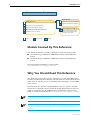
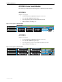
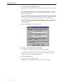
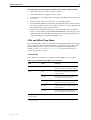
AT-8700XL Series Switch
Hardware Reference
AT-8724XL
AT-8748XL
AT-8700XL Series Hardware Reference
Document Number C613-03064-00 REV E.
© 2006 Allied Telesis Inc. All rights reserved. No part of this publication may be
reproduced without prior written permission from Allied Telesis Inc.
Allied Telesis Inc. reserves the right to change specifications and other information in
this document without prior written notice. The information provided herein is subject
to change without notice. In no event shall Allied Telesis Inc. be liable for any incidental,
special, indirect, or consequential damages whatsoever, including but not limited to lost
profits, arising out of or related to this manual or the information contained herein, even
if Allied Telesis Inc. has been advised of, known, or should have known, the possibility
of such damages.
All company names, logos, and product designs that are trademarks or registered
trademarks are the property of their respective owners.
Hardware Reference
3
Contents
Models Covered By This Reference .................................................................... 4
Why You Should Read This Reference ............................................................... 4
Where To Find More Information ...................................................................... 5
Hardware Description ....................................................................................... 5
Switch Overview ......................................................................................... 5
AT-8700XL Series Switch Models ................................................................ 7
AT-8724XL ................................................................................................. 7
AT-8748XL ................................................................................................. 7
Online Documentation ...................................................................................... 8
Accessing the CD-ROM and Online Documentation .................................... 8
AT-TFTP Server ................................................................................................... 8
Switch Start-up ............................................................................................... 10
To Log In .................................................................................................. 10
To access help files ................................................................................... 10
Start-up Procedures .................................................................................. 11
Switch Interfaces ............................................................................................ 13
RS-232 Terminal Port ................................................................................ 13
Switch RJ-45 Ports .................................................................................... 14
Redundant Power Supply ......................................................................... 16
Switch Cables and Loopback Plugs ................................................................. 17
Terminal and Modem Cables .................................................................... 17
Loopback Plugs for Testing Switch Interfaces ............................................ 19
Test Facility ..................................................................................................... 19
10/100 Ethernet LAN Port Tests ................................................................ 20
Troubleshooting .............................................................................................. 20
LEDs and What They Mean ....................................................................... 21
Some common problems and how to solve them ..................................... 24
Expansion Options .......................................................................................... 25
Uplink Modules ........................................................................................ 25
Port, Connector, and Cable Combinations ...................................................... 26
Using Windows Terminal and Windows Hyperterminal .................................... 26
Restricted Procedures ...................................................................................... 29
Diagnostics ............................................................................................... 29
Replacing Boot EPROMs ........................................................................... 30
Troubleshooting EPROM Installation ......................................................... 33
Contacting Us ................................................................................................. 33
C613-03064-00 REV E
4
AT-8700XL Series
Documentation Roadmap
Uplink Module
AT-8700XL Series
Uplink Module Quick Install Guide
AT-8700XL Series Safety and Statutory Information Booklet
Uplink Module Hardware Reference
AT-8700XL Series Quick Install Guide
AT-8700XL Series Software Reference
General Customer Support
AT-8700XL Series Hardware Reference
Visit www.alliedtelesyn.co.nz for
the latest documentation, FAQs,
and support information.
AT-8700XL Series User Guide
Printed
Acrobat PDF
Website
Models Covered By This Reference
This Hardware Reference includes information on the following models:
■
AT-8724XL 24-port 10BASE-T/100BASE-TX Advanced Fast Ethernet
Switch
■
AT-8748XL 48-port 10BASE-T/100BASE-TX Advanced Fast Ethernet
Switch
The latest Hardware Reference can be found at
www.alliedtelesis.com/support/software.
Why You Should Read This Reference
This Reference has been developed to familiarise you with AT-8700XL Series
switches and their hardware features. The information found in this Reference
will assist you with the process of installing and maintaining your AT-8700XL
Series switch.
The Reference also introduces Uplink Module expansion options. Detailed
information on Uplinks can be found in the Uplink Module Hardware Reference,
which is included on the AT-8700XL Series Documentation and Tools CDROM, or can be downloaded from www.alliedtelesis.com/support/software.
Keep this Reference (or its CD-ROM) in a safe place, you will need it if you purchase
switch expansion options in the future.
This Reference does not cover software configuration or software installation
procedures. For information on software, refer to the AT-8700XL Series Software
Reference.
C613-03064-00 REV E
Hardware Reference
5
Where To Find More Information
The Documentation and Tools CD-ROM bundled with each AT-8700XL Series
switch contains the complete Document Set for your switch and its expansion
options, as well as tools for managing the switch. This includes:
■
The AT-8700XL Series Safety Booklet, which provides safety and statutory
information.
■
The AT-8700XL Series Quick Install Guide, which outlines the procedure for
installing switch units; and this AT-8700XL Series Hardware Reference.
■
The AT-8700XL Series Software Reference, which provides detailed
information on configuring the switch and its software.
■
The Uplink Module Quick Install Guide, which outlines the procedure for
installing an Uplink Module; and the Uplink Module Hardware Reference,
which provides detailed information on Uplink Modules.
■
AT-TFTP Server for Windows, for downloading software releases.
■
Adobe Acrobat Reader, for viewing online documentation.
■
Microsoft Internet Explorer.
These documents can also be downloaded from www.alliedtelesis.com/
support/software.
Hardware Description
This section provides an overview of the hardware features for AT-8700XL
Series switches. Hardware descriptions for Uplink Modules can be found in the
Uplink Module Hardware Reference. These references can be found on the
CD-ROM bundled with your switch, or can be downloaded from
www.alliedtelesis.com/support/software.
Switch Overview
AT-8700XL Series switches deliver low-latency high-bandwidth wire-speed
Layer 2 and 3 switching to the desktop. RJ-45 copper ports ensure industrystandard compatibility, while two gigabit uplink module bays add expansion
and configuration flexibility.
Dimensions
•
Height = 66 mm (plus 5.5 mm if the rubber feet are used)
•
Width = 440 mm (excluding rack-mounting brackets)
•
Depth = 360 mm
•
Weight = Not more than 7 kg, depending on model (excluding power
cord)
Mounting System
•
C613-03064-00 REV E
1.5U rack mounting
6
AT-8700XL Series
Environmental Conditions
•
Operating temperature range: 0 to 40º C (32 to 104º F)
•
Storage temperature range: -25 to 70º C (-13 to 158º F)
•
Relative humidity range: 5 to 95% non-condensing
Regulatory Standards
•
EMC: CISPR22 class A, FCC class A, and VCCI class I
•
Immunity testing to EN50082 levels 2 (ESD), 3 (susceptibility), 4 (fast
transients), 5 (power surge), and 6 (RF immunity)
•
Safety: UL1950, CSA22.2, EN60950
LEDs
•
Ethernet port and System status LEDs
•
For a complete list of LEDs and their functions, see “Fault Indicators
and What They Mean” on page 24.
Power Supply Unit
AC models
•
Universal 110/240 VAC 50/60 Hz input
•
Redundant DC Power connection
DC models
•
48 VDC (39-60 VDC is acceptable)
•
Models other than the NEBS compliant AT-8724XL can operate with
either positive or negative earthing (grounding). The NEBS compliant
AT-8724XL should only be connected with positive earthing.
Switching Core
•
Advanced ASIC switch chip
•
Wire-speed L2 and L3 IP Switching
Processing Core
•
200 MHz RISC Processor
•
32 MBytes Synchronous DRAM
•
8 MBytes flash memory
•
128 KBytes Non-volatile Storage (battery backed SRAM)
Asynchronous Serial Port
•
Up to 115 kbps
•
Standard DB9 female RS-232 connector
•
Hardware-flow control
Uplink Module Bays
•
2 very high performance bays
•
Support for gigabit Ethernet uplink modules
C613-03064-00 REV E
Hardware Reference
7
AT-8700XL Series Switch Models
This section provides hardware descriptions for individual switch models.
AT-8724XL
(Figure 1 on page 7)
•
24-port 10BASE-T/100BASE-TX (RJ-45 connectors)
•
Two 10/100/1000BASE uplink bays
•
Auto-negotiating Advanced Fast Ethernet Switch
•
Enhanced 5615 switching core
Figure 1: Front panel of the AT-8724XL.
AT-8724XL
Advanced Fast Ethernet Switch
25
10BASE-T / 100BASE-TX
1X
3X
5X
7X
9X
11X
13X
PORT ACTIVITY
15X
17X
19X
21X
23X
L /A
100M LINK /
D/C
FULL DUP
1
3
5
ACTIVITY
7
9
11
13
RS-232
TERMINAL PORT
10M LINK /
ACTIVITY
HALF DUP/
COL
15
17
19
21
23
STATUS
ASYN0
FAULT
L /A
D/C
26
RPS
L /A
PWR
D/C
2
2X
4X
6X
8X
10X
12X
14X
16X
18X
20X
22X
4
6
8
10
12
14
16
18
20
22
24
24X
AT-8748XL
(Figure 2 on page 7)
•
48-port 10BASE-T/100BASE-TX (RJ-45 connectors)
•
Two 10/100/1000BASE uplink bays
•
Auto-negotiating Layer 3 Advanced Fast Ethernet Switch
•
Enhanced 5615 switching core
Figure 2: Front panel of the AT-8748XL.
C613-03064-00 REV E
RESET
8
AT-8700XL Series
Online Documentation
This section provides a step-by-step guide to accessing online documentation.
Adobe Acrobat Reader must be installed to view online documentation.
Accessing the CD-ROM and Online Documentation
Follow these steps to access the CD-ROM and online documentation:
1.
Insert the AT-8700XL Series Documentation and Tools CD-ROM in the CD-ROM
drive.
2.
If the CD browser screen does not appear.
Select "Run" from the Start Menu (Windows 95, 98, 2000 or NT 4.0).
Type d:\start.exe (where d: is the CD-ROM drive letter) and click OK.
3.
To view a document.
Click on the document title.
4.
To navigate around PDF documents.
Use the toolbar buttons, keyboard shortcuts, or commands from the
Document menu to page through the document.
Click on a bookmark, thumbnail or hypertext link to jump to a specific
section or topic.
Use the Search command to search for keywords or phrases.
For more information about using the Adobe Acrobat Reader, select
"Reader Guide" from the Help menu.
5.
To install any of the tools included on the CD-ROM.
Click on a link in the CD browser.
AT-TFTP Server
This section provides information on how to access and use AT-TFTP Server.
AT-TFTP Server can be used to transfer configuration files as well as to
download software patches and releases.
To use AT-TFTP Server, follow these steps:
1.
If AT-TFTP Server has not yet been installed.
Install it now from the AT-8700XL Series Documentation and Tools CDROM.
Choose AT-TFTP Server from the Start > Programs > Allied Telesis >
AT-TFTP Server menu.
C613-03064-00 REV E
Hardware Reference
9
2.
To set preferences for the AT-TFTP Server.
Select "Options" from the File menu to display the "Set Preferences" dialog
box.
The "Default file transfer directory" field specifies the directory that ATTFTP Server will read from or write to for file requests that do not include a
directory specification.
To prevent unauthorised access to private directories, enter a path name in
the "Restrict to directory" field. AT-TFTP Server will use only the specified
directory, even if file requests contain references to other directories.
Select "Read only" to prevent files being written to the PC. To use the PC to
archive scripts created using the switch’s CREATE CONFIG command,
select "Read Write".
Make any required changes and click "OK".
3.
To load a file from AT-TFTP Server to the Switch.
On a terminal connected to the switch, type the command:
LOAD METHOD=TFTP FILE=filename SERVER=ipadd DEST=FLASH
where filename is the name of the file to download and ipadd is the IP
address of the PC running AT-TFTP Server.
4.
To save a TFTP Server log.
Select "Save As" from the File menu.
TFTP requests are logged to the AT-TFTP Server main window.
C613-03064-00 REV E
10
AT-8700XL Series
Switch Start-up
This section outlines the log in and start-up procedures for your switch.
Although the switch will perform basic switching operations without being
configured, you will need to go through these log in and start-up procedures if
you wish to configure the switch and access its full switching capabilities.
To Log In
Using the supplied RS-232 DB9 straight-through cable, connect your
terminal or PC to the RS-232 Terminal Port on the switch’s front panel.
Set the communication parameters on your terminal or terminal emulation
program to:
•
Baud rate: 9600
•
Data bits: 8
•
Parity: None
•
Stop bits: 1
•
Flow control: Hardware
See “Using Windows Terminal and Windows Hyperterminal” on page 37
for more information on configuring emulation software.
After the switch has booted, the log in prompt appears. If the log in prompt
doesn’t appear, press [Enter] two or three times.
When the switch boots for the first time it automatically creates an account
with manager privileges. The account has the log in name “manager” and
the password is “friend”.
At the log in prompt, enter the log in name and password.
Log in: manager
Password: friend
The switch’s command prompt appears and you can now configure the
switch using the command line interface.
Change the password as soon as possible. Leaving the manager account with
the default password is a serious security risk. Make sure that you remember
the new password as there is no way to retrieve it if it is lost.
Use the following command to change the account password:
set password
See the AT-8700XL Series Software Reference for more information on
configuring the switch.
To access help files
Before help is used for the first time, the help files must be defined.
To define the files, enter:
set help=help-filename
where help-filename is the name of a help file stored in flash.
C613-03064-00 REV E
Hardware Reference
11
To see a list of files stored in flash, enter:
show file
Help files have an HLP extension.
To display a list of help topics, enter:
help
To display help on a specific topic, enter:
help topic
Alternatively, type a question mark (?) at the end of a partially completed
command to see a list of valid options.
Start-up Procedures
When the switch starts up following either a power cycle or an operatorinitiated reboot (using the Reset button or RESTART command), a series of
start-up messages is sent to the RS-232 Terminal Port (Figure 3 on page 11).
Figure 3: Switch start-up messages.
INFO:
INFO:
PASS:
INFO:
PASS:
INFO:
INFO:
Force
INFO:
INFO:
INFO:
Self tests beginning.
RAM test beginning.
RAM test, 32768k bytes found.
BBR tests beginning.
BBR test, 128k bytes found.
Self tests complete
Downloading switch software.
EPROM download (Y) ?
Initial download succeeded
Executing configuration script <boot.cfg>
Switch startup complete
Manager >
After the self tests are complete, the manager is given the option of forcing a
mandatory boot from the EPROM release. The message:
Force EPROM download (Y)?
is displayed on the terminal connected to the RS-232 Terminal Port and the
switch pauses. If a key is not pressed within a few seconds, the start-up process
will continue and all steps in the sequence will be executed. Pressing selected
keys on the terminal immediately after the “Force EPROM download” message
is displayed will change the switch start-up process (Table 1 on page 11).
Table 1: Switch start-up sequence keystrokes.
Pressing key...
Forces the switch to...
[Y]
Load the EPROM release, with no patch.
[S]
Start with the default configuration. Any boot script is ignored.
[Ctrl/D]
Enter diagnostics mode.
During the start-up process the switch will generate four different types of
messages. All messages are preceded by one of the words INFO, PASS, FAIL,
or ERROR. The significance of these words is shown in Table 2 on page 12.
C613-03064-00 REV E
12
AT-8700XL Series
Table 2: Switch start-up message classes.
Message
Meaning
INFO
An action will be taken by the system.
PASS
A test has been completed successfully.
ERROR
An error message that a test has failed, but the system will continue to
operate.
FAIL
An error message that a fatal error condition has caused the system to
halt in an unrecoverable fashion.
The possible messages and their meanings are:
INFO: Self tests beginning.
The code loader tests are about to begin.
INFO: RAM test beginning.
The RAM tests are about to begin.
PASS: RAM test, 32768k bytes found.
The RAM test passed, and the indicated amount of memory was found
and will be used in the switch.
ERROR: RAM test 5. Error address = 00345678.
A RAM test failed, at the given address. In the example, it was the fifth
test run. The RAM test repeats until it passes, so a number of messages
like this may appear. This fault means that the memory system is faulty.
If the fault continues, contact your Authorised Allied Telesis distributor
or reseller immediately.
INFO: BBR tests beginning.
The BBR battery tests are about to begin.
PASS: BBR test. Battery OK.
The BBR battery tests passed.
ERROR: BBR Battery low.
The BBR battery test failed, indicating that the battery is running low.
The BBR battery will need to be replaced. Contact your Authorised
Allied Telesis distributor or reseller.
PASS: BBR test, 256k bytes found.
The BBR size/location test passed, with the indicated amount of BBR
found.
FAIL: BBR test. Error address = 12345678.
The BBR size/location test failed at the given location. The test at this
location failed, indicating the end of memory, but a valid location was
discovered in the 255 long words following this location. The BBR
system will need to be replaced. Contact your Authorised Allied Telesis
distributor or reseller.
FAIL: BBR test, only 16k bytes found.
The BBR size/location test completed, but only the displayed amount
of memory was found. This amount is less than the minimum required
to run the switch software.
INFO: Self tests complete.
The start-up tests have finished.
INFO: Downloading switch software.
The process of downloading the switch software and vector table from
ROM is about to begin.
C613-03064-00 REV E
Hardware Reference
13
ERROR: Code load retried.
FAIL: Code load failed.
The load of the code from ROM to RAM failed. The load is retried a
number of times. Each time a failure occurs, the ERROR message is
displayed. If the maximum number of attempts is reached, the FAIL
message is displayed.
INFO: Initial download succeeded.
The start-up tests and download are complete, and the switch software
is about to be started. If the default install is a compressed release, the
release will now be decompressed. This may take a few seconds.
INFO: Downloading compressed release. This may take up to 1
minute...
INFO: Loading software into memory. This may take up to 1
minute...
The main switch software is about to be loaded into RAM. If the release
is a compressed release, the release will be decompressed.
INFO: Executing configuration script <script-name>
The configuration commands stored in <script-name> are being
executed. If an error is found in the script, one or more ERROR
messages will be displayed.
INFO: Switch startup complete.
The start-up process is complete and the switch will now perform basic
switching operations. Further configuration will be necessary if you wish to
access the switch’s full switching capabilities. See the AT-8700XL Series Software
Reference for detailed information on configuring the switch.
Switch Interfaces
This section provides pin assignments for the switch’s RS-232 Terminal Port
and RJ-45 ports, and the Redundant Power Supply (RPS) connector.
RS-232 Terminal Port
The RS-232 Terminal Port is used to connect the switch to a management
device. For management purposes the switch’s software can be accessed from a
terminal, a PC running terminal emulation software, or from a remote location
via a modem connection. You can also use the RS-232 Terminal Port to establish
a network connection from a remote site using SLIP and a modem.
The switch’s RS-232 Terminal Port has a DCE female socket. This allows the use
of a straight-through cable when connecting the switch to a terminal or PC.
Output from the SHOW ASYN command will, however, still have a DTE
perspective. The internal DTE pin roles are listed in Table 3 on page 14.
See Terminal and Modem Cables on page 20 for more information on
connection options for the RS-232 Terminal Port.
C613-03064-00 REV E
14
AT-8700XL Series
Figure 4: RS-232 Terminal Port Pin Numbers.
Pin 5
Pin 9
Pin 1
Pin 6
DB9 Female Pin View
Table 3: Internal DTE pin roles.
Pin
Role
2
TXD
3
RXD
4
CD
5
GND
6
DTR
7
CTS
8
RTS
Switch RJ-45 Ports
Caution. Do not plug a phone jack into any RJ-45 port. Doing so could damage
the switch. Use only twisted pair cables with RJ-45 connectors.
For 10BASE-T/100BASE-TX connections, a twisted pair cable must be used.
Each pair is identified by two different colours. For example, one wire might be
red, and the other red with a white stripe. An RJ-45 connector must be fitted to
both ends of the cable. Figure 5 on page 14 illustrates the pin layout for RJ-45
connectors.
Figure 5: RJ-45 Pin layout.
8
1
8
1
RJPIN
With 10BASE-T/100BASE-TX cables, pins 1 and 2 are used for transmitting
data, while pins 3 and 6 are used for receiving data. Table 4 on page 15 lists the
RJ-45 Pin assignments.
C613-03064-00 REV E
Hardware Reference
15
Table 4: RJ-45 Pin assignments.
Pin Number
Assignment1
1
TX+
2
TX-
3
RX+
6
RX-
1. The “+” and “-” signs represent the polarity of the wires that make up each wire pair.
If a twisted pair cable is to join two ports and only one of the ports has an
internal crossover, the two pairs must be straight through, as listed in Table 5
on page 15.
Table 5: RJ-45 Pin assignments, straight through cable.
End 1
End 2
1 (TX+)
1 (TX+)
2 (TX-)
2 (TX-)
3 (RX+)
3 (RX+)
6 (RX-)
6 (RX-)
If a twisted pair cable is used to join two ports and either both ports are
labelled with an “X” or neither port is labelled with an “X”, a crossover must be
included in the wiring. Table 6 on page 15 lists the RJ-45 crossover wiring pin
assignments.
Table 6: RJ-45 Pin assignments, crossover cable.
C613-03064-00 REV E
End 1
End 2
1 (TX+)
3 (TX+)
2 (TX-)
6 (TX-)
3 (RX+)
1 (RX+)
6 (RX-)
2 (RX-)
16
AT-8700XL Series
Redundant Power Supply
AC models of AT-8700XL Series switches have a Redundant Power Supply
(RPS) connector on their rear panel. Table 7 on page 16 lists the connector’s pin
numbers and pin functions.
Table 7: RPS Connector Pin Numbers and Functions.
Pin Number
Function
1
+12 VDC
2
Remote Sense (RS) +5 VDC
3
Remote Sense (RS) Ground
4
Remote Sense (RS) +3.3 VDC
5
Redundant Power Supply (RPS) Present
6
Ground (+3.3 VDC Return)
7
Ground (+5 VDC Return)
8
+5 VDC
9
Ground (+12 VDC Return)
10
+3.3 VDC
11
Ground (+3.3 VDC Return)
12
+3.3 VDC
13
Ground (+3.3 VDC Return)
14
+3.3 VDC
15
+5 VDC
16
Ground (+5 VDC Return)
Table 8 on page 16 illustrates the connector’s pin layout.
Table 8: RPS Connector’s Pin Layout.
16
15
14
13
12
11
10
9
8
7
6
5
4
3
2
1
Pin 16 is at the connector’s top left, while pin 1 is at its lower right.
C613-03064-00 REV E
Hardware Reference
17
Switch Cables and Loopback Plugs
This section describes how to make cables for connecting the switch’s
interfaces to networks, terminals, and printers. How to make loopback plugs
for testing switch interfaces is also described.
Terminal and Modem Cables
Figure 6 on page 17 shows how to wire cables to connect a standard VT100
compatible terminal, or a modem, to the switch’s
RS-232 Terminal Port.
Figure 6: Pin wiring diagram for a standard DB9 male to female terminal cable.
DB9 Male
(to switch/DCE)
Not connected
→ (TXD)
← (RXD)
← (CD)
(GND)
→ (DTR)
← (CTS)
→ (RTS)
← (RING)
Pin 1
DB9 Female
(to PC/terminal/DTE)
1
2
3
4
5
6
7
8
9
1
2
3
4
5
6
7
8
9
Pin 5
Pin 5
(DCD)
(RXD)
(TXD)
(DTR)
(GND)
(DSR)
(RTS)
(CTS)
(RING)
Pin 1
Cable
Pin 6
Pin 9
DB9 Male Pin View
Notes:
(1)
(2)
Pin 9
Pin 6
DB9 Female Pin View
→ Output from switch; ← Input to switch.
Cable version 1.0.
DB9MDB9Fsw
C613-03064-00 REV E
18
AT-8700XL Series
Figure 7: Pin wiring diagram for a DCE RS-232 Terminal Port (DB9 female
connector) male to male modem cable.
DB9 Male
(to switch/DCE)
Not connected
→ (TXD)
← (RXD)
← (CD)
(GND)
→ (DTR)
← (CTS)
→ (RTS)
(RING)
Pin 1
DB9 Male
(to modem/DCE)
1
2
3
4
5
6
7
8
9
3 (TXD)
2 (RXD)
1 (DCD)
5 (GND)
4 (DTR)
8 (CTS)
7 (RTS)
9
6 Not connected
Pin 5
Pin 5
Pin 1
Cable
Pin 6
Pin 9
Pin 9
DB9 Male Pin View
Notes:
(1)
(2)
Pin 6
DB9 Male Pin View
→ Output from switch; ← Input to switch
Cable version 1.0.
DB9MDB9Fsw
The switch’s RS-232 Terminal Port has a DCE female socket. This allows the use
of a straight-through cable when connecting the switch to a terminal or PC.
Output from the SHOW ASYN command will, however, still have a DTE
perspective. The internal DTE pin roles are listed in Table 9 on page 18.
Table 9: Internal DTE pin roles.
Pin
Role
2
TXD
3
RXD
4
CD
5
GND
6
DTR
7
CTS
8
RTS
C613-03064-00 REV E
Hardware Reference
19
Loopback Plugs for Testing Switch Interfaces
Loopback plugs are used in conjunction with the Test Facility software to test
the physical interfaces on the switch (see the “Test Facility” section beginning
on page 22 of this Reference, and the Test Facility chapter of the AT-8700XL
Series Software Reference). The purpose of a loopback plug is to connect the
output pins on the interface to the input pins so that any data transmitted over
the interface is looped back and received at the same interface.
Gigabit copper interfaces (as found on the AT-A39/T uplink module) cannot be looped
back. Loopback plugs can only be used in conjunction with 10/100 Ethernet interfaces.
On interfaces with control signals, these are also looped back. The data
received on the interface is compared with the data transmitted to determine
whether or not the interface is functioning correctly. In order to produce a
comprehensive test report for the interface being tested, most tests performed
by the Test Facility require a loopback plug to be inserted.
Figure 8: Ethernet twisted pair (TP) loopback plug.
Twisted Pair (TP) Loopback Plug (RJ45 connector)
8 7 6 5 4 3 2 1
TX+
TXRX+
RX-
1
2
3
4
5
6
7
8
Not
connected
Not
connected
•Not
Switch end view
of plug
RTPLOOPsw
Test Facility
This section introduces the Test Facility. The Test Facility is built into all
AT-8700XL Series software. For detailed information on operating the Test
Facility, see the Test Facility chapter of the AT-8700XL Series Software
Reference.
The Test Facility is designed to test the switch’s physical interfaces. Testing
should not be performed while the switch is operational as the presence of a
loopback plug may cause feedback of network traffic. Also, any interfaces
being tested are dedicated to the Test Facility. The Test Facility can be thought
of as a specialised interface module like PPP or Frame Relay.
Test results are displayed with the command:
SHOW TEST
which produces a display like that shown in Figure 9 on page 20.
C613-03064-00 REV E
20
AT-8700XL Series
Figure 9: Example output from the SHOW TEST command.
Board
ID Bay Board Name
Rev
Serial number
---------------------------------------------------------------------------Base
108
8724 AT-8724XL
M1-1 6845425
Uplink
88
1 AT-A35SX/SC-00
P1-0 14269019
Duration
Details
Interface State
Result
Type (minutes) Data( %OK ) Control
---------------------------------------------------------------------------port1
no test
port2
no test
port3
no test
port4
no test
port5
no test
port6
no test
port7
no test
port8
no test
port9
no test
port10 no test
port11 no test
port12 no test
port13 no test
port14 no test
port15 no test
port16 no test
port17 no test
port18 no test
port19 no test
port20 no test
port21 no test
port22 no test
port23 no test
port24 no test
port26 no test
asyn0
no test
----------------------------------------------------------------------------
10/100 Ethernet LAN Port Tests
A loopback plug is required to run the first part of the Ethernet LAN test. See
“Loopback Plugs for Testing Switch Interfaces” on page 22 for details of how to
make a loopback plug. To start an Ethernet interface test, use the command:
ENABLE TEST INT=PORTn
where n is the Ethernet interface number. The test will run for 4 minutes. Use
the SHOW TEST command to observe the test progress.
Troubleshooting
This section provides information on how to detect and resolve problems with
AT-8700XL Series switches and their expansion options.
Other sources of useful troubleshooting information are:
■
www.alliedtelesis.com/support/software.
■
The AT-8700XL Series Software Reference.
C613-03064-00 REV E
Hardware Reference
21
Performing the following tasks will eliminate the most common faults.
1.
Make sure the power cord is securely connected.
2.
Check that the power supply voltage is stable.
3.
Check that the correct data cables are being used and that their connections
are secure.
4.
Make sure that other network devices are working properly.
5.
Use the SHOW INSTALL command to check that the latest software release
is loaded. See the AT-8700XL Series Software Reference for more information
about obtaining the latest software release.
6.
If the switch is malfunctioning, reboot it by pressing the recessed Reset
button or entering the command RESTART REBOOT. Alternatively, power
OFF and ON the switch by disconnecting and reconnecting the main power
supply (including, if connected, the RPS power).
LEDs and What They Mean
The following tables outline how the Switch and Uplink Modules report faults
and operational activities. Uplink Modules are expansion options and can be
purchased separately. Contact an Authorised Allied Telesis distributer or
reseller, or visit www.alliedtelesis.com/support for more information on
purchasing expansion options.
Switch LEDs
These LEDs are on the front or rear panels of AT-8700XL Series switches.
Table 10: System LEDs (All AT-8700XL Series switches).
LED
State
Function
Power
Green
The switch is receiving power and the
voltage is within the acceptable range
Fault
Red
The switch or management software is
malfunctioning
1 flash
A switch fan has failed. (The LEDs will
not indicate an RPS fan failure.)
3 flashes
If an RPS is connected, the switch’s
PSU (Power Supply Unit) has failed
4 flashes
If RPS monitoring is enabled, the RPS
PSU has failed
5 flashes
If RPS monitoring is enabled, an RPS is
not connected or is not operational
Green
An RPS is connected to the switch
RPS 1 (Redundant
Power Supply)
1. DC models of the AT-8700XL Series switches do not have an RPS connector and the RPS LED
will not function
C613-03064-00 REV E
22
AT-8700XL Series
Table 11: Switch Port LEDs (AT-8724XL and AT-8748XL).
LED
State
Function
L/A (Link/Activity)
Green
A 100 Mbps link is open
Flashing Green
100 Mbps activity is occurring
Amber
A 10 Mbps link is open
Flashing Amber
10 Mbps activity is occurring
Green
The port is operating at full-duplex
Amber
The port is operating at half-duplex
Flashing Amber
Collisions are occurring on the line
D/C
(Duplex/Collision)
Uplink Module LEDs
The following tables may be helpful when diagnosing possible operational
faults. These LEDs are located on the face-plate of the respective Uplink
Module model.
Table 12: Uplink Module LEDs (AT-A35-SX/SC and AT-A35-LX/SC).
LED
State
Function
Link
Green
The port is receiving light
Off
No link is present
Flashing Amber
Frames are being transmitted or received
through the port
Off
No activity is occurring
Activity
Table13: Uplink Module LEDs (AT-A39-T/RJ-45).
LED
State
Function
Full Dup/Half
Dup/Col
Green
The port is operating at full-duplex
Amber
The port is operating at half-duplex
Flashing amber
Collisions are occurring
Off
No link is present
Green
A 1000 Mbps link is open
Flashing green
1000 Mbps activity is occurring
Amber1
A 10/100 Mbps link is open
Flashing Amber1
10/100 Mbps activity is occurring
Off
No link is present
Activity
1. Early versions of the AT-A39/T operate at 1000 Mbps only.
C613-03064-00 REV E
Hardware Reference
23
Table: 14 AT-A40/SC, AT-A40/MT, AT-A41/SC and AT-A41/MT LEDs.
LED
State
Function
Activity/Link/Fault
Green
A link is open and the port is enabled
Flashing green
100 Mbps activity is occurring
Flashing amber
(and lower LED is Off)
The link has failed at the remote end
Off
No link is present
Green
The port is operating at full-duplex
Amber
The port is operating at half-duplex
Flashing amber
Collisions are occurring
Off
No link is present
Alternate flashing of
upper and lower LED,
amber
The switch does not support this model of
uplink module
Full Dup/Half
Dup/Col
Both LEDs
Table: 15 AT-A42/GBIC LEDs .
LED
State
Function
L/A
Green
A 1000 Mbps link is open
Flashing green
1000 Mbps activity is occurring
Flashing amber
(and GBIC LED is Off)
A TX fault has occurred
Off
No link is present
Green
The switch has recognised the GBIC,
the GBIC is a valid model
Green
(and L/A LED is flashing
GREEN)
The port is operating at full-duplex
Amber
(and L/A LED is OFF)
The switch has not recognised the
GBIC, the GBIC is not a valid model
Amber
(and L/A LED is flashing
GREEN)
The port is operating at half-duplex
Flashing amber
(and L/A LED is flashing
GREEN)
Collisions are occurring
Off
No GBIC is installed, or a TX fault has
occurred
Slow alternate flashing of
L/A and GBIC LED, amber
The switch has not recognised the
GBIC, or the GBIC is not a valid model
Link/Activity
GBIC
Both LEDs
C613-03064-00 REV E
24
AT-8700XL Series
Some common problems and how to solve them
Link/Activity LED on any port is off
This can indicate:
■
A loose data cable.
■
The device at the other end of the connection is not working properly or is
turned off.
■
The data cable is not wired correctly.
■
The network administrator has manually disabled the port through the
software.
■
The port’s selected transmission mode does not match that of the attached
device.
Perform the following steps in sequence:
1.
Make sure the data cable connections are secure.
2.
Make sure the device at the other end of the connection is switched on and
working properly.
3.
Check that the data cable is wired correctly.
4.
If you can, log in and check the port status. See “To Log In” on page 12 for
more information on how to log in.
5.
If the port is Enabled, make sure the transmission speed matches that of the
connected device (auto-negotiating, full or half-duplex).
If the port is disabled, someone has used the software to manually disable it. You should
find out why the port was disabled before enabling it.
Power LED is off
This can indicate:
■
A loose power cord.
■
A power supply failure.
Perform the following steps in sequence:
1.
Check that the power cord connections are secure.
2.
Check that all switches and circuit protection devices are in the ON position.
3.
Ensure that the supply voltage is within the operational range (110/240
VAC 50/60 Hz for AC models, 39-60 VDC for DC models).
Fault LED is on
This can indicate:
■
There is a problem with the switch or RPS PSU.
■
The switch or management software is malfunctioning.
■
A hardware fault is preventing switch start-up.
C613-03064-00 REV E
Hardware Reference
25
Perform the following steps in sequence:
1.
Check Table 10 on page 21 for descriptions and explanations of LED
flashing sequences.
2.
Reset the switch by pressing the recessed RESET button on the front panel.
3.
If you were attempting to download software or manage the switch via the
RS-232 terminal Port, check that connections between the Terminal Port and
local terminal or PC are secure.
If you cannot access the switch’s software because of a faulty RS-232
Terminal Port connection, you can still manage the switch via Telnet or
SNMP until the problem is fixed.
4.
Unplug the switch and then plug it in again. If present, you will also have
to disconnect and reconnect the RPS unit.
5.
Download the latest software release. See the AT-8700XL Series Software
Reference for more information on how to obtain the latest software release.
Expansion Options
This section provides an overview of the expansion options for AT-8700XL
Series switches. The following expansion options were available when this
Reference was written. See your Authorised Allied Telesis distributer or
reseller, or visit www.alliedtelesis.com/support/software to see if any new
options are available.
Uplink Modules
Uplink Modules increase switching capacity by providing a maximum of two
extra ports and by allowing switches to be linked together in stacks. For the
AT-8700XL Series, Uplink Modules with gigabit capacity are available.
Uplink Modules in the following list are the only modules that should be
installed into AT-8700XL Series switches. Check with your Authorised Allied
Telesis distributor or reseller, or visit www.alliedtelesis.com to see if any new
Uplink Module models are available.
Uplink Modules currently available include:
■
AT-A35-SX/SC 1-port 1000BASE-SX (SC connector)
■
AT-A35-LX/SC 1-port 1000BASE-LX (SC connector)
■
AT-A39-T/RJ-45 1-port 1000BASE-T (RJ-45 copper connector)
■
AT-A40/SC 1-port 100BASE-FX Multimode Fibre (SC connector)
■
AT-A40/MT 1-port 100BASE-FX Multimode Fibre (MT-RJ connector)
■
AT-A41/SC 1-port 100BASE-FX Singlemode Fibre (SC connector)
■
AT-A41/MT 1-port 100BASE-FX Singlemode Fibre (MT-RJ connector)
■
AT-A42/GBIC 1-port 1000BASE-X (GBIC slot)
For more information on Uplink Modules, contact your Authorised Allied Telesis
distributor or reseller, or see the Uplink Module Hardware Reference. This and other
documentation can be found on the AT-8700XL Series Documentation and Tools
CD-ROM bundled with your switch, or at www.alliedtelesis.com/support/software.
C613-03064-00 REV E
26
AT-8700XL Series
Port, Connector, and Cable Combinations
This section provides cabling guidelines for each switch model.
Table 16: Cable guidelines.
Model
Port Type(s)
Connector Type(s)
Cable Type1
Maximum Cable
Length
AT-8724XL
10BASE-T/
100BASE-TX
RJ-45
10BASE-T Category 3 or
better
100m (328ft)
100BASE-TX Category 5
or better
100m (328ft)
AT-8748XL
1. Refer to the IEEE 802.3 standards for further cable information
C613-03064-00 REV E
Hardware Reference
27
Using Windows Terminal and Windows
Hyperterminal
You can use a PC running terminal emulation software as the manager console,
instead of a terminal. There are many terminal emulation applications
available for PCs, but the most readily available are the Terminal and
HyperTerminal applications included in Microsoft Windows 98, 2000, and
XP Professional. In standard Windows installations, HyperTerminal is
available from the Communications submenu.
The key to successful use of terminal emulation software with the switch is to
configure the software and switch with matching communications parameters.
The following procedure can be applied to most terminal emulation programs.
Dialog boxes in the procedure are from Windows 2000 and XP Professional.
To configure Windows HyperTerminal for 2000 and XP Professional
1.
2.
C613-03064-00 REV E
Start the program in Windows by doing one of the following:
•
Select Programs > Accessories > Communications > HyperTerminal.
•
Double-click the Hypertrm.exe icon.
In the Connection Description dialog box:
•
Enter a name for the connection, such as Admin.
•
Select an icon from the scrollable list and click the OK button.
28
AT-8700XL Series
3.
In the “Connect using” field on the Connect To dialog box, select the COM
port on the PC used to connect to the switch. and click the OK button.
4.
In the COMn Properties dialog box, set port parameters as follows, and click
the OK button.
C613-03064-00 REV E
Hardware Reference
29
5.
From the main HyperTerminal window, select Properties from the File
menu. Click the Settings tab, and set the Properties dialog box as follows.
6.
Click ASCII Setup to display the ASCII Setup dialog box, and ensure the
following options are not selected:
•
Echo typed characters locally
•
Append line feeds to incoming line ends
Set other parameters as necessary and click the OK buttons on both dialog
boxes to close them.
C613-03064-00 REV E
30
AT-8700XL Series
7.
Save the current session by selecting Save from the File menu on the main
HyperTerminal window. This creates a connection icon with the name you
assigned in the HyperTerminal group.
To use the configuration, double-click the connection icon. When the
HyperTerminal window appears, press the Enter key several times; the
switch’s login prompt is then displayed.
Restricted Procedures
This section contains procedures that should only be performed by authorised
service personnel. Unauthorised use of procedures in this section may cause
danger of injury from electric shock, damage to the switch, and invalidation of
the product warranty.
If you would like to know more about the procedures outlined in this section,
please contact your authorised Allied Telesis distributor or reseller.
Diagnostics
The switch software includes a set of diagnostic programs. These programs
perform basic level checks of all system components. They do not run in
conjunction with the normal operating code, and require that the system be
totally dedicated to their use. A detailed knowledge of the way the switch
hardware functions is necessary if diagnostics is to be used effectively.
The switch will not perform switching operations if diagnostics are running.
This section is not intended as a guide to the diagnostics software. Diagnostics
are designed to be run by service personnel only. For more information, contact
your Authorised Allied Telesis distributor or reseller.
To enable diagnostics mode:
1.
Connect a terminal to the RS-232 Terminal Port.
Using an RS-232 DB9 straight-through cable, connect a terminal to the
RS-232 Terminal Port on the switch.
Set the terminal communication parameters to the following:
2.
•
Baud rate: 9600
•
Data bits: 8
•
Parity: None
•
Stop bits: 1
•
Flow control: Hardware
Restart the switch.
Restart the switch, either by using a pen or pencil to operate the recessed
reset button on the front panel, or by using the terminal to log in and enter
the command:
RESTART REBOOT
See “To Log In” on page 12 for more information on how to log in.
C613-03064-00 REV E
Hardware Reference
31
3.
Enable diagnostics mode during start-up.
During the switch start-up process, at the prompt:
Force EPROM download (Y)?
press [Ctrl/D] on the terminal to enter diagnostics mode. A banner page will
be displayed on the terminal (Figure 10 on page 31). This can be used to
check that the terminal is correctly connected.
Figure 10: AT-8700XL Series diagnostics banner page.
* * * Diagnostic Mode * * *
version 25-Jul-02
Main Menu:
0. Restart
1. Full RAM test
2. ROM checksum test
3. Full FLASH test
4. Totally Erase FLASH
5. Battery backed RAM test
Enter selection ==>
To run a diagnostic program, enter the corresponding letter or number (or key).
There are several sub-menus to cover all the available options. Table 16 on
page 26 lists the control keys for diagnostic operations.
Table 17: Basic commands for running the diagnostics.
Key
Function
Q
Quits any running tests and displays the banner page.
S
Prints a summary of test results so far.
A reasonable understanding of the system’s structure is needed to operate
diagnostics and interpret the results.
To restore the switch to normal operation, use a pen or pencil to operate the
recessed reset button on the front panel, or press “0” (zero) to restart.
Replacing Boot EPROMs
AT-8700XL Series switches have two 512 kByte boot EPROMs. The boot
EPROMs contain bootstrap code, which loads the main code from a software
release file in FLASH memory. In rare circumstances the boot EPROM(s) may
need to be changed.
Boot EPROMs should not need to be replaced, except in rare circumstances.
Contact your Authorised Allied Telesis distributor or reseller before replacing
any boot EPROMs.
C613-03064-00 REV E
32
AT-8700XL Series
To change the boot EPROMs:
1.
Check that you have the correct tools and equipment available.
You will need a medium-sized posidrive screwdriver and an EPROM
extraction tool (or a small flat-bladed screwdriver). In addition, adequate
antistatic precautions must be used.
EPROMs, like most electronic equipment, are highly sensitive to electrostatic
damage. This can be particularly acute in the dry atmosphere normally
associated with computer rooms and typical offices. Before commencing work,
ensure that you have used an approved antistatic wrist strap to discharge any
buildup of static electricity. Wear the strap at all times during the following
procedure.
2.
Avoid injury by working in a safe environment.
The workspace should be free of hazards, and there should be sufficient
room to lay out the switch, the EPROM, and the tools.
3.
Disconnect the mains power cord.
4.
If fitted, disconnect the redundant power supply.
Do not take risks with mains or backup electricity. Do not attempt to remove
the lid of the switch unless all power cords have been disconnected from the
switch.
5.
Remove the switch’s lid.
Using a posidrive screwdriver, remove the 12 screws that secure the
switch’s lid. There are 5 screws located in countersunk holes on each side
of the lid, and 2 screws at the rear. The switch may need to be removed
from any rack mounting system before its lid can be removed.
6.
Remove the existing boot EPROMs.
The boot EPROM(s) should now be visible.
Figure 11 on page 33 shows the location of boot EPROMs on the CPU
board.
Remove the boot EPROMs using the extraction tool. Alternatively, a small
flat-bladed screwdriver can be used. If using a screwdriver, gently lever
each end of a particular boot EPROM a few millimetres at a time until it
comes free.
C613-03064-00 REV E
Hardware Reference
33
Figure 11: EPROM locations.
Boot EPROMs
Fan
8700eprom
7.
Insert the new boot EPROMs.
Insert the new boot EPROMs one at a time, using as a reference the location
number printed on the CPU board (e.g., “0” and “1”) and Figure 11 on
page 33. Check that the boot EPROMs are firmly seated.
Install the boot EPROMs the correct way up! Failure to do so will almost certainly
destroy them. The ‘top’ end of the EPROM has a notch. This should be positioned so that
the notched end of the EPROM is orientated as shown in Figure 11 on page 33.
8.
Replace the switch’s lid and power cord.
Replace the lid and secure it with the 12 posidrive screws. Connect the
power cord and (if disconnected in step 4) the RPS.
9.
Check that the switch is operating correctly.
Check that the switch boots up correctly. Connect the switch’s RS-232
Terminal Port to a terminal (see page 20 for information on connection
cables) and check the start-up messages. See “Switch Start-up” on page 12
for a list of start-up messages. Verify that the new software release is
installed by typing the command:
SHOW INSTALL
which will produce a display like that shown in Figure 12 on page 34. The
boot EPROM software release number is shown in the “Default” field.
Check that it is correct.
C613-03064-00 REV E
34
AT-8700XL Series
Figure 12: Example output from the SHOW INSTALL command.
Install
Release
Patch
-----------------------------------------------------------Temporary
Preferred
flash:load\86s-210.rez
Default
EPROM (86s-2.1.0)
-----------------------------------------------------------Current install
-----------------------------------------------------------Preferred
flash:load\86s-210.rez
-----------------------------------------------------------Install history
-----------------------------------------------------------No Temporary install selected
Preferred install selected
Preferred release successfully installed
------------------------------------------------------------
Troubleshooting EPROM Installation
If the switch fails to reboot or functions incorrectly, then the most likely cause is
that there is a problem with the way the boot EPROMs were installed. Repeat
the installation procedure, checking:
•
That the boot EPROMs are in the correct locations and oriented
correctly (using the relevant location diagram as a guide).
•
For bent pins. These should be carefully straightened.
If the switch still fails to reboot, replace the new boot EPROMs with the
original set and contact your Authorised Allied Telesis distributor or reseller.
Contacting Us
With locations covering all of the established markets in North America, Latin
America, Europe, Asia, and the Pacific, Allied Telesis provides localized sales
and technical support worldwide. To find our representative nearest you, visit
Allied Telesis on the web at: www.alliedtelesis.com/.
C613-03064-00 REV E